


Introduction
Mono-Block Model: |
KX2500.1 |
Attention:
Please record your purchase information in the area provided below. We recommend attaching the original sales receipt or a copy of it to this manual for future reference.
If you require service on this amplifier during the warranty period, you will need to provide this information and a copy of the receipt to Kicker to validate your warranty.
ALWAYS KEEP YOUR RECEIPT!
KX2500.1
Amplifier
Owner’s Manual
Congratulations!
You have just purchased the latest in amplifier technology to carry the famous KICKER name.
Your KICKER KX2500.1 amplifier is designed and built to give you years of powerful and trouble-free performance in SPL contests and on the street.
Please read this installation manual, it contains valuable information to help you get the most out of your new KX2500.1 amplifier.
This is your “fuel for Livin’ Loud ™”!
Authorized Kicker Dealer: |
_____________________________________________ |
Purchase Date: |
_____________________________________________ |
Amplifier Model Number: |
KX2500.1 |
Amplifier Serial Number: |
_____________________________________________ |
2 |
KX2500.1 Amplifier |

Features
Class D Mono Amplifier Delivers massive power into a single channel with greater efficiency than conventional class A/B amplification.
Low Impedance Operation Designed for stable operation and maximum power output into a 2 ohm load.
SORT Protection Circuitry (Short circuit, Over-voltage, Reverse polarity, Thermal) Protects amplifier from accidents and undesirable operation.
MOSFET Power Supply Provides high efficiency operation.
KickBass Variable bass boost circuit which provides up to 18 dB of boost at 40 Hz.
Full-time Variable Crossover 12dB low pass variable from 50-200Hz.
Subsonic Filter Switchable (ON / OFF) speaker protection filter set at 12dB/octave @ 25 Hz.
High & Low level inputs Allows connection to various sources such as: an after-market stereo, factory radio, DVD Player, Video Cassette Player, etc.
PAST (PRE Amp Signal Transfer) Output RCA jacks to pass the incoming signal to another amplifier or component.
Custom tooled gold plated connectors Assure maximum power transfer and clamping.
Remote Bass Level Control Dash or center console mountable for remote fine-tuning of bass output.
EndKaps Cast aluminum, custom, removable covers to protect and hide all your wiring connections to the amplifier. Can be prepped and painted any custom color you choose.
Big Toothy Grin Expression on your face as you and your friends admire this ‘surfboard’ in your trunk.
Two Year Warranty When purchased from an Authorized KICKER dealer.
Features
KX2500.1 Amplifier |
3 |
Installation
Mounting |
Remove |
Remove |
|
When selecting a location to mount your Kicker amplifier be sure it is structurally sound and that there are no items behind the area that could be damaged by the screws. Check for wiring harnesses, brake lines, fuel lines, gas tanks, etc.
All amplifiers generate heat under normal operation. Be sure to choose a location that allows adequate ventilation for the amplifier. Also consider that the air temperature inside an automobile’s trunk can reach upwards of 140 degrees
fahrenheit (60° celsius). An amplifier mounted here may require additional cooling needs such as fans or venting to allow cool operation. If possible, mounting the amp in the passenger compartment will allow cooler operation.
Remember that the controls on top of the amp will need to be accessible for adjustment later. Keep this in mind as you choose your amplifiers mounting location.
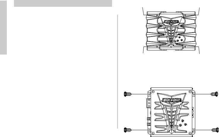
Now that you are ready to mount your amplifier, use the supplied 3mm allen wrench to remove the amplifier EndKaps. This will give you access to the mounting holes in the amplifier and all wiring connections.
NOTE: Objects in the manual are larger than they appear!
Pictures and diagrams of the massive KX2500.1 in this manual are not to scale...this was done to prevent having a manual the size of your average wakeboard.
Remove |
Remove |
With the shroud removed, drill 4 holes using a 7/64” (2.75 mm) drill bit and use the supplied #8 screws to mount the amplifier.
4 |
KX2500.1 Amplifier |
Wiring
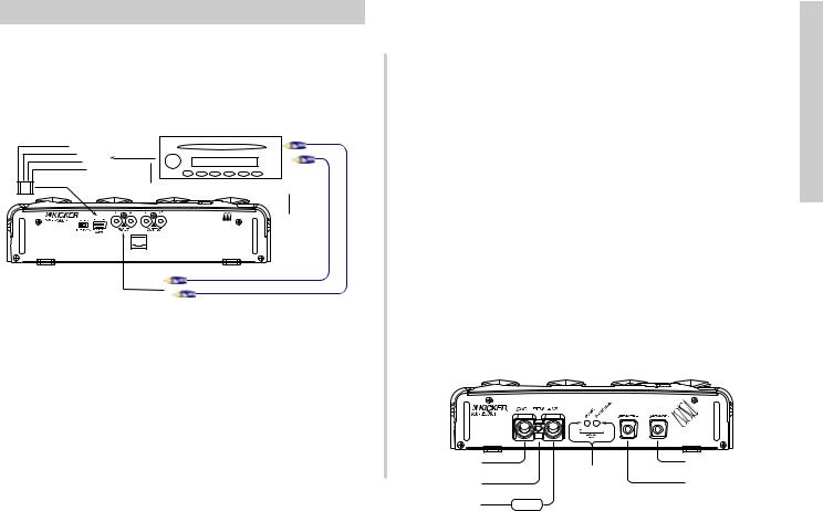
Signal can be input into the amplifier using either the low level RCA input connections or the high level speaker level connections. Using the low level RCA connections is the preferred method. Use the high level inputs only if your head unit does not have low level RCA type outputs. Connecting to the amp with either input will provide a low level signal at the output (PAST) jacks.
Left + |
Speaker |
Left - |
Outputs |
|
|
Right - |
SOURCE UNIT |
Right + |
|
WARNING-Use Only One...Never Both At The Same Time !!!
RCA
Outputs
REMOTE
BASS
The use of twisted pair interconnects is recommended for all installations to minimize noise. When routing these cables through the automobile, try to keep them away from factory wiring harnesses and other power wiring. If you need to cross any of this wiring do so at a 90 degree angle to reduce the possibility for noise problems.
When working with power connections it is always recommended that you disconnect the battery to prevent accidents.
The ground should be connected to the amplifier first before making any of the other connections. This wire should be as short as possible (36 inches or less) and connected to a paint and corrosion free solid metal area of the car’s chassis.
Use the same gauge wire as recommended for the amplifier’s power connection to the battery. Adding an additional ground wire between the car battery’s negative post and the car chassis of this same gauge (or larger) is highly recommended. Adding or upgrading the ground from the case of the alternator to the car chassis is also recommended.
If you ever need to remove the amp from the vehicle after it has been installed, the ground wire should be the last wire disconnected from the amplifier. Just the opposite as when you installed it.
The supplied ANL fuse holder and fuse must be installed within 18 inches of the battery to protect the power wire feeding your amplifier.
The Remote Turn-On lead gets connected to your source unit’s power antenna lead or another switched + 12 volt source in your vehicle.
Model |
Fuse Size |
Wire Gauge |
|
|
|
|
|
|
KX2500.1 |
300 Amp |
1/0 Ga |
To Chassis Ground
|
LED Status |
Remote Turn-On |
Indicators |
|
NOTE 1 |
To + Post On Battery |
FUSE |
To Speaker - Terminal
To Speaker + Terminal
NOTE 1: Supplied with amplifier. 300 amp ANL type fuse with holder. Wire within 18" of the battery.
Installation
KX2500.1 Amplifier |
5 |
 Loading...