


KM Coaxial Speakers
KICKER MARINE SPEAKERS
KM4
KM65
KM8
Owner’s Manual | English
Manual del Propietario | Español
ALTAVOZ COAX KM
Benutzerhandbuch | Deutsch
KM KOAX-SYSTEM
Manuel d’utilisation | Français
HAUT-PARLEURS COAXIAUX KM
2014 KM Coax Rev d.indd 1 |
|
|
11/22/2013 11:44:25 AM |
|
|
||
|
|
|
|

KM Coaxial Speakers
Owner’s Manual
Authorized KICKER Dealer:
Purchase Date:
Speaker Model Number:
The KICKER KM coaxial speakers are specifi cally designed for mounting in free-air applications. The speakers do not require a sealed enclosure for optimum performance. It is important to isolate the sound coming off the front of the driver from the sound radiating from the back of the driver. This isolation is usually accomplished by using the driver in a factory speaker location, or in a location with a semi-isolated rear chamber.
SPECIFICATIONS |
|
|
|
Model: |
KM4 |
KM65 |
KM8 |
Woofer [in, mm] |
4, 100 |
6-1/2, 160 |
8, 200 |
Tweeter [in,mm] |
1/2, 13 |
3/4, 20 |
1, 25 |
Rated Impedance [Ω] |
2, 4 |
2, 4 |
4 |
Peak Power Handling [ Watts] |
150 |
195 |
300 |
Continuous Power Handling [Watts RMS] |
50 |
65 |
150 |
Sensitivity [1W, 1m] |
89 |
90 |
92 |
Frequency Response [Hz] |
60-20k |
35-21k |
30-21k |
Mounting Hole Diameter [in, mm] |
3-13/16, 97 |
5-1/8, 130 |
6-11/16, 170 |
Mounting Depth [in, mm] |
1-7/8, 48 |
2-7/8, 72 |
3-1/4, 82 |
Grilles |
Yes |
Yes |
Yes |
Tweeter Magnet Material |
Neodymium |
Neodymium |
Neodymium |
Tweeter Dome Material |
PEI (polyether imide) |
Titanium |
Titanium |
Tweeter Design |
Balanced Dome |
Dome |
Dome |
Woofer Cone Material |
Polypropylene |
Polypropylene |
Polypropylene |
Woofer Surround Material |
Santoprene |
Santoprene |
Santoprene |
LOCATION
The sound produced by the KM coaxials is directional. Find the best location for stereophonic sound. If necessary, add more KM coaxial speakers to the system to help distribute and balance the sound-stage. After determining the best mounting locations, carefully check the areas where the mounting hardware will be placed.
Pro Tip: You are one KXM Amplifi er and a few cables away from a complete, high-quality system with rock-solid bottom end as only available from KICKER! Please ask your dealer about KICKER KXM amplifi er upgrades.
2
2014 KM Coax Rev d.indd 2 |
|
|
11/22/2013 11:44:33 AM |
|
|
||
|
|
|
|

Possible locations for KM
Coaxial Speaker Mounting
Mounted
Mid-Ship Stern
Mounted
Mounted in the Bow
INSTALLATION
Mounting: Make sure the stainless steel mounting screws and U-type speed clips will not puncture the fuel cell, wiring, or interfere with any mechanical parts on the underside of the mounting surface. Pre-drill the mounting screw holes using a 7/64” (2.5mm) bit, and attach the KM coaxial speakers to the boat by fastening the supplied stainless steel coarse-threaded screws to the boat’s structure. If applicable, use the enclosed stainless steel U-type speed clips. If the supplied hardware is not applicable to your installation, some other means of securely attaching the speakers to the boat must be used.
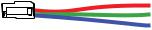
Wiring: Carefully place the speaker wire in a location that is clear of standing water and moving components of the boat. For reference, the Blue wire is Positive and the Grey wire is Negative. The locking terminal cover with water resistant gasket is removable for wiring installation; it helps prevent terminal corrosion and electrical shorting. Connect the gold-plated male quick-disconnect on the end of the 18 inch (46cm) speaker wire leads coming out of the sealed speaker basket to the wires from your amplifi er or source unit. Place the connected wires into the locking terminal, making sure the divider separates the blue and silver wire quick disconnects, and snap the locking terminal cover into place. Connect the other end of the wire to your amplifi er in accordance with its owner’s manual. Mount the locking terminal cover in a location free and clear of standing water by utilizing the supplied zip ties through the integrated loops in the locking terminal cover.
Locking Terminal Cover
Wire Divider
Mount the speaker and grille right side-up to take advantage of the coaxial system’s integrated moisture draining system.
Loops for mounting with Zip Ties
3
2014 KM Coax Rev d.indd 3 |
|
|
11/22/2013 11:44:33 AM |
|
|
||
|
|
|
|
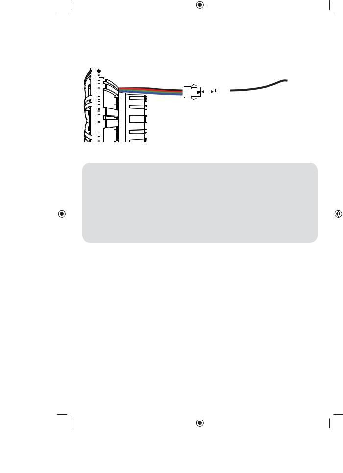
LED Wiring (KM654LCW/KM84LCW only): When hard-wiring the RGB lighting, the black lead is +12V and the red, green, and blue leads are ground. There are seven colors available, depending on your wiring confi guration. KICKER recommends using the KMLC lighting controller (sold separately) for more colors, patterns, and special effects.
+12V
 } Ground
Color Combinations: Splice and combine the ground wires to yield a different color.
Red |
Red |
Green |
Green |
Blue |
Blue |
Red/Green |
Lime Green |
Red/Blue |
Magenta |
Blue/Green |
Aquamarine |
Red/Green/Blue |
Blue-White |
Please E-mail support@kicker.com or call Technical Services at (405) 624-8583 for specifi c or unanswered questions.
Note: KICKER Marine speakers meet or exceed industry standards for environmental humidity and corrosion, and for
material degradation due to UV exposure. All specifi cations and performance fi gures are subject to change. Please visit www.kicker.com for the most current information.
4
2014 KM Coax Rev d.indd 4 |
|
|
11/22/2013 11:44:36 AM |
|
|
||
|
|
|
|
Manual del Propietario
Altavoces Coaxiales KM
Distribuidor Autorizado
KICKER:
Fecha de compra:
Número de modelo de altavoz:
Los altavoces coaxiales KICKER KM están diseñados específi camente para su instalación en aplicaciones al aire libre. Los altavoces no requieren de un gabinete sellado para un desempeño óptimo. Es importante aislar el sonido que proviene del frente del conductor del sonido radiante de la parte posterior del conductor. Este aislamiento se consigue normalmente usando el conductor en una posición de altavoz de fábrica o en una posición con una cámara posterior semi-aislada.
ESPECIFICACIONES |
|
|
|
Modelo: |
KM4 |
KM65 |
KM8 |
Altavoz de baja frecuencia [pulg., mm] |
4, 100 |
6-1/2, 160 |
8, 200 |
Altavoz de alta frecuencia [pulg., mm.] |
1/2, 13 |
3/4, 20 |
1, 25 |
Impedancia especifi cada [Ω] |
2, 4 |
2, 4 |
4 |
Máximo manejo de potencia [Watts] |
150 |
195 |
300 |
Manejo de potencia continua [Watts RMS] |
50 |
65 |
150 |
Sensibilidad [1W, 1m] |
89 |
90 |
92 |
Respuesta de frecuencia[Hz] |
60-20k |
35-21k |
30-21k |
Diámetro de orifi cio de instalación [pulg., mm] |
3-13/16, 97 |
5-1/8, 130 |
6-11/16, 170 |
Profundidad de instalación [pulg., mm] |
1-7/8, 48 |
2-7/8, 72 |
3-1/4, 82 |
Rejillas |
Si |
Si |
Si |
Material de imán de altavoz de alta frecuencia |
Neodimio |
Neodimio |
Neodimio |
Material de domo de altavoz de alta frecuencia |
PEI (poliéter imida) |
Titanio |
Titanio |
Diseño de altavoz de alta frecuencia |
Domo balanceado |
Domo |
Domo |
Material de cono de altavoz de baja frecuencia |
Polipropileno |
Polipropileno |
Polipropileno |
Material envolvente de altavoz de baja frecuencia |
Santoprene |
Santoprene |
Santoprene |
UBICACIÓN
El sonido producido por los coaxiales KM es direccional. Encuentre la mejor posición para un sonido estereofónico. Si fuera necesario, agregue al sistema más altavoces coaxiales KM para ayudar a distribuir y a balancear el escenario de sonido. Después de determinar las mejores ubicaciones de instalación, compruebe cuidadosamente las áreas en donde se colocarán los accesorios de instalación.
Consejo Profesional: ¡Usted está a la distancia de un Amplifi cador KXM y de unos cuantos cables de un sistema de alta calidad con extremo inferior clásico como sólo es posible con KICKER! Pregunte a su distribuidor acerca de las actualizaciones del amplifi cador KICKER KXM.
5
2014 KM Coax Rev d.indd 5 |
|
|
11/22/2013 11:44:36 AM |
|
|
||
|
|
|
|
 Loading...