

Page 1
96M11843
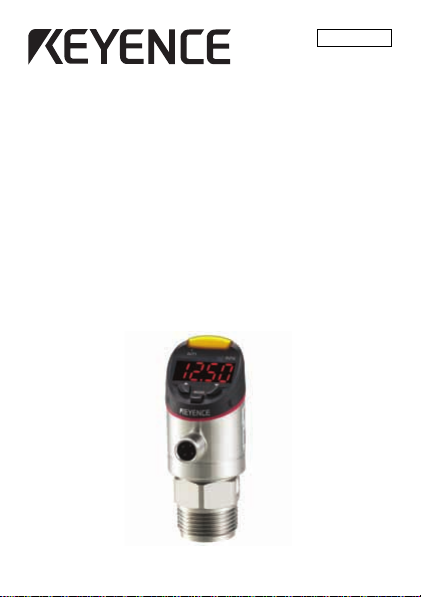
Environment Resisting Type
Built-in-amplifier Pressure Sensors
GP-M Series
Instruction Manual
Read this instruction manual before using the product in order to
achieve maximum performance.
Keep this instruction manual in a safe place after reading it so that it
can be used at any time.
Page 2
Symbols
DANGER
WARNING
CAUTION
NOTICE
Reference
WARNING
In this instruction manual, the following symbols will be used to so
that important points can be understood at one glance.
Be sure to read these messages carefully.
It indicates a hazardous situation which, if not
avoided, will result in death or serious injury.
It indicates a hazardous situation which, if not
avoided, could result in death or serious injury.
It indicates a hazardous situation which, if not
avoided, could result in minor or moderate injury.
It indicates a situation which, if not avoided, could
result in product damage as well as property damage.
It indicates tips for better understanding or useful infor mation.
Safety Information for GP-M Series
1. Do not use this product for the purpose to
protect a human body or a part of human body.
2. This product is not intended for use as an
explosion-proof product. Do not use this
product in hazardous locations and/or
potentially explosive atmospheres.
3. The GP-M Series is not designed to sanitary
specifications. Do not use the product for
applications such as drinks, foods, or medical
liquids.
4. Do not use the GP-M Series for applications
requiring safety measures, such as any
nuclear, railroad, aircraft, vehicle, or
playground equipment.
2
Page 3
1. You must verify that the GP-M Series is
CAUTION
NOTICE
operating correctly in terms of functionality
and performance before the start and
operation of the GP-M Series.
2. We recommend that you take all the necessary
safety measures to avoid any damage in the
unlikely event of a problem occurring.
3. Do not use the GP-M Series with corrosive liquids.
1. We cannot guarantee the functions and/or
performance in the event that the product is
used outside the standards of the
specification, or if the product is modified.
2. When using our product in combination with
another product, based on such factors as
conditions of use and surrounding
environment, sometimes functions and
performance may not be fully realized. In such
a case, use after adequate examination.
Precautions on Regulations and Standards
CE Marking
KEYENCE Corporation has confirmed that this product complies with the
essential requirements of the applicable EC Di rectives, based on the
following specifications. Be sure to consider the following specifications
when using this product in the Member States of European Union.
z EMC Directive (2004/108/EC)
• Applicable standards EMI: EN61326-1, Class A
Remarks
These specifications do not give any guarantee that the
end-product with this product incorporated complies with the
essential requirements of EMC Directive.
The manufacturer of the end-product is solely responsible for the
compliance on the end-product itself according to EMC Directive.
EMS: EN61326-1
3
Page 4
CSA Certificate
CAUTION
NOTICE
GP-M Series complies with the following CSA and UL standards and
has been certified by CSA.
• Applicable standard CAN/CSA C22.2 No.61010-1
Be sure to consider the following specifications when using this
product as a product certified by CSA.
• Overvoltage category: 1
• Use this product under pollution degree 2.
• Use this product at the altitude of 2000 m or less.
• Indoor use only.
• Use CSA/UL certified power supply that provides Class 2 output
as defined in the CEC (Canadian Electrical Code) and NEC
(National Electrical Code), or CSA/ULcertified power supply that
has been evaluated as a Limited Power Source as defined in
CAN/CSA-C22.2 No. 60950-1/UL60950-1.
• Do not use the GP-M Series for poizonous fluid.
Caution when handling
1. When detecting the temperature of the fluid, the
2. The screw part of the main unit is sharp, take
1. Do not drop or hit the device, and avoid any
2. Do not use a sharply pointed object to press
3. If the detection portion is pushed with sharp
UL61010-1
housing of the product will be hot, and there is
the danger of a burn injury. Do not touch the
metal housing while the product is in operation.
care to avoid injury.
other large shock to the device.
the setting keys.
thing, damage may occur to the detection
surface. Also, for devices where the measuring
range is low, the detection portion is thin and
easy to break. Touch as little as possible.
4
Page 5
Precautions for wiring
CAUTION
NOTICE
NOTICE
1. Do not modify or disassemble unnecessarily. It
may cause electric shock or improper operation.
2. Do not work on the wiring with bare hands.
Even if the power is OFF, electric charge may
remain and cause electric shock.
3. Do not work on the pipe work or wiring with
wet hands. It may cause electric shock.
4. When wiring, confirm the pin position.
5. Use the GP-M Series within the rated range.
The GP-M Series is a sensor that uses a DC
(direct current) power source. Do not apply
alternating current or other power supplies. Do
not use a load that exceeds the allowable limit.
1. Use an insulated stabilizing supply for the
power supply.
2. Do not pull strongly on the cable.
3. Ensure that the cable tip is not submersed in
water during wiring work.
4. Isolate the cable from power supply lines or
power lines.
5. Isolate the cable as far as possible from any
source of noise.
Other precautions
1. The power ON reset time for the GP-M Series is
2 seconds after power is turned on. Do not use
outputs from the sensor during this period.
2. Initial drift may occur after supplying power to
the GP-M Series. To detect a minute difference
in the pressure, let the GP-M Series warm up
for approximately 15 to 30 minutes.
3. Do not bring a strong magnet or magnetic field
close to the main body of the GP-M Series.
5
Page 6
4. Do not remove the seal of the air hole of the
NOTICE
GP-M001/M010/M025. It will no longer be
waterproof.
5. When condensation occurs, it may become
impossible to make measurements, or,
damage may occur. Take measures such as
the following to prevent condensation.
• Ensure that the ambient temperature is the same
or lower than the fluid temperature.
• Remove moisture via air conditioning
• Separate the sensor 30 cm or more from the
cooling pipes using the connector pipe.
6. When conducting maintenance, use a soft
brush so as not to damage items such as the
detection surface or the O-Ring.
7. When replacing the O-Ring, clean all of the
debris from the surface that will be in contact
with the O-Ring.
Checking the Packed Items
GP-M001/M010/M025
Sensor x 1
Instruction manual x 1
GP-M100/M250/M400
Sensor x 1
Instruction manual x 1
O-Ring x 1
(OP-87287)
O-Ring set x 1
(OP-87288)
6
Page 7
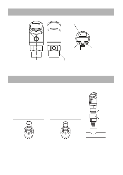
Name and Function of Each Part
1
Connector
for input
cable use
2
Clasp
3 Air hole
*
4 Operating light (output 1)
5 Operating light
(output 2)
8 MODE button
6
UP button
(U)
7 DOWN
button (V)
O-Ring
Adapter
* Only for the GP-M001/M010/M025
Piping/Installation
Piping
• Use the adapter for matching with the
diameter of the piping.
• When using a replacement adapter, attach
the O-Ring included with the Main Unit to the
groove of the G3/4 female screw part.
(Refer to the diagram below)
GP-M001/M010/M025
GP-M100/M250/M400
Adapter
• Inquire to us when connecting the pipes directly using the GP-M
Series with a G3/4 female screw.
• The body may be rotated horizontally to 330°. When rotating,
hold the clasp in place with something such as a wrench.
Adapter
7
Page 8
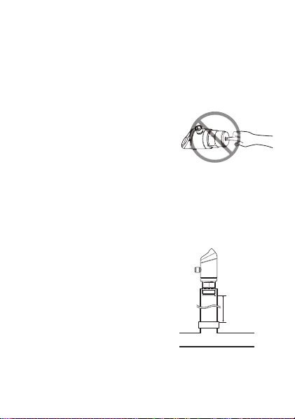
Precautions when installing
Cooling pipe
30 cm or more
z Attaching the coupling
The recommended tightening torque when installing the adapter
to the main body of the sensor is 20 N•m. It is recommended to
apply grease to the G3/4 screw part in order to avoid scorching.
z Grounding of metal parts
The metal parts of the main body, the internal circuits 0 V are insulated.
z Other precautions
• Regardless of whether the power
of the device is ON or OFF, do not
touch the main part of the
pressure detector, if the if the
pressure detector is touched,
damage may occur due to static
electricity.
• If using a non-conductive liquid such as oil, and plastic piping
are used, the risk of an offset change will become greater. In
such a case, it is recommended to ground the metal housing.
• In the case that noise causes malfunction, grounding the
metal housing may improve performance.
• After installation, conduct an atmospheric correction by
making the applied pressure the same as regular room
pressure. (Refer to page 10)
• When there is condensation,
separate the sensor from cooling
pipe by at least 30 cm using the
connecting pipe.
8
Page 9
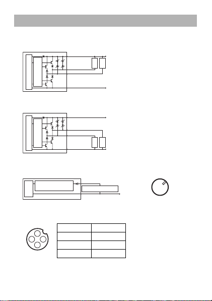
Wiring, Output Diagram
3
2 (Output 2)*
1
10 to 30 VDC
4 (Output 1)
0 V
Overcurrent
protection circuit
Main circuit
Load
Load
3
2
(Output 2)*
1
10 to 30 VDC
4 (Output 1)
0 V
Overcurrent
protection circuit
Main circuit
Load
Load
3
2 4 to 20 mA*
Analog current
output circuit
0 V
Main
circuit
Analog input device
2
3
1
4
Output diagram
z When choosing an NPN output
*
When choosing the function of output 2
QWV
(control output) only.
z When choosing a PNP output
*
When choosing the function of output 2
QWV
(control output) only.
Analog output diagram Pin
2
13
4
* When Choosing
#P.)
of the Function of Output 2 only.
M12 Connector Cable (Optional) Pin Position
1 Brown
2 White
3 Blue
4 Black
9
Page 10

Initial Settings at the Time of Delivery
Push briefly
MODE
Settings finish
2P
Polarity of control output
Select by button.
P2P NPN type
2P2 PNP type
Choose function of output 2
Select by button.
QWV Control output
#P.) Analog output
Alternate
QWV
KQ
P2P
Alternate
Push briefly
MODE
*
MODE
Reference
MODE
Correct the atmospheric pressure
When turning the power ON for the first time after delivery, set the
initial settings according to the outline below.
* On this screen, press the V button 5 times while pressing and
holding the button to move to the unit switch screen “
using UV the unit can be selected from , , ,
(except GP-M100/M250/M400), and (except GP-M001).
Pushing while pushing U
the previous screen.
briefly will return you to
7PKV
”. By
Atmospheric Pressure Correction
Function for correcting the measurement value to 0 due to problems
such as long term use.
Main
Push and
screen
• Always correct the atmospheric pressure by making the applied
• The air pressure correction is effective within a range of ±10 of
hold +
pressure the same as regular room pressure.
F.S. If it is executed outside of that range, “
no correction will occur.
The screen will blink
and the present pressure
will be corrected to 0.
10
” is displayed and
Page 11

• The atmospheric pressure correction will be reflected on the
Activate/Deactivate Key Lock
From the main screen, press and hold the MODE button and
the U button (or the V button) simultaneously.
If “
.QE
” is displayed while blinking, the Key Lock is enabled. With
the same operation it can be disabled (“
WP.
” will be displayed
while blinking).
Reference
Disabling the Key Lock with Password
1. From the main screen press and hold the MODE button
simultaneously with the U button (or the V button).
“
2#55
” and a number value alternately is displayed.
2. Select a password with the UV and press the MODE
button to select.
If the correct password is entered:
“
WP.
” will appear as a blinking display, and Key Lock will be
disabled.
If an incorrect password is entered:
“
'T2
” will appear as a blinking display, Key Lock will not be
disabled, and the screen will return to the main screen.
analog output.
Key Lock
Function for preventing operation error.
• If the Key Lock is enabled, the setting value change (the
detail settings from pressing and holding the MODE
button) is not available. (“
•If “
2#55
” is set to a value other than “
value)” via the extended function (page 16), when
the Key Lock is disabled a password will be
requested. (Refer to below)
.QE
” will display as blinking”)
11
(initial
Page 12

Changing the Setting Value of Output 1
Push briefly
MODE
*4
*2
*3
52
Push briefly
MODE
Switch-on point 1
Select using the buttons.
Setting range: 1% of F.S. to 100% of F.S.
(Details on page 17)
Switch-off point 1
Select using the buttons.
Setting range: 0% of F.S. to
(Switch-on point) -1% of F.S.
(Details on page 17)
Finish settings
Return to main
screen
Alternate
T2
Alternate
Press or briefly
*1
*3. The detection mode of the Output 1 is
displayed as “(.” when in window mode.
*4. If it is not used for 4 seconds it will return
to the main screen.
*1. The detection mode of the Output 1 is
displayed as “(*” when in window mode.
*2. If it is not used for 4 seconds it will return
to the main screen.
Display Pressure Unit
If the MODE button is pressed briefly on the main screen, the
pressure unit will display.
If it is not used for 2 seconds it will return to the main screen.
Display Peak and Bottom H old
If the MODE button + the U (V) button are pressed briefly on
the main screen, the peak (bottom) hold value will display.
(“
2A*
” (“
DA*
”) and hold value will blink alternately.)
Change the setting value of output 1. The changing of setting values
of output 2 is done by pressing and holding the MODE button.
(Refer to page 15)
Display Pressure Unit/Hold Display
12
Page 13

• Peak (bottom) hold value will be stored into
Reference
*
MODE
MODE
EEPROM every 45 seconds.
• If the U and V buttons are pressed and held
simultaneously on the peak (bottom) hold screen, the
peak (bottom) hold value of the initial reset will be cleared.
• To return to the previous screen, press the MODE
button briefly.
Initial Reset (Initialization)
Briefly press the button 5 times while continuously pressing
Alternate
T5'V
MODE
Push briefly
Alternate
2P
MODE
Push briefly
Alternate
KQ
MODE
Push briefly
Finish settings
* On this screen, press the V button 5 times while pressing and
holding the button to move to the unit switch screen “
using UV the unit can be selected from , , ,
(except GP-M100/M250/M400), and (except GP-M001).
If anything other than the default value is selected, and when
is pressed briefly on the
appear.
Initialization Yes/No
PQ
Select using the buttons.
PQ Initialization is interrupted,
returns to main screen.
;'5 All items will be initialized.
P2P
Polarity of Control Output
Select using the buttons.
P2P NPN type
2P2 PNP type
QWV
Select function of Output 2
Select using the buttons.
QWV Control output
#P.) Analogue output
2P
screen, the unit switch screen will
13
7PKV
MODE
”. By
Page 14

Reference
MODE
Pressing and U at the same time will return to the
previous screen.
Initialization Value List
Item Default value (by model)
Model
Unit kPa MPa
SP1/FH1
(Switch-on point 1)
rP1/FL1
(Switch-off point 1)
SP2/FH2
(Switch-on point 2)
rP2/FL2
(Switch-off point 2)
ASP (Analog
point (4 mA))
AEP (Analog
point (20 mA))
ou1 (detection mode of output 1) Hno
ou2 (detection mode of output 2) Hno
CoF (offset correction) No correction
dS1/dr1/dS2/dr2 (direct timer) 0.00 (s)
SPEd (responsiveness) 3 (ms)
Eco (power-save mode) oFF
HYS
(presence of hysterisis when in window mode)
diS.U (display renew cycle) 200 (ms)
diS.r (display inversion) no
PASS (password) 0000
GP-M
GP-M
010
GP-M
025
001
40.0 0.400 1.000 4.00 10.00 16.00
20.0 0.200 0.500 2.00 5.00 8.00
100.0 1.000 2.500 10.00 25.00 40.00
80.0 0.800 2.000 8.00 20.00 32.00
start
-100.0 0.000 0.000 0.00 0.00 0.00
end
100.0 1.000 2.500 10.00 25.00 40.00
Item
Default value (for all models)
14
GP-M
100
GP-M
250
on
GP-M
400
Page 15

Settings of Each Setting Function
Push briefly
MODE
Push briefly
MODE
Push
briefly
MODE
Push
briefly
MODE
Push
briefly
MODE
Push
briefly
MODE
Enhanced Functions
Continue to next page
*2 Detection mode of output 2 is displayed as (.
when in window mode.
4. Switch-off point 2
Select using the buttons.
Setting range: 0% of F.S. to
(Switch-on point) -1% of F.S.
(Details on page 17)
3. Switch-on point 2
Select using the buttons.
Setting range:
1% of F.S. to 100% of F.S.
(Details on page 17)
#'2
6. Analog end point (20mA)
Select using the buttons.
Setting range:
0% of F.S. to 100% of F.S.
(Details on page 18)
Alternate
52
Alternate
Output 2 is analogue
output time
2. Configuration of output 2
Select using the buttons.
*PQ Hysteresis Mode N.O.
*P% Hysteresis Mode N.C.
(PQ Window Mode N.O.
(P% Window Mode N.C.
(Details on page 17)
#52
5. Analog start point (4mA)
Select using the buttons.
Setting range:
0% of F.S. to 100% of F.S.
(Details on page 18)
Alternate
QW *PQ
Alternate
'PF Finish settings
Return to regular screen
Press and hold
button
MODE
Select using the button
'('PF
QW
1. Configuration of output 1
Select using the buttons.
*PQ Hysteresis Mode N.O.
*P% Hysteresis Mode N.C.
(PQ Window Mode N.O.
(P% Window Mode N.C.
(Details on page 17)
Alternate
T2
*PQ
Alternate
Output 2 at time
of control output
*2
*1
*1 Detection mode of output 2 is displayed as (*
when in window mode.
Push
briefly
MODE
Push
briefly
MODE
• Whi le setting any
items you can return
to the main screen
by pressing and
holding the
button.
• Pressing and
U at the same time
will return the
previous screen.
Reference
15
MODE
MODE
Page 16

7. Offset correction
Reference
MODE
MODE
Alternate
Select using the buttons.
Setting range: Present
MODE
value ±10% of F.S.
Push
(Details on page 19)
briefly
8.
Alternate
Push
briefly
Alternate
Push
briefly
Alternate
Push
briefly
Alternate
Push
briefly
Alternate
Push
briefly
ON delay timer of output 1
Select using the buttons.
Setting range:
MODE
0.00 to 50.00 (s)
(Details on page 19)
9.
OFF delay timer of output 1
Select using the buttons.
MODE
Setting range:
0.00 to 50.00 (s)
(Details on page 19)
10.
ON delay timer of output 2
Select using the buttons.
Setting range:
MODE
0.00 to 50.00 (s)
(Details on page 19)
11.
OFF delay timer of output 2
Select using the buttons.
Setting range:
MODE
0.00 to 50.00 (s)
(Details on page 19)
12. Responsiveness
Select using the buttons.
MODE
Setting range: 3 to 5000 (ms)
(Details on page 20)
• While setting any items you can return to the main
screen by pressing and holding the button.
• Pressing and U at the same time will return the
previous screen.
%Q(
F5
FT
*2
*1
F5
FT
52'F
Alternate
'EQ
Q((
MODE
Push
*3
briefly
Alternate
*;5
QP
MODE
Push
briefly
Alternate
FK57
MODE
Push
briefly
Alternate
diS.r
PQ
MODE
Push
briefly
Alternate
2#55
MODE
Push
briefly
'PF Finish settings
Return to main screen
*1 Output 2 when control output
*2 Output 2 when analog output
*3 Only when the detection mode of both output 1
and output 2 are in hysterisis mode.
13. Power save mode
Select using the buttons.
Q(( Power save mode OFF
QP Power save mode ON
(Details on page
20
14. Hysteresis of Window mode,
Yes/No
Select using the buttons.
QP Hysteresis yes
Q(( Hysteresis no
(Details on page
15. Update of measuring value
on display
Select using the buttons.
Update of measuring value 50 ms
Update of measuring value 100 ms
Update of measuring value 200 ms
Update of measuring value 500 ms
Update of measuring value 1000 ms
(Details on page 20)
16. Display rotation
Select using the buttons.
PQ Regular display
;'5 Rotate by 180°
(Details on page
17. Password
Select using the buttons.
Setting range: to
(Details on page 11)
)
17
)
20
)
16
Page 17

Explanation of All Functions
*P%
*PQ
Hysteresis
T2
52
(1) (2) (3)
Detection mode and setting value
The GP-M Series has two types of detection modes which are
described below.
When the selected function of output 2 is
output 1 and output 2 can be set separately.
Hysteresis mode (
Considering
setting value when ON and when OFF.
• When the output is OFF (right
diagram 1), and the measured
value becomes more 52 than it
will turn on (right diagram 2).
• When the output is ON, and the
measuring value becomes less
than T2, it will turn OFF (right
diagram 3).
Window mode (
This mode determines whether the measured value is within or
outside the area of (* to (..
• If the detection value of the
output OFF condition in the right
diagram 1 is more than ((. +
*;5
) or less than (*, it will turn
ON (right diagram2).
• From that condition the measured
value is larger than (* (right
diagram 3), or, less than (., the
right diagram will be OFF.
• If the measured value of the
condition in the diagram on the
right is less than ((* more than (., it will be ON.
*PQ/*P%
5RT2
)
= hysteresis, it is the mode for changing the
(PQ/(P%
)
*;5
) or
QWV
(control output), the
(*
(1) (2) (3)
(.
17
(4) (5)
*;5
*;5
(PQ
(P%
Page 18

If
Reference
* Selection is possible when the selection function of output 2
(control output) is
QWV
.
Output Detection Mode
Switch on
point
Switch off
point
Output 1
when choosing
hysteresis mode
52 T2
Output 2 52
*
T2
*
Output 1
when choosing
window mode
(* (.
Output 2 (*
*
(.
*
Reference
*;5
is fixed at 0.5% of F.S., the presence or absence of hysterisis
can be selected by the extended function (page 16).
The name of the setting values depending on the mode
and output are as follows.
Free range analog output
Set the pressure value for the respective free range analog start
point and end point. The function of the output 2 can be selected at
the time of
#P.)
within the measured range. Operation is as follows.
1. When
• When
becomes 20 mA
• If the measurement value falls below
#52
• If the measurement value rises above
#'2
2. When
• When
becomes 20 mA
• If the measurement value falls below
#'2
• If the measurement value rises above
#52
(analogue output).
#52
<
#'2
#52
becomes
#'2
, output will be up to 3.8 mA
, output will be up to 20.5 mA
#52
>
#'2
#52
becomes
#'2
, output will be up to 20.5 mA
, output will be up to 3.8 mA
When system error (
#52
and
#'2
: 4 mA
: 4 mA
Current
20 mA
4 mA
3.8 mA
Current
20.5 mA
20 mA
'T5
) occurs, 2 mA will be output.
4 mA
18
can be set freely
#52 #'2
20.5 mA
3.8 mA
#52#'2
Measured
value
Measured
value
Page 19

Offset correction
Pressure value
±10%F.S.
Display value
Solid line:
condition at shipping
Reference
Concerning the value at the time of
shipping, there may be as much
as ±10%F.S. offset correction.
This activates in the case of a
margin of error in the displayed
pressure value and the actual
pressure value.
The pressure value after the offset
correction is displayed on the
setting screen and can be adjusted with the UV buttons.
• Offset correction works in conjunction with “Atmospheric
pressure correction”.
•If the UV buttons are pressed and held simultaneously
on the offset correction screen, the offset correction
value and the air pressure correction value will revert to
the condition at shipping (no correction).
Delay timer
The delay timer can be set within the range of 0.00 to 50.00(s)
When the function selection of output 2 is out (control output) the
delay timer for output 1 and output 2 can be set separately.
Setting
item
Concerning the ON delay timer of output 1/output 2. When the
F5/F5
judgment switches from OFF to ON, t he set delay time will elapse.
Concerning the OFF delay time of output 1/ output 2. When the
FT/FT
* The setting of the dS2, dr2 is possible when the function of output 2 is
judgment switches from ON to OFF, the set delay time will elapse.
selected as out (control output).
Meaning
19
Page 20

Time chart
Reference
j
Output
udgment
ON
OFF
Control output
after delay
OFF
ON
F5/F5
(ON delay)
FT/FT
(OFF delay)
Responsiveness
The time until 100% response of the internal judgment value can be
set from within the range of 3 to 5000 (ms).
The response time of the analog output (90% response) will be an
additional 2 ms from this point.
Power Save Mode
When QP is selected, if the key operation does not occur for 15
seconds (Power Save) will be displayed.
The “”at the time of power save display will move from the left to
the right, and the operation indicator will operate normally. To return
the display status to normal, press any key. When there is an error,
regardless of whether power save mode is QP/
displayed.
Q((
, the error will be
Display Renewal Cycle
Set the interval to renew the display contents. When a value is increased,
only for that time the value will continue to be displayed the same. From
after the renewal until the next renewal, the measurement value will be
averaged so as to control fluctuations in the display value. However,
there will be no influence on the control output and the analog output.
Display inversion
When PQ is selected: regular display
When
;'5
is selected: The display will be inverted vertically 180°.
20
Page 21

Error Display and Countermeasures
Error
display
'T%
Q.
W.
'T2
'T'
'T5
Cause Measures
At the time of atmospheric
pressure correction there is
±10% F.S. applied pressure.
There is too much current flowin g
through the control output.
Outside possible display
range (above)
Outside possible display
range (below)
An incorrect password was
entered at the time of the
Key Lock release.
Write/load to EEPROM
error
System error
Return the air to the room
pressure, once again set
the sensitivity setting.
Check the load, and return
to the rated range.
Return to the rated
pressure range.
Return to the rated
pressure range.
Enter the correct
password. If the password
has been forgotten contact
your nearest sales office.
Do an initial reset. If in that
case the problem has not
been fixed please contact us.
Contact the nearest sales office
Output Condition at the Time of Error.
Error
display
'T%
Q.
W.
'T2
'T'
'T5
Output judgment Analog output
Regular operation Regular operation
OFF Regular operation
Operation at the maximum possible display range
Operation at the minimum possible display range
Regular operation Regular operation
Regular operation Regular operation
OFF 2 mA
21
.
Page 22

Specifications (Differs by model type)
GP-M
GP-M
GP-M
GP-M
GP-M
Model
Rated
pressure
Possible
display
range
Allowable
pressure
Burst
pressure
Display
resolution
Fluid type
001
010
025
-100 to
-0.1 to
+100
+1
kPa
MPa
-120.0 to
-0.210 to
+120.0
+1.110
kPa
MPa
400 kPa 4 MPa 10 MPa 30 MPa 50 MPa 50 MPa
1.5 MPa
15 MPa 35 MPa
0.1 kPa
Gas or liquid that will not
corrode the liquid contact
0.001 MPa 0.01 MPa
part
100
-0.1 to
0 to +10
+2.5
MPa
MPa
-0.360 to
-1.00 to
+2.760
+11.00
MPa
MPa
100
MPa
Liquid that will not corrode
the liquid contact part
250
0 to +25
MPa
-2.50 to
+27.50
MPa
100
MPa
GP-M
400
0 to +40
MPa
-4.00 to
+44.00
MPa
100
MPa
Specifications (All model types are the same)
Type of pressure Gage pressure
Repeatability
characteristics
Zero-cut pressure
Box rotation angle Maximum 330°
*1
Precision
Temperature
value
Connection
diameter
*2
G3/4 (Changes to the R1/8 male,
±1.0% of F.S. or less
±0.3% of F.S. or less
±0.6% of F.S./10°C
±0.5% of F.S.
R3/8 male, G1/4 female, NPT1/8 male, and
NPT1/4 male option adapters are available.)
22
R1/4 male,
Page 23

Medium temperature
Rating
Output
Power supply
volta ge
Current
consumption
Display method
Operation display
light
Hysteresis
Control
Response
Environmental
resistance
output
Analog
output
Output 1
control output
Control
Output 2
output
(
replace
-ment
Analog
type
)
output
Ambient
temperature
Relative
humidity
Vibration
Shock
Enclosure
protection
-20 to +100°C (no freezing/condensation)
10-30 VDC, Ripple (P-P): 10% max,
Class 2 or LPS
50 mA or less (when 24 V: 32 mA or less, when
12 V: 48 mA or less. Excluding output)
4 column digital LED red/
Vertical inversion display possible
Operation indicator (output 1) (orange)
Operation indicator (output 2) (orange)
During hysteresis mode: variable
(Difference between switch-on point and
switch-off point is hysteresis)
During window mode: fixed (0.5% of F.S.)
*3 *6
*4
Selectable from 3 to 5000 ms
As above + 2 ms (90% response)
NPN/PNP open collector (Selectable)
30 V or less, Max. 250 mA
Residual voltage for the Main Unit is
1 V or less, N.O./N.C. selectable
4-20 mA, maximum load resistance 500 Ω
(When the electric voltage is more than 20 V)
-20 to +80°C (no freezing/condensation)
35 to 85% RH (no condensation)
IEC60068-2-6 20 G (10 to 2000 Hz
In each direction of X, Y, Z for 2 hours)
IEC60068-2-27 50 G (11 ms
In each direction X, Y, Z 3 times)
*6
IP67
*5
*6
23
Page 24

Pressure port: SUSXM7/
10
20
30
40
50
60
70
80
90
Ambient temperature (°C)
020406080
Relative humidity (%RH)
0
Diaphragm pressure port: Al2O3/O-Ring: FKM
Housing metal portion: SUS304, SUS303
Housing plastic portion: PPSU
Air hole*7: PTFE, nickel-plated brass.
Material
properties
Wette d
part
Other
parts
Applicable cable M12 connector 4 pin
Weight App. 150 g
*1 This is the value when considering linearity + hysterisis + repeatability
in a stable environment of 23°C.
*2 The repeatability, based on consistent conditions, is the difference in
the detection points at the time of fluctuations in the repetition.
When the temperature of the piping exceeds 80°C, do not connect the cable.
*3
*4 Consumption current including output is 0.6 A and under.
*5 The maximum load resistance R will be the values below in response to
the electric voltage E.
When 10-23V: R = (38 x (E-10) + 128) Ω
When 23-30V: R = 622 Ω
*6 Take measures such as the following to prevent condensation.
Ensure that the ambient temperature is equal or lower than the fluid temperature.
•
• Dehumidify using an air-conditioner
• Separate the sensor from the cooling pipe by at least 30 cm using
the connecting pipe.
Also, it is recommended that ambient temperature and relative humidity should
be within the range of the diagonal line depicted in the graph below.
*7 Only for the GP-M001/M010/M025
24
Page 25

Dimensions
(27.5)
44.3
86.7
ø34.2
44.6
ø30
(Two surface width)
27
29.2
2.6
15.4
G3/4 A
Useable length 10
M12 × 1
Detecting element
ø11 depth 1.2 (GP-M001/M010/M025)
ø7 depth 2.9 (GP-M100/M250/M400)
*
* There is no air hole
on the GP-M100/
M250/M400.
(Unit : mm)
ø19.5
ø22.5
1.5
A-A
A
A
ø15
ø8
ø12.8
2.4
A-A
1.9
A
A
O-ring
for GP-M001/M010/M025 use
O-ring set
for GP-M100/M250/M400 use
25
Page 26

Warranties and Disclaimers
(1) KEYENCE warrants the Products to be free of defects in materials and
workmanship for a period of one (1) year from the date of shipment. If
any models or samples were shown to Buyer, such models or samples
were used merely to illustrate the general type and quality of the
Products and not to represent that the Products would necessarily
conform to said models or samples. Any Products found to be
defective must be shipped to KEYENCE with all shipping costs paid by
Buyer or offered to KEYENCE for inspection and examination. Upon
examination by KEYENCE, KEYENCE, at its sole option, will refund the
purchase price of, or repair or replace at no charge any Products
found to be defective. This warranty does not apply to any defects
resulting from any action of Buyer, including but not limited to improper
installation, improper interfacing, improper repair, unauthorized
modification, misapplication and mishandling, such as exposure to
excessive current, heat, coldness, moisture, vibration or outdoors air.
Components which wear are not warranted.
(2) KEYENCE is pleased to offer suggestions on the use of its various
Products. They are only suggestions, and it is Buyer's responsibility to
ascertain the fitness of the Products for Buyer’s intended use.
KEYENCE will not be responsible for any damages that may result from
the use of the Products.
(3) The Products and any samples ("Products/Samples") supplied to Buyer
are not to be used internally in humans, for human transportation, as
safety devices or fail-safe systems, unless their written specifications
state otherwise. Should any Products/Samples be used in such a
manner or misused in any way, KEYENCE assumes no responsibility,
and additionally Buyer will indemnify KEYENCE and hold KEYENCE
harmless from any liability or damage whatsoever arising out of any
misuse of the Products/Samples.
(4)
OTHER THAN AS STATED HEREIN, THE PRODUCTS/SAMPLES
ARE PROVIDED WITH NO OTHER WARRANTIES WHATSOEVER.
ALL EXPRESS, IMPLIED, AND STATUTORY WARRANTIES,
INCLUDING, WITHOUT LIMITATION, THE WARRANTIES OF
MERCHANTABILITY, FITNESS FOR A PARTICULAR PURPOSE,
AND NON-INFRINGEMENT OF PROPRIETARY RIGHTS, ARE
EXPRESSLY DISCLAIMED.
IN NO EVENT SHALL KEYENCE AND ITS AFFILIATED ENTITIES
BE LIABLE TO ANY PERSON OR ENTITY FOR ANY DIRECT,
26
Page 27

INDIRECT, INCIDENTAL, PUNITIVE, SPECIAL OR
CONSEQUENTIAL DAMAGES (INCLUDING, WITHOUT LIMITATION,
ANY DAMAGES RESULTING FROM LOSS OF USE, BUSINESS
INTERRUPTION, LOSS OF INFORMATION, LOSS OR INACCURACY
OF DATA, LOSS OF PROFITS, LOSS OF SAVINGS, THE COST OF
PROCUREMENT OF SUBSTITUTED GOODS, SERVICES OR
TECHNOLOGIES, OR FOR ANY MATTER ARISING OUT OF OR IN
CONNECTION WITH THE USE OR INABILITY TO USE THE
PRODUCTS, EVEN IF KEYENCE OR ONE OF ITS AFFILIATED
ENTITIES WAS ADVISED OF A POSSIBLE THIRD PARTY’S CLAIM
FOR DAMAGES OR ANY OTHER CLAIM AGAINST BUYER.
jurisdictions, some of the foregoing warranty disclaimers or damage
limitations may not apply.
BUYER'S TRANSFER OBLIGATIONS:
If the Products/Samples purchased by Buyer are to be resold or
delivered to a third party, Buyer must provide such third party with a
copy of this document, all specifications, manuals, catalogs, leaflets
and written information provided to Buyer pertaining to the Products/
Samples.
27
In some
E 1101-3
Page 28

Copyright (c) 2011 KEYENCE CORPORATION. All rights reserved.
11843E 1012-1a 96M11843 Printed in Japan
 Loading...