

Page 1
96141E
Digital Fiber Sensor
FS-N10 Series
User's Manual
Read this manual before use.
Keep this manual in a safe place for future reference.
Page 2
Introduction
This manual describes the basic operations and hardware functions of the FS-N10 Series.
Read the manual carefully to ensure safe performance and function of the FS-N10 Series.
Keep this manual in a safe place for future reference.
Ensure that the end user of this product receives this manual.
Symbols
The following symbols alert you to matters concerning the prevention of injury and product
damage.
Provides additional information on proper operations.
Provides advanced and useful information for operation.
Failure to follow the instructions may lead to death or serious
injury.
Failure to follow the instructions may lead to injury.
Failure to follow the instructions may lead to product damage or
failure of the product.
CAUTION
DANGER
WARNING
Reference
Reference
Point
Page 3

Safety Precautions
WARNING
Hints on Correct Use
• Do not use this product in saf ety circuits for human pr otection.
• This product is not ex plosion-proof. Do not use the product in
places with flammable gas, liquid, or dust.
• This product uses DC power. Do not apply AC power. The
product may explode or burn if an AC voltage is applied.
•Do not wire the amplifier line along with power lines or high-tension lines, as the
sensor may malfunction or be damaged due to noi se.
• When using a commercially a vailable switching regulator, ground the frame ground
terminal and ground terminal.
•Do not use the FS series outdoors, or in a place where extraneous light can enter
the light receiving element directly.
•Due to individual dispersion characteristics and the difference in fiber unit models,
the maximum sensing distance or displayed value may not be the same on all
units.
• If the sensor is used for a long time with the APC function enabled and the LED is
imposed with a heavy load, the current consumption of the sensor for light
emission will become constant and 'END APC' will be displayed. The sensor can
still be use
received light intensity should be detected for precise detection.
About UL Certification
The FS-N Series is UL and C-UL certified, and is compliant with the UL and CSA
standards.
•Applicable standardsUL508 Industrial Control Equipment
•UL File No. E301717
• UL categories: NRKH, NRKH7
•Enclosure Type 1 (based on UL50 standard)
Notes on UL Certification
•The power source used with the FS-N Series must be UL Listing certified f or Class
2 output as stipulated by US National Electric Code (NEC) NFPA70.
•Power supply/C ontrol input/Control output shall be connected to a single Class 2
source only.
• Connect the FS-N12
•Use with the over current protection device which is rated 30V or more and not
more than 1A.
d in this case. However, replace the sen
CAN/CSA C22.2 No.14-M05 Industrial Control Equipment
and N14 to the F
S-N11 and N13 main units for use.
sor if even small changes in
96141E
1
Page 4

Safety Precautions
MEMO
2
- Digital Fiber Sensor FS-N10 Series User's Manual -
Page 5
Manual Organization
1
2
3
4
5
6
Before Using
Installation and
Connection
Basic Operation
Settings for
Advanced
Functions
Specifications
Appendix
Outlines the package contents and identifies part
names and functions.
1
Provides procedures for installing sensor amplifiers
and cables, as well as operating precautions.
2
Explains basic instructions for operating and setting
the sensor amplifiers.
3
Describes settings for advanced functions of the
FS-N10 Series.
4
Provides the specifications, circuit diagrams and
dimensions of the FS-N10 Series.
5
Provides the troubleshooting instructions and initial
settings (default values).
6
<Points for Using This Manual>
•
When you
cedures"
•
When you
•
When you
•
When you
•
When you
"Forgot the operation methods"
"Want to try out the FS-N10"
"Want to fully utilize the vari ous functi ons"
"Want to know the meanings of terms used"
"Want to troubleshoot the FS-N10"
- Digital Fiber Sensor FS-N10 Series User's Manual -
or
"Want to find the operation pro-
Go to pages 3-2, 4-2
Go to Chapters 2 and 3
Go to Chapters 3 and 4
Go to Chapter 6 (Index)
Go to Chapter 6 (Troubleshooting)
3
Page 6

Table of Contents
Safety Precautions...............................................................................1
Manual Organization ...........................................................................3
Table of Contents.................................................................................4
Chapter 1 Before Using
1-1 Checking the Package Contents..........................................................1-2
Sensor Amplifier.............................................................................. 1-2
List of Optional Parts....................................................................... 1-2
1-2 Part Names..........................................................................................1-3
Sensor Amplifier.............................................................................. 1-3
Display/control unit..........................................................................1-4
1-3 Model Number Description ..................................................................1-5
1-4 Fiber Units............................................................................................1-6
Chapter 2 Installation and Connection
2-1 Installing Sensor Amplifiers..................................................................2-2
Mounting the Sensor Amplifier........................................................2-2
Wiring Diagrams for Sensor Amplifiers ...........................................2-4
2-2 Connecting the Fiber Unit.................................................................... 2-6
Chapter 3 Basic Operation
3-1 Quick Reference..................................................................................3-2
3-2 Switching Output.................................................................................. 3-4
Output Switch (L-on/D-on) ..............................................................3-4
3-3 Adjusting Sensitivity.............................................................................3-5
List of Sensitivity Adjusting Methods...............................................3-5
Preset Function...............................................................................3-6
Work-Preset Function ..................................................................... 3-7
Maximum Sensitivity Preset Function.............................................3-8
Full Auto Preset Function................................................................ 3-9
Two-point Calibration.....................................................................3-11
Maximum Sensitivity Calibration...................................................3-12
Full Auto Calibration......................................................................3-13
Positioning Calibration...................................................................3-14
Other Calibration Methods ............................................................3-15
3-4 Setting the Current Received Light Intensity to 0 (Zero Shift)............ 3-16
Zero Shift Funct
Operating Principle of the Zero Shift Function.............................. 3-16
4
- Digital Fiber Sensor FS-N10 Series User's Manual -
ion.........
............................................................... 3-16
Page 7

Table of Contents
3-5
Light emission/Received light intensity adjustment (Saturation Canceling)......
Saturation Canceling function.......................................................3-18
3-6 Loading the Recommended Settings (Recipe Function) ...................3-19
Selecting Recipe ...........................................................................3-19
List of Recipes and Recommended Fiber Units............................3-20
3-7 Initialization ........................................................................................3-21
Initialization of Settings (Reset to Initial Values) ........................... 3-21
3-8 Locking in MEGA Mode ..................................................................... 3-22
MEGA Mode Lock (1-Output Type Only)............................ ...........3-22
3-9 Disabling the Key Operation .............................................................. 3-23
Key Lock........................................................................................3-23
Key Lock with PIN Number ...........................................................3-24
Chapter 4 Settings for Advanced Functions
4-1 List of Settings .....................................................................................4-2
4-2 Basic Settings............ ... ................................................................. ......4-4
Power Modes .................................................................... ..............4-4
Sensitivity Setting............................................................................4-4
4-3 Detection Settings (Func)....................................................................4-7
Output Timer.............. ... .................................................................. 4 - 7
Detection Mode... ................................................................. ...........4-8
External Input................................................................................4-17
Writing of External Input to EEPROM................................ ...........4-19
Adjusting Light Emission/Received Light Intensity (Attenuation)
Analog output scaling (FS-N11MN only).............. ... ......................4-21
Analog scaling mode (FS-N11MN only)........................................4-22
4-4 Display Settings (diSP) . .. ... ................................................................ 4-2 3
Display Reverse ............................................................................4-23
Sub Display...................................................................................4-23
Preset Saturation Function............................................................4-28
4-5 System Settings (SYS) .................................................................. ....4-3 0
APC function................................................................................. 4-30
Power Save................................................................................... 4-31
Display Gain............................................................... ...................4-32
Interference Prevention................................................................. 4-33
Common Key-Oper ations Function...............................................4-34
4-6 2-output Settings ( ).............................................................4-35
Detection Mode for Output2..........................................................4-35
Output Timer for Output2 .............................................................. 4-38
4-7 Settings Save/Recall.......................................................................... 4-39
Custom Save (Settings Save) .......................................................4-39
User Reset (Settings Recall).........................................................4-40
3-18
...4-20
- Digital Fiber Sensor FS-N10 Series User's Manual -
5
Page 8

Table of Contents
Chapter 5 Specifications
5-1 Specifications.......................................................................................5-2
1-Output Type.................................................................................. 5-2
2-Output Type.................................................................................. 5-3
Monitor Output Type........................................................................5-4
Zero Line Type ................................................................................5-5
5-2 Input/Output Circuit Diagram ...............................................................5-6
1-Output Type.................................................................................. 5-6
2-Output Type.................................................................................. 5-6
Monitor output type ......................................................................... 5-7
5-3 Dimensions..........................................................................................5-8
Chapter 6 Appendix
6-1 Troubleshooting....................................................................................6-2
Frequently Asked Questions ...........................................................6-2
Error Displays and Corrective Actions.............................................6-5
6-2 Factory Default Setting (Default Value) List .........................................6-6
6-3 List of Recipe Function Settings ..........................................................6-7
6-4 Restrictions on Each Detection Mode..................................................6-9
Restrictions for Sensitivity Settings in Each Detection Mode..........6-9
6-5 Index..................................................................................................6-10
6
- Digital Fiber Sensor FS-N10 Series User's Manual -
Page 9

Before Using
This chapter outlines the package contents and identifies part
names and functions.
1-1 Checking the Package Contents ......... ... ............1-2
1-2 Part Names ........................................................1-3
1-3 Model Number Description................................ . 1-5
1-4 Fiber Units..........................................................1-6
1
- Digital Fiber Sensor FS-N10 Series User's Manual -
1-1
Page 10
1
Reference
1-1
Checking the Package Contents
Before using the unit, make sure that the following equipment and accessories are
included in the package.
We have thoroughly inspected the package contents before shipment. However, in the
event of defective or broken items, contact your nearest KEYENCE office.
Before Using
The FS-N10 Series are amplifier units. Each amplifier unit m ust be used with a
separately sold fiber unit. Select a fiber unit that suits the intended application.
"Fiber Units" (page 1-6)
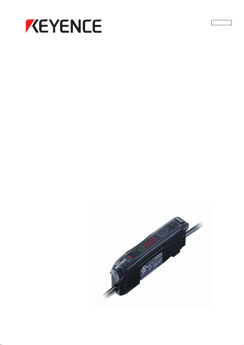
Sensor Amplifier
FS-N10 Series
Sensor amplifier x 1
Instruction Manual x 1
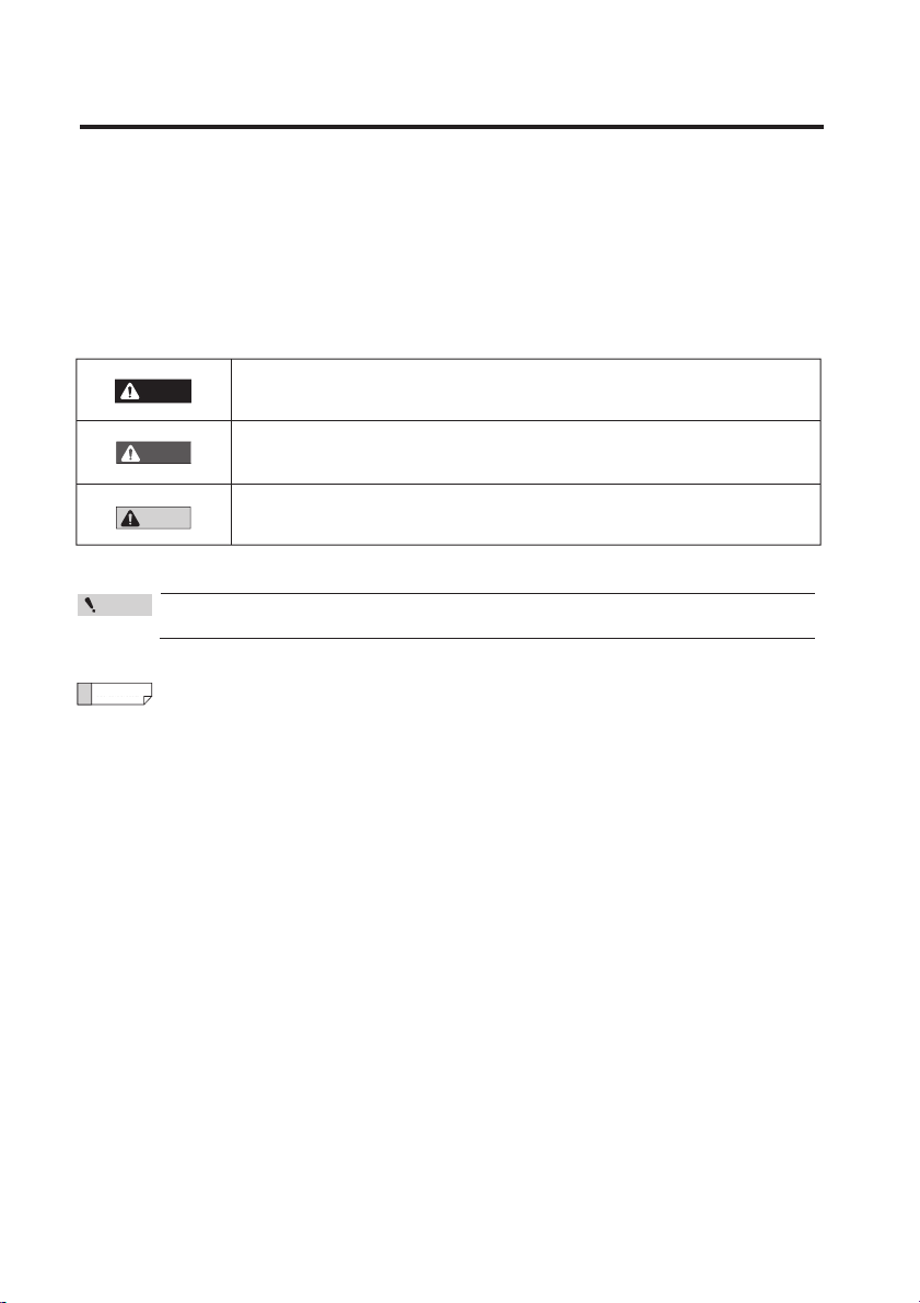
List of Optional Parts
OP-73880
Amplifier mounting bracket
(for main unit) x 1
For information on how to use, refer to
"Installing Sensor Amplifiers" (page 2-2).
OP-73864
M8 connector cable (2 m) x 1
Input/Output cables needed for using the
M8 connector type.
OP-26751
End unit x 2
For information on how to use, refer to
"Installing Sensor Amplifiers" (page 2-2)
OP-73865
M8 connector cable (10m) x 1
Input/Output cables needed for using the
M8 connector type.
Fiber cutter (OP-87098) x 1
OP-87098
Fiber cutter x 1
For information on how to use,
refer to "Connecting the Fiber
.
Unit" (page 2-6).
1-2
- Digital Fiber Sensor FS-N10 Series User's Manual -
Page 11
1-2
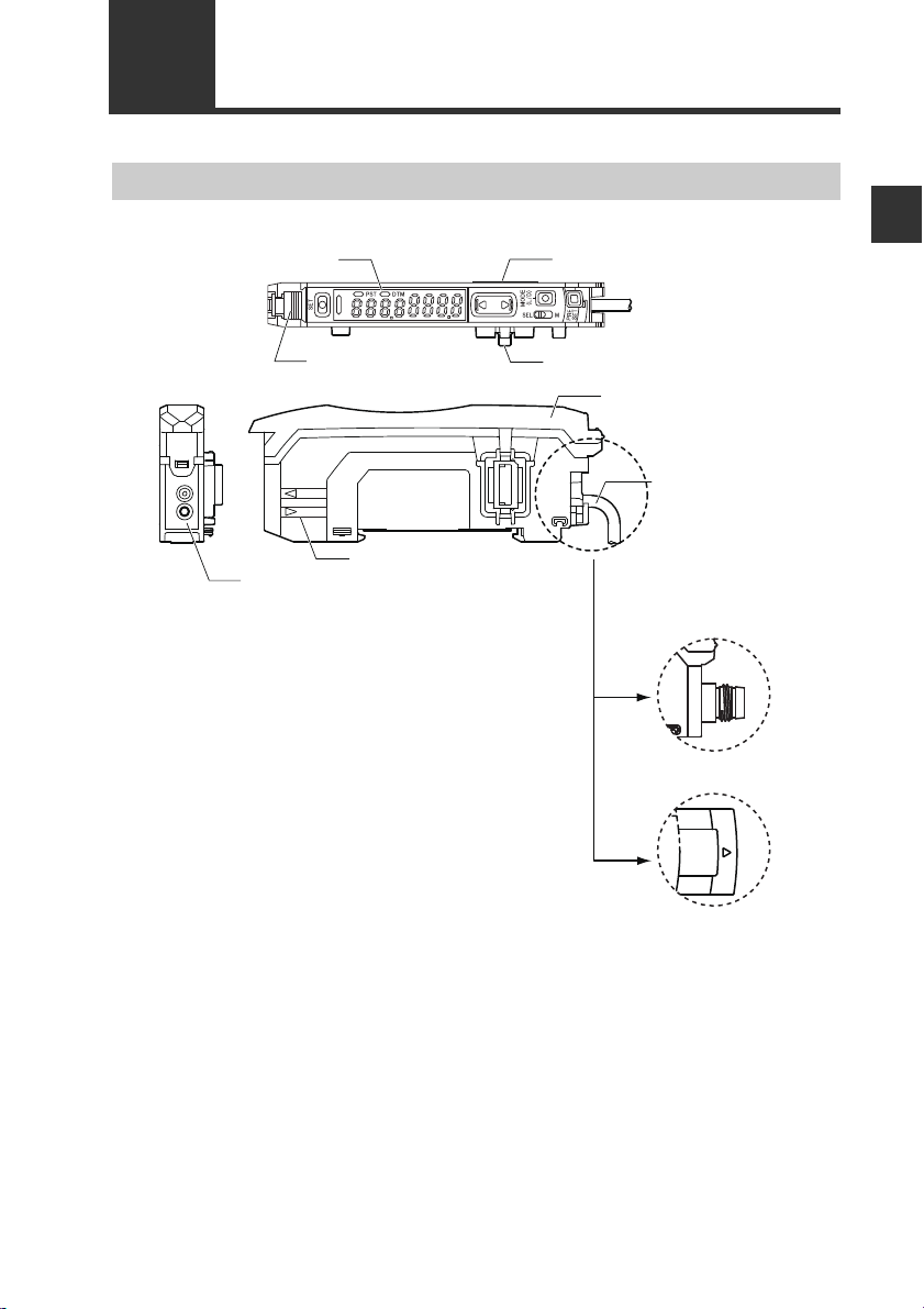
T
R
Connection
Cable
*3
Expansion connector
*1
Display/control unit
Expansion connector
*1*2
Fiber lock lever
Dust cover
Fiber transmit / receive indicators
Fiber connection ports
(FS-N1غ/N1غP)
M8 connector type
(FS-N1
غ
CN/N1غCP)
e-CON connector
(FS-N1
غ
EN)
Part Names
Sensor Amplifier
1
Before Using
*1 Expansion protective cover is installed at the factory prior to shipment.
*2 Not provided on the main unit (FS-N11 □ /N13 □ ).
*3 No connecting cables are provided for the Zero Line type (FS-N10).
- Digital Fiber Sensor FS-N10 Series User's Manual -
1-3
Page 12

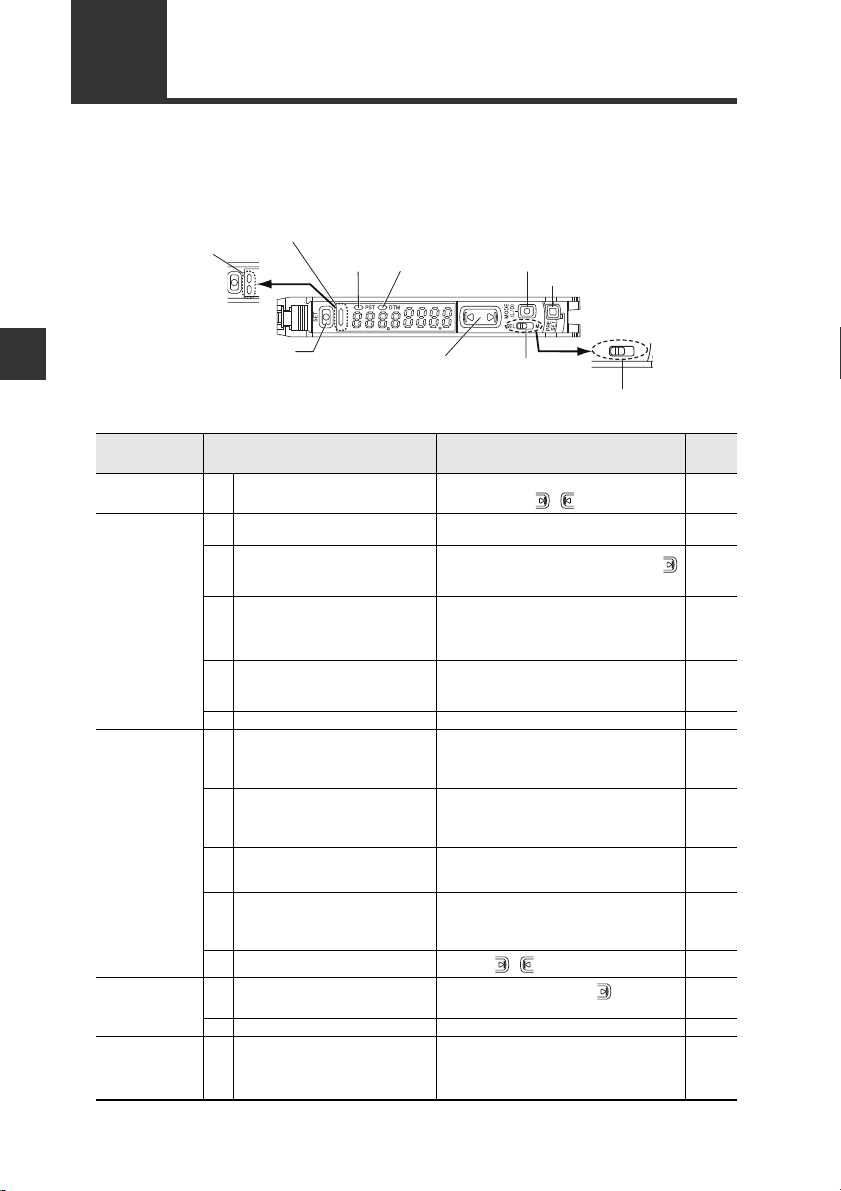
1-2 Part Names
12
Display/control unit
1
1-output type (FS-N11/N12/N11C/N12C/N11EN/N12EN/N11MN/N10)
Before Using
① -1
① -2
②
③
④
⑤
⑥ -1
⑥ -2
⑦
⑧
⑨
⑩
①-2
①-1
②
Item Description
Operation indicator
(1-output/Zero line type)
Operation indicator
(2-output type)
[SET] button
Set value display
(green display)
Current value display
(red display)
Manual button Used to adjust the setting value or select an option.
elect switch
Power s
(1-output type)
Channel toggle switch
(2-output type)
[PRESET] button
[MODE] button
DTM indicator
PST indicator
*
*
⑩
Indicates the current output (detection) status.
Indicates the current output (detection) status of channels 1 and 2
separately.
Use when setting sensitivity, etc.
"Adjusting Sensitivity" (page 3-5)
Displays a sett ing value or advanced setting item in this area of 7segment green indicators.
Displays the current value (received light intensity) and selection
items for detailed settings with red 7-seg ment display.
Changing power modes.
SEL: Allows you to set a power mode using the "Changing Power
M: Fixes the power mode to the "MEGA mode".
"Locking in MEGA Mode" (page 3-22)
Toggles between channels 1 and 2 for configuring the received light
intensity display or sensitivity setting.
Used for presetting or setting values or parameters.
"Preset Function" (page 3-6)
Used for toggling L-on/D-on, proceeding to advanced settings, or
confirming selections.
Lights when a DATUM mode is in effect.
"DATUM1 mode" (page 4-9)
"DATUM2 mode" (page 4-11)
Lights when preset value is set.
"Preset Function" (page 3-6)
⑨
③
④
Modes" function of basic setup.
⑧
⑦
⑥-1
⑤
⑥-2
*Not provided on the Zero Line type (FS-N10).
1-4
- Digital Fiber Sensor FS-N10 Series User's Manual -
Page 13
1-3
FS-N1
(1) (2) (3) (4)
The numbers and letters used in product names are explained below:
Model Number Description
1
(1) Amplifier type
0: Expansion unit (Zero line)
1: Main unit (1-output)
2: Expansion unit (1-output)
3: Main unit (2-output)
4: Expansion unit (2-output)
(3) Cable type
(None): 2-meter cable
C : M8 connector
E: e-CON connector
Model (1) Amplifier type
FS-N11N
FS-N11P
FS-N12N
FS-N12P
FS-N11CN
FS-N11CP
FS-N12CN
FS-N12CP
FS-N11EN
FS-N12EN
FS-N11MN
FS-N13N
FS-N13P
FS-N14N
FS-N14P
FS-N13CP
FS-N14CP
FS-N10
Main unit (1-output)
Main unit (1-output)
Expansion unit (1-output)
Expansion unit (1-output)
Main unit (1-output)
Main unit (1-output)
Expansion unit (1-output)
Expansion unit (1-output)
Main unit (1-output)
Expansion unit (1-output)
Main unit (1-output)
Main unit (2-output)
Main unit (2-output)
Expansion unit (2-output)
Expansion unit (2-output)
Main unit (2-output)
Expansion unit (2-output)
Expansion unit ( Zero line)
(2) Special type
(None): Standard
M : Monitor output
(4) Output type
N: NPN
P: PNP
(2) Special type
Standard
Monitor
output
Standard
−− −
(3) Cable type
2-meter cable
M8 connector
e-CON
connector
2-meter cable
2-meter cable
M8 connector PNP output
(4) Output
type
NPN output
PNP output
NPN output
PNP output
NPN output
PNP output
NPN output
PNP output
NPN output
NPN output
NPN output
PNP output
NPN output
PNP output
Before Using
- Digital Fiber Sensor FS-N10 Series User's Manual -
1-5
Page 14
1
Reference
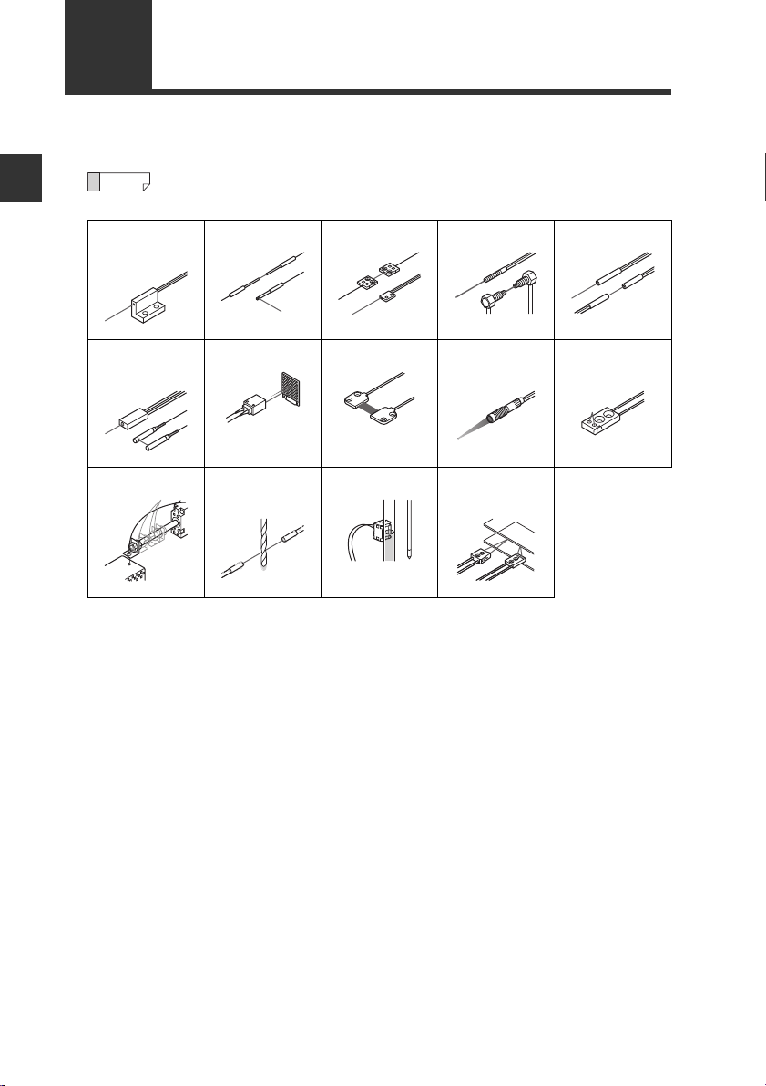
1-4
The FS-N10 Series are amplifier units. They must be used in combination with
separately-sold fiber units.
Before Using
Integrated
bracket
Fiber Units
For fiber unit details, refer to the KEYENCE gener al catalog or contact y our
nearest KEYENCE office.
Sleeve Bracket Threaded Cylinder
Narrow beam/
high power
High-flex Oil/Chemical
Retro-reflectiveArea Small spot
resistant
reflective
Liquid level LCD,
semiconductor
Definite
reflective
1-6
- Digital Fiber Sensor FS-N10 Series User's Manual -
Page 15

Installation and Connection
This chapter provides procedures for installing sensor amplifiers and
cables, as well as operating precautions.
2-1 Installing Sensor Amplifiers................................2-2
2-2
Connecting the Fiber Unit
.........................................2-6
2
- Digital Fiber Sensor FS-N10 Series User's Manual -
2-1
Page 16
2
(3)
(2)
(1)
Reference
WARNING
Installation and Connection
2-1
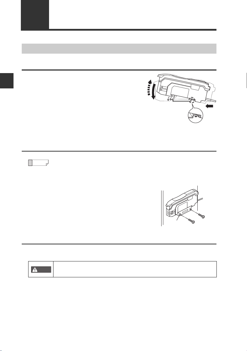
Installing Sensor Amplifiers
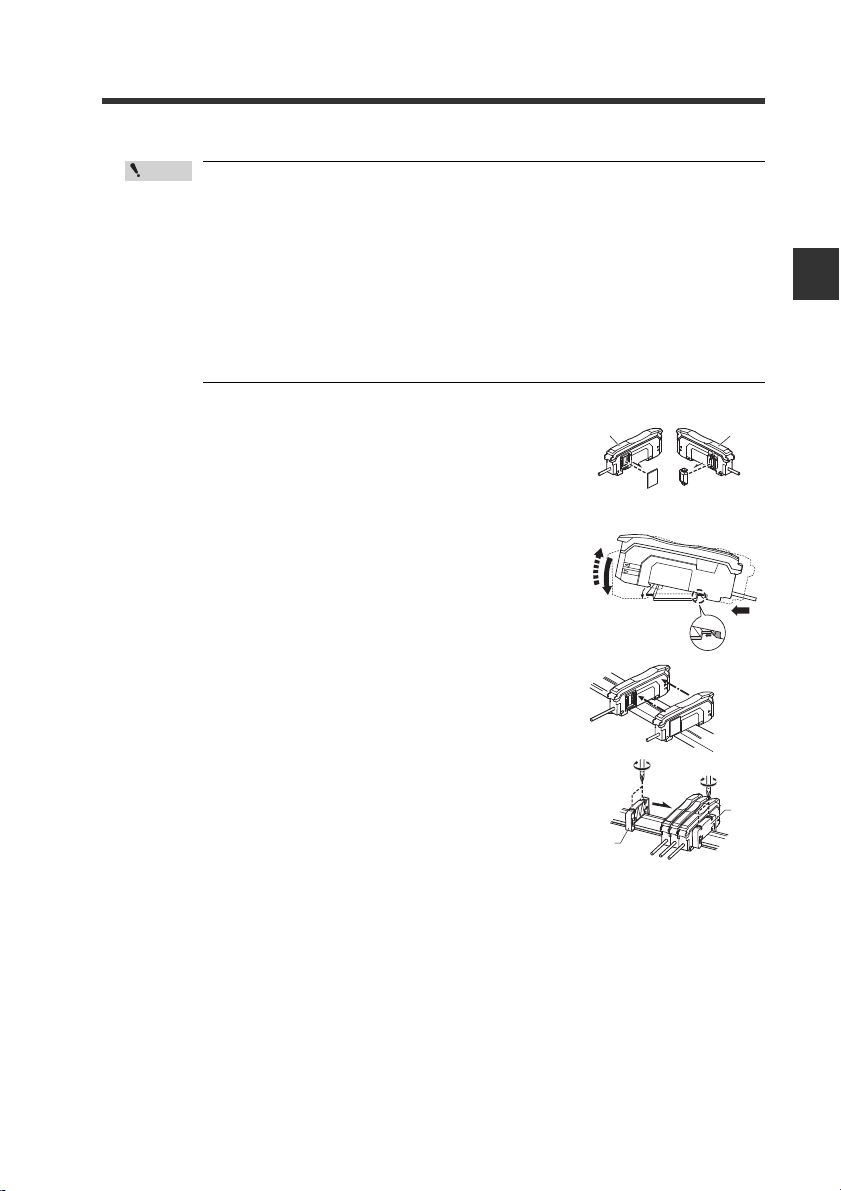
Mounting the Sensor Amplifier
Mounting on a DIN rail
Align the claw at the bottom of the main
1
body with the DIN rail, as shown on the
right.
While pushing the main body in the direction of the arrow (1), push down in the
direction of arrow (2).
T o release the ampl ifier, raise the amplifier
2
body in the direction of arrow (3) while
pushing in the direction of arrow (1).
Installation on a wall
This method applies only when using the main unit independently. If the
main unit is connected with an e xpan sion unit(s), use the method of mounting on a DIN rail.
Mount the amplifier on the amplifier mount-
1
ing bracket (OP-73880, sold separately),
using the same manner as "Mounting on a
DIN rail".
Secure the unit with two M3 screws as
2
shown in the illustration.
Connecting multiple amplifiers
Up to 16 expansion units can be connected to 1 main unit. Note, however, that the
2-output type is considered as 2 expansion units.
Mount on DIN rail and install on metal surface when connecting
multiple amplifiers or mounting main units together.
2-2
- Digital Fiber Sensor FS-N10 Series User's Manual -
OP-73880
Page 17
• Contact your nearest KEYENCE office when connecting a unit
Point
Main unit Expansion unit
(3)
(2)
(1)
other than the N-bus (KEYENCE’s wire-saving system) compatible
sensor amplifier, including FS-N10 Series, or the NU Serie s communication module.
• Turn the power off before connecting multiple expansion units.
• Do not touch the expansion conn ector with your bare hands.
• When using the FS-N10 Series as a main unit, use the products
within the expansion unit’s power voltage range if the power voltage range of the expansion unit is narrower than the FS-N10
Series.
Remove the protection covers from the main unit
1
and expansion unit(s).
Mount the main unit and expansion unit(s) on the
2
DIN rail.
2-1 Installing Sensor Amplifiers
2
Installation and Connection
3
4
5
Slide the main unit and expansion unit(s)
together. Engage the 2 cla ws of the expansion unit
with the recesses on the main unit side until you
hear/ feel a click.
Attach the separately sold end units (OP-26751: a
set of 2 units) to the DIN rail in the same manner
as step (2) (Tightening torque: 0.6N•m or less).
Secure the amplifiers between the end units.
Tighten the screws at the top (2 screws × 2 units)
with a Phillips screwdriver to fix the end units.
- Digital Fiber Sensor FS-N10 Series User's Manual -
End unit
End unit
2-3
Page 18
2
Point
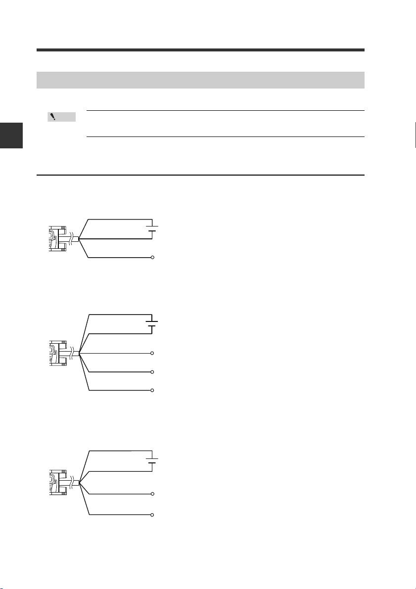
Brown
*
Output
Blue
*
Black
12 to 24 VDC
* FS-N11N/N11P only
Brown
*
Blue
*
Black
12 to 24 VDC
* FS-N13N/N13P only
Output1
External input
Output2
White
Pink
Brown
Blue
12 to 24 VDC
* Connect to a device having an input
impedance 10 kΩ or more.
Black
Output
Monitor output
(
1 to 5V
)
Orange
*
2-1 Installing Sensor Amplifiers
Wiring Diagrams for Sensor Amplifiers
· Be sure to turn off the power before wiring.
· Insulate each input or output cable that will not be used.
Installation and Connection
Wiring Diagrams for Cable Types
1-output type (FS-N11/N12)
2-output type (FS-N13/N14)
Monitor output type (FS-N11MN)
2-4
- Digital Fiber Sensor FS-N10 Series User's Manual -
Page 19
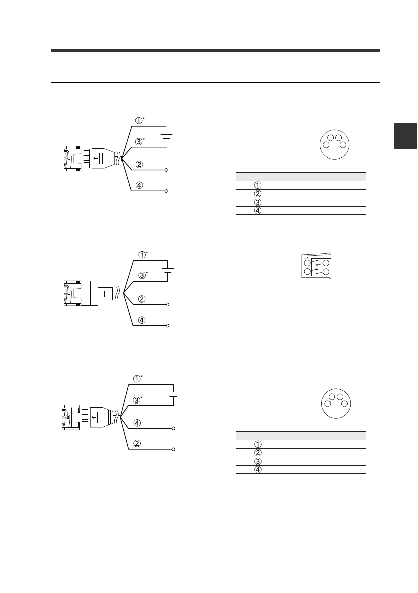
Wiring Diagrams for M8/e-CON Connector Types
12 to 24 VDC
* FS-N11CN/N11CP only
External input
Output
1
2
3
4
M8 connector Pin layout
12 to 24 VDC
* FS-N11EN only
External input
Output
e-CON connector Pin layout
1
2
3
4
12 to 24 VDC
*FS-N13CP only
Output1
Output2
1
2
3
4
M8 connector Pin layout
M8 connector, 1-output type (FS-N11C/N12C)
Pins and wire colors of OP-73864/OP-73865
2-1 Installing Sensor Amplifiers
2
Installation and Connection
Connected pin No.
e-CON connector, 1-output type (FS-N1 1EN/N12EN)
M8 connector, 2-output type (FS-N13CP/N 14 CP )
Pins and wire colors of OP-73864/OP-73865
Connected pin No.
Wire color
Brown
White
Blue
Black
Wire color
Brown
White
Blue
Black
Function
12 to 24 VDC
External input
0V
Output
Function
12 to 24 VDC
Output2
0V
Output1
- Digital Fiber Sensor FS-N10 Series User's Manual -
2-5
Page 20
2
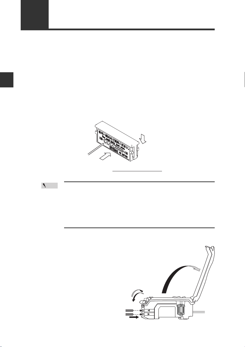
Fiber
(2)
(1)
Always insert fiber from the side with writing
.
Fiber cutter
(OP-87098)
Point
2-2
This section provides procedures for connecting the fiber unit and operating
precautions.
1
Connecting the Fiber Unit
Install the fiber unit.
After the installation, check that the transmitter and receiver of the sensor are
spaced properly. Also check that the optical axis is aligned.
Installation and Connection
If the fiber unit is a free cut type, cut any excess length of the fiber.
2
(1) Insert the fiber into the hole in the cutter.
(2) Bring down the blade in a single, swift motion to cut the fiber.
Failure to observe the cautions belo w may resul t in an impr operly
cut surface, which may reduce the detection distance.
· When cutting the fiber unit, be sure to use a gray fiber cutter
(OP-87098)
· Cut the fiber unit in a single motion without stop ping the b lade
halfway through.
· Do not use the same hole twice.
Open the dust cover in the
3
direction of arrow (1).
Move the fiber lock lever down in
4
the direction of arrow (2).
2-6
- Digital Fiber Sensor FS-N10 Series User's Manual -
(1)
(3)
(2)
Page 21
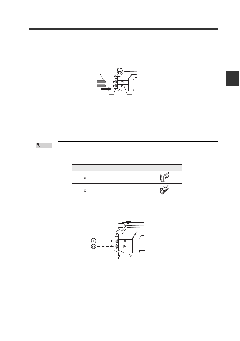
2-2 Connecting the Fiber Unit
Point
Cable outer dia
1.3
1.0
Adapter
AdapterA
(OP-26500)
AdapterB
(OP-26501)
Appearance
Receiver
Position of fiber transmit / receive indicators
Transmitter
Single-core fiber
Multi-core fiber
T
R
Insert the fiber unit into the fiber connection ports on the amplifier.
5
Insert the fiber unit until it reaches the position of the transmit / receive
indicators (approximately 14 mm).
Fiber
2
Fiber connection ports
Move the fiber lock lever ba ck in the direction of arrow (3) to secure the
6
fiber.
· If a thin fiber unit is used, an adapter provided wi th the thin fiber unit
will be required.
Make sure to use the adapter that matches the thin fiber unit.
· To connect a coaxial refl ective fiber unit to the ampl ifier, connect the
single-core fiber to the transmitter (T) side, and connect the
multiple-core fiber to the receiver side (R).
Fiber transmit / receive indicators
Installation and Connection
- Digital Fiber Sensor FS-N10 Series User's Manual -
2-7
Page 22

2
2-2 Connecting the Fiber Unit
MEMO
Installation and Connection
2-8
- Digital Fiber Sensor FS-N10 Series User's Manual -
Page 23

Basic Operation
This chapter explains basic instructions for operating and setting the
sensor amplifier.
3-1 Quick Reference.................................................3-2
3-2 Switching Output................................................3-4
3-3 Adjusting Sensitivity........................................... 3-5
3-4 Setting the Current Received Light Intensity
to 0 (Zero Shift) ................................... ... ... .......3-16
3-5 Light emission/Received light intensity
adjustment (Saturation Canceling)................... 3-18
3-6 Loading the Recommended Settings
(Recipe Function)............................................. 3-19
3-7 Initialization.......................................................3-21
3-8 Locking in MEGA Mode....................................3-22
3-9 Disabling the Key Operation...... ... .. ... ...............3-23
3
- Digital Fiber Sensor FS-N10 Series User's Manual -
3-1
Page 24
3-1
Manual button
[MODE]
button
Power select switch
(1-output type))
[PRESET]
button
[SET] button
Operation indicator
(1-output/Zero line type)
DTM
indicator
PST
indicator
Operation
indicator
(2-output type)
Channel select
switch (2-output type)
Quick Reference
The main setting operations are explained according to purpose. Refer to Chapter 4
for information on advanced function settings and explanations not given below.
3
Basic Operation
Purpose Description Operation procedures
Swiching the
output
Adjusting the
sensitivity and
integrating the
display to "100.0"
and ".0"
Adjusting the
sensitivity
Shifting the
received light
intensity to "0"
Need to prevent
the received light
intensity from
becoming satu-
rated.
3-2
1Swiching the output. (L-on/D-on)
Set the current received light intensity
2
to "100.0". (Preset)
When preset is valid, register the
received light intensity ".0".
3
(Work-preset)
Set the received light intensity slightly
higher than when the setting was
4
made, to "100.0". (Maximum sensitivity
preset)
Automatically register "100.0" and ".0"
when workpiece passes by. (Full Auto
5
preset)
6 Cancel the various preset functions. Press and hold the [PRESET] button. 3-6
Set the setting value at the midpoint
between the received light intensity
7
values when a workpiece is present
and absent. (2-point calibration)
Set the setting value slightly higher
than the received light intensity value
8
at which the setting was made. (Maximum sensitivity calibration)
Set the setting value automatically
9
when a workpiece is passing thro ugh.
(Full auto calibration)
Set the setting value to the base point
10
where the workpiece is positioned.
(Positioning calibration)
11 Finely adjust the setting value directly.
Set the current display to "0". (Zero
12
shift)
13 Cancel the zero shift function. Press and hold the [PRESET] button. 3-16
Automatically adjusts to appropriate
14
light emission and light receiving sen-
sitivity.
- Digital Fiber Sensor FS-N10 Series User's Manual -
*
*
*
1. Press the [MODE] button.
2. Switch with the ( ) button.
Press the [PRESET] button while the PST
indicator is OFF.
After step 7, press the [PR ESET] button +
button in the state to be set as ".0".
While the PST indicator is OFF, press and hold
the [PRESET] button. Reflective model: When
no workpiece is present. Thrubeam/Retroreflective model: When a workpiece is present.
Press and hold the [PRESET] button while the
PST indicator is OFF.
1. Press the [SET] button once when a work-
piece is present.
2. Press the [SET] button once when no work-
piece is present.
Reflective model: Press and hold the [SET] button when no workpiece is present. Thrubeam/
Retro-reflective mo
[SET] butt
on when a workpiece is present.
Press and hold the [SET] button while the
workpiece passes through.
1. Press the [SET] button once when no workpiece is present.
2. Press and hold the [SET] button at the positioning point.
Press the ( ) button.
Press the [PRESET] button + button when
t
he PST indicator
Briefly press [MODE] + [SET] buttons with the
amount of received light in maximum-saturated
condition.
12
del: Press and hold the
is OFF.
Reference
page
3-4
3-6
3-7
3-8
3-9
3-11
3-12
3-13
3-14
1-4
3-16
3-18
Page 25
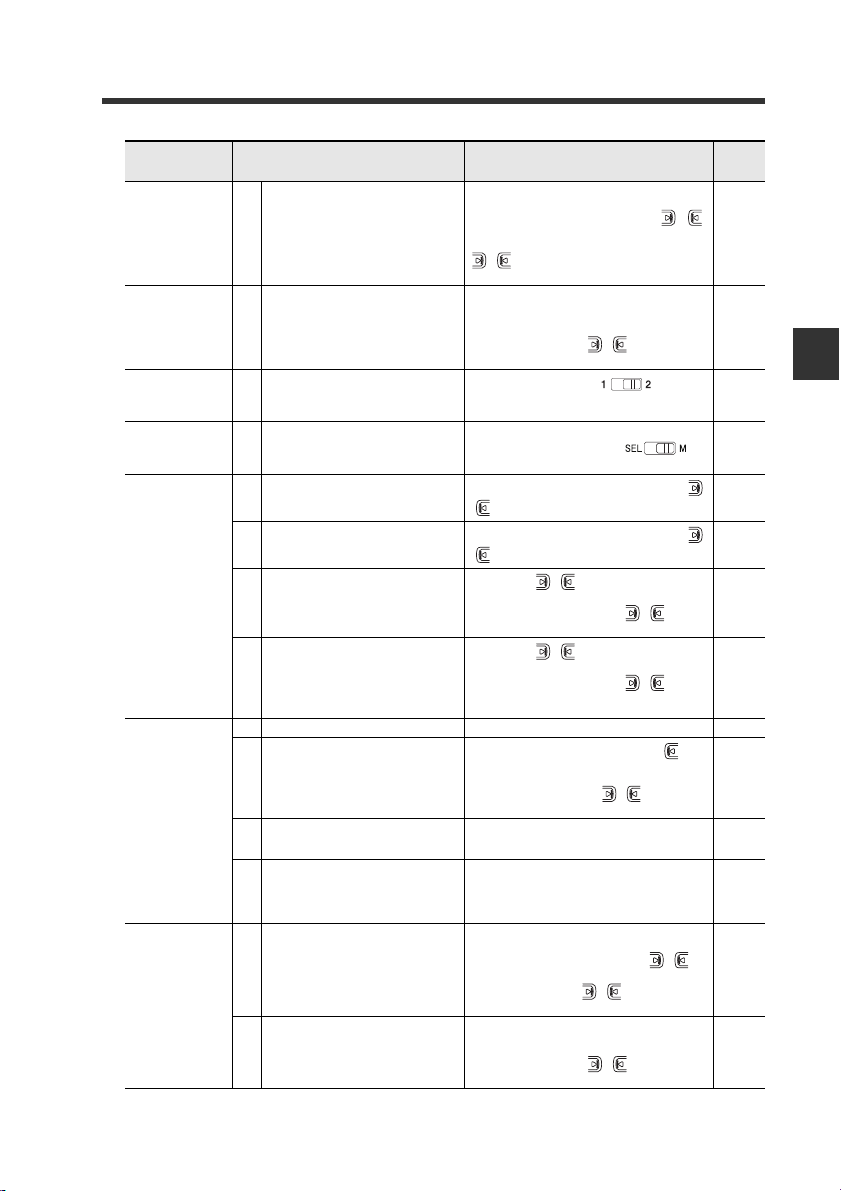
Purpose Description Operation procedures
1. Press and hold the [SET] button and [PRESET] button.
Loading the
recommended set-
tings
Initializing the set-
tings
Displaying the out-
put 2 display
screen with the
2-output type
Switching to the
maximum received
light intensity
power mode
Preventing
incorrect
operations
Others
(Advanced
function settings,
etc.)
Saving and
loading the
settings
Load the recommended settings.
15
(Recipe function)
Initializing (Restore to factory default
16
settings)
17 Switch to the output 2 display screen.
Adjust the power mode to the MEGA
18
mode.
19 Activat
20 Deactivating the key lock
21
22
23 Setting the advanc
24
25
26
27 Saving the settings (custom save)
28 Loading the settings (user reset)
ing the key lock
Activating the password-protected k ey
lock
Deactivating the password-protected
key lock
ed functions Press an
Setting to rescale at each preset execution so that analog output is "5 V"
output in respect to "100.0".
Switching the display to extended display or received light intensity hold
display, etc. (sub-display)
Resetting the following values
* Received light intensity hold value
* Excess gain hold value
* Output when output 2 is in limit setting detection mode
*
2. Display the LoAd screen with the ( )
button, and press the [MODE] button.
3. Select the recipe such as r-1 FALL with the
() button.
4. Press the [MODE] button to execute.
1. Press and hold the [SET] button and [PRE-
SET] button.
2. Press the [MODE] button while on the rSt
screen.
3. Select init with the ( ) button.
4. Press the [MODE] button to execute.
Set the channel switch to .
* The output 2 sensitivity and advanced settings can be modified in this state.
Set the power select s witch to .
Pr
ess and hold the [MODE] button and the
() button simultaneously.
Press and hold the [MODE] button and the
() button simultaneously.
1. Press the ( ) button10 times while
holding down the [MODE] button.
2. Input the password with the ( ) button.
3. Press the [MODE] button to execute.
1. Press the ( ) button 10 times while
holding down the [MODE] button.
2. Input the password with the ( ) button.
3. Press the [MODE] button to deactivate the
key lock.
d hold the [MODE] button. 4-1
1. Press and hold the [MODE] button, but-
ton and [SET] button simultaneously.
2. Press the [MODE] button once or twice.
3. Select "Pr-A PrST" with ( ) button, and
press the [MODE] button.
After setting the sub-display with the advanced
function settings, press the [MODE] button
twice.
Press and hold the [MODE] button and [SET]
button.
1. Press and hold
SET] button.
2. Display the SAvE screen with the ( )
button, and press the [MODE] button.
3. Select yES with the ( ) button.
4. Press the [MODE] button to execute.
1. Press and hold the [SET] button and [PRE-
SET] button.
2. Press the [MODE] button on the rSt screen.
3. Select USEr with the ( ) button.
4. Press the [MODE] button to execute.
the [SET] button and [PRE-
3-1 Quick Reference
Reference
page
3-19
3-21
4-35
3-22
3-23
3-23
3-24
3-24
4-22
4-23
4-25
4-36
4-39
4-40
3
Basic Operation
* Not available for the FS-N10 Series shipped before March 10, 2011.
- Digital Fiber Sensor FS-N10 Series User's Manual -
3-3
Page 26

3-2
Point
Switching Output
Output Switch (L-on/D-on)
This function configures when the output turns ON.
When the current received light inten-
1
sity is displayed, press the [MODE] button.
3
Basic Operation
The current output condition (L-on or Don) is displayed.
Press the button to switch the out-
2
put condition, and then press the
[MODE] button.
Select "D-on" if you want to output the ON
signal when the beam is blocked (a workpiece is present.) for a thrubeam or retro-reflective model.
Select "L-on" if you want to output the ON signal when the beam is received (a
workpiece is present.) for the reflective model.
The output condition is switched, and the current received light intensity is dis-
*2
played.
*1 If you do nothing for 3 seconds or more or press the [MODE] button, the received
light intensity display is automatically restored.
*2 When using the sub-display, the screen will switch between the current received
light intensity L-on/D-on screen sub-display current received light intensity
and so forth each time the [MODE] button is pressed.
"Sub Display" (page 4-23)
• Area detect mode, rising edge detect mode, and falling edge detect
mode are selectable by n.o./n.c.
"Area detection mode" (page 4-14)
"Edge detection mode" (page 4-16)
• When using a 2-output type, output can be individually selected
with channel 1/2.
*1
3-4
- Digital Fiber Sensor FS-N10 Series User's Manual -
Page 27
3-3
Adjusting Sensitivity
This manual refers to the values that select ON/OFF output of the sensor amplifiers as
"Set values." In addition, the manual refers to the adjustment of set values as "Adjusting
Sensitivity." This section describes the sensitivity adjusting method.
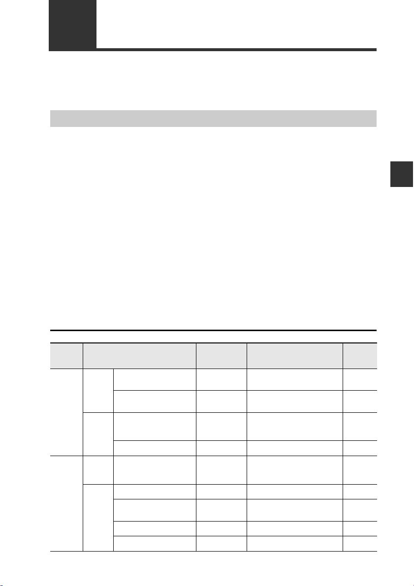
List of Sensitivity Adjusting Methods
Sensitivity adjusting method for the FS-N10 Series is broadly divided into two categories:
① Preset
Simple operation allows sensitivity adjustment concurrently with correction of the
received light intensity to "100.0" or "0.0"
This function helps preventive maintenance by eliminating dispersion of the received
light intensity due to the contents of detection or individual workpieces.
However, this is not suitable for detection of transparent workpiece because there is a
small difference in the received light intensity between presence and absenc e of a
workpiece.
② Calibration
Sensitivity can be adjusted by a simple operation. This function does not correct t he
received light intensity.
This function is applied for using the received light intensity without correction or for
high-precision detection.
Calibration is also available in a preset state.
How to select sensitivity adjusting method
3
Basic Operation
Sensitivity
adjusting
method
Preset
Calibration
Basics
At times
like this
Basic
At times
like this
Status of use Functions Contents Reference
Using thrubeam/retro-reflective
models
Using reflective model
Not successfully displaying the
intensity level as "100.0" and
".0" depending on the presence
of a workpiece.
Mobile object moves fast
ing thrubeam/retro-reflective
Us
models
Mobile body moves fast
Using the unit in the environ-
ment that tends to get dirty
easily.
Using the unit for positioning
Using the unit for
sion detection
high-preci-
Preset
Preset to maximum sensitivity
Work preset
Full automatic
preset
Two-point
calibration
Full automatic
calibration
Maximum sensitivity calibration
Positioning calibration
Percentage calibration
When there is no workpiece, by simply pressing the PRESET button,
sensitivity adjustment is completed.
When there is no workpiece, by simply holding the PRESET button,
sensitivity adjustment is completed.
The status in which "100.0" or ".0" is
displayed can be set at your choice
Preset is enabled by using a f ast-
rkpiece.
moving wo
The setting can be established just
by pressing the [SET] button once
when a workpiece is present and
absent.
Calibration is enabled by using a
fast-moving workpiece.
The setting seldom causes malfunc-
tion even in the environment that
tends to get dirty easily.
The setting suitable f
available.
Effective for making correction from
external devices such as PLC.
or positioning is
- Digital Fiber Sensor FS-N10 Series User's Manual -
3-6
3-8
3-7
3-9
3-11
3-13
3-12
3-14
3-15
3-5
Page 28

3
Green PST lights up
Setting value
is
"50.0"
Current value is
"
100.0"
Workpiece
3-3 Adjusting Sensitivity
Preset Function
Enabling the preset function
When the PST indicator is not lit, press the [PRESET] button.
The PST indicator lights
in green. The current
value is set to "100.0"
and the setting value is
set to "50.0".
Basic Operation
Disabling the preset function
When the PST indicator is lit, press and hold the [PRESET] button.
• The PST indicator turns off, indicating that the preset function has been disabled.
• Once the preset function is disabled, the setting value is recalculated while
retaining the ratio of the setting value and received light intensity.
3-6
- Digital Fiber Sensor FS-N10 Series User's Manual -
Page 29
3-3 Adjusting Sensitivity
Impotant
100.0
[PRESET]+
3.0
.0
Work-Preset Function
This function calibrates the current value to ".0". After the preset function has been
executed with "100.0" displayed, and then executing this function wit h ".0" displayed, 2
random set points can be calibrated to "100.0" and ".0".
* Not available for the FS-N10 Series shipped before March 10, 2011.
Enabling the work-preset function
The work-preset function can be used with the preset function (when
preset is enabled).
While the preset function is enabled, press the [PRESET] button and button
simultaneously.
The received light intensity
at that point is set to ".0".
The value set to "100.0" using
the preset function does not
change.
Green "PST"
lights up
Current value is ".0"
Reference
Even if the received light intensity is low during preset and is high during
work-preset, the value is set to "100.0" during preset and ".0" during work-
preset. When the actual received light intensity increases, the display will
approach ".0". (The preset saturation level is decreased with respect to
"100.0".)
3
Basic Operation
Disabling the work-preset function
When the PST indicator is lit, press and hold the [PRESET] button.
• The PST indicator turns off, indicating that the work-preset function has been
disabled.
- Digital Fiber Sensor FS-N10 Series User's Manual -
3-7
Page 30
3-3 Adjusting Sensitivity
Workpiece
Setting value
Setting value
Thrubeam Model/Retro-reflective Model
Reflective Model
Received light intensity Received light intensity
No workpiece
With workpiece
No workpiece*
With workpiece*
1
1
Saturation point
"100.0"
"50.0"
".0"
"100.0"
"50.0"
".0"
Saturation point
* Where detection occurs on a target having a background, the maximum sensitiv-
ity setting ignores the background. Maximum sensitivity setting is not available if
the background is more reflective than the workpiece.
Point
Maximum Sensitivity Preset Function
This function calibrates the reference state to ".0" and the state at which the received
light intensity is slightly higher as "100.0".
This function is useful with the reflective model to detect while using the background
as a reference.
* Not available for the FS-N10 Series shipped before March 10, 2011.
Enabling the maximum sensitivity preset function
3
Basic Operation
When no workpiece is present for the
1
reflective model, or when a workpiece
is present for thrubeam model/retroreflective model, press and hold the
[PRESET] button for 3 seconds or more
while the PST indicator is OFF.
Release the button when "
Calibration is complete after the setting
value flashes momentarily, and then stops
(lights up).
The PST indicator lights in green, and the
setting value is set to "
50.0
".
• When th e amount of the light received is in saturated state (at a
value higher than at the time of extended display on page 4-30),
maximum sensitivity preset function cannot be implemented.
("---- ----" is indicated when operating 1.)
"Light emission/Received light intensity adjustment (Saturation
Canceling)" (page 3-18)
Auto
" flashes.
Disabling the maximum sensitivity preset function
When the PST indicator is lit, press and hold the [PRESET] button.
• The PST indicator turns off, indicating that the maxi mum sensitivity preset func-
tion has been disabled.
3-8
- Digital Fiber Sensor FS-N10 Series User's Manual -
Page 31

3-3 Adjusting Sensitivity
Setting
value
MAX
MIN
Time
Received
light intensity
The area near the maximum value
of the received light intensity while
the [PRESET] button is pressed is
set as "100.0", and the area near
the minimum value is set as ".0".
1
2
"100.0"
"50.0"
".0"
Point
Full Auto Preset Function
This function automatically judges 2 states (workpiece presence/absence, etc.), and
calibrates the current value to "100.0" and ".0".
This is useful when the detector is moving at high speed, etc.
* Not available for the FS-N10 Series shipped before March 10, 2011.
Enabling the full auto preset function
When the PST indicator is OFF, con-
1
tinue pressing the [PRESET] button
until "Auto" flashes while the workpiece passes through.
Workpiece
After the workpiece has completely
2
passed through, release the [PRESET]
button.
Calibration is complete after the setting
value flashes momentarily, and then
stops (lights up).
The PST indicator lights in green, and the
setting value is set to "50.0".
3
Basic Operation
• When the received light intensity is in a saturate d conditio n (more
than the amount specified in "Display Gain" (page 4-32).), full-automatic preset function is disabled. ("---- ----" will appear during
step 2.)
"Light emission/Received light intensity adjustment (Satura tio n
Canceling)" (page 3-18)
- Digital Fiber Sensor FS-N10 Series User's Manual -
3-9
Page 32

3
Point
Reference
3-3 Adjusting Sensitivity
Disabling the full auto preset function
When the PST indicator is lit, press and hold the [PRESET] button.
• The PST indicator turns off, indicating that the full auto preset function has been
disabled.
Basic Operation
• Each preset function cannot be used when the following functions
are set. Disable the function or change the setting before e xecuting
the preset function.
• Zero shift function → "Zero Shift Function" (page 3-16)
• Zero shift calibration → "Adjusting Sensitivity" (page 3-5)
• Zero shift input → "External Input" (page 4-17)
• DATUM 1/2 mode → "Restrictions for Sensitivity Settings in
Each Detection Mode" (page 6-9)
• Rising/falling edge detection mode" → "Restrictions for Sensitivity Settings in Each Detection Mode" (page 6-9)
• The preset function is not suited for transparent workpieces such
as thrubeam/retro-reflective models and other cases of detection
with low light intensity differences.
• After changing any of the following settings, disable each preset
function once and then execute again.
"Power Modes" (page 4-4)
"Preset Saturation Function" (page 4-28)
"Display Gain" (page 4-32)
• If the received light intensity raw value is 50 or less (200 or less
when the light intensity is set to FuLL), the display will be "100.0" or
less when the preset function is executed.
3-10
• If the [PRESET] button is pressed when the preset function is enabled
(PST indicator is lit), the current received light intensity changes to
"100.0" and the setting value does not change.
• Expansion units can be preset with operations from the main unit.
"Common Key-Operations Function" (page 4-34)
• Periodic presetting is possible with signals input from an external source.
"External Input" (page 4-17)
• With the preset function, a process is carried out to ignore minute
received light intensity changes which do not affect the detection. The
change amount to be ignored can be adjusted randomly.
"Preset Saturation Function" (page 4-28)
• If the sub-display is changed to "Extension", the original received light
intensity can be confirmed even when using the preset function.
Extension → "Sub Display" (page 4-23)
- Digital Fiber Sensor FS-N10 Series User's Manual -
Page 33

3-3 Adjusting Sensitivity
g
Two-point Calibration
Two-point calibration is the most basi c m e th od of sensitivity setting.
The setting value can be established by simply pressing the [SET] button once each
when a workpiece is present. and when it is absent.
Press the [SET] button once
1
when no workpiece is present.
Press the [SET] button once
2
when a workpiece is present.
Calibration is complete after
the setting value flashes
momentarily, and then stops
(lights up).
Press the button to adjust
the setting value.
Workpiece
3
Basic Operation
Reference
Step 1 or step 2 may be performed first.
When performing two-point calibration on channel 2 of the 2-output type,
set the channel switch to " ".
li
Received
ht intensity
* If the difference between the 2 conditions is too small, "- - - -" flashes
1
Setting
value
2
after calibration is complete.
However, the setting value will still established.
- Digital Fiber Sensor FS-N10 Series User's Manual -
The setting value is set to the middle
of the values at which the [SET] button
was pressed first and pressed second.
Time
3-11
Page 34

3
Workpiece
Reference
Setting value Setting value
Thrubeam Model/Retro-reflective Model
Reflective Model
Received light intensity Received light intensity
No workpiece
With workpiece No workpiece*
With workpiece*
1
1
* Where detection occurs on a target having a background, the maximum sensi-
tivity setting ignores the background. Maximum sensit ivity setting is not avail-
able if the background is more reflective than the workpiece.
3-3 Adjusting Sensitivity
Maximum Sensitivity Calibration
This sensitivity setting method is useful if the received light intensity is reduced by
dust or dirt.
The setting value is calibrated to be slightly than the light intensity received when it is
determined.
1
Basic Operation
When a workpiece is absent for the
reflective model, or when a workpiece
is present for the thrubeam model/
retro-reflective model, press and hold
the [SET] button for 3 seconds or
more.
Release the button when "SEt" flashes.
Calibration is complete after the setting
value flashes momentarily, and then stops
(lights up).
Press the button to adjust the setting
value.
When performing two-point calibration on channel 2 of the 2-output type,
set the channel switch to " ".
3-12
- Digital Fiber Sensor FS-N10 Series User's Manual -
Page 35

3-3 Adjusting Sensitivity
Workpiece
g
Full Auto Calibration
This method automatically sets sensitivity using a moving workpiece.
Sensitivity can be easily set by passing a workpiece without shutting down operating
equipment.
While the workpiece passes through,
1
press and hold the [SET] button until
"SEt" flashes.
After the workpiece has completely
2
passed through, release the [SET] button.
Calibration is complete after the setting
value flashes momentarily, and then
stops (lights up).
3
Basic Operation
Reference
• If detection is not stable after the setting operation, for example due to
vibration, press the button to adjust the setting value.
• When performing two-point calibration on channel 2 of the 2-output type,
set the channel switch to " ".
li
Received
ht intensity
MIN
1
- Digital Fiber Sensor FS-N10 Series User's Manual -
2
MAX
Setting
value
Time
The setting value is determined
as the middle value between the
maximum and minimum light
intensity received values
obtained while holding down the
[SET] button.
3-13
Page 36

3
Workpiece
Reference
g
Calibration is complete after the setting value flashes momentarily, and then
stops (lights up).
The setting value is determined as the value of light intensity received when
the workpiece comes into position.
3-3 Adjusting Sensitivity
Positioning Calibration
This method is used when you want to position a workpiece.
1
Basic Operation
2
Press the [SET] button
once when no workpiece
is present.
Position a w orkpiece such
that its edge aligns with
the center of the projecting beam. Then, press
and hold the [SET] button
for 3 seconds or more.
Release the button when
"SEt" flashes.
Press the button to
adjust the setting value.
When performing two-point calibration on channel 2 of the 2-output type,
set the channel switch to " ".
li
Received
3-14
ht intensity
Setting
value
2
1
- Digital Fiber Sensor FS-N10 Series User's Manual -
Time
Page 37

3-3 Adjusting Sensitivity
Point
Other Calibration Methods
Percentage calibration
A setting value is established with a percentage in respect to the current received light
intensity. When a sensor amplifier equipped with an external input is used,
percentage tuning can be performed from an external device, such as PLC, allowing
highly accurate detection of transparent workpieces and small workpieces, etc.
Refer to "Sensitivity Setting" (page 4-4) for details.
Zero shift calibration
This sensitivity setting performs the zero shift function and basic calibration (two-point
calibration / maximum sensitivity calibration / full auto calibration) simultaneously.
The lower of the received light intensity values specified at the time of sensitivity
setting will automatically be set to "0".
Refer to "Sensitivity Setting" (page 4-4) for details.
Percentage calibration and zero shift calibration cannot be set with
channel 2 of the 2-output type models.
3
Basic Operation
- Digital Fiber Sensor FS-N10 Series User's Manual -
3-15
Page 38

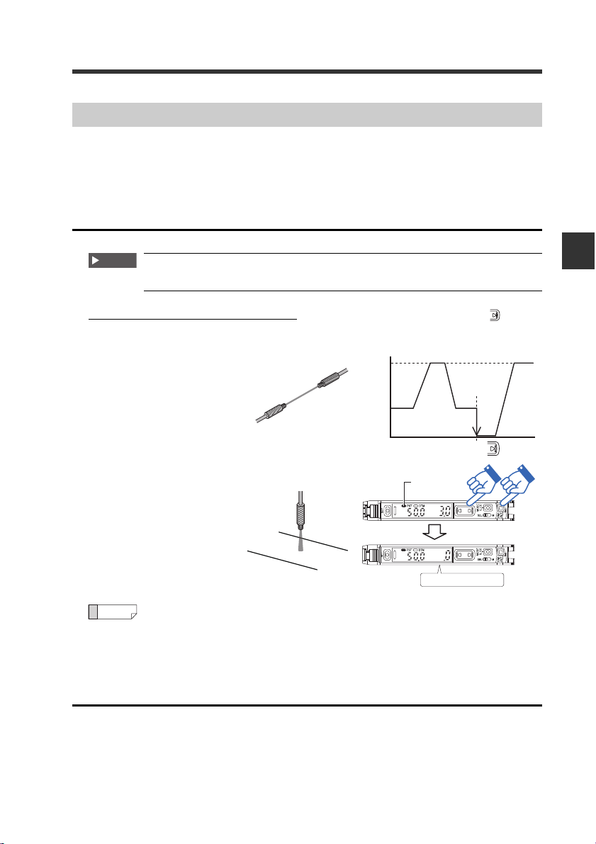
3-4
Green "PST" lights up
Current vallue is "
0
"
0
Received light intensity
Without workpiece
(Background is detected)
200
300
400
450
650
0
Received light intensity
100
200
250
450
Setting the Current Received Light Intensity to 0 (Zero Shift)
Zero Shift Function
This function adjusts the current received light intensity display to "0". It is primar ily
used with reflective sensor heads. If the received light intensity cannot be set to "0"
when a reflective model is installed, this function can be used to set the received light
intensity to "0" with no workpiece present. This makes the difference in received light
intensity easier to distinguish.
3
Basic Operation
Enabling the zero shift function
When the PST indicator is off, press
1
the [PRESET] button and button
simultaneously.
The PST indicator lights in green, and the
received light intensity changes to "0".
Disabling the zero shift function
Press and hold the [PRESET] button.
1
The PST indicator turns off, indicating that the zero shift function has been disabled.
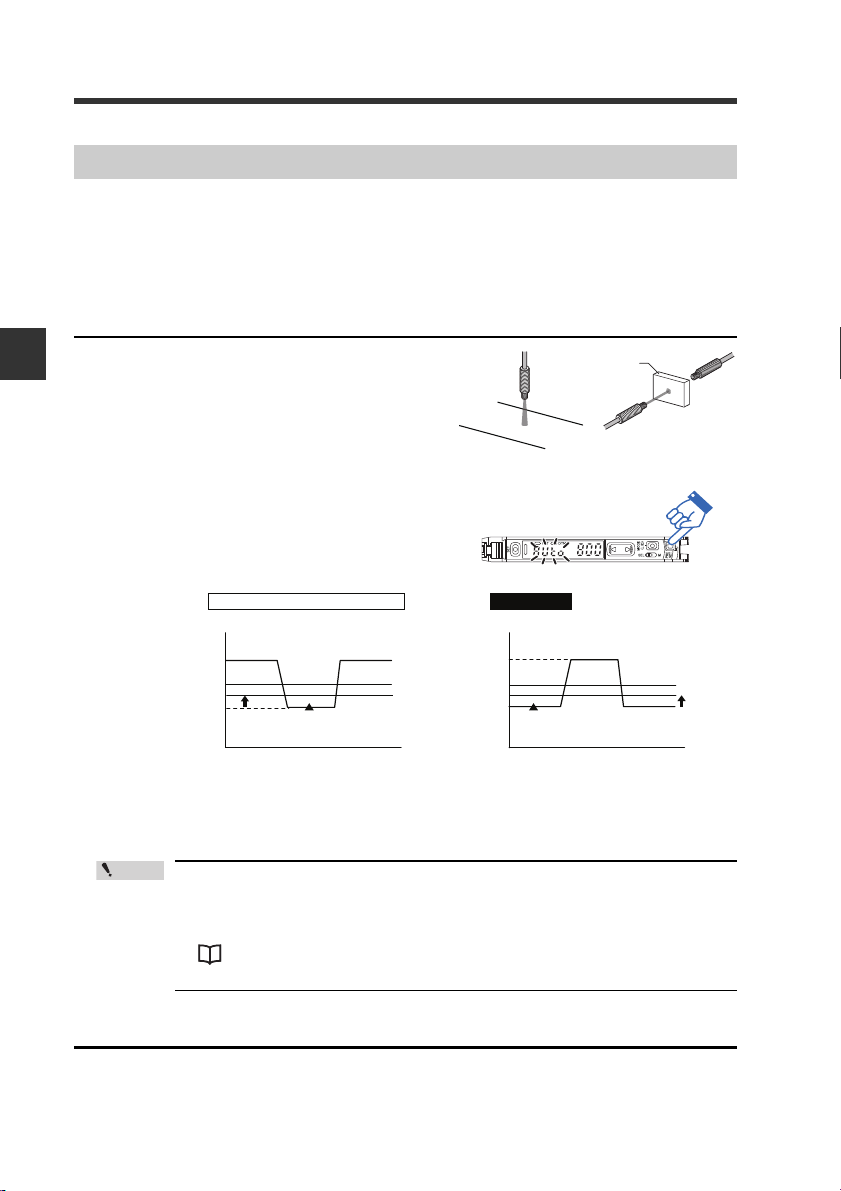
Operating Principle of the Zero Shift Function
< For reflective models >
In applications for d istinguishing colors or
for detecting objects on a background,
the received light intensity will not be "0"
even when no workpiece is present.
3-16
Applying zero shift input to the lo wer
- Digital Fiber Sensor FS-N10 Series User's Manual -
level of received light intensity (with
no workpiece present) enhances
the detection display visibility.
Page 39

3-4 Setting the Current Received Light Intensity to 0 (Zero Shift)
Point
The zero shift function cannot be used in combination with the preset
function. To use the zero shift function, make sure that the preset
function is disabled (the PST indicator is not lit).
Reference
Zero shift of the expansion unit can be set from the main unit.
"Common Key-Oper ations Function" (page 4-34)
3
Basic Operation
- Digital Fiber Sensor FS-N10 Series User's Manual -
3-17
Page 40

3
3-5
When a fiber unit having strong power (longer detection range) is used at a close
range, the received light intensity may remain unchanged from the maximum value in
the display-enable d range (saturated) regardless of whether a workpiece is present or
not. (Example: Numerical value does not change from 9999)
In such a case, the light emission and the received light intensity can be automatically
corrected to optimal state by using the saturation Canceling function.
Light emission/Received light intensity adjustment (Saturation Canceling)
Saturation Canceling function
■ Enabling the saturation Canceling function
Basic Operation
Press the [SET] button while holding down the [MODE] button.
1
The received light intensity corresponding to the power mode is set within the
range as shown in the following table.
Power mode
HSP、FINE、TURBO
SUPER 4095±500
ULTRA、MEGA
■ Disabling the saturation Canceling function
Press the [SET] button while holding down the [MODE] button.
1
3-18
- Digital Fiber Sensor FS-N10 Series User's Manual -
Setting range of
received light intensity
2047±350
5000±600
Page 41

3-6
Point
The FS-N10 Series has the recommended settings (recipe) programmed in advance
according to the fiber unit and applications.
Selecting Recipe
Loading the Recommended Settings (Recipe Function)
When a recipe is loaded, all settings other than those registered in the
recipe are returned to the default values. Complete all other settings
after loading the recipe.
3
Press and hold the [SET] and [PRE-
1
SET] buttons simultaneously for 3
seconds or more.
The "rSt" display flashes.
Press the button to display
2
"LoAd", and press the [MODE] button.
Press the button to select a
3
desired recipe, and press the [MODE]
button.
After the settings are loaded, the screen displays "LoAd oK", which is then
replaced with the current received light intensity.
Basic Operation
- Digital Fiber Sensor FS-N10 Series User's Manual -
3-19
Page 42

3-6 Loading the Recommended Settings (Recipe Function)
Reference
List of Recipes and Recommended Fiber Units
3
Basic Operation
Recipe
Fall detection
r-1 FALL)
(
Percentage
calibration
r-2 SEtP)
(
Reflective
background
cancellation
r-3 0SEt)
(
Full light
intensity
(
r-4 MEGA)
Area detection
(
r-5 ArEA)
0-DATUM*
(
r-6 0dtM)
Recommended
units
Thrubeam model
Thrubeam model
Retro-reflective
model
Reflective model
Reflective model
*
Area model
(FU-E11/E40)
Retro-reflective
model
Description
To detect a falling workpiece.
The falling edge of the received light intensity is
detected, and output as one-shot.
The received light intensity hold value can be confirmed by pressing the [MODE] button twice on the
output 1 screen.
To use the external input and periodically compensate for the reduction in received light intensity due
to contamination on sensor head face.
A decrease in the light-ON mode's received light
intensity can be detected and output to an external
source by using the 2-output type's output 2.
To use the external input and "0" the light intensity
received without a workpiece present.
The background received light intensity is set as 0
even when calibrating with the buttons on the display.
(Zero Shift calibration)
To 0 the lower of level received light intensity values
in order to display higher values of received light
intensity.
The display can be extended up to 5 digits by pressing the [MODE] button twice on the output 1 screen.
This is recommended when outputting within a specific received light intensity range. When the [SET]
button is pressed once at the reference received light
intensity, the upper/lower setting value limits will be
set at ±10% from the reference received light intensity.
This is recommended when detecting a transparent
workpiece. The received light intensity at the state
with no workpiece is set as ".0", and the displayed
value is increased as the amount of light blocked by
the workpiece increases.
When the [SET] button is pressed or when calibrated
with external inputs, the received light intensity -5%
at that point is set as the setting value.
* Not available for the FS-N10 Series shipped before March 10, 2011.
Refer to "List of Recipe Function Settings" (page 6-7) for the details on the
items set with recipe loading.
3-20
- Digital Fiber Sensor FS-N10 Series User's Manual -
Page 43

3-7
Initialization of Settings (Reset to Initial Values)
The sensor amplifier can be reset to the factory default settings.
1
Initialization
Press and hold the [SET] and [PRESET] buttons simultaneously for 3
seconds or more.
The "rSt" display flashes.
3
Press the [MODE] button.
2
Press the button to display
3
"init".
Press the [MODE] button.
4
After the settings are initialized, the
screen displays "oK", which is then
replaced with the current received light
intensity.
Reference
Refer to "Factory Default Setting (Default Value) List" on page 6-6.
Basic Operation
- Digital Fiber Sensor FS-N10 Series User's Manual -
3-21
Page 44

3
Reference
Basic Operation
3-8
Locking in MEGA Mode
MEGA Mode Lock (1-Output Type Only)
This function is available for the 1-output type models (FS-N11 / N12) only.
The sensor amplifier can be locked in MEGA mode, such that it always operates in
MEGA mode regardless of the power mode selected in the basic setup.
"Power Modes" (page 4-4)
Slide the power select switch to the
1
"M" side.
Sliding the power select switch back to
the "SEL" side restores the power mode
that was set before sliding the power
select switch to MEGA mode.
• When the amplifier is locked in MEGA mode, the power mode may not
be changed in the basic setup, as indicated by the flashing of "Loc".
"Power Modes" (page 4-4)
•Likewise, when the amplifier is in the key locked state, the power mode
may not be changed, as indicated by the flashing of "Loc".
"Key Lock" (page 3-23)
3-22
- Digital Fiber Sensor FS-N10 Series User's Manual -
Page 45

3-9
Disabling the Key Operation
Key Lock
The key lock functi on di s ables all key operation to prevent unauthorized use.
Activating key lock
Press and hold the [MODE] button and
1
(or ) simu ltaneously f or 3 seconds
or more.
3
The screen displays "Loc", disabling key
operation and displaying the current
received light intensity.
Deactivating key lock
Press and hold the [MODE] button and
1
(or ) simu ltaneously f or 3 seconds
or more.
The screen displays "unL", enabling key
operation.
Reference
• The key operations on the expansion unit can be locked from the main
unit.
"Common Key-Operations Function" (page 4-34)
•By using the network unit NU series, key locks which could only be dis-
abled via the network can be set. This function allo ws y ou to c hange onl y
the necessary settings with a PLC and touch panel. Refer to the NU
Series User's Manual for details.
Basic Operation
- Digital Fiber Sensor FS-N10 Series User's Manual -
3-23
Page 46

3
Point
3-9 Disabling the Key Operation
Key Lock with PIN Number
A PIN number can be set when activating key lock. Only users knowing the PIN
number can operate the unit.
Activating key lock with a PIN number
Press (or ) 10 times while holding
1
down the [MODE] button.
Basic Operation
The screen displays "Loc 0".
Press the button to set a desired
2
number (up to 4 digits).
Press the [MODE] button.
3
The screen displays "Loc", disabling key
operation and displaying the current
received light intensity.
Deactivating key lock with a PIN number
Hold down the [MODE] button while
1
pressing (or ) 10 times.
The screen displays "Loc 0".
Press the button to specify the
2
PIN number, and then press the
[MODE] button.
The screen displays "unL", enabling key
operation.
3-24
If the PIN number is lost, contact your nearest KEYENCE office.
- Digital Fiber Sensor FS-N10 Series User's Manual -
Page 47

Settings for Advanced Functions
This chapter describes settings for advanced functions of the
FS-N10 Series.
4-1 List of Settings....................................................4-2
4-2 Basic Settings.....................................................4-4
4-3 Detection Settings (Func)...................................4-7
4-4 Display Settings (diSP).....................................4-23
4-5 System Settings (SYS)..................................... 4-30
4-6 2-output Settings ( )........................... 4-35
4-7 Settings Save/Recall........................................4-39
4
- Digital Fiber Sensor FS-N10 Series User's Manual -
4-1
Page 48

4-1
MODE
MODE
MODE
MODE
StGStGStG-
SET
1234
1234
1234
1234
1234
1234
Std
SEtP
OSEt
END
FuNc
DiSP
SYS
SET
SET
MODE
Press and hold for 3 seconds or more
FINE mode
TURBO mode
SUPER mode
ULTRA mode
MEGA mode
HIGH SPEED mode
Normal sensitivity setting method
Percentage Calibration*
1
Zero-shift calibration
Settings complete
Go to detection setup mode
Go to display setup mode
Go to system setup mode
Return to normal display
Fine
TurB
SuPR
ULTR
MEGA
hSP
…(page 4-4)
…(page 4-5)
…(page 4-6)
…(page 4-4)
…(page 4-4)
…(page 4-4)
…(page 4-4)
…(page 4-4)
…(page 4-4)
MODE
*
7
Settings complete
Go to display setup mode
Go to system setup mode
Return to detection
setup mode
Normal (light intensity)
detection mode
DATUM1 mode *
3
Timer OFF
Off-delay timer *
2
On-delay timer *
2
One-shot timer *
2
DATUM2 mode *
3
Area detection mode
Rising Edge Detection Mode
Falling Edge Detection Mode
External input off
External calibration input
Preset input
Zero shift input
Reset input
Light transmission OFF input
Pause function *
4
Sleep function
Return to normal display
Adjusting light emission/received light
intensity (Attenuation)
*5
*
8
Analog scaling
*6
Alternate
display
…(page 4-7)
…(page 4-8)
…(page 4-9)
…(page 4-14)
…(page 4-16)
…(page 4-16)
…(page 4-17)
…(page 4-17)
…(page 4-17)
…(page 4-17)
…(page 4-17)
…(page 4-17)
…(page 4-18)
…(page 4-19)
…(page 4-7)
…(page 4-7)
…(page 4-7)
…(page 4-21)
…(page 4-11)
…(page 4-20)
Normal display method
Reverse display
Settings complete
Go to system setup mode
Go to detection setup mode
Return to display setup mode
Sub-display off
Extension display
Bar display
Excess gain (%) display
Light intensity hold display *
9
Excess gain hold (%) display *
9
L-on / D-on display
Disable the saturation of the
Preset function
Enable the saturation of the
Preset function *
10
Return to normal display
…(page 4-23)
…(page 4-23)
…(page 4-23)
…(page 4-24)
…(page 4-24)
…(page 4-25)
…(page 4-25)
…(page 4-27)
…(page 4-27)
…(page 4-28)
…(page 4-28)
*11
Settings complete
Go to detection setup mode
Go to display setup mode
Return to system setup mode
Normal operation
Twice the number of
interference-prevention units as
STD
(response time 2 times slower)
Disable Eco Function
Enable Eco Function
Reduce power consumption
(response time 4 times slower)
Disable common key operations
Enable common key operations
APC function is disabled
APC function is enabled
Standard current value display
Maximum current value display
(4 times hysteresis)
Return to normal display
…(page 4-31)
…(page 4-31)
…(page 4-32)
…(page 4-32)
…(page 4-33)
…(page 4-33)
…(page 4-34)
…(page 4-34)
…(page 4-31)
…(page 4-30)
…(page 4-30)
List of Settings
Basic Settings…(page 4-4)
4
Settings for Advanced Functions
Detection Settings (Func)…(page 4-7)
4-2
Display Settings (diSP)…(page 4-23)
System Settings (SYS)…(page 4-30)
- Digital Fiber Sensor FS-N10 Series User's Manual -
Page 49

4-1 List of Settings
Light intensity detection mode
Limit setting output mode *
13
Warning output mode
Timer OFF
Off-delay timer *
2
On-delay timer *
2
One-shot timer *
2
Settings complete
Return to normal display
…(page 4-38)
…(page 4-36)
…(page 4-37)
…(page 4-38)
…(page 4-38)
…(page 4-38)
…(page 4-38)
MODE
MODE
MODE
MODE
MODE
MODE
MODE
MODE
*12
…(page 4-35)
2-output Settings ( )
*1 You can press the button to set between the range of -99P and 99P.
*2 Press the button to set between the range of 1 and 9999 (ms).
*3 Press the button to set the adjustment sensitivity to a range of between LEu1 and LEu3 and set the warning output level to a range of
between 0P and 100P.
*4 Press the button to switch between oFF/on/KEEP.
*5 Pressing the button enables you to set to the range within 1 to100.
*6 The analog output upper limit can be set between 50 and 65535.
*7 FS-N11
*8 Mon
itor output type only (FS-N11MN Only).
*9 Press the button to toggle between Std/P~P_/b~b_/P_b~/P~b_.
*10 Press the button to set between the range of 100P and 200P.
*11 Main unit only.
*12 Only 2-output types (FS-N13 / N14).
*13 Press the button to select the User (user reset) or Auto (auto reset) resetting methods.
Reference
MODE
C/N12C/N11EN/N13/N14 only
•Press the button and the button simultaneously to return to the
previous setting option.
• When the button is held down, the settings menu will end and the
received light intensity setting screen will appear.
4
Settings for Advanced Functions
- Digital Fiber Sensor FS-N10 Series User's Manual -
4-3
Page 50

4
Point
4-2
Basic Settings
Power Modes
Refer to page 4-2 "Basic Settings" for setting methods.
The detection stability will increase when the response time is delayed.
You can select from the following 6 power modes.
The response time slows down in the order of hSP, FinE, turb, Supr, ULtr, MEGA.
Display Power mode name Response time
hSP
FinE FINE mode (Default) 250 µs
turb TURBO mode 500 µs
SuPr SUPER mode 1 ms
Settings for Advanced Functions
Detection distance varies depending on the fiber units to be combined. For specific
numerical values, refer to the catalogues and specifications of the fiber units
concerned.
ULtr ULTRA mode 4 ms
MEGA MEGA mode 16 ms
When using the unit in point-blank range, raising the power mode exces-
sively may attenuate the received light intensity. In such a case, either
lower the power mode or use the saturation Canceling function.
"Light emission/Received light intensity adjustment (Saturation
Canceling)" (page 3-18)
HIGH SPEED mode 50 µs
Sensitivity Setting
Refer to page 4-2 "Basic Settings" for setting methods.
You can select from the following 3 sensitivity setting methods.
Display Sensitivity setting method
Std Normal sensitivity setting (without correct ion) (Default) 3-5 to 3-14
SEtP Percentage calibration 4-5
0SEt Zero shift calibration 4-6
* Refer to the followi
4-4
ng 2 pages for details.
- Digital Fiber Sensor FS-N10 Series User's Manual -
Reference
page
Page 51

Percentage calibration
900
1000
Reference
Received light intensity
When the percentage calibration
target value is set to "-10%".
4-2 Basic Settings
Setup value can be configured at the ratio to
the current received light intensity.
The percentage calibration target value can be
set in the range of "-99P" (-99%) to 99P (99%)
Default: -10P (-10%)
Sensitivity setting
In the desired reference state, press
1
the [SET] button.
Calibration is complete after the setting
value flashes momentarily, and then
stops (lights up).
Reference
• If the external input setting is set to "SEt" (external calibration input), periodic percentage calibration is possible from external devices, enabling
stable detection even on workpieces having small sensitivity differences.
"External Input" (page 4-17)
• If the detection mode is set to "ArEA (area detection mode)", Hi and Lo
are set simultaneously according to the received light intensity.
(Example)
If the percentage calibration is set
to 10P (10%) when the reference
received light intensity is "100",
the Hi and Lo setting values will be
set as follows.
Hi setting value: 110
Lo setting value: 90
Setting example
Hi 110
Received
light intensity
4
Settings for Advanced Functions
100
90Lo
- Digital Fiber Sensor FS-N10 Series User's Manual -
4-5
Page 52

4
Reference
Setting example
After two point calibration
(
Before zero shift calibration
)
Zero shift calibration is executed
500 2500 500 2500 0 2000
1000
Setting
value
Setting
value
1500
The light intensity received
with no workpiece is
subtracted from the whole.
The state with no
workpiece (the lowest of
received light intensity) is
set to "0".
Received light intensity Received light intensity
4-2 Basic Settings
Zero shift calibration
Settings for Advanced Functions
This sensitivity setting performs the zero shift function and basic calibration (two-point
calibration / maximum sensitivity calibration / full auto calibration) simultaneously.
The lower of the received light intensity values specified at the time of sensitivity
setting will automatically be set to "0".
The light intensity received with a workpiece present will be applied with
the same amount of correction as for that received with no workpiece.
The following basic calibrations can be set while in the zero shift calibration.
•Two-point calibration
•Maximum sensitivity calibration
•Full auto ca l ibration
If
two-point calibrati
on is performed with a reflective model when the light
intensity received with a workpiece is "2500" and without a workpiece is
"500":
4-6
- Digital Fiber Sensor FS-N10 Series User's Manual -
Page 53

4-3
OFF
ON
With workpiece Without workpieceWithout workpiece
Control output
Timer-set period
OFF
ON
With workpiece Without workpieceWithout workpiece
Control output
Timer-set period
OFF
ON
With workpiece Without workpieceWithout workpiece
Control output
Timer-set period
OFF
ON
With workpiece Without workpieceWithout workpiece
Control output
Detection Settings (Func)
Output Timer
Refer to page 4-2 "Detect ion Set t ing s (Func)" for setting methods.
There are 3 types of timers available.
Display Function
toFF Uses no output timer. (Default)
Off-delay timer
Tur ns off the output at a specified
oFFd
on-d
Shot
* Example of the light-ON (L-on) mode for the reflective model and the dark-ON (d-
on) mode for the thrubeam/retro-reflective
time after the detection signal
goes off.
Setting range: 1 to 9999 ms
Default: 10 ms
On-delay timer
Turns on the output at a specified
time after the detection signal
goes on. Useful if the ON duration
is limited because the workpiece
is shaky such as by vibration.
Setting range: 1 to 9999 ms
Default: 10 ms
One-shot timer
Tur ns on the output and keeps it
on for a specified period after the
detection signal goes on.
Setting range: 1 to 9999 ms
Default: 10 ms
Timing chart
*
4
Settings for Advanced Functions
Reference
• When using the 2-output type, different timer functions and timer times
can be set separately for channels 1 and 2.
"Output Timer for Output2" (page 4-38)
• The timer can only control on/off switching of the sensor output.
- Digital Fiber Sensor FS-N10 Series User's Manual -
4-7
Page 54

4-3 Detection Settings (Func)
Point
Detection Mode
Refer to page 4-2 "Detection Settings (Func)" for setting methods.
The table below lists the detec tion modes that can be selected.
4
Display Detection mode Function
Normal detection Normal detection mode (Default) -
Std
The received light intensity when
there is no workpiece is always cali-
dtM1
DATUM1 mode
*
Settings for Advanced Functions
dtM2
ArEA
_|~d
~L_d
DATUM2 mode
Area detection mode
Rising edge detection
mode
Falling edge detection
mode
*
brated to "
value is also calibrated so that the
setting value and received light intensity ratio is always constant.
The received light intensity when
there is no workpiece is always calibrated to "
also calibrated so that the setting
value and received light intensity ratio
is always constant.
Detection is made only when the
received light intensity goes out of a
given range.
Detection is made only when the
received light intensity increases.
Detection is made only when the
received light intensity decreases.
100.0", and the setting
.0", and the setting value is
Reference
page
4-9
4-11
4-14
4-16
4-16
* In the DATUM mode, correction intervals can be set in the range of LEv1 to LEv3.
The default is LEv1.
Also, the warning output level can be set in the range of 0P (0%) to 100P (100%).
The default is 50P.
"Adjusting the correction interval" (page 4-12)
"Changing the warning output level" (page 4-13)
4-8
• Refer to "Detection Mode for Output2" (page 4-35) for details on
the 2-output type channel 2 detection mode.
• Refer to "Restrictions on Each Detection Mode" (page 6-9) for
restrictions on the sensitivity s ett ing methods.
- Digital Fiber Sensor FS-N10 Series User's Manual -
Page 55

4-3 Detection Settings (Func)
Received light intensity
Fixed proportion
"100.0"
"5.0"
(Initial value)
Setting
value
0
100.0
100.0
20.0
60.0
60.0
Calibration point (Step 1)
Calibration point (Step 2)
1
2
The DTM indicator
lights up.
Display changes
to "
100.0".
DATUM1 mode
Refer to page 4-2 "Detection Settings (Func)" for setting methods.
In DATUM1 mode, the light intensity received
without a workpiece is always co rrected to
"100.0". The setting value is also corrected
according to the correction amount, so that the
ratio of setting value and received light intensity
is kept constant, with the result of stable
detection. The display of the sett ing value does
not change.
The DATUM mode is effective in environments where received light intensity varies
gradually, for example where the sensor head is prone to contamination or large
temperature changes.
Sensitivity setting in DATUM1 mode
The sensitivity setting procedure
below is an example of two-point
calibration (where the received
light intensity is "100.0" when a
workpiece is absent and "20.0"
when a workpiece is present)
using the thrubeam/retro-reflective
model.
4
Settings for Advanced Functions
1
2
Press the [SET] button with no workpiece present.
Press the [SET] button with a workpiece present.
The light intensity received in full-light
receiving state is displayed as "100.0".
- Digital Fiber Sensor FS-N10 Series User's Manual -
4-9
Page 56

4-3 Detection Settings (Func)
Point
Reference
• When the received light intensity stays lower than a given warning
level, the received light intensity correction stops and the DTM
indicator flashes.
"Changing the warning output level" (page 4-13)
• The light intensity correction stops if the raw received light intensity drops below 50 (200 when the light intensity expansio n setting
is set to FuLL). The raw received light intensity can be confirmed by
pressing the [MODE] button for longer than 3 seconds on the Basic
screen.
"Display Gain" (page 4-32)
4
• By pressing the [PRESET] button,
Settings for Advanced Functions
the current value (received light
intensity) can be forcibly calibrated
to "100.0". Calibration is completed
when the current value stops flashing. (At this time, the setting value is internally calibrated so that the
received light intensity and setting value ratio stay constant.)
•You can also set the interval for executing correction, and/or the level of
received light intensity change for issuing a warning.
"Adjusting the correction interval" (page 4-12)
"Changing the warning output level" (page 4-13)
•The saturation level is fixed to 101P (101%). To display a value higher
than 100.0, turn the preset saturation function OFF.
"Preset Saturation Function" (page 4-28)
4-10
- Digital Fiber Sensor FS-N10 Series User's Manual -
Page 57

4-3 Detection Settings (Func)
Display changes
to "
.0".
DATUM2 mode
Refer to page 4-2 "Detection Settings (Func)" for setting methods.
In DATUM2 mode, the light intensity received
without a workpiece is always co rrected to
".0". The setting value is also corrected
according to the correction amount, so that
the ratio of setting value and received light
intensity is kept constant, with the result of
stable detection. The display of the settin g
value does not change.
The DATUM mode is effective in environments where received light intensity varies
gradually, for example where the sensor head is prone to contamination or large
temperature changes.
Sensitivity setting in DATUM2 mode
The sensitivity setting procedure
below is an example of two-point
calibration (where the received light
intensity is ".0" when a workpiece is
absent and "80.0" when a workpiece
is present) using the thrubeam/
re
tro-reflective model.
Press the [SET] button with no work-
1
piece present.
Setting
value
40.0
80.0
100.0
Received light intensity
Fixed proportion
Calibration point (Step 1)
1
.0
2
Calibration point (Step 2)
The DTM indicator
lights up.
".0"
"5.0"
(Initial value)
4
Settings for Advanced Functions
.0
40.0
Press the [SET] button with a work-
2
piece present.
The light intensity received in the full-light
receiving state is displayed as ".0".
- Digital Fiber Sensor FS-N10 Series User's Manual -
4-11
Page 58

4-3 Detection Settings (Func)
Point
Reference
Reference
• When the received light intensity stays higher than a given warning level, the received light intensity correction stops and the DTM
indicator flashes.
"Changing the warning output level" (page 4-13)
• The light intensity correction stops if the raw received light intensity drops below 50 (200 when the light intensity expansio n setting
is set to Full). The raw received light intensity can be confirmed by
pressing the [MODE] button for longer than 3 seconds on the Basic
screen.
"Display Gain" (page 4-32)
4
• By pressing the [PRESET] button,
Settings for Advanced Functions
Adjusting the correction interval
Refer to page 4-2 "Detection Setting s (Func )" for setting methods.
A desired correction interval can be selected from the 3 levels:
HIGH SPEED 4.4 s 547.2 ms 34.2 ms
FINE 13.1 s 1.64 s 102.4 ms
TURBO/SUPER/ULTRA/MEGA 26.2 s 3.27 s 204.8 ms
the current value (received light
intensity) can be forcibly calibrated
to "0". Calibration is completed
when the current value stops flashing. (At this time, the setting value is internally calibrated so that the
received light intensity and setting value ratio stay constant.)
•You can also set the interval for executing correction, and/or the level of
received light intensity change for issuing a warning.
"Adjusting the correction interval" (page 4-12)
"Changing the warning output level" (page 4-13)
Power mode
LEv1 (LEVEL1) is recommended.
LEv1
(LEVEL1)
LEv2
(LEVEL2)
LEv3
(LEVEL3)
4-12
- Digital Fiber Sensor FS-N10 Series User's Manual -
Page 59

4-3 Detection Settings (Func)
Received light intensity
Warning output
Control output
100.0
75.0
50.0
0
ON
OFF
ON
OFF
50%
100%
A warning is output if the received light
intensity, when no workpiece exists, does
not increase to the warning level because of
beam axis deviation, etc.
Warning output level
Setting value
When the warning output level is set to 50%, dtm1, D-on:
Reference
Changing the warning output level
Refer to page 4-2 "Detecti on Settings (F unc)" f or set ting method s.
The unit goes into
alarm mode when it
Display example
detects a minor level of
variation of received
light intensity that does
not cause the output to
turn ON. If the received
light intensity continues
to remain between the
warning level and
setup level, the
received light intensity
correction function
stops, the DTM
indicator flashes, and
the unit goes into alarm
mode.
A level for outputting a
warning can be set in
the range of 0P (0%) to
100P (100%).
(Default: 50P (50%)).
• 100P (100%) : The unit does not go int o alarm mode if the received light intensity varies.
• 50P (50%) : If no workpiece is detected, the unit goes into alarm mode when
the received light intensity lowers to the intermediate value
b
etwe
en the received light int
intensity lowers even slightly.
• 0P (0%) : The unit goes into alarm mode when the level of received light
A 2-output type unit can output to the external devices that it is in the alarm
output mode with 2-output setting ( ).
For details, see "Warning output mode" (page 4-37).
4
Settings for Advanced Functions
ensity and the set value.
- Digital Fiber Sensor FS-N10 Series User's Manual -
4-13
Page 60

4
Reference
Point
4-3 Detection Settings (Func)
Area detection mode
Refer to page 4-2 "Detection Settings (Func)" for setting methods.
In this mode, the output signal is
delivered (in N.O. condition) if the
received light intensity is in the area
defined by Hi (upper limit) and Lo
(lower limit).
Settings for Advanced Functions
•Output-1 can be configured to be ON (N.O.) or OFF (N.C.) when the
• Area detection can be set just for output-1 scale. Output-2 scale oper-
Hi (Upper limit
setting value)
Lo (Lower limit
setting value)
0
Control output
in N.O. condition
Control output
in N.C. condition
ON
OFF
ON
OFF
received light intensity is above the Lo and under the Hi settings.
"Output Switch (L-on/D-on)" (page 3-4)
ates according to the "Output 2 detection mode".
"Detection Mode for Output2" (page 4-35)
4-14
Always ensure that "upper limit setting value > lower limit setting
value". If "upper limit setting va lue ≤ lower limit setting value ", the
received light intensity will always be output outside the Hi and Lo
range.
- Digital Fiber Sensor FS-N10 Series User's Manual -
Page 61

4-3 Detection Settings (Func)
Methods for setting upper and lower limits
The upper and lower limits can be set using one of the 2 methods:
● Setting sensitivity using the percentage calibration mode
See "Percentage calibration" (page 4-5).
●Sensitivity setting using other calibration modes
Sensitivity is set separately for Hi and Lo.
Press to display "Hi" or "Lo".
1
The "Hi" or "Lo" value, and the current set-
ting values are displayed alternately.
When the [MODE] button is pressed while
the display alternately flashes, the "Hi" or
"Lo" display changes.
If you do nothing for 3 seconds or more,
the received light intensity display is auto-
matically restored.
Press the [SET] button to perform sen-
2
sitivity setting (two-point calibration,
maximum sensitivity setting, or other).
4
Settings for Advanced Functions
Calibration is complete after the setting
value flashes momentarily, and then stops
(lights up).
- Digital Fiber Sensor FS-N10 Series User's Manual -
4-15
Page 62

4-3 Detection Settings (Func)
Operation example
(1) (2) (3) (4)
OFF
ON
Control output
Received light intensity
Point
Reference
Edge detection mode
Refer to page 4-2 "Detection Settings (Func)" for setting methods.
In the edge detection mode, the sensor amplifier detects changes of received light
intensity over a fixed period.
This mode is used to turn on the output only when a workpiece is moving into or out of
the detection range of the fiber unit.
• Turning the output ON when the received light intensity attenuates.
→ Select "~L_d" (Falling edge detect mode)
• To turn the output ON when the received light intensity increases:
→ Select "_|~d" (Rising edge detect mode)
4
Settings for Advanced Functions
Timing chart
When the falling edge detection mode is selected with a thrubeam model:
(1), (3):
The output is OFF because the
received light intensity is not
changing.
(2) :
The output is ON because the
received light intensity is decreasing.
(4) :
The output remains OFF because
the received light intensity is
changing but is increasing.
Combining the edge detection mode and any of the functions below
makes it more difficult to detect gradual changes in light intensity.
• If the interference prevention is "dobL" (double):
"Interference Prevention" (page 4-33)
• If the eco mode is "FuLL" (Full):
"Power Save" (page 4-31)
Sensitivity setting
Press the [SET] button with no workpiece presen t.
1
The amplifier is now configured to ignore
changes in received light intensity for the dura-
tion that the [SET] button is pressed.
Calibration is complete after the setting value
flashes momentarily , and then stops (lights up).
• When detecting workpieces run-
ning on a conveyor, the [SET] button can be pressed for a longer period
to ignore the fluctuations of recei ved light intensity due to con veyor vibra-
tion.
• If the setting value is so low that objects other than the workpiece of interest
are also detected, fine adjustments can be made with the button.
4-16
- Digital Fiber Sensor FS-N10 Series User's Manual -
Page 63

4-3 Detection Settings (Func)
Reference
External Input
Refer to page 4-2 "Detection Settings (Func)" for setting methods.
On sensor amplifiers with an external input option (FS-N11C/N12C/N11EN/
N12EN/N13/N14), the external input line can be controlled to utilize the
following functions:
Display Function
oFF Disables use of the external input function. (Def ault)
SEt
PrSt
ShFt
rSt
LoFF
PAUS
SLEP
External calibration input
Uses the external input to perform calibration.
Preset input
*1
Executes a preset at the rising edge of the external input.
"Preset Function" (page 3-6)
Zero shift input
Executes a zero shift at the rising edge of the external input.
*2
"Setting the Current Received Light Intensity to 0 (Zero Shift)"
(page 3-16)
Reset input
Resets the display at the rising edge of the external input when using
the hold function, limit setting detectio n, or counter output mode.
"Light intensity hold display" (page 4-25), "Excess gain hold (%)
display" (page 4-27)
"Limit setting output mode" (page 4-36)
Transmission OFF input
Keeps the transmission off during signal input.
Pause function
Locks the output condition during external input.
"Pause function" (page 4-18)
Sleep function
Uses the power save mode during external input.
"Sleep function" (page 4-19)
4
Settings for Advanced Functions
*1
When the preset input is selected, the zero shift function is disabled and cannot be set.
*2 When the zero shift input is selected, each preset function is disabled and cannot
be set.
• For external input cabling, see "Wiring Diagrams for Sensor Amplifiers"
(page 2-4).
• Provide a short-circuit time of 2 ms or more, and 25 ms or more when
external calibration input is sele cted.
- Digital Fiber Sensor FS-N10 Series User's Manual -
4-17
Page 64

4
Signal input
Received light intensity
Pause OFF
L-on
Pause ON
Pause KEEP
Signal input
Thrubeam model
OFF
ON
Output
OFF
ON
Output
OFF
ON
Output
4-3 Detection Settings (Func)
Pause function
Refer to page 4-2 "Detection Settings (F unc)" f or setting me thods .
During signal input, the output can
be locked in a desired state
regardless of received li ght input.
There are 3 selections of output
status that can be locked with the
pause function.
Settings for Advanced Functions
Display Function
oFF The output is locked in OFF state during signal input. (Default)
on The output is locked in ON state during signal input.
KEEP
4-18
The output is locked in its existing state when a signal is received
from the external input.
- Digital Fiber Sensor FS-N10 Series User's Manual -
Page 65

4-3 Detection Settings (Func)
Sleep function
Refer to page 4-2 "Detection Settings (Func)" for setting methods.
This function holds the sensor amplifier in the power save state (sleep mode) during
input of the external signal.
Once the sleep mode is entered, the following events occur.
• The display of received light intensity and
setting value goes out.
• Light transmission stops.
• The output is turned off (for both L-on and
D-on)
• A single segment on the digital display pulses across the display.
The normal display is restored after any key is pressed.
If no operation is made for the next 4 seconds, the display unit turns back off.
Writing of External Input to EEPROM
Setting "no" to the "Writing of External Input to EEPROM" when any of "Set (External
Tuning Input)", "PrSt (Preset Input)" or "ShFt (Zero Shift Input)" is selected, the setting
modified by the external input will not be written to EEPROM.
This prevents frequent wr iting to the EEPROM when inputting external signals and
thus prevents the EEPROM from reaching the end of its service life (approx. 1 million
wri
tes).
4
Settings for Advanced Functions
When received light intensity is dis-
1
played, press and hold the [MODE],
[SET], and buttons simultaneously
for 3 seconds or more.
To enable the restriction of writing settings, use the button to select "no".
Press and hold the [MODE] button.
2
The current received light intensity is displayed.
Reference
• When "no" is set, the values changed with external inputs will not be
changed even after the power is turned off and on.
• When "yes" (default) is set, the settings are written to the EEPROM
approx. 3 seconds after the settings are changed with external inputs.
- Digital Fiber Sensor FS-N10 Series User's Manual -
4-19
Page 66

4-3 Detection Settings (Func)
Reference
Adjusting Light Emission/Received Light Intensity (Attenuation)
Refer to page 4-2 "Detection Settings (Func)" f or setting methods .
When a fiber unit having strong power (longer detection range) is used at a close
range, the received light intensity may remain unchanged from the maximum value in
the display-enable d range (saturated) regardless of whether a workpiece is present or
not. (Example: Numerical value does not change from 9999)
In such a case, the light emission and the received light intensity can be manually
corrected to optimal state by using the attenuation function.
4
The lower the value is lowered using the button, the more the received light
Settings for Advanced Functions
intensity attenuates.
Setting range: 1 to 100 (Initial value: 100)
Light emission and received light intensity can be automatically adjusted.
"Light emission/Received light intensity adjustment (Saturation
Canceling)" (page 3-18)
4-20
- Digital Fiber Sensor FS-N10 Series User's Manual -
Page 67

4-3 Detection Settings (Func)
50
1V
5V
Output voltage
4000 (Initial value)
65535
Received light intensity
Point
Analog output scaling (FS-N11MN only)
Refer to page 4-2 "Detection Settings (Func)" for setting methods.
The FS-N11MN is equipped with the analog voltage output function.
In the initial setting, voltage is output within the range of 1-5 V to the displa yed
received light intensity of 0 to 4000.
The received light intensity corresponding to analog voltage of 5V can be changed
within the range stated below:
Setting range of received light intensity corresponding to 5V: 50 to
Setting range of received light intensity corresponding to 1V:
* The FS-N11MN shipped before March 10, 2011 becomes 100 - 9999.
• Received light intensity corrected with the preset function and
DATUM1/2 mode is not reflected in the analog output.
• When the work preset function, maximum sensitivity preset func-
tion or full automatic preset function is used, correctio n is made
so that the light intensity that becomes ".0" will correspond to the
analog voltage of 1V.
• While various preset functions are enabled, pressing the [PRESET]
button on the Analog Scaling Setting screen automatically sets
analog output scaling values so that 5V will be output to the current value of "100.0".
• When the analog scaling mode setting is changed, the analog out-
put scaling values will be automatically set each time preset is performed. (Correction by pres etting is re flecte d in th e anal og output.)
"Analog output scaling (FS-N11MN only)" (page 4-21)
• Correction of the received light intensity using the zero shift
function is reflected in the analog output.
65535
* (Initial value:
0
fixed (cannot be changed)
4000
)
0
4
Settings for Advanced Functions
- Digital Fiber Sensor FS-N10 Series User's Manual -
4-21
Page 68

4
Reference
4-3 Detection Settings (Func)
Analog scaling mode (FS-N11MN only)
The analog output can be automatically scaled so that the 5 V is output in respect to
the received light intensity "100.0". This function is used simultaneously with the
various preset function. This function is useful when frequently using the preset
function as the analog output can be constantly sequenced with the ".0 to 100.0"
display, etc.
* Not available for the FS-N10 Series shipped before March 10, 2011.
When received light intensity is dis-
1
played, press and hold the [MODE] button, [SET] and button
simultaneously for 3 seconds or more.
Settings for Advanced Functions
ProG YES or ProG no is displayed.
Press the [MODE] button once.
2
Using the button, select Pr-A Std
3
to not change the analog upper limit
value when the preset function is executed, and select Pr-A PrSt to change
the analog upper limit value sequentially when the preset function is executed. Then, hold down the [MODE] button.
4-22
When "Std" (default) is set, the analog output upper limit will not change
even if the various preset function is used.
- Digital Fiber Sensor FS-N10 Series User's Manual -
Page 69

Normal display
Inverted display
4-4
Display Settings (diSP)
Display Reverse
Refer to page 4-2 "Display Settings (diSP)" for setting methods.
The current value and setting value
displays can be inverted.
Display Function
oFF(OFF)
on(ON)Reversed display
Normal display (Default)
Sub Display
Refer to page 4-2 "Display Settings (diSP)" for setting methods.
In addition to the received light intensity and setting value, the foll owing information
can be displayed on the sub display.
Operation
Display Information
oFF(OFF)
StdE
(Extension)
bAr(Bar)
PEr(Percent)
HLd(Hold)
HLdP
(Percent Hold)
Ldon(L-on/D-on)
Yes: Operation is possible. No: Operation is not possible.
*1
For external calibration, the [SET] button can be operated to set values up to "9999".
*2
The displayed value is that before each preset function or zero shift function is executed.
*3 If the detection mode is set to DATUM1 mode or DATUM2 mode, the value before
DATUM correction is displayed.
*4 If the detection mode is set to DATUM1 mode or DATUM2 mode, the excess gain
hold display cannot be selected.
*5
If the detection mode is set to the area detection mode, rising edge detection mode,
falling edge detection mode, or
*6 When set to the edge de tection mode , bar displa y, excess gain displa y, and excess
gain hold display cannot be selected.
*2
*6
*3
No sub display (Setting value /
received light intensity) (Default)
Extension display (Displaying up to
5 digits)
Bar display (Bar excess gain / received
light intensity)
Excess gain(%) display (Bar excess
*6
gain / excess gain)
Received-light intensity hold display
(5 types selectable)
Excess gain hold(%) display (5 types
*4*6
selectable)
L-on/D-on display (no/nC display)
no/nC
is displayed.
- Digital Fiber Sensor FS-N10 Series User's Manual -
*5
buttons
[SET]
Yes Yes -
*1
No
Yes Yes 4-24
Yes Yes 4-25
Yes No4-25
Yes No4-27
Yes No4-27
Reference
page
No4-24
4
Settings for Advanced Functions
4-23
Page 70

4-4 Display Settings (diSP)
Setting value/Received light intensity
Select L-on/D-on
MODE
MODE MODE
No operation for 3
sec or more
Sub-display
Reference
If the setting value is 1000:
Displaying a sub display
After selecting the
desired sub-screen display, press the [MODE]
button twice in the normal
display state (setting
value / received light
intensity).
Press the [MODE] button
once again to return to
the normal display.
4
Extension display
Settings for Advanced Functions
Refer to page 4-2 "Display Settings (diSP)" for setting methods.
The received light intensity usually displayed with 4 digits can be extended to a 5-digit
display.
The maximum received light intensity value which can be displayed differs according
to the power mode and display gain. Refer to "Display Gain" (page 4-32) for more
details.
Bar display
Refer to page 4-2 "Display Settings (diSP)" for setting methods.
Received light intensity can be displayed as a
bar graph.
Bars are displayed in real time in the r ang e of
85% to 115% at intervals of 5%, where 100%
is the setting value.
Up to 8 bars are displayed.
•The upper limit of the setting value remains a 4-digit value (9999). A
larger value cannot be set.
• Each preset function, zero shift function, and each calibration function
cannot be used during the extension display.
•The received light intensity calibrated with each preset function, zero
shift function, each DATUM mode or edge detection mode is not applied
on the extended display.
Display example
4-24
- Digital Fiber Sensor FS-N10 Series User's Manual -
Page 71

Excess gain (%) display
If the setting value is 1000
and the received light
intensity is 2000 (200%):
Refer to page 4-2 "Display Settings (diSP)" for setting methods.
4-4 Display Settings (diSP)
Received light intensity is displa y ed as an excess
gain* relative to the setting value. On the screen,
the received light intensity is displayed as a bar
graph and a percentage number.
* Excess gain = (Received light intensity/Set-
ting value) x 100
Display example
Light intensity hold display
Refer to page 4-2 "Display Settings (diSP)" for setting methods.
The maximum peak values, and the minimum bottom values, of received light
intensity can be displayed continuously. You can select from 5 possible display
combinations:
Display Displayed values
Std (Standard)
P~P_ (Peak Max/Peak Min)
b~b_ (Bottom Max/Bottom Min)
P_b~ (Peak Min/Bottom Max)
b_ (Peak Max/Bottom Min)
P~
Updates the peak or bottom value each time the cur-
rent received light intensity falls below or rises
above, respectively, the setting value. (Default)
Displays the maximum and minimum of peak values
since the power is turned on. (Cumulative)
Displays the maximum and minimum of bottom val-
ues since the power is turned on. (Cumulative)
Displays the minimum of peak values and the maximum of bottom values since the power is turned on.
(Cumulative)
Displays
mum of bottom values since the power is turned on.
(Cumulative)
the maximum of peak values and the mini-
4
Settings for Advanced Functions
How to reset the held values
To reset the peak and/or bottom values that are currently held, use one of the
following procedures:
• Press and hold the [MODE] and [SET] buttons simultaneously.
• Set the external input (in) to "reset input (rSt)" and short-circuit the pink wire (pin
(2)). "External Input" (page 4-17)
• Turn off the power.
- Digital Fiber Sensor FS-N10 Series User's Manual -
4-25
Page 72

4
Received
light intensity
Setting value
Received light intensity
Cumulative maximum
of bottom
Cumulative minimum
of bottom
(2)
(1) (3)
(4)
4-4 Display Settings (diSP)
Timing chart for standard setting (Std)
[Peak value]
• Samples while the current received light inten-
sity > setting value ((1), (3), etc.).
• If the current received light intensity is lower
than the setting value, the previous peak
value is updated.
[Bottom value]
• Samples while the current received light inten-
sity < setting value ((2), (4), etc.).
• If the current received light intensity is higher
than the setting value, the previous bottom
value is updated.
Timing chart for peak value
Settings for Advanced Functions
[Cumulative maximum peak value]
• Samples while the current received light int ensity > setting value ((1) to (4)).
• If the current received light intensity is lower than
the setting value, the pre vious peak value and
current peak value are compared. If the curren t
peak value is higher, the value is updated.
[Cumulative minimum peak value]
• Samples while the current received light int ensity > setting value ((1) to (4)).
• If the current received light intensity is lower than
the setting value, the pre vious peak value and
current peak value are compared. If the curren t
peak value is lower, th e value is updated.
Received light intensity
Received light intensity
Peak value
Received light
intensity
Setting value
Bottom value
(1) (3)
(2)
Cumulative maximum
of peak
Received light
intensity
Setting value
Cumulative minimum
of peak
(2)(1) (3) (4)
(4)
Timing chart for bottom value
4-26
[Cumulative maximum bottom value]
• Samples while the current received light
intensity < setting value ((1) to (4)).
• If the current received light intensity is higher
than the setting value, the previous bottom
value and current bottom value are compared. If the current bottom value is higher,
the value is updated.
[Cumulative minim um bottom value]
• Samples while the current received light
intensity < setting value ((1) to (4)).
• If the current received light intensity is higher
than the setting value, the previous bottom
value and current bottom value are compared. If the current bottom value is lower, the
value is updated.
- Digital Fiber Sensor FS-N10 Series User's Manual -
Page 73

4-4 Display Settings (diSP)
Excess gain hold (%) display
Refer to page 4-2 "Display Settings (diSP)" for setting methods.
This function is the same as the "received-light intensity hold display", except that the
value being held is displayed as excess gain instead of received light intensity.
"Light intensity hold display" (page 4-25)
L-on / D-on display
Refer to page 4-2 "Display Settings (diSP)" for setting methods.
The current output condition (L-on or D-on) can
be displayed when the se ttin g value is display ed.
The received light intensity is displayed in terms
of received light intensity as usual.
If the detection mode is set to the area detection mode, rising edge detection mode,
falling edge detection mode, no/nC is displayed.
4
Settings for Advanced Functions
- Digital Fiber Sensor FS-N10 Series User's Manual -
4-27
Page 74

4
Point
Reference
4-4 Display Settings (diSP)
Preset Saturation Function
Refer to page 4-2 "Display Settings (diSP)" for setting methods.
The saturation level can be set in the range of 100P (100%) to 200P (200%) when the
preset saturation function is ON.
For example , if this funct ion is set to 150P, the received light intensity will be corrected
to "150.0" when the preset function is enabled, and the digital display will display
"100.0".
The saturation level can be set to a higher value for stable detection even in
environments which are prone to some contamination, such as dust.
Turn off this function if you want to display values above "100.0" in applications where
the preset function or the DATUM1 mode is used.
Settings for Advanced Functions
Display Function
on (ON)
oFF (OFF)
Fixes the display to "100.0" (displays no value higher than "100.0")
when the actual received light intensity is above 100.0. (Default:
110P)
Displays the actual received light intensity as is, even when it is
above "100.0".
Setting too high of a saturation level (specifying too large a value)
decreases the detectability for small differences in light intensity or
transparent workpieces.
*1 When the detection mode is set to DATUM1, the preset saturation function ON/
OFF state can be selected, but the saturation level will be fix ed to 101P (101%),
and the setting screen will not appear.
*2 When the detection mode is set to DATUM2, the preset saturation function set-
ting screen will not appear.
• For the preset execution method, refer to "Preset Function" (page 3-6).
• Refer to the next page for the detailed operating principle.
4-28
- Digital Fiber Sensor FS-N10 Series User's Manual -
Page 75

Operating principles of the preset function
Reference
(Current received light intensity is 3300 in this example.)
Preset input is used to register the
light intensity as "100.0".
The actual received light intensity (3300)
is set to "110%" and all actual received
light intensities exceeding "100%" are
displayed as "100.0".
When light intensity falls below "100%", a
value lower than "100.0" is displayed.
(The percentage value "110%" (i.e., the
saturation level) at the time of registration
can be any value between 100 and
200%.)
"Preset Saturation Function" (page 4-
28)
Received light intensity
4095
3300
110.0
100.0
3000
2700
0
4-4 Display Settings (diSP)
All values in this
range are 100.0.
(After preset input)
90.0
4
Settings for Advanced Functions
If the displayed light intensit y fal ls belo w
"100.0", the preset input can be performed again to restore stable detection.
If light intensity is not displayed as "100.0"
after preset input, the sensor amplifier is not
in stable detection condition.
Even when the maximum sensi tivity preset function o r full auto preset funct
ion is used, the prese
t saturation level setting function operates based on
the "100.0" point.
Received light intensity
4095
3300
2970
110.0
100.0
2700
0
(After another preset input for correction)
All values in this
range are 100.0.
- Digital Fiber Sensor FS-N10 Series User's Manual -
4-29
Page 76

4
Point
Point
4-5
System Settings (SYS)
APC function
The APC (Auto Power Control) function automatically adjusts the light emis sion at a
constant level.
This function reduces variation in the received light intensity due to changes in
ambient temperature.
• The APC function monitors and adjusts the LED light emission.
Therefore, variation in the received light intensity due to contami-
nation or characteristic changes of fiber unit cannot be reduced.
When high-precision detection is necessary, also apply the D ATUM
function and percentage calibration using external input.
Settings for Advanced Functions
DATUM function → "Detection Mode" (page 4-8)
Percentage Calibration→ "Percentage calibration" (page 4-5)
• If the unit is used for an extend period with the APC function
turned ON, heavier load is imposed on the light emitting LED than
when the unit is used with the APC function turned OFF. Normally,
use the unit with APC turned OFF.
Screen display Functions
oFF(OFF) The APC function is disabled (Initial setting)
on(ON) The APC function is enabled
4-30
- Digital Fiber Sensor FS-N10 Series User's Manual -
Page 77

4-5 System Settings (SYS)
Point
Power Save
Refer to page 4-2 "System Settings (SYS)" for setting methods.
Power consumption can be reduced by turning off the digital display and output
indicators.
Display Function
oFF (OFF) Disables the power save function. (Default)
on (ON)
FuLL (FULL)
ALL (ALL)
Immediately after the ON or FULL option is selected, the option is enabled, and the
power save display results.
The normal display is restored after any key is operated (except for eco ALL).
If no operation is made for the next 30 seconds, the power save display returns.
Enables the power save function. (A single segment
pulses across the digital display.)
Reduces power consumption. (The power save function is
ON, and response time is 4 times longer.)
Eco ALL (The digital display and output indicators are all
off).
This item becomes selectable by pressing and holding
while FuLL is lit.
The power consumption in Eco ALL is the same as that in
Eco ON.
4
Settings for Advanced Functions
When FuLL is selected, response time is 4 tim es a s long as usual (i.e.,
as compared to when oFF or on is selected).
When ALL is selected, response time is the same as usual.
Deactivating eco ALL
Press and hold the [MODE] and [PRE-
1
SET] buttons simultaneously.
The screen returns to the display of cur-
rent received light intensity.
If no operation is made for the next 30 seconds, the eco ALL state is restored.
- Digital Fiber Sensor FS-N10 Series User's Manual -
4-31
Page 78

4
Point
4-5 System Settings (SYS)
Display Gain
Refer to page 4-2 "System Settings (SYS)" for setting methods.
Received light intensity can be increased 4 times without sacrificing response time.
Std (Standard) Normal light intensity display (Default)
FuLL (Full) Full light intensity display (Hysteresis increases 4 times)
The maximum received light intensity value which can be displayed differs according
to the power mode setting and display screen.
Settings for Advanced Functions
The maximum received light intensity values which can be displayed are shown
below.
Display Function
Display
screen
Normal dis-
play
StdE
(Extension
display)
"Power Modes" (page 4-4)
"Extension display" (page 4-24)
Display
gain
Std 4095 4095 4095 8190 9999 9999
FuLL - 9999 9999 9999 9999 9999
Std 4095 4095 4095 8190 32760 65504
FuLL - 16380 16380 32760 65504 65408
• This function is not supported in the hSP (HIGH SPEED) mode and
the light intensity expansion setting screen is not displayed.
• When the preset function is used in DATUM1 or DATUM2 mode,
correctible values are limited to 200.
HIGH
SPEED
FINE TURBO SUPER ULTRA MEGA
4-32
- Digital Fiber Sensor FS-N10 Series User's Manual -
Page 79

4-5 System Settings (SYS)
Point
Interference Prevention
Refer to page 4-2 "System Settings (SYS)" for setting methods.
Malfunction may result from "interference", a phenomenon in which light transmission
occurs simultaneously with any other sensor amplifier.
However, when the number of sensor amplifiers increases, the light transmission
timing automatically shifts and prevents this interference.
Setting this function to "dobL" (Double) on all of the connected amplifier units doubles
the number units that do not mutually interfere.
Display Function
Std (Standard) Normal operation (Default)
dobL (Double)
• Selecting "dobL" also doubles response time over the "Std" state.
• When selecting "dobL", the main unit and its connected expansion
units must all be set to "dobL".
• This function cannot be set if the eco function is set to “FuLL
(Full)”.
Maximu m number of interference prevention units
Number of units prevented from interference during the connection of the main and
expansion units of the FS-N10 Series is as follows.
Power mode
hSP (HIGH SPEED) 0 unit 0 unit 0 unit
FinE (FINE) 4 units 8 units
turb (TURBO)
SuPr (SUPER)
ULtr (ULTRA)
MEGA (MEGA)
The interference prevention doubles over the Standard
state.
Std
(Standard:
Normal
operation)
8 units 16 units
dobL
(Double:
Doubling of
interference
prevention units)
When the eco
function is
set to “Full”
16 units
4
Settings for Advanced Functions
Reference
Reference: Interference prevention is enabled even if connected to models
other than the FS-N10 Series. For the number of units for interference prevention, please contact us .
- Digital Fiber Sensor FS-N10 Series User's Manual -
4-33
Page 80

4-5 System Settings (SYS)
Reference
Common Key-Operations Function
Refer to page 4-2 "System Settings (SYS)" for setting methods.
Some operations on the main unit are applied equally and simultaneously to all
expansion units connected to it.
Display Function
oFF (OFF) Disables common key operations. (Default)
on (ON)Enables common key operations.
4
The operations that can be applied to all expansion units are as follows:
Settings for Advanced Functions
• Enabling/disabling the preset function
"Preset Function" (page 3-6)
• Enabling/disabling the zero shift function
"Zero Shift Function" (page 3-16)
• Enabling/Disabling the key lock function
"Key Lock" (page 3-23)
This function is effective only with the main unit to which expansion units
are connected. This function cannot be used with an independent main unit
or with the expansion units.
4-34
- Digital Fiber Sensor FS-N10 Series User's Manual -
Page 81

4-6
*This function is only available for the 2-output type models (FS-N13 / N14).
2-output Settings ( )
Detection Mode for Output2
Refer to page 4-3 "2-output Settings ( )" for setting methods.
Display Function
Received-light intensity judgment mode (usual mode)
Std (Standard)
LiMt (Limit)
ALrt (Alert)
*1 If output 2 is set to Std, the DATUM1, DATUM2, area detection, and edge detection
modes are disabled in output 2.
*2 You can select the USEr (user reset) or Auto (auto reset) resetting methods after
outputting the limit setting under the following restriction:
-If output 1 is set to the D ATUM1 mode or DATUM2 mode when LiMt is selected,
the detection will be performed with the value prior to DATUM calibration.
-If output 1 is set to the area detection mode or edge detection mode, LiMt can-
not be selected with output 2.
*1
(Default)
*2
Limit setting output mode (Output 2 turns on if received
light intensity for output 1 decreases).
"Limit setting output mode" (page 4-36)
War ning output mode (Output 2 turns on when an error
occurs).
"Warning output mode" (page 4-37)
4
Settings for Advanced Functions
- Digital Fiber Sensor FS-N10 Series User's Manual -
4-35
Page 82

4
OFF
ON
Received light intensity
Peak hold value
Limit setting for output 2
Setting value of received
light intensity for output 1
Output2
(When is selected)
Output2
(When is selected)
Output1
OFF
ON
OFF
ON
(2)(1) (3)
4-6 2-output Settings ( )
Limit setting output mode
Refer to page 4-3 "2-output Settings ( )" for setting methods.
Setting output 2 to "LiMt" (limit setting output mode) enables detection of reductions i n
received light intensity for output 1. Specifically, if the cumulative minimum of peak
value for output 1 falls below the limit setting value, it is recognized as a reduction in
received light intensity and therefore output 2 is turned on.
"Light intensity hold displa y" (page 4-25)
Timing chart
For period (1), the peak value
is not below the limit setting
value, so output 2 remains
Settings for Advanced Functions
OFF.
For period (2), the peak value
is below the limit setting value,
so output 2 turns O N.
For period (3),
the peak value
again is above the limit set ting
value, so output 2 turns OF F if
Auto (Auto) is selected. If USEr
(User) is selected, the
cumulative minimum of peak
values is the peak value
during period (2), which is below the limit setting value, so output 2 remains ON.
How to reset after the output is activated
4-36
Display Resetting method
User reset
USEr (User)
- Press and hold the [MODE] and [SET] buttons simulta-
neously.
-Execute reset using external input.
- Cycle the power.
Auto reset
- Press and hold the [MODE] and [SET] buttons simulta-
Auto (Auto)
- Digital Fiber Sensor FS-N10 Series User's Manual -
neously.
-Execute reset using external input.
- Cycle the power.
- When "peak value > setting value + hysteresis"
Page 83

4-6 2-output Settings ( )
Warning output mode
Refer to page 4-3 "2-output Settings ( )" for setting methods.
If output 2 is set to "ALrt" (warning output mode), output 2 turns on (or off if the output
condition is set to N.C.) when either of the following errors occur:
• Correction error in DATUM1 or DATUM 2 mode
• END-APC error
Reference
For error recovery procedures, see "Troubleshoot ing" (page 6-2).
4
Settings for Advanced Functions
- Digital Fiber Sensor FS-N10 Series User's Manual -
4-37
Page 84

4-6 2-output Settings ( )
OFF
ON
With workpiece Without workpieceWithout workpiece
Control output
Timer-set period
OFF
ON
With workpiece Without workpieceWithout workpiece
Control output
Timer-set period
OFF
ON
With workpiece Without workpieceWithout workpiece
Control output
Timer-set period
OFF
ON
With workpiece Without workpieceWithout workpiece
Control output
Reference
Output Timer for Output2
Refer to page 4-3 "2-output Settings ( )" for setting methods.
There are 3 types of timers available.
4
Display Function
Timing chart
*
toFF Uses no output timer. (Default)
Off-delay timer
Settings for Advanced Functions
oFFd
Tur ns off the output at a specified
time after the detection signal
goes off.
Setting range: 1 to 9999 ms
Default: 10 ms
On-delay timer
Tur ns on the output at a specified
time after the detection signal
on-d
goes on. Useful if the ON duration
is limited because the workpiece
is shaky such as by vibration.
Setting range: 1 to 9999 ms
Default: 10 ms
One-shot timer
Tur ns on the output and keeps it
Shot
on for a specified period after the
detection signal goes on.
Setting range: 1 to 9999 ms
Default: 10 ms
4-38
* The above charts show operation examples in the light-ON (L-on) mode for the
reflective model and in the dark-ON (d-on) mode for the retro-refle ctive or thru-
beam model.
• Different output timers and different timer times can be set separately for
channels 1 and 2.
"Output Timer" (page 4-7)
• The timer can only control on/off switching of the sensor output.
- Digital Fiber Sensor FS-N10 Series User's Manual -
Page 85

4-7
Point
Custom Save (Settings Save)
The current setting value and advanced function settings can be saved in the sensor
amplifier.
"Settings for Advanced Functions" (page 4-1)
1
2
Settings Save/Recall
Executing a custom save will override the previously saved settings
with the current settings.
Press and hold the [SET] and [PRESET] buttons simultaneously for 3
seconds or more.
The "rSt" display flashes.
Press the button to display
"SAvE", and then press the [MODE]
button
4
Settings for Advanced Functions
Press the button to display "YES",
3
and then press the [MODE] button.
After the settings are saved, the screen
displays "oK", which is then replaced with
the current received light intensity.
- Digital Fiber Sensor FS-N10 Series User's Manual -
4-39
Page 86

4
Point
Reference
4-7 Settings Save/Recall
User Reset (Settings Recall)
The settings saved with th e c ustom save function can be recalled.
Press and hold the [SET] and [PRE-
1
SET] buttons simultaneously for 3
Settings for Advanced Functions
seconds or more.
The "rSt" display flashes.
Press the [MODE] button.
2
Executing a user reset will override all of the prev ious settings with
the settings that were saved using the custom save function.
The factory settings will be recalled if a user reset is executed without pre-
viously executing a custom save.
4-40
Press the button to display
3
"USEr", and then press the [MODE]
button.
After a user reset is executed, the
screen displays "oK", which is then
replaced with the current recei ved li ght
intensity.
- Digital Fiber Sensor FS-N10 Series User's Manual -
Page 87

Specifications
This chapter provides the specifications, circuit diagrams and
dimensions of the FS-N10 Series.
5-1 Specifications .....................................................5-2
5-2 Input/Output Circuit Diagram..............................5-6
5-3 Dimensions.........................................................5-8
5
- Digital Fiber Sensor FS-N10 Series User's Manual -
5-1
Page 88

5-1
Specifications
1-Output Type
5
Specifications
Type 1-Output Type
Input/Output configuration
Main unit/Expansion unit Main unit Expansion unit Main unit Expansion unit Main unit Expansion unit
Models NPN FS-N11N FS-N12N FS-N11CN FS-N12CN FS-N11EN FS-N12EN
Number of
input/output
Light source LED Red 4-element LED (Wavelength: 630 nm)
Response time 50us(HIGH SPEED)/250us(FINE)/500us(TURBO)/1ms(SUPER)/4ms(ULTRA)/16ms(MEGA)
Output toggle Light-ON/Dark-ON toggle
Timer functions Timer OFF/OFF delay/ON delay/One shot
Input/Out-
put specifications
Expansion units Up to 16 units can be connected (total connection of 17 units including the main unit); 2-output
Protection circuit Protection against reverse power connection, output overcurrent and output surge
Number of interference preven-
tion units
Rating Supply voltage 12 - 24 VDC +/- 10%, ripple (P-P) 10% or less
Environment resistance
Case material Both main unit and cover material: Polycarbonate
Case dimensions H30.3mm×W9.8mm×L71.8mm
Mass Approx. 75 g Approx. 45g Approx. 22g Approx. 22g Approx. 22g Approx. 22g
PNPFS-N11P FS-N12P FS-N11CP FS-N12CP - -
Control output 1-output1-output1-output1-output1-output1-output
Monitor output
(1-5V)
External input--1-input1-input1-input1-input
Control output
(NPN)
Control output
(PNP)
External inputInput time: 2 ms (ON) / 20 ms(OFF) or over. 25 ms(ON/OFF) only when toggled to external
Power consumption
(NPN output type)
Power consumption
(PNP output type)
Operating ambient
luminance
Operating ambient
temperature
Operating ambient
humidity
Vibration resistance 10 to 55 Hz Compound amplitude 1.5 mm, 2 hours for each of X, Y and Z axes
Shock resistance
*1 For M8 and e-CON connector types, cable length must be 30 m or less.
*2 Increased by 100 mW (4.0 mA) for HIGH SPEED mode.
*3 One or two units connected: -20 to +55 °C; 3 to 10 units connected: -20 to +50 °C,
11 to 16 units connected: -20 to +45 °C. When using 2-output type, one unit is counted as two units.
All temperature specifications are for when the unit is mounted on a DIN rail; and installed on metal frame.
Cables
------
NPN open collector 24 V or less, maximum 100 mA or less (stand-alone)/20 mA or less (multiple
PNP open collector 24 V or less, maximum 100 mA or less (stand-alone used)/20 mA or less
Up to 16 units can be connected, but may differ depending on the power mode.
0 for HIGH SPEED; 4 for FINE and 8 for TURBO/SUPER/ULTRA/MEGA
(These numbers double when "Double" is selected.)
Normal: 900 mW or less (36 mA or less at 24 VDC; 48 mA or less at 12 VDC)
ECO ON (All): 800 mW or less (32 mA or less at 24 VDC; 39 mA or less at 12 VDC)
ECO Full: 470 mW or less (19 mA or less at 24 VDC; 23 mA or less at 12 VDC)
Normal: 950 mW or less (39 mA or less at 24 VDC; 52mA or less at 12 VDC)
ECO ON (All): 850 mW or less (35mA or less at 24 VDC; 44 mA or less at 12 VDC)
ECO Full: 520 mW or less (21mA or less at 24 VDC; 26mA or less at 12 VDC)
Incandescent lamp: 20,000 lx or less; solar light: 30,000 lx or less
500m/s
M8 connector
connections)
Residual voltage: 1V or less
(multiple connections)
Residual voltage: 1V or less
calibration input
type is treated as 2 units, however.
-20 °C to +55 °C (no freezing)
35 to 85%RH (no condensation)
2
, 3 times for each of X, Y and Z axes
*1
e-CON connector
*3
*1
*2
*2
*2
*2
5-2
- Digital Fiber Sensor FS-N10 Series User's Manual -
Page 89

2-Output Type
5-1 Specifications
Type 2-Output Type
Input/Output configuration
Main unit/Expansion Units Main unit Expansion unit Main unit Expansion unit
Models NPN FS-N13N FS-N14N --
Number of
input/output
Light source LED Red 4-element LED (Wavelength: 630 nm)
Response time 50us(HIGH SPEED)/250us(FINE)/500us(TURBO)/1ms(SUPER)/4ms(ULTRA)/16ms(MEGA)
Output toggle Light-ON/Dark-ON toggle
Timer functions Timer OFF/OFF delay/ON delay/One-shot
Input/Out-
put specifications
Expansion units Up to 16 units can be connected (total connection of 17 units including the main unit); 2-output
Protection circuit Protection against reverse power connection, output overcurrent and output surge
Number of interference preven-
tion units
Rating Supply voltage DC12-24V±10%, ripple (P-P) 10% or less
Environment resistance
Case material Both ma in unit and cover material: Polycarbonate
Case dimensions H30.3mm×W9.8mm×L71.8mm
Mass Approx. 80g Approx. 70g Approx. 22g Approx. 22g
PNPFS-N13P FS-N14P FS-N13CP FS-N14CP
Control output 2-output2-output2-output2-output
Monitor output
(1-5V)
External input1-input1-input- -
Control output
(NPN)
Control output
(PNP)
External inputInput time: 2 ms(ON) / 20 ms(OFF) or more. 25 ms(ON/OFF) or more only when toggled to
Power consumption
(NPN output type)
Power consumption
(PNP output type)
Operating ambient
luminance
Operating ambient
temperature
Operating ambient
humidity
Vibration resistance 10 to 55 Hz Compound amplitude 1.5 mm, two hours for each of X, Y and Z axes
Shock resistance
*1 For M8 connector type, cable length must be 30 m or less.
*2 Increased by 100 mW (4.0 mA) for HIGH SPEED mode.
*3 One or two units connected: -20 to +55 °C; 3 to 10 units connected: -20 to +50 °C,
11 to 16 units connected: -20 to +45 °C. When using 2-output type, one unit is counted as two units.
All temperature specifications are for when the unit is mounted on a DIN rail; and installed on metal frame.
NPN open collector 24 V or less, 2-output maximum 100 mA or less (used stand-alone)/20 mA or
PNP open collector 24 V or less, 2-output maximum 100 mA or less (used stand-alone)/20 mA or
ECO ON (All): 800 mW or less (32 mA or less at 24 VDC; 39 mA or less at 12 VDC)
ECO ON (All): 950 mW or less (38mA or less at 24 VDC; 47mA or less at 12 VDC)
Cable
--- -
less (multiple connections)
Residual voltage: 1V or less
less (multiple connections)
Residual voltage: 1V or less
external calibration input
type is treated as 2 units, however.
Up to 16 units can be connected, but may differ depending on the power mode.
0 for HIGH SPEED; 4 for FINE and 8 for TURBO/SUPER/ULTRA/MEGA
(These numbers double when "Double" is selected.)
Normal: 900 mW or less (36 mA or less at 24 VDC; 48 mA or less at 12 VDC)
ECO Full: 470 mW or less (19 mA or less at 24 VDC; 23 mA or less at 12 VDC)
Normal: 1050 mW or less (42mA or less at 24 VDC; 56mA or less at 12 VDC)
ECO Full: 600 mW or less (24mA or less at 24 VDC; 29mA or less at 12 VDC)
Incandescent lamp: 20,000 lx or less; solar light: 30,000 lx or less
-20 °C to +55 °C (no freezing)
35 to 85% (no condensation)
2
, 3 times for each of X, Y and Z axes
500m/s
M8 connector
*3
*1
*2
*2
*2
*2
5
Specifications
- Digital Fiber Sensor FS-N10 Series User's Manual -
5-3
Page 90

5-1 Specifications
Monitor Output Type
5
Specifications
Typ e
Input/Output configuration
Main unit/Expansion unit
Models NPN
Number of
input/output
Light source LED
Response time
Output toggle
Timer functions
Output
specifications
PNP
Control output
Monitor output
(1-5V)
External input
Control output
(NPN)
Monitor output
50us(HIGH SPEED)/250us(FINE)/500us(TURBO)/1ms(SUPER)/4ms(ULTRA)/
Red 4-element LED (Wavelength: 630 nm)
Timer OFF/OFF delay/ON delay/One-shot
NPN open collector 24 V or less, max imum 100 mA or less (stand-alone)/20 mA or less
1 to 5 V voltage output; load resistance 10kΩ or more; repeatability +/-0.5% of F.S
Monitor output type
Cable
Main unit
FS-N11MN
-
1-output
1-output
-
16ms(MEGA)
Light-ON/Dark-ON toggle
(multiple connections)
Residual voltage: 1V or less
1 ms response time, 63% response (HIGH SPEED, FINE, TURBO)
Expansion units
Protection circuit
Number of interference preven-
tion units
Rating Supply voltage
Environment resistance
Case material
Case dimensions
Mass
Power consumption
Operating ambient
luminance
Operating ambient
temperature
Operating ambient
humidity
Vibration resistance
Shock resistance
*1 SUPER: 1.2ms, ULTRA:1.8ms, MEGA: 4.2ms 63% response
*2 Increased by 100 mW (4.0 mA) for HIGH SPEED mode.
*3 One or two units connected: -20 to +55 °C; 3 to 10 units connected: -20 to +50
11 to 16 units connected: -20 to +45 °C. When using 2-output type, one unit is counted as two units.
All temperature specifications are for when the unit is mounted on a DIN rail; and installed on metal frame.
Up to 16 units can be connected (total connection of 17 units including the main unit);
2-output type is treated as 2 units, however.
Protection against reverse power connection, output overcurrent and output surge
Up to 16 units can be connected, but may differ depending on the power mode.
0 for HIGH SPEED; 4 for FINE and 8 for TURBO/SUPER/ULTRA/MEGA
(These numbers double when "Double" is selected.)
12-24 VDC +/- 10%, ripple (P-P) 10% or less
Normal: 900 mW or less (36 mA or less at 24 VDC; 48 mA or less at 12 VDC)
ECO ON (All): 800 mW or less (32 mA or less at 24 VDC; 39 mA or less at 12 VDC)
ECO Full: 470 mW or less (19 mA or less at 24 VDC; 23 mA or less at 12 VDC)
Incandescent lamp: 20,000 lx or less; solar light: 30,000 lx or less
-20 °C to +55 °C (no freezing)
*3
35 to 85% RH (no condensation)
10 to 55 Hz Compound amplitude 1.5 mm, two hours for each of X, Y and Z axes
500m/s2, 3 times for each of X, Y and Z axes
Both main unit and cover material: Poly car bonate
H30.3mm x W9.8mm x L71.8mm
Approx. 75 g
°C
,
*1
*2
*2
5-4
- Digital Fiber Sensor FS-N10 Series User's Manual -
Page 91

Zero Line Type
5-1 Specifications
Typ e
Input/Output configuration
Main unit/Expansion unit
Models
Number of
Control output
input/out-
Monitor output
put
(1-5V)
External input
Light source LED
Response time
Output toggle
Timer functions
Expansion units
Number of interference preven-
tion units
Rating Supply voltage
Power consumption
Environ-
Operating ambient
ment resis-
luminance
tance
Operating ambient
temperature
Operating ambient
humidity
Vibration resistance
Shock resistance
Case material
Case dimensions
Mass
*1 Counted as 1-output unit. when connected to the communications unit of NU Series.
*2 Increased by 100 mW (4.0 mA) for HIGH SPEED mode.
*3 One or two units connected: -20 to +55 °C; 3 to 10 units connected: -20 to +50
11 to 16 units connected: -20 to +45 °C. When using 2-output type, one unit is counted as two units.
All temperature specifications are for when the unit is mounted on a DIN rail; and installed on metal frame.
50us(HIGH SPEED)/250us(FINE)/500us(TURBO)/1ms(SUPER)/4ms(ULTRA)/
Up to 16 units can be connected (total connection 17 units including main unit)
Up to 16 units can be connected, but may differ depending on the power mode.
0 for HIGH SPEED; 4 for FINE and 8 for TURBO/SUPER/ULTRA/MEGA
Normal: 900 mW or less (36 mA or less at 24 VDC; 48 mA or less at 12 VDC)
ECO ON (All): 800 mW or less (32 mA or less at 24 VDC; 39 mA or less at 12 VDC)
ECO Full: 470 mW or less (19 mA or less at 24 VDC; 23 mA or less at 12 VDC)
10 to 55 Hz Compound amplitude 1.5 mm, 2 hours for each of X, Y and Z axes
Red 4-element LED (Wavelength: 630 nm)
Timer OFF/OFF delay/ON delay/One-shot
(These numbers double when "Double" is selected.)
12-24 VDC +/- 10%, ripple (P-P) 10% or less
Incandescent lamp: 20,000 lx or less; solar light: 30,000 lx or less
500m/s2, 3 times for each of X, Y and Z axes
Both main unit and cover material: Polycarbonate
Zero line type
None (for communications only)
Expansion unit
FS-N10
*1
-
-
-
16ms(MEGA)
Light-ON/Dark-ON toggle
-20 °C to +55 °C (no freezing)
35 to 85% RH (no condensation)
H30.3mm x W9.8mm x L71.8mm
Approx. 20g
°C
,
*3
*2
*2
5
Specifications
- Digital Fiber Sensor FS-N10 Series User's Manual -
5-5
Page 92

5
Brown
*
Blue
*
Black
0 V
12 to 24 VDC
* FS-N11P only
Sensor main circuit
Load
Overcurrent
protection circuit
(Control output)
12 to 24VDC
DC3.3V
(4)
(Control output)
PLC, etc.
Short-circuit current
1 mA or less
(2)
(1)
*1
(3)
*1
0V
Sensor main circuit
Overcurrent protection circuit
Load
*1 FS-N11CN/N11EN only
12 to 24VDC
(4)
(Control output)
PLC, etc.
Short-circuit current
2 mA or less
(2)
(1)
*1
(3)
*1
0V
Sensor main circuit
Overcurrent protection circuit
Load
*1 FS-N11CP only
12 to 24VDC
DC3.3V
Black
(Control output 1)
PLC, etc.
Short-circuit current
1 mA or less
White
(Control output 2)
Pink
Brown
*1
Blue
*1
0V
Sensor main circuit
Overcurrent protection circuit
Load
Load
*1 FS-N13N only
12 to 24VDC
Black
(
Control output 1)
PLC, etc.
Short-circuit current
2 mA or less
White
(Control
output 2)
Pink
Brown
*1
Blue
*1
0V
Sensor main circuit
Overcurrent protection circuit
Load
Load
*1 FS-N13P only
Specifications
5-2
Input/Output Circuit Diagram
1-Output Type
FS-N11N / N12N FS-N11P / N12P
12 to 24 VDC
*1
Brown
Load
Black
Overcurrent
protection circuit
Sensor main circuit
*1 FS-N11N only
FS-N11CN/N12CN/N11EN/N12EN FS-N11CP / N12CP
(Control output)
*1
Blue
0 V
M8 connector Pin layout
2-Output Type
FS-N13N/N14N FS-N13P / N14P
5-6
2
4
1
3
- Digital Fiber Sensor FS-N10 Series User's Manual -
e-CON connector Pin layout
2
1
3
4
Page 93

FS-N13CP/N14CP
0 V
12 to 24 VDC
* FS-N13CP only
Sensor main circuit
(Control output 2)
(Control output 1)
Overcurrent
protection circuit
Overcurrent
protection circuit
Load
Load
1
2
3
4
M8 connector Pin layout
p
5-2 Input/Output Circuit Diagram
Monitor output type
FS-N11MN
Protection
circuit
Overcurrent
protection circuit
Sensor main circuit
Device with in
*1
Brown
Orange
Load
Black
Blue
Monitor output
(1 to 5V)
(Control output)
*1
12 to 24 VDC
0 V
ut impedance 10 kΩ or more
- Digital Fiber Sensor FS-N10 Series User's Manual -
5
Specifications
5-7
Page 94

5
Max. 170°
Min. 8
Cable length: 2m
When amplifier mounting bracket (OP-73880) is used
Bottom surface of amplifier mounting bracket
Counterbore: Depth:3.2
When cover is opened: 100 max.
3.4
3.9
20.7
35.4
71.8
22.9
2
2 4.4 3.4
3.4
7.2
Counterbore: Depth:2.7
6.4
25.7
15
31
25.4
(35.3)
6.7
4
30.3
(13)
(38.5)
(17.3)
30.3
3.8
6.5
9.8
9.8
Specifications
5-3
Dimensions
FS-N11□/N12□/N13□/N14□/N11MN/N10
* 1 FS-N11N(P)/N13N(P)/N11MN is not provided with an expansion connector.
* 2 FS-N10 is not provided with cables.
5-8
- Digital Fiber Sensor FS-N10 Series User's Manual -
Page 95

8.6
M8 connector
3.4
20.7
35.4
71.8
22.9
223.4
3.4
7.2
6.4
4.4
25.7
15
31
25.4
9.5
(35.3)
6.7 4
30.3
(15.5)
(38.5)
(18.8)
30.3
3.8
6.5
9.8
9.8
When cover is opened: 100 max.
Max. 170°
When amplifier mounting bracket (OP-73880) is used
Bottom surface of amplifier mounting bracket
Counterbore: Depth:3.2
Counterbore:
Depth:2.7
FS-N11C□/N12C□/N13CP/N14CP
5-3 Dimensions
5
Specifications
* 1 FS-N11CN(P)/N13CP/ is not provided with an expansion connector.
- Digital Fiber Sensor FS-N10 Series User's Manual -
5-9
Page 96

5-3 Dimensions
FS-N11EN/12EN
9.8
5
Specifications
4
When cover is opened: 100 max.
6.7
35.4
76.5
6.5
25.4
Max 125°
2
3.4
Counterbore: Depth:2.7
2 4.4 3.4
Counterbore: Depth:3.2
3.4
30.3
(35.3)
20.7
When amplifier mounting bracket (OP-73880) is used
3.8
22.9
25.7
Bottom surface of amplifier mounting bracket
12.7
6.4
7.2
(10.3)
e-CON
connector
30.3
38.5
15
31
* 1 FS-N11EN is not provided with an expansion connector.
5-10
- Digital Fiber Sensor FS-N10 Series User's Manual -
9.8
Page 97

End unit (OP-26751)
6
When mounted on DIN rail
20.8
(22.6)
5-3 Dimensions
9.2
35.4
53.8
5
Specifications
- Digital Fiber Sensor FS-N10 Series User's Manual -
5-11
Page 98

5
5-3 Dimensions
MEMO
Specifications
5-12
- Digital Fiber Sensor FS-N10 Series User's Manual -
Page 99

Appendix
This chapter provides troubleshooting instructions and initial settings
(default values).
6-1 Troubleshooting ..................................................6-2
6-2 Factory Default Setting (Default Value) List........ 6-6
6-3 List of Recipe Function Settings......................... 6-7
6-4 Restrictions on Each Detection Mode ................6-9
6-5 Index.................................................................6-10
6
- Digital Fiber Sensor FS-N10 Series User's Manual -
6-1
Page 100

6
6-1
Troubleshooting
Frequently Asked Questions
Category Trouble Cause Action
•Review the installation environment.
• The received light intensity ca n be stably dis-
The received light intensity is inconsistent. How can it be stabilized?
Received light
intensity display
Appendix
Screen
display
Output
operation
The received light intensity is too
low. How can it be increased?
The received light intensity remains
unchanged from 4095 or 9999 even
if a workpiece is placed for detection.
When used un
conditions of the detec
the received light intensity
decreases.
Nothing is displayed.
"-" scrolls from left to right on the
display
The received light intensity at which
the output turns ON and tur
is slightly
der extremely short
different.
tion range,
It may be aff ec t ed by vibration, ther-
mal characteristics caused by ther-
mal changes, or the state of the
workpiece surface, etc.
This may be the result of a long
detection distance. When using the
reflective model, the intensity of the
light reflected from the workpiece
may be low, or there may be con-
tamination. When using t
beam model or retro-reflective
model, the beam axis may be devi-
ated, etc.
The received light intensity has
become too large.
Eco (ALL) mode is selected.
The power is cut off or the power
cable is disconnected.
Eco (FuLL) mode is selected.
The sleep mode is enabled by the
external input.
The output timer is set.
ns OFF
Hysteresis
he thru-
played at 100.0 by using the preset function.
"Preset Function" (page 3-6)
• When us ing the DATUM1/2 mode, the set value
and received light intensity are both calibrated to
maintain a set ratio.
"Detection Mode" (page 4-8)
•Review the installation environment and detec-
tion distance.
• The received light intensity value can be
increased by raising (delaying) the power mode.
"Power Modes" (page 4-4)
• The apparent received light intensity can be
increased 4-fold by using the light intensity
expansion setting.
"Display Gain" (page 4-32)
• Extend the detection range.
•Lower the light emission level and the received
light intensity.
"Light emission/Received light intensity
adjustment (Saturation Canceling)" (page 3-18)
"Adjusting Light Emission/Received Light
Intensity (Attenuation)" (page 4-20)
•Disable the Eco function.
"Power Save" (page 4-31)
•Disable the Eco function.
•Disable the Eco function.
"Power Save" (page 4-31)
•Turn the external input OFF, or select a mode
other than sleep mode transition input with the
external input function.
"Sleep function" (page 4-19)
• Check the output timer setting.
"Output Timer" (page 4-7)
• A slight hysteresis is set to prevent chatter ing in
the output. If this level of received light intensity
is notable during detection, the detection tolerance may be low. Please review the detection
details.
6-2
- Digital Fiber Sensor FS-N10 Series User's Manual -
 Loading...