

Page 1
Warning
SEL
M
SEL
M
DSC
DSC
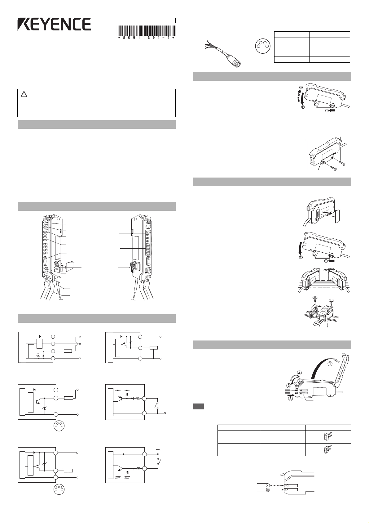
Operation status indicators
Digital monitor
Setting value
(Displayed in green)
Current value
(Displayed in red)
Dust cover
Fiber lock lever
Set button (SET)
DSC indicator
Manual button
Mode button
Power selection switch*1
Expansion protective cover
Expansion connector
Output selector
Cable*2
*1 When set to “M”, the power mode is fixed to Mega Turbo.
*2 FS-V30 does not have the cable. M8 connector for FS-V31C(P)/32C(P)
Photoelectric sensor main circuit
Max. 100mA
0 VDC
12 to 24 VDC
(Control output)
Brown *3
Blue *3
Black
Load
Overcurrent
protection circuit
0 VDC
12-24 VDC
(1)
*
(4)
Sensor main circuit
Overcurrent protection circuit
Load
(3)
*
123
4
Pin assignment
* FS-V31C only
(1)
*
(3)
*
(4)
0 VDC
12-24 VDC
Sensor main circuit
Overcurrent protection circuit
Load
* FS-V31CP only
123
4
Pin assignment
Connected pin No. Core wire cover color
(1) Brown
(2) White
(3) Blue
(4) Black
OP-73864 (cable length:2 m)
OP-73865 (cable length:10 m)
OP-73880
OP-26751 (a set of two)
96M11291
Socket Cable (Sold Separately)
For FS-V31C(P)/32C(P) Pin and wire color table
DIGITAL FIBER SENSOR
FS-V30/31(P)/31C(P)/31M/32(P)/32C(P)
Instruction Manual
Read this manual before using the product in order to achieve maximum performance.
Keep this manual in a safe place after reading it so that it can be used at any time.
• This product is just intended to detect the object(s). Do not use this product
for the purpose to protect a human body or a part of human body.
• This product is not intended for use as explosion-proof product. Do not use
this product in a hazardous location and/or potentially explosive atmosphere.
• This product is a sensor of DC power supply type. Do not apply AC power.
The product may explode or burn if an AC voltage is applied.
Precautions on Regulations and Standards
UL Certificate
This product is an UL/C-UL Listed product.
• UL File No. E301717
• Category NRKH,NRKH7
• Enclosure Type 1 (Based on UL50)
Be sure to consider the following specifications when using this product as an UL/
C-UL Listed Product.
• Use the power supply with Class 2 output defined in NFPA70 (NEC: National
Electrical Code).
• Power supply/ Control input/ Control output circuits shall be connected to a
single Class 2 source only.
• Use with the over current protection device which is rated 24V or more and not
more than 2A.
Part Names
412
3
Mounting Unit
Mounting on a DIN Rail
1
Align the claw at the bottom of the main body with
the DIN rail. While pushing the main body in the
direction of the arrow 1, slant it in the direction of
the arrow 2.
2
To dismount the sensor, raise the main body in
the direction of the arrow 3 while pushing the
main body in the direction of the arrow 1.
Installation on a Wall (Main Unit Only)
Attach the unit to the optional mounting bracket
(OP-73880), mount them together, and secure
them with two M3 screws as shown in the
illustration.
Connecting Multiple Amplifiers
Up to 16 sub units can be connected to one main unit.
1 Remove the protection cover on the side of
the main unit.
I/O Circuit
FS-V31/32/31M FS-V31P/32P
Brown *1
Monitor output
(1 to 5 V)*2
Orange
circuit
Protection
Overcurrent
protection circuit
Photoelectric sensor main circuit
Max. 100mA
Black
(Control output)
Blue *1
*1 FS-V31/31M only *2 FS-V31M only *3 FS-V31P only
FS-V31C/32C
Output Circuit Diagram Input Circuit Diagram
FS-V31CP/32CP
Output Circuit Diagram Input Circuit Diagram
12 to 24 VDC
Devices with
10 kΩ input
impedance min.
Load
0 VDC
Sensor main circuit
Sensor main circuit
DC3.3 V
(Short-circuit current
1 mA or less)
(Short-circuit
current 2 mA
or less)
2 Install the amplifier one by one on the DIN
rail.
3 Engage the two claws of the child unit with
the recesses on the main unit side until you
hear a click sound.
4 Attach the end units (option: OP-26751) to the
both ends of the connected amplifiers in the
same way as in step (2).
5 Sandwich the amplifiers between the end
units. Tighten the screws at the top (two
screws x two units) with a Phillips screwdriver
to fix the end units.
Connecting Fiber Unit
1 Open the dust cover in the direction
shown by arrow 1.
2 Move down the fiber lock lever in the
direction shown by arrow 2.
3 Insert a fiber unit into the fiber insertion
holes to a length of the fiber insertion
sign (i.e., approximately 14 mm).
(2)
PLC, etc.
*
(3)
(1)
(2)
0 VDC
12-24 VDC
*
PLC, etc.
4 Move down the fiber lock lever in the
direction shown by arrow 4.
Note
If a thin fiber unit is used, an adapter provided with the thin fiber unit will be required.
Unless the right adapter is connected, the thin fiber unit will not detect targets correctly.
(The adapter is supplied with the fiber unit.)
Cable outer dia. Adapter Appearance
φ1.3
φ1.0
•
To connect the coaxial reflective type fiber unit to the amplifier, connect the single-core
Adapter A
(OP-26500)
Adapter B
(OP-26501)
fiber to the transmitter side, and connect the multiple-core fiber to the receiver side.
Single-core fiber
Multi-core fiber
Transmitter
Receiver
1
Fiber insertion sign
Page 2
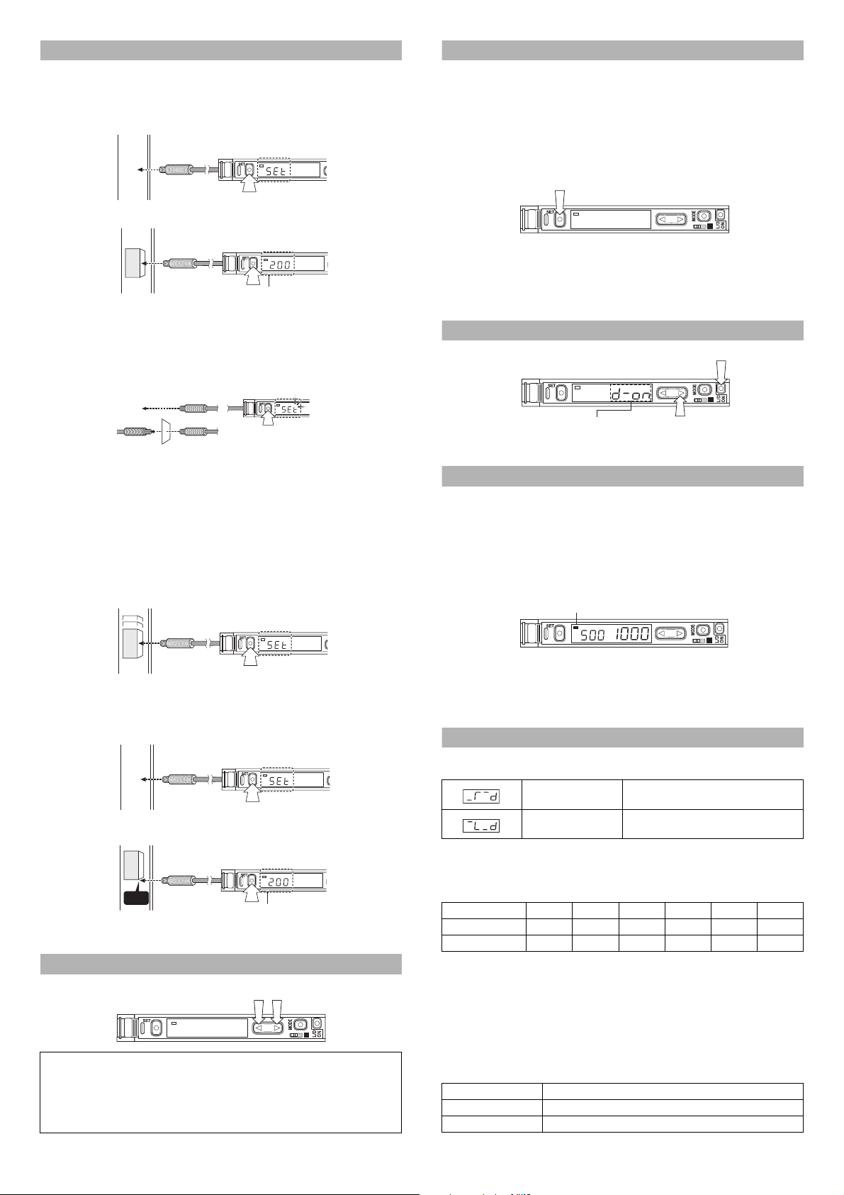
Making Sensitivity Settings
DSC
DSC
When the setting is completed,
the setting value is displayed.
Workpiece
DSC
3 sec or longer
"Reflective model"
"Through-beam model"
DSC
Workpiece
DSC
When the setting is completed,
the setting value is displayed.
Head
Workpiece
SEL
M
DSC
Two-point Calibration
In this mode, the PV used will be the mean value of two sensing values obtained
with and without a workpiece.
1
Press the SET button without any workpiece placed in front of the fiber unit.
2
Place a workpiece placed in front of the fiber unit, and press the SET button.
If the sensitivity difference does not have enough room, “
” flashes for about two seconds
after the calibration is complete. The set value is stored in memory even in that case.
Maximum Sensitivity Setting
Set the sensitivity without a workpiece in the case of the reflective type, and with a
workpiece in the case of the through-beam or retro-reflective type.
Press the SET button for three seconds in the state as shown in the above figure.
(Release the button when SET flashes.)
When setting the sensitivity, set the value slightly higher than the received light intensity.
Full Auto Calibration
In this mode, the PV will be set to the mean value of the maximum and minimum incident
values obtained within a certain period. Use this mode to detect moving workpieces.
1 Press the set button for a minimum of three seconds while the target
workpiece is passing the sensing area of the fiber unit.
• While the SET button is pressed, the sensitivity of the sensor will be set
according to the incident values.
DSC
Workpiece
• After the setting is completed, the setting value is displayed on the digital monitor.
Positioning Calibration
1 Press the SET button without any workpiece placed in front of the fiber unit.
2 Place a workpiece on the position where you want to perform positioning.
Press the SET button for 3 seconds or longer until the display flashes.
Fine-adjusting Sensitivity
The setting value can be directly changed by pressing the manual button.
DSC
When extension display (page 5, No.8) is set for the number of digits to be
displayed for the received light intensity
1
Press the manual button quickly once, and check that the setting value flashes.
2
While the setting value is flashing, change the setting value with the Manual button.
M
SEL
Percentage (%) Calibration
This is a calibration method that can set the setting value by percentage with reference to the received light intensity at the time of sensitivity setting.
For example, if the target value is set to –10P, the setting value is determined 10%
lower than the received light intensity when the SET button is pressed.
1 When selecting the sensitivity setting method (page 4, No. 2), select the %
calibration, and set the target value of calibration.
2 Taking the desired light intensity as a reference (normally without a
workpiece), press the SET button.
* While the % calibration is in use, other calibrations (sensitivity setting) cannot
be used.
* With FS-V31C(P)/32C(P), by periodically performing external calibration from
PLC or other devices, stable detection can be performed even with a small
sensitivity difference.
Output Selection
Either light-ON mode or dark-ON mode is selectable.
(1)
Press
DSC
When the area detection mode is
selected, the selection options are
NO and NC.
Dynamic Sensitivity Correction (DSC) Function
DSC automatically corrects the setting value according to the changes in the
received light intensity when there is no workpiece (output OFF).
This function is effective when the light intensity difference is small when judging
whether or not there is a workpiece.
At Detection mode selection (page 4, No.4), select “Dynamic sensitivity correction
mode” beforehand.*
How to set the sensitivity is the same as in the normal mode.
The DSC indicator illuminates when the DSC function is set.
DSC indicator
DSC
* When Light ON is selected, the upper limit of the correctable range is twice as
much as the initial setting value.
* The value is stored in memory even after the power is turned off.
*
The DSC indicator flashes when the light intensity during output OFF greatly fluctuates
or the L/D ON selection is inappropriate. In such a case, check the setting again.
Edge Detection Mode
This mode detects the change in the received light intensity during a given period
of time.
Rising edge detection Detects the increase (rising edge) of the
Falling edge detection Detects the decrease (falling edge) of the
received light intensity
received light intensity
Filter Setting
Basically, leave this setting as its initial value. If the passage interval of workpieces
is too short for the unit to respond, strengthen the level and try again.
The selectable filter level differs depending on the power modes.
Filter level HSP* FINE
Default state589999
Setting range 1 to 5 4 to 8 5 to 9 6 to 9 8 to 9 9 only
*HSP: HIGH SPEED
As the number becomes smaller, the filter becomes stronger, which makes the unit difficult to
respond to gradual changes in light intensity.
TURBO
Making Sensitivity Settings
The sensitivity is set to maximum when the SET button is pressed quickly once.
When the setting value is too low and the unit detects objects other than the workpiece, fine-adjust the setting value to a higher number.
Operation When Switching Outputs
Setting Operation
L-ON Normally OFF. Turns ON only when the light intensity changes.
D-ON Normally ON. Turns OFF only when the light intensity changes.
2
M
SEL
(2)
Press (2) within five seconds
after pressing (1).
M
SEL
SUPER ULTRA MEGA
Page 3

Area Detection Mode
HI: Upper limit
setting value
LO: Lower limit
setting value
ON
OFF
OFF
Received light
intensity
(1)pin *
(3)pin *
(2)pin
+V
0V
FS-V31C/V32C FS-V31CP/V32CP
Input OFF
Input ON
% calibration Display scaling
3 seconds
or less
Input OFF
Input ON
% calibration% calibration
3 seconds or more
Press
MODE
DSC
DSC
Press for 2 seconds
or longer.
.
.
.
.
.
Hold display selection
Select the setting by pressing the button.
Updates every time the current light
intensity is less (or more) than the
specified peak and bottom values.
Displays the maximum and minimum peak
values since the power is turned on (total
number).
Displays the maximum and minimum
bottom values since the power is turned on
(total number).
Displays the minimum peak value and the
maximum bottom value since the power is
turned on (total number).
Displays the maximum peak value and the
minimum bottom value since the power is
turned on (total number).
This mode is suited to detecting the received light intensity only of a certain range.
To set this mode, select the area detection mode at Detection mode selection (page 4, No.4).
Set the value so that the upper limit setting value is
larger than the lower limit setting value.
The unit does not respond when the upper limit setting value is less than or equal to the lower limit setting value.
Even when the above condition is satisfied, the unit
may not respond when the HI and LO values are close
to each other because of hysteresis. Be sure to operate the unit to check whether the values are valid.
How to switch the upper limit setting value (HI) and the lower
limit setting value (LO)
When the button is pressed, “HI” or “LO” and the setting value alternately flash.
When the MODE button is pressed while the display alternately flashes, the “HI” or
“LO” display changes. How to configure the sensitivity setting is the same as
when in the normal detection mode.
Setting the Display Scaling
This is the function to adjust the current received light intensity to the ìscaling target value.
1 When selecting a display value correction function (page 5, No. 6), select the
display scaling function, and set the target value.
2
During the normal display, press the SET button while pressing the MODE button.
(Scaling is performed for the current light intensity at this time.)
The reference light intensity can be set in the following range in reference with the
currently received light intensity:
Power mode Minimum value Maximum value
HIGH SPEED/FINE/TURBO
SUPER Approx. 1/40 times Approx. 8 times
ULTRA
MEGA
Approx. 1/20 times Approx. 16 times
Approx. 1/160 times
Approx. 1/320 times
Approx. 2 times
Approx. 1 time
• No value can be set when the Edge detection mode is selected.
• The value is stored in memory even after the power is turned off.
• The value is not reflected to the analog output of the FS-V31M.
• When using FS-V31C(P)/32C(P), external inputs can be used.
If the value exceeds the
range, 'TT is displayed
and scaling is performed
up to the possilbe range.
Display Selection
The factory default value is “1” only. Other items can be displayed only after being
selected at Display customization selection (page 5, No.8).
(1) (7)
DSC
Parameter Current received
(2)
Extension display
(received light intensity) *1
(3)
Bar display *2
(4)
Bar display *2 Excess gain (%) *3
DSC
DSC
DSC
light intensity
MODE
Press
MODE
Press
Current received
light intensity
MODE
Press
*1 When ULTRA/MEGA mode is selected, the current received light intensity can
be displayed up to 5 digits.
The setting value flashes when the
The setting can be changed by pressing the button while flashing.
*2 The excess gain is displayed in a 5% increment from 85 to 115%.
*3 The current light intensity for the setting value is displayed in percentage.
*4 Holds and displays the peak value and the bottom value.
How to reset the peak and bottom values (with the 5/6 display)
While pressing the MODE button, press the SET button for 3 seconds or longer to reset
the peak and bottom values. Turning the power off also resets the values.
With FS-V31C(P)/32C(P), the value can be reset externally by selecting Reset at
External input function selection (page 4, No.4-C).
User-friendly Functions (Direct Access Menu)
The hold display (5/6) can be set in detail by pressing the button for 2 seconds or longer.
Press
Press
MODE
DSC
Power mode
(6)
DSC
DSC
Excess gain (%)
Peak value
*4
(5)
MODE
DSC
DSC
Received light
intensity
Peak value *4
button is pressed once.
Current received
light intensity
MODE
Press
Excess gain (%)
Bottom value
*4
MODE
Press
Received light
intensity
Bottom value *4
Zero-shift Function
The Zero-shift function is used to forcibly set the current light intensity to zero.
1
At Display value correction function selection (page 5, No.6), select “Zero-shift function”.
2 When the SET button is pressed while the MODE button is pressed, the current
light intensity is forcibly set to zero.
• This function cannot be used when the Dynamic sensitivity correction (DSC) or
Edge detection mode is selected.
• The value is stored in memory even after the power is turned off.
• The value is not reflected to the analog output of the FS-V31M.
• When using FS-V31C(P)/32C(P), external inputs can be used.
External Input [Function only for FS-V31C(P)/V32C(P)]
1
Signals can be input externally by selecting an external input function (page 4, No. 4-C).
2
The signal can be accepted by short-circuiting the pin (2) for 2 ms or more as
shown below for each model (20 ms for OFF).
(1)pin *
(2)pin
(3)pin *
* For FS-V31C/31CP only.
• Setting using an external input is up to 1 million times.
• No inputs are accepted while setting each mode.
When external calibration is selected, the operation is the same as with the SET button.
Special Function
By performing the following operation, both sensitivity setting and scaling can be
performed using external input. Select external calibration (page 4, No. 4-C) and
display scaling. The following is the example when using the % calibration.
The power mode and attenuation function for the power mode display (3) can be
set by pressing the button for 2 seconds or longer.
DSC
Press for 2 seconds or longer.
DSC
+V
DSC
0V
Press to select (see page 4, No. 1).
MODE
Press
Press to select (see page 5, No. 5).
MODE
Press
Key Lock Function
The key lock function disables the operation of all keys.
1
While pressing the MODE button, press the ( ) button for at least three seconds.
DSC
M
SEL
The same steps can be taken to deactivate key lock.
For more information on the key lock levels and the PIN number key lock function,
refer to page 6.
3
Page 4

Operation Configuration
Basic
setting menu
1. Power mode selection
2. Sensitivity setting method selection
3. Timer mode selection
4. Detection mode selection
4-C. External input function selection
5. Light emission power selection
6. Display value correction function selection
7. Display reverse selection
8. Display customization selection
9. APC function setting
10. Power save mode setting
11. Key lock level setting
12. Interference prevention function setting
Detection
setting menu
Display
setting menu
System
setting menu
Normally, this unit can be used in the basic settings.
Set other functions as necessary.
Pressing for 3 seconds or longer displays the basic menu.
Select a function with the button, and press to confirm.
The setting for each item is confirmed when selecting END and pressing .
MODE
MODE
MODE
Detection Setting Menu
From the basic menu
DSC
MODE
Press
DSC
MODE
Press
When Timer OFF
is selected
When other
than Timer OFF
is selected
3
Timer mode selection
Select the setting by pressing the button.
Timer OFF
Off-delay
On-delay
One-shot
On-delay Off-delay *1
On-delay One-shot *1
Basic Setting Menu
Press for 3 seconds or longer
MODE
DSC
MODE
Press
DSC
MODE
Press
When Std is
selected
DSC
When SEtP
is selected
A
DSC
MODE
Press
When StG-Func
is selected
Detection
setting menu
When StG-diSP
is selected
Display
setting menu
When End is
selected
When StG-SYS
is selected
System
setting menu
End of basic menu
display
1
Power mode (response time) selection
Select the setting by pressing the button.
.
HIGH SPEED: 33 μs
.
FINE: 250 μs
.
TURBO: 500 μs
.
SUPER: 1 ms
.
ULTRA: 4 ms
.
MEGA: 16 ms
(Can be switched when the power
selection switch is set to SEL.)
2
Sensitivity setting method selection
Select the setting by pressing the button.
.
Normal sensitivity setting (see page 2)
.
Percentage(%) calibration (see page 2)
Percentage calibration target value setting
Select the setting by pressing the button.
MODE
Press
Can be set between –99 and +99%.
Menu end/continue selection
Select the setting by pressing the button.
.
.
.
.
Ends the menu.
Configures detection
settings.
(Timer, DSC, etc.)
Configures display
settings.
(Scaling, inversion, etc.)
Configures system
settings.
(APC, Power Save, etc.)
DSC
When Std or
ArEA is selected
When using
FS-V31(P)
FS-V32(P)
FS-V31M
FS-V30
DSC
When other
than SCAL
is selected
DSC
a
DSC
DSC
MODE
Press
DSC
DSC
DSC
When using
FS-V31C(P)
FS-V32C(P)
MODE
Press
DSC
Press
At Timer mode selection,
* other than 1 is selected → a
* 1 is selected → b
b
or
Press
When dSc is
selected
Press
Press
When Edge detection
is selected
Press
When SCAL
is selected
Press
Timer setting
Configure setting by pressing the button.
MODE
Can be set between 0.1 and 9999 ms.
When 1 is selected, On-delay timer is set.
Timer setting 2
Sets the time of Off-delay (One-shot).
Configure setting by pressing the button.
Can be set between 0.1 and 9999 ms.
MODE
4
Detection mode selection
Select the setting by pressing the button.
.
Normal (light intensity) detection mode
.
Dynamic sensitivity correction mode
(see page 2)
.
Area detection mode (see page 3)
.
Detects the rising edge of the received
light intensity (Edge detection mode)
(see page 2)
.
Detects the falling edge of the received
light intensity (Edge detection mode)
(see page 2)
Detection operation selection
Select the setting by pressing the button.
MODE
.
Mainly reflective type
[Light intensity with workpiece >
Light intensity without workpiece]
(The output is ON when the light
enters.)
.
Mainly transmission type
[Light intensity with workpiece <
Light intensity without workpiece]
(The output is ON when the light
is blocked.)
Correction speed selection
Select the setting by pressing the button.
MODE
1 to 3
The correction is made faster as the number
becomes larger. (Select 1 in normal cases.)
Power mode
hSP
FinE
Turb/SuPr/Ultr/MEGA
Filter time selection
Select the setting by pressing the button.
MODE
Select larger number (initial state) in normal
cases. The selectable level depends on the
power modes. (see page 2)
4-C
External input function selection
(for the connector type only)
Select the setting by pressing the button.
.
.
.
.
.
.
Display scaling target value setting
Select the setting by pressing the button.
MODE
The value can be set between 100 and 10000
in unit of 100.
10000 is displayed as .
Level 1
Level 2
114.7ms
7.34s
819.2ms
52.43s
104.86s
Does not use external input.
External calibration
Display scaling
Zero shift
Hold display reset
Light emission stop
1.64s
Level 3
1.8ms
12.8ms
25.6ms
4
Page 5

System Setting Menu
Back to A of
the basic setting.
DSC DSC
5
Light emission power selection
Select the setting by pressing the button.
Display
Power mode
FinE
Normal
Approx. 15% of the normal time
Approx. 3% of
the normal time
Turb/SuPr/
uLtr/MEGA
Approx. 1.5% of
the normal time
hSP
Approx. 11% of
the normal time
Press
MODE
Select the setting by pressing the button.
Not to be used.
Uses the display scaling function.
Uses the zero-shift function.
Display scaling target value setting
Configure setting by pressing the button.
The value can be set between 100 and
10000 in unit of 100.
10000 is displayed as FuLL.
When oFF or
ShFt is selected
When no is
selected
When SCAL
is selected
DSC
DSC
DSC
DSC
DSC
DSC
DSC
DSC
Select the setting by pressing the button.
Normal display
Reverses the display.
Even when the display is reversed,
the green light indicates setting values,
and the red light indicates received
light intensity.
Select the setting by pressing the button.
Does not customize the display.
Customizes the display.
Selectable display setting
The items shown left are displayed in
order every time the MODE button is
pressed. (see page 3)
Select the setting by pressing the
button.
Adds the item to the
selectable display.
Deletes the item from the
selectable display.
When no is
selected
Normal
Extension
Bar
Excess gain
(%)
6
Display value correction function selection
7 Display reverse selection
8 Display customization selection
(1)
(2)
(3)
(4)
Press
MODE
Press
MODE
Press
MODE
Press
MODE
.
.
.
.
.
.
.
.
.
From the basic menu
Back to A of
the basic setting.
DSC
DSC
DSC
HOLD
Power mode
HOLD
Excess gain
(%)
(5)
(7)
(6)
Press
MODE
Press
MODE
Press
MODE
When SCAL or
ShFt is selected
on page 4, No.4-C
Press
MODE
Press
MODE
Press
MODE
Press
MODE
Press
MODE
When setting each mode, the display returns normal by pressing the
button for 3 seconds or longer.
Reference
From the basic menu
DSC
MODE
Press
Display Setting Menu
MODE
DSC
Press
DSC
Press
DSC
Press
DSC
Press
Back to A of
the basic setting.
MODE
MODE
MODE
MODE
9
S-APC setting
Configure setting by pressing the button.
.
APC is enabled.
.
APC is disabled.
About APC (Auto Power Control)
In normal cases, use the sensor with APC
disabled.
When APC is enabled, the light intensity is
monitored and corrected in order to maintain
regular light transmission. If the environment is
sufficiently clean, a highly accurate detection can
constantly be performed.
Note: Long-ter m use of APC imposes heavier
load on the LED than when disabled.
10
Power save mode setting
Configure setting by pressing the button.
.
Saves power (Turns off the display).
While the power save mode is
activated, only one segment on the
digital monitor remains displayed.
.
Normal display
To turn all the displays OFF (both digital
monitor and operation status indicators)
ALL can be selected when is pressed for 3
seconds or longer while “on” is selected.
To restore the display from Display OFF, press
MODE and L/D ON buttons simultaneously for 3
seconds or longer.
11
Key lock level setting (see page 6)
Select the setting by pressing the button.
.
Level 1
.
Level 2
.
Level 3
12
Selecting the number of units of interference prevention
Select the setting by pressing the button.
.
Normal
.
The number of units of interference
prevention is twice as many as in the
normal time. (The response time is also
twice as long as in the normal time.
The detection distance is the same
as in the normal time.
Initializing, Saving and Loading the Settings
Initializing the settings
1 While pressing , press for 5 seconds or longer.
2 Select “T5V “with the button, and press .
3 Select “KPKV” with the button, and press to initialize.
Default setting
Power mode: FINE
Detection mode: Normal
Setting value: 50
Output selection: L ON
Saving the settings
1 While pressing , press for 5 seconds or longer.
2 Select “5#X'” with the button, and press .
3 Select “;'5” with the button, and press to save.
Loading the setting
1 While pressing , press for 5 seconds or longer.
2 Select “T5V” with the button, and press .
3 Select “=X5V” with the button, and press to load.
L/D
ON
L/D
ON
L/D
ON
SET
MODE
MODE
SET
MODE
MODE
SET
MODE
MODE
5
)
Page 6

Copyright (c) 2010 KEYENCE CORPORATION. All rights reserved.
11291E 1070-1 96M11291 Printed in Japan
Key Lock Level Details
Note
Power mode HIGH SPEED FINE
TURBO/SUPER/ULTRA/MEGA
Number of units
required to pre-
vent interference
0 units 4 units 8 units
Power mode HIGH SPEED FINE
TURBO/SUPER/ULTRA/MEGA
Number of units
required to pre-
vent interference
0 units 8 units 16 units
By selecting the key lock (page 5, No.11) level (1-3), key operations to be disabled can be changed.
(The default value is level 1.)
Basic Operations Button
Sensitivity
settings (p.2)
Sensitivity fineadjustment (p.2)
Power selection
(p.1)
Output
selection (p.2)
Menu selection
(p.4)
c: Normal operation is possible. °: Operation is not possible.
: The settings can be checked but cannot be changed .
SET
Power selection
switch
L/D ON
Press and hold
MODE
Level
123 123
°cc
°°°
°°°
°°
cc
Advanced Operations
Initialization
(p.3)
Display scaling
(p.3)
Zero shift (p.3)
Direct access
menu (p.3)
Display OFF/
ON (p.5, No.10)
Button
L/D ON + press
and hold SET
MODE + quickly
press SET
MODE + quickly
press SET
Press and hold
L/D.ON + press
and hold MODE
Level
°°°
°cc
°cc
°°
ccc
PIN Number Key Lock Function
The unit can be locked using a PIN number to ensure securer locking effect.
1 While pressing the MODE button, press the
DSC
()
button 10 times.
SEL
M
2 Select a PIN number between 0 and 9999 using the button.
3 Press the MODE button to activate key lock.
Follow the same step to disable the key lock. Use the same PIN number used for
locking.
Specifications
Type Main unit
NPN
output
Cable
Model
Connector
Light source Red 4-element LED (peak wave length: 640 nm typ.)
Control
output*1
Control input
(connector type only)
Response
time
Number
of interference
preven-
tion units
Power voltage 12-24 VDC, Ripple (P-P): 10% max, Class2
Power
con-
sump-
tion*3
Operat-
Incandescent lamp 20,000 lx max.
ing ambi-
ent
lumi-
nance
Operating ambient tempera-
Operating ambient humidity 35 to 85% RH (No condensation)
*1
*2
*3
ture*1
Vibration resistance
Shock resistance
Material Main unit, housing material: Polycarbonate
Weight (including cable) Approx. 80g Approx. 45g Approx. 80g Approx. 25g
When several units are connected, the operating ambient temperature varies depending on the
number of units to be connected.When connecting several units, be sure to mount the units on
the DIN rail (mounted on a metal plate), and keep the output current within 20mA.
When 1 to 2 units are connected : -10 to +55 °C,
When 3 to 10 units are connected : -10 to +50 °C,
When 11 to 16 units are connected : -10 to 45 °C
When double is set, the response time is twice as long as the normal response time.
When using the HIGH SPEED mode, the power consumption increases by 160 mW (7 mA).
PNP
output
NPN
output
PNP
output
NPN output NPN open collector 24 V 100 mA max. –
PNP output PNP open collector 24 V 100 mA max. –
Analog output
(FS-V31M only)
ON/OFF
Output
Normal time
When
double is set *2
NPN output
PNP output
Sun light 30,000 lx max.
FS-V31 FS-V32 FS-V31M FS-V30
FS-V31P FS-V32P – –
FS-V31C FS-V32C – –
FS-V31CP FS-V32CP – –
1-5 V voltage output: 1-5 V for the display 0-4095 of HSP/FINE/
TURBO, load resistance 10 k¾ or more, response time 1 ms
Calibration/scaling/zero shift/
reset/light emission stop
(input time: ON: 2 ms, OFF: 20 ms)
33 μs (HIGH SPEED)/250 μs (FINE)/
500 μs (TURBO)/1 ms (SUPER)/
Normal: 710 mW max. (Using 24 V, 29 mA max., using 12 V, 40 mA max.)
Power saving: 540 mW max. (Using 24 V, 22 mA max., using 12 V, 28 mA max.)
750 mW max. (Using 24 V, 31 mA max.,
using 12 V, 40 mA max.)/
Power saving 580 mW max. (Using 24 V,
24 mA max., using 12 V, 28 mA max.)
10 to 55 Hz Compound amplitude 1.5 mm, 2 hours for each of
Sub unit
(one line)
4 ms (ULTRA)/16 ms (MEGA)
-10 to +55 °C (No freezing)
500 m/s2 3 times for each of XYZ axes
The accessory of this unit is this instruction manual only.
Analog output
XYZ axes
(main unit)
Sub unit
(zero line)
–
193 μs to 16.7
–
ms
Write down the PIN number in case it is forgotten.
The key lock cannot be disabled unless the correct PIN number is used.
Hints On Correct Use
•
Do not wire the amplifier line along with power lines or high-tension lines, otherwise the
sensor may malfunction or receive damage due to noise.
• When using a commercially available switching regulator, ground the frame
ground terminal and ground terminal.
• Do not use the FS series outdoors, or in a place where extraneous light can
enter the light receiving surface directly.
• Due to the individual dispersion of characteristics and the difference in fiber
unit model, the maximum sensing distance or displayed value of all the units
are not the same.
• If the sensor is used in S-APC mode for a long time, the LED indicators will be
imposed with a heavy load. In that case, the sensor will be automatically set to
ACC mode where the current consumption of the sensor for light emission will
be constant, and “END APC” will be displayed. The sensor can be continuously
used in this case. Replace the sensor, however, if highly precise detection is
required.
Warranties and Disclaimers
KEYENCE, at its sole option, will refund, repair or replace at no charge any defective Products within 1 year from the date of shipment. Unless stated otherwise
herein, the Products should not be used internally in humans, for human transportation, as safety devices or fail-safe systems. EXCEPT FOR THE FOREGOING,
ALL EXPRESS, IMPLIED AND STATUTORY WARRANTIES, INCLUDING WARRANTIES OF MERCHANTABILITY, FITNESS FOR A PARTICULAR PURPOSE AND
NONINFRINGEMENT OF PROPRIETARY RIGHTS, ARE EXPRESSLY DISCLAIMED.
KEYENCE SHALL NOT BE LIABLE FOR ANY DIRECT, INDIRECT, INCIDENTAL,
CONSEQUENTIAL OR OTHER DAMAGES, EVEN IF DAMAGES RESULT FROM
THE USE OF THE PRODUCTS IN ACCORDANCE WITH ANY SUGGESTIONS OR
INFORMATION PROVIDED BY KEYENCE. In some jurisdictions, some of the foregoing warranty disclaimers or damage limitations may not apply.
Error Displays and Corrective Actions
Error display Cause Corrective action
'T=
'TG
'PF#2=
Overcurrent is flowing in the control
Failed to write/read the internal data. Perform initialization (p.5).
The load on the light source is large.
output.
Check the load and return the current
within the rated value.
Replace the sensor if high-accuracy
detection is required.
6
 Loading...