

Page 1
WARNING
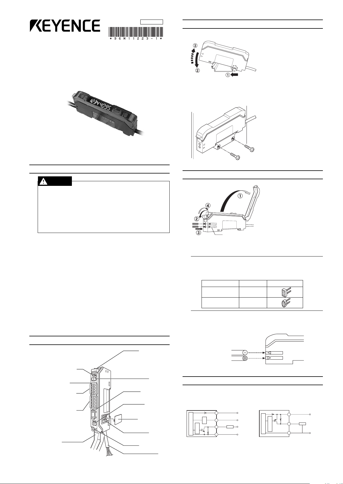
Operation indicator*
Digital monitor
Preset value (PV)
green indicator
Current value (CV)
red indicator
Dust cover
Fiber lock lever
Set button
Manual button
Mode button
Expansion
protective cover
Expansion
connector
Output selector
Cable
96M11223
Fiber insertion sign
Cable outer dia.
ø1.3
ø1.0
Adapter
Adapter A
(OP-26500)
Adapter B
(OP-26501)
Appearance
Single-core fiber
Multi-core fiber
Transmitter
Receiver
Monitor output (1 to 5 V)*
Max. 100mA
0 V
12 to 24 VDC
Devices with 10 kΩ
input impedance min.
(Control output)
Blue
Black
Orange*
Load
5 to 40 VDC
Brown
Photoelectric
sensor main circuit
Overcurrent
protection circuit
Protection
circuit
* FS-V21RM only.
Max. 100mA
0 VDC
12 to 24 VDC
(Control output)
Brown
Blue
Black
Load
Photoelectric
sensor main circuit
Overcurrent
protection circuit
3. Mounting Unit
Dual Digital Fiber Sensor
FS-V21/21G/21R(P)/21RM/21X
Instruction Manual
Read this manual before using the product in order to achieve
maximum performance.
Keep this manual in a safe place after reading it so that it can be
used at any time.
1. Safety Precautions
• This product is just intended to detect the object(s). Do not use this
product for the purpose to protect a human body or a part of human
body.
• This product is not intended for use as explosion-proof product. Do
not use this product in a hazardous location and/or potentially
explosive atmosphere.
• This product uses DC power. Do not apply AC power. The product
may explode or burn if an AC voltage is applied.
■ UL Certificate
This product is an UL/C-UL Listed product.
• UL File No. E301717
• Category NRKH, NRKH7
• Enclosure Type 1 (Based on UL50)
Be sure to consider the following specifications when using this product
as an UL/C-UL Listed Product.
• Use the power supply with Class 2 output defined in NFPA70 (NEC:
National Electrical Code).
• Use with the over current protection device which is rated 30V or more
(rated 40V or more for NPN output type) and not more than 2A.
● DIN Track Mounting
1) As shown in the illustration, engage
the claw on the lower side of the
unit and the DIN rail, press the unit
in the direction shown by arrow ➀,
and move down the unit in the direction shown by arrow ➁.
2) When dismounting the unit, press
the unit in the direction shown by
arrow ➀ and move up the unit in
the direction shown by arrow ➂.
● Using Mounting Bracket (accessory)
• Attach the unit to the mounting
bracket, mount them together, and
secure them with two M3 screws
as shown in the illustration.
4. Connecting Fiber Unit
1) Open the dust cover in the direction shown by arrow ➀.
2) Move down the fiber lock lever
in the direction shown by arrow
➁.
3) Insert a fiber unit into the fiber
insertion holes to a length of the
fiber insertion sign (i.e., approximately 14 mm).
4) Move up and return the fiber
lock lever in the direction shown
by the arrow ➃.
Note:If a thin fiber unit is used, an adapter provided with the thin fiber unit
will be required.
Unless the right adapter is connected, the thin fiber unit will not
detect targets correctly.
2. Part Names
■ Accessories
Check that all the accessories are ready before use.
Instruction manual (x 1) Mounting bracket (x 1)
* The operation indicator of the FS-V21X (infrared model) will not be lit.
•To connect the coaxial reflective type fiber unit to the amplifier, connect
the single-core fiber to the transmitter side, and connect the multiplecore fiber to the receiver side.
5. I/O Cricuit
Refer to the following I/O circuit diagram when connecting the unit to peripheral devices.
● FS-V21/21G/21R/21RM/21X ● FS-V21RP
1
Page 2
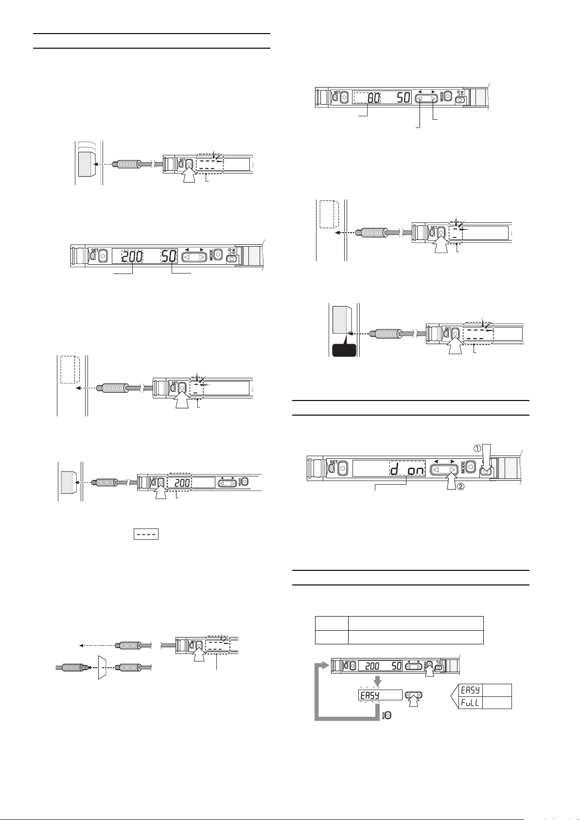
PV
The PV value decreases by pressing
this side of the manual button.
The PV value increases
by pressing this side of
the manual button.
Workpiece
The display will be lit
when the workpiece
is detected.
3 s min.
Workpiece
The display will flash
for a moment when
the setting is
finished. Then the
PV will be displayed.
Front edge
Press the output selector.
The display indicates that
the sensor is in dark-ON
mode. The CV will be
displayed if no buttons are
operated for approximately
five seconds.
Press the manual button
➁
within five seconds after
pressing the output
selector ➀.
EASY Only basic functions are displayed.
FULL All available functions are displayed.
EASY
FULL
Press 3 s min.
Press 3 s min.
Completion
of selection
Select
6. Making Sensitivity Settings
3 s min.
Workpiece
The display will
flash when the
settings are
completed.
PV (green)
CV (red)
Workpiece
The display will be lit
when the workpiece
is detected.
Workpiece
The PV will appear when
the settings are completed.
3 s min.
The display will flash
for a moment when
the setting is finished.
Then the PV will be
displayed.
“Reflective model”
“Through-beam model”
● Full Auto Calibration
In this mode, the PV will be set to the mean value of the maximum and
minimum incident values obtained within a certain period.
Use this mode to detect moving workpieces.
1) Press the set button for a minimum of three seconds while the target
workpiece is passing the sensing area of the fiber unit.
• While the set button is pressed, the sensitivity of the sensor will
be set according to the incident values.
• When the setting is finished, the digital monitor will display the PV
in green.
● Two-point Calibration
In this mode, the PV used will be the mean value of two sensing values
obtained with and without a workpiece.
1) Press the set button for a moment without the workpiece in the sensing area (i.e., in front of the fiber unit).
● Manual Calibration
In this mode, make manual PV settings.
● Positioning Calibration
In this mode, a workpiece will be detected when the front edge of the
workpiece has reached a preset position.
1) Press the set button for a moment without the workpiece in the sensing area (i.e., in front of the fiber unit).
2) Locate the front edge of the workpiece in the sensing area. Then
press the set button for a minimum of three seconds.
2) Locate the workpiece in the sensing area (i.e., in front of the fiber unit).
Then press the set button for a moment.
* If there is extremely little difference in sensitivity between the sens-
ing values, the display will flash on completion of tuning.
● Maximum Sensitivity Setting
If the sensing performance of the sensor drops due to dust or dirt, set
the sensitivity of the sensor to maximum.
1) Press the set button without a workpiece if the fiber unit is a reflec-
tive model. Press the set button with a workpiece if the fiber unit is a
through-beam model. In both cases, press the set button for a minimum of three seconds.
7. Selecting Output
Either light-ON mode or dark-ON mode is selectable.
•Take the same steps to set the sensor to light-ON mode again.
8. User-friendly Functions
● Access Mode Selection
Two modes are available to the display of values and menu items.
* If the sensing distance is insufficient, make sensitivity settings in the
sensor in two-point tuning mode.
• The mode is set to EASY before shipping.
2
Page 3

Excess
gain
Output
status
Power
mode status
PV CV
Press
Press
CV
Press
•The CV is displayed in
percent based on the
PV.
•
The current value will be
displayed if no keys are operated
for approximately 30 s.
•
If the timer function is set, the
output status with power mode
and the timer mode with set time
will be displayed alternately.
Press
Press
CV
Peak value Bottom value
LED bar
indicator
Output
status
Peak
excess
gain
Bottom
excess
gain
Power
mode status
Press
Press
Press
Press
Excess
gain
PV CV
CV
Access mode
selection
Power mode
selection
Timer function
setting
Press
Press manual
button to select
Press manual
button to select
Press the
mode button 3 s min
Press
Other than
FINE
TURBO
SUPER
TURBO
Press
Press
Press to manual button to
make timer adjustments
* For timer values, refer to the
corresponding table under FULL
mode.
Normal
operation use
Timer OFF
(for
normal operation use)
OFF-delay timer
ON-delay timer
One-shot timer
Used if the sensing
distance is insufficient
while the sensor is in
fine mode.
Used if the sensing
environment is bad
due to dust or other
obstacles.
Press the
mode button 3 s min
Access
mode
selection
Power
mode
selection
Select
Select
Select
Select
Edge
detection
mode
selection
Select
Select
S-APC
mode
setting
FINE
TURBO
SUPER TURBO
ULTRA TURBO
HIGH SPEED
HIGH RESOLUTION
Timer
function
setting
Power save
function
setting
Shift
function
setting
Press
Press
Press
Used to detect sensing objects highly
precisely under clean environments.
OFF (for normal operation use)
Rising edge
Falling edge
OFF (for normal operation use)
ECO half
ECO all
OFF (for normal operation use)
Shift ON
OFF (for normal operation use)
Press
Timer adjustments
* A maximum error of ±10% of the PV.
Timer adjustment range
Press
Press
Press
Press
Press
Shift value CV
Shift value adjustment
1~30ms
30~50ms
50~200ms
200~500ms
1-ms increments
2-ms increments
10-ms increments
50-ms increments
Power mode
,
Other than
Power mode
,
Other than
Power mode
Power mode
Other than
Normal operation use
Used if the incident is insufficient while
the sensor is in SUPER TURBO mode.
Used to detect sensing objects
moving at high speed.
Used to detect delicate differences
within a short sensing distance.
Timer OFF (for normal operation use)
OFF-delay timer
ON-delay timer
One-shot timer
Used if the sensing distance is insufficient
while the sensor is in fine mode.
Used if the sensing environment is
bad due to dust or other obstacles.
● Display Selection (Access Mode: EASY)
● Display Selection (Access Mode: FULL)
● Menu Selection (Access Mode: EASY)
● Menu Selection (Access Mode: FULL)
Note:•Press the mode button ( ) for a minimum of three seconds to return to the display of the CV from any menu selection stage. To return to the
previous display, press the mode button (
• When the power mode is set to HIGH RESOLUTION, the S-APC mode will be always turned ON.
• When the power mode is set to HIGH SPEED, the S-APC mode will be always turned ON in the case of the R model, or otherwise the S-APC mode
will be always turned OFF.
Sensitivity Settings in Edge Detection Mode
The sensitivity of the sensor will be set to maximum by pressing the
while the sensor is in edge detection mode. Make fine sensitivity adjustments by pressing the
) first, and press the left side ( ) of the manual button ( ).
.
3
Page 4

9. Key Lock
Indicates that the
keys are locked.
Press the manual button for
three seconds while pressing
the mode button.
EASY
FINE
OFF
Light-ON
Access mode
Power mode
Timer function
Output selection
y
)
Normal
ECO half
ECO all
Normal
ECO half
ECO all
Model
Other than
R model
R model
Preset value/Current value display
Output selection (Dark ON)
Output selection (Light-ON)
Access mode selection (EASY)
Access mode selection (FULL)
Excess gain display
LED bar display
Hold display
Power mode selection (FINE)
Power mode selection (TURBO)
Power mode selection (SUPER TURBO)
Power mode selection (ULTRA TURBO)
Power mode selection (HIGH SPEED)
Power mode selection (HIGH RESOLUTION)
Timer function setting (Timer OFF)
Timer function setting (OFF-delay timer)
Timer function setting (ON-delay timer)
Timer function setting (One-shot timer)
S-APC mode setting (S-APC OFF)
S-APC mode setting (S-APC ON)
Edge detection mode (OFF)
Edge detection mode (Rising edge)
Edge detection mode (Falling edge)
ECO mode setting (ECO mode OFF)
ECO mode setting (ECO half)
ECO mode setting (ECO all)
Shift function setting (Shift OFF)
Shift function setting (Shift ON)
Key lock setting
Key unlock
Forecast maintenance warning (END APC)
The key lock function disables the operation of all keys.
•Take the same step to unlock the keys.
10. Mode Settings before Shipping (Initialization)
The following factory settings are made before shipping.
* Returning to factory settings: Press the button for a minimum of
five seconds while pressing the button.
11. Hints On Correct Use
•To extend the cable length, use a cable with at least a 0.3 mm2 crosssection area. Limit the length of cable extension to no more than 100 m.
(To connect several units, contact Keyence for further information.)
• Do not wire the amplifier line along with power lines or high-tension lines,
or otherwise the sensor may malfunction or receive damage due to noise.
• When using a commercially available switching regulator, ground the
frame ground terminal and ground terminal.
• Do not use the FS series outdoors, or in a place where extraneous light
can enter the light receiving surface directly.
• Due to the individual dispersion of characteristics and the difference in
fiber unit model, the maximum sensing distance or displayed value of
all the units are not the same.
• If the sensor is used in S-APC mode for a long time, the LED indicators
will be imposed with a heavy load. In that case, the sensor will be automatically set to ACC mode where the current consumption of the sensor for light emission will be constant, and “END APC” will be displayed.
The sensor can be continuously used in this case. Replace the sensor,
however, if highly precise detection is required.
12. Specifications
Model
Light source
Response time
Display shift function
Timer function
Control output
Monitor output
Supply voltage
Current consumption
Rating
Ambient illumination
Ambient temperature
Relative humidity
Vibration
Shock resistance
Environment resistance
Housing material
Size
Weight
*3
*1. The model is sold only in Japan. Consult your KEYENCE representa-
tive if the model is required outside Japan.
*2. The maximum current will be 20 mA in the case of expansion.
*3. Only the FS-V21RM has monitor output.
Set the Unit to FINE or TURBO mode to use monitor output.
FS-V21*1FS-V21G
Red LED Greed LED
250µs (FINE)/500µs (TURBO)/1ms (SUPER TURBO)/
4ms (ULTRA TURBO)/500µs (HIGH RESOLUTION)/
50µs (HIGH SPEED)
Max. ±1999 (variable)
Timer OFF, OFF-delay timer, ON-delay timer, and oneshot timer (1 to 500 ms)
NPN open collector output at 40 V (or PNP open
collector output at 30 V) with 100 mA max.
residual voltage of 1 V max.
Voltage output at 1 to 5 V (1 to 5 V for a FINE or
TURBO display range between 0 and 4095)
Load resistance: 10 kΩ min.
Repetitive accuracy: ±0.5% of FS
DC12-24V ±10% with a maximum ripple (peak to peak)
of 10%, Class 2
Incandescent lamp: 20,000 lux max.
Sunlight: 30,000 lux max.
-10°C to 55°C (No freezing)
35% to 85% RH (No condensation)
10 to 55 Hz, 1.5-mm double amplitude,
each in X, Y, and Z directions for two hours
2
Three times each in X, Y, and Z directions
500 m/s
Unit and cover are both polycarbonate made
W 9 mm x L70 mm x H 30 mm
Approximatel
FS-V21R (P)
4-element red LED 4-element red LED
S-APC
Mode
80 g (including 2-m cable
S-APC mode turned ON or when
mode OFF
the HIGH SPEED mode is selected.
580 mW
480 mW
430 mW
650 mW
530 mW
480 mW
FS-V21RM*1FS-V21X
Infrared (950 nm)
*2
and a
720 mW
600 mW
550 mW
720 mW
600 mW
550 mW
13. List of Digital Display Items
WARRANTIES (MUST ACCOMPANY THE PRODUCTS): KEYENCE, at its sole
option, will refund, repair or replace at no charge any defective Products within
1year from the date of shipment. Unless stated otherwise herein, the Products
should not be used internally in humans, for human transportation, as safety
devices or fail-safe systems. EXCEPT FOR THE FOREGOING, ALL EXPRESS,
IMPLIED, AND STATUTORY WARRANTIES, INCLUDING WARRANTIES OF
MERCHANTABILITY, FITNESS FOR A PARTICULAR PURPOSE AND NON-INFRINGEMENT OF PROPRIETARY RIGHTS, ARE EXPRESSLY DISCLAIMED.
*1
KEYENCE SHALL NOT BE LIABLE FOR ANY DIRECT, INDIRECT, INCIDENTAL,
CONSEQUENTIAL OR OTHER DAMAGES, EVEN IF DAMAGES RESULT FROM
THE USE OF THE PRODUCTS IN ACCORDANCE WITH ANY SUGGESTIONS OR
INFORMATION PROVIDED BY KEYENCE. In some jurisdictions, some of the
foregoing warranty disclaimers or damage limitations may not apply.
4
 Loading...