

Page 1
Instruction
Manual
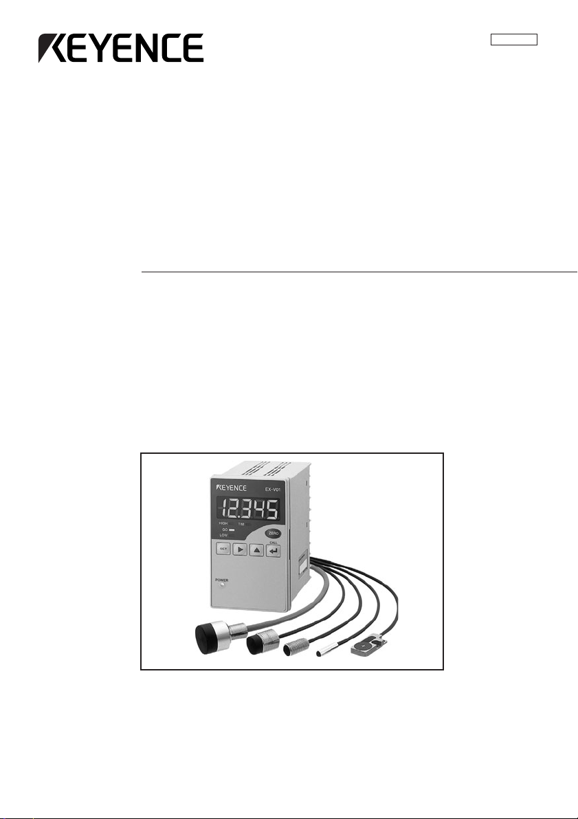
High-speed, High-Accuracy
Digital Displacement Sensor
EX-V Series
96M0558
Page 2

Safety Precautions
Symbols
This instruction manual describes the operation and function of the EX-V. Read this
manual carefully to ensure safe use and maximum performance from your EX-V.
The following symbols alert you to important messages. Be sure to read these
messages carefully.
WARNING
Failure to follow instructions may lead to injury. (electric
shock, burn, etc.)
General precautions
CAUTION
Note:
• At startup and during operation, be sure to monitor the functions and performance of the EX-V.
• We recommend that you take substantial safety measures to avoid any damage
in the event a problem occurs.
• Do not open or modify the EX-V or use it in any way other than described in the
specifications.
• When the EX-V is used in combination with other instruments, functions and
performance may be degraded, depending on operating conditions and the
surrounding environment.
• Do not use the EX-V for the purpose of protecting the human body.
Failure to follow instructions may lead to product damage.
Provides additional information on proper operation.
i
Page 3
Warning and cautions specific to the EX-V Series
Operating environment
For optimum performance of the EX-V, always maintain a proper operating environment.
CAUTION
Connecting the EX-V to analog input equipment
To prevent malfunction, do not install the EX-V in the following places:
• Places directly exposed to sunlight.
• Places where the ambient temperature drops below 0
• Places where the relative humidity drops below 35% or exceeds 85%.
• Places where temperature fluctuations may cause condensation.
• Places where the EX-V may be exposed to corrosive or flammable gas.
• Places exposed to airborne dust or corrosive substances such as salt or
metal particles.
• Places where the EX-V may be subjected to vibration or impact.
• Places where water, oil or chemicals may splash the EX-V .
• Places where the EX-V may be affected by noise interference.
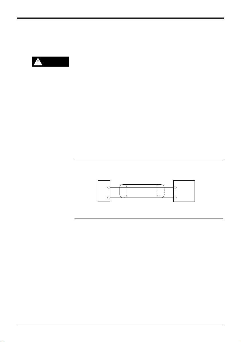
Take the following countermeasures to prevent the EX-V from malfunctioning due
to noise interference.
Note 1: Use a 1-core shielded cable for the output line. When using an analog
voltage signal, do not use a cable longer than 10 m. If the cable needs to be
longer than 10 m, convert the voltage signal into a current signal.
1-core shielded cable
EX-V
Analog
voltage
output
0 V
Note 2: Keep the wiring and connection cables separate.
Note 3: Isolate the wiring and connection cables from high-voltage or power lines;
otherwise noise may cause the EX-V to malfunction.
°
C or exceeds 50°C.
Various types of
Input
0V
display equipment
96M0558
ii
Page 4

MEMO
iii
Page 5
How this manual is organized
Chapter 1 Preparation
Describes the package contents, and explains the mounting and adjusting procedures of the controller and sensor head.
Chapter 2 Quick Guide to Basic Mode Operation
Explains the kinds of the measurement modes and the selection procedure.
Selecting the mode best suited to your detection purpose allows you to quickly
operate the sensor by easy setting.
Chapter 3 Use of Common Functions
Explains the functions common to the respective modes and the setting
procedure.
Chapter 4 Use of Data Processing Functions
Explains the setting and operation procedures of the respective functions.
Chapter 5 Troubleshooting
Explains the error messages displayed when an error has occurred, and
countermeasures to be taken.
Chapter 6 Specifications and Dimensions
Read as necessary.
Index
Read as necessary.
Warranties
iv
Page 6

Contents
Chapter 1 Preparation
1.1 Checking the Package Contents .......................................................... 2
1.2 Part Names and Functions .................................................................... 3
1.3 Terminal Names and Connections .......................................................4
1.4 Input/output Circuits .............................................................................. 5
1.5 Mounting ................................................................................................. 6
1.5.1 Mounting and dismounting the controller .................................................. 6
1.5.2 Mounting the sensor head ........................................................................ 7
1.6 Adjustment ............................................................................................. 9
1.6.1 Connection ................................................................................................9
1.6.2 Adjusting the output characteristics .......................................................... 9
Chapter 2 Quick Guide to Basic Mode Operation
2.1 Measurement Modes ........................................................................... 12
2.1.1 Bottom-dead-center mode ...................................................................... 12
2.1.2 Eccentricity/vibration mode ..................................................................... 12
2.1.3 Thickness/gap mode ...............................................................................13
2.1.4 Manual mode .......................................................................................... 13
2.2 Quick Guide to Basic Mode Operation .............................................. 14
2.2.1 Setting the bottom-dead-center mode .................................................... 14
2.2.2 Setting the eccentricity/vibration mode ................................................... 18
2.2.3 Setting the thickness/gap mode ..............................................................21
2.3 Auto-Zero Function .............................................................................. 24
2.4 Tolerance Limit Value Setting ............................................................. 25
2.5 Checking the Tolerance Limit Values
(Calling the tolerance limit values) ..................................................... 27
Chapter 3 Use of Common Functions
3.1 Table of Functions and Function Numbers ....................................... 30
3.2 Function Setting Flow ......................................................................... 31
3.2.1 Selecting the function using the
3.2.2 Display scaling function [E] ..................................................................... 33
3.2.3 Monitor (analog voltage) output setting function [F] ................................ 36
3.2.4 Digits function/decimal point function [g] ................................................. 39
3.2.5 Offset function [x] ....................................................................................40
3.2.6 Output form selection function [I] ........................................................... 42
3.2.7 Panel-lock function [j] ............................................................................. 43
v
key .................................................. 31
Page 7

Chapter 4 Use of Data Processing Functions
4.1 Table of Data Processing Functions .................................................. 46
4.2 Details of Bottom-dead-center Mode ................................................. 47
4.2.1 No. of averaging measurements/Digital filter [A] ..................................... 47
4.2.2 Measurement type [b] ............................................................................. 49
4.2.3 Measurement period [[] .......................................................................... 53
4.2.4 Previous value comparison function [d] .................................................. 56
4.3 Details of Eccentricity/vibration Mode .............................................. 57
4.3.1 No. of averaging measurements/Digital filter [A] ..................................... 57
4.3.2 Measurement type [b] ............................................................................. 57
4.3.3 Measurement period [[] .......................................................................... 61
4.4 Details of Thickness/gap Mode ......................................................... 64
4.4.1 No. of averaging measurements/Digital filter [A] ..................................... 64
4.4.2 Measurement type [b] ............................................................................. 64
4.4.3 Measurement period [[] .......................................................................... 69
4.4.4 Inverse/normal display function [d] ......................................................... 73
4.5 Details of Manual Mode .......................................................................74
4.5.1 No. of averaging measurements/Digital filter [A] ..................................... 74
4.5.2 Measurement type [b] ............................................................................. 74
4.5.3 Measurement period [[] .......................................................................... 84
4.5.4 Previous value comparison function [d] .................................................. 84
4.6 Hysteresis Setting ................................................................................ 85
4.7 Initialization .......................................................................................... 86
Chapter 5 Troubleshooting
5.1 Error Messages ....................................................................................88
5.2 Troubleshooting List ........................................................................... 89
Chapter 6 Specifications and Dimensions
6.1 Specifications ....................................................................................... 92
6.2 Characteristics Charts ......................................................................... 93
6.3 Minimum Input Time and Output Response Time ............................ 96
6.4 Dimensions ........................................................................................... 98
Index
Index .............................................................................................................. 101
Warranties
WARRANTIES AND DISCLAIMERS ............................................................ 109
vi
Page 8

Quick Index by Function/Operation
This index helps you quickly find proper EX-V function/operation according to your
purpose.
Select action or operation you need to find the proper page and description.
Display/Setup
noitarepO/noitcnuFnoitpircseDegaP
tfirderutarepmet
ecived
noitcnufhcae
sliateddna
stluafed
tnemtsujda
reggirt
dohtem
eulav
langistuptuo
ecivedlanretxemorf
stigid
"0"oteulav
tnemtsujda
yrotcafotsgnittesllagnizilaitinI
noitarepolenaptnorfgnikcoLnoitcnufkcol-lenaP34
eulavyalpsidmorf/ot
tuptuoegatlovrotinomgnitteS
eulavyalpsidmorftnednepedni
GN/KOrofseulavecnarelotgniweiVseulavtimilecnarelotehtgnillaC72
GN/KOrofseulavecnarelotgnitteSgnitteSeulaVtimiLecnareloT
ropu-tratstanoitautculfgnirongI
lanretxemorflangisgnimitgnittupnI
fossecorpputesfoeniltuogniweiV
srebmunnoitcnufllafotsilgniweiV
gniruddoireptnemerusaemgnikcehC
srosnesgnimittuohtiwgnireggirTreggirtlanretnI35
tinuegnahcottnioplamicedgnivoMnoitcnuftnioplamiceD93
lanretnirofemitgnirusaemgnignahC
gnigarevatnemerusaemgnidiceD
lortnoc/tupniehtotgnidroccaemit
gniveihcarofeulavtesffo/niaggnitteS
tupnitsniagaeulavyalpsidderised
rotarapmocrofremityaled-ffognitteS
langistuptuorotarapmocgnidloHtuptuodloH24
eulavecnarelotrotarapmocgnitceleS
4ottigideulavyalpsidgnignahC
eulavderisedgnitcartbus/gniddA
yalpsid)gnitteser(gnignahcylkciuQ
gnirudtuptuorotarapmocgnilbasiD
retnec-daed-mottobenihcamsserp
tupnignimiT4
yek]TES[gnisunoitcnuf
srebmuN
noitazilaitinI68
tuptuoebortS4
yaledgnilpmaS35
noitcnuf
tuptuoyaled-ffO24
tupnignitteslanretxE21
noitcnufstigiD93
noitcnuftesffO04
noitcnuForeZ-otuA42
tupnielbasidtuptuO41
noitcnuf
noitcnufnosirapmoceulavsuoiverP65
hcaerofssecorpputesfoeniltuO
noitcnuFdnasnoitcnuFfoelbaT
stnemerusaemgnigarevafo.oN84
gnittestuptuo)egatlovgolana(rotinoM
gnittestuptuo)egatlovgolana(rotinoM
52
64
64,03
63
63
vii
Page 9
Measurement
Installation
noitarepO/noitcnuF
ssenkcihtgnirusaeM
rettamngierof
noitrop
noitisop
oteuderuliaferusolceidgnikcehC
eliforpwolfothgiehgnirusaeM
nigirofotnemecalpsidgnirusaeM
htiwgnimrofnieruliafgnitceteD
enihcamgnidlomnoitcejni
rorregnikcuhcgnitceteD
etalpesabfonoitarbivgnirusaeM
lootgnittucfotuonurgnirusaeM
ecnarelotrotarapmocgnittupnI 52
rellorfoyticirtneccegnirusaeM
.erusolc
noitpircseD
edompag/ssenkcihtehtgnitteS.1
timilecnarelotehtgnitteS.2
niedomtnemerusaemehtgnitteS.1
.)edomlamroN(gnitteslaitini
timilecnarelotehtgnitteS.2
otepyttnemerusaemehtgnitteS.1
timilecnarelotehtgnitteS.2
niedomtnemerusaemehtgnitteS.1
.)edomlamroN(gnitteslaitini
timilecnarelotehtgnitteS.2
\otepyttnemerusaemehtgnitteS.1
otretnec-daed-mottobdetimiL
gnirudecnaraelcdlomehterusaem
timilecnarelotehtgnitteS.2
timilecnarelotehtgnitteS.2
timilecnarelotehtgnitteS.2
timilecnarelotehtgnitteS.2
timilecnarelotehtgnitteS.2
egaP
.putesforedroehtetacidni.2dna.1srebmuN
12
67
.edompaG/ssenkcihTnitnettimretnI
12
67
41
edomnoitarbiv/yticirtnecceehtgnitteS.1
81
edomnoitarbiv/yticirtnecceehtgnitteS.1
81
edomnoitarbiv/yticirtnecceehtgnitteS.1
81
edomnoitarbiv/yticirtnecceehtgnitteS.1
81
noitarepO/noitcnuFnoitpircseDegaP
lairetamlatemotnirosnesgniddebmEtnuom-hsulF
noitisop
elbacrosnesgnidnetxE.dnetxetonoD8
elbacrosnesgnittuC.tuctonoD8
esolcnisrosneselpitlumgnillatsnI
ecnerefretnilautuM8
7
viii
Page 10

ix
Page 11

Chapter 1
Preparation
Describes the package contents, and explains the mounting and adjusting
procedures of the controller and sensor head.
1.1 Checking the Package Contents ......................................... 2
1.2 Part Names and Functions .................................................. 3
1.3 Terminal Names and Connections ......................................4
1.4 Input/output Circuits ............................................................ 5
1.5 Mounting ................................................................................ 6
1.5.1 Mounting and dismounting the controller ................................. 6
1.5.2 Mounting the sensor head ....................................................... 7
1.6 Adjustment ............................................................................ 9
1.6.1 Connection............................................................................... 9
1.6.2 Adjusting the output characteristics .........................................9
Page 12
Chapter 1 Preparation
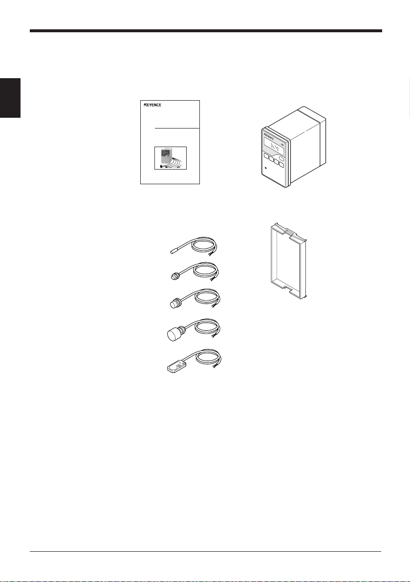
1.1 Checking the Package Contents
The EX-V series package includes the following parts and equipment. Check that
all the parts and equipment are included in the package.
1
• Instruction manual: 1 • Controller: 1
Instruction
Manual
High-speed, High-Accuracy
Digital Displacement Sensor
EX-V Series
• Sensor head: • Panel mounting frame: 1
Ordered one of the following
EX-305V
EX-110V
EX-416V
EX-422V
EX-614V
2
Page 13
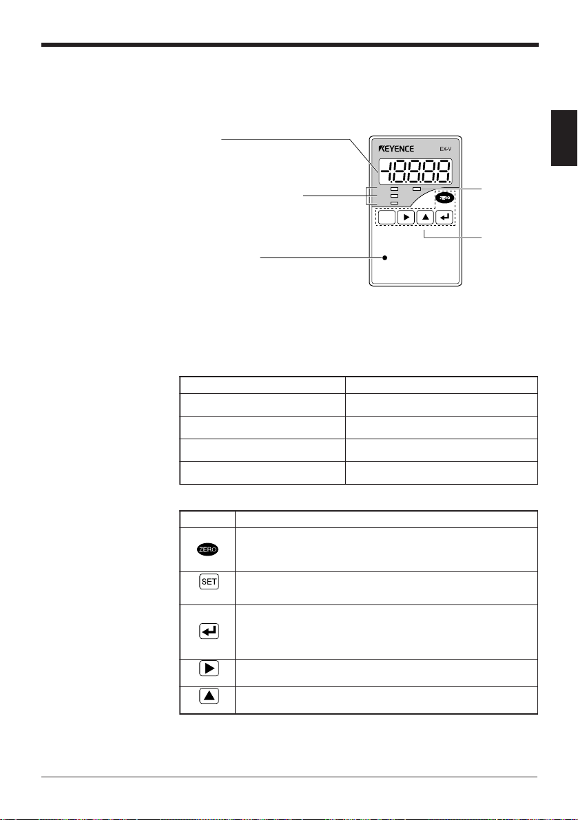
1.2 Part Names and Functions
This section explains the part names and functions.
■ Controller
Display
Displays the measured value. The value is
displayed in green when the measured value is
within the tolerance range. The value is displayed
in red when the measured value is out of the
tolerance range.
Comparator output indicators
Illuminates when the comparator output
(HIGH, GO, LOW) is turned on.
Indicates the type of displayed tolerance limit
value when setting or calling the tolerance
limit value.
POWER indicator
Illuminates green:
When operation is normally performed
Illuminates red:
When the control output is reset to OFF
■ Displays and functions
yalpsiDnoitcnuF
)999.91±(eulavciremuN
)V8.5+:tuptuo
)V8.5-:tuptuo
Chapter 1 Preparation
1
TIMING input
.egnaryalpsidehtwolebsi
indicator
Illuminates
when a timing
signal is input.
Operation
keys
.deyalpsidebottlusernoitarepoonsierehT
ciremunasadeyalpsidsitlusernoitarepoehT
sitlusernoitarepoehtnehwdeyalpsidsi"FFFF"
tlusernoitarepoehtnehwdeyalpsidsi"FFFF-"
HIGH TIM
GO
LOW
POWER
SET
FUNC
UTILITY
MODE
CALL
CALIB
.eulav
egatlovgolanA,NO:tuptuoHGIH(FFFF
.egnaryalpsidehtevoba
egatlovgolanA,NO:tuptuoWOL(FFFF-
)V0:tuptuoegatlovgolanA
,FFO:stuptuoWOLdnaOG,IH(----
■ Operation keys
yeKnoitcnuF
➮
(.eulav
FUNC
CALL
CALIB
UTILITY
MODE
(
➮
(.noitcnuf
➮
.)orez("0000"otyalpsidehtnoeulavehtsteseR•
.04egapees,sliatedroF
)
➮
(.edomgnittestimilecnarelotehtsllaC•
.edomtnemtsujdaehtsllaC•
.gnitteshcaesevaS•
.egassemrorrehcaeslecnaC•
.72egapees,sliatedroF
)
.gnitteshcaestceleS•
.rebmunnoitcnufhcaesteS•
.edomtnemerusaemehtsllaC•
.gnittesnoitcnufgnirudsgnittesnoitcnufllasezilaitinI•
.47dna,46,75,84segapees,sliatedroF
)
.tnemerusaemgnirudeulavtimilecnarelotehtsllaC•
.)"J"ot"E"(sedomnoitcelesnoitcnufnommocehtsllaC•
tesffoehtottesersiyalpsidnoeulaveht,detcelessinoitcnuftesffoehtfI
.52egapees,sliatedroF
)
hcaefognittesmrofrepot)"D"ot"A"(sedomgnittesnoitcnufehtsllaC•
3
Page 14
Chapter 1 Preparation
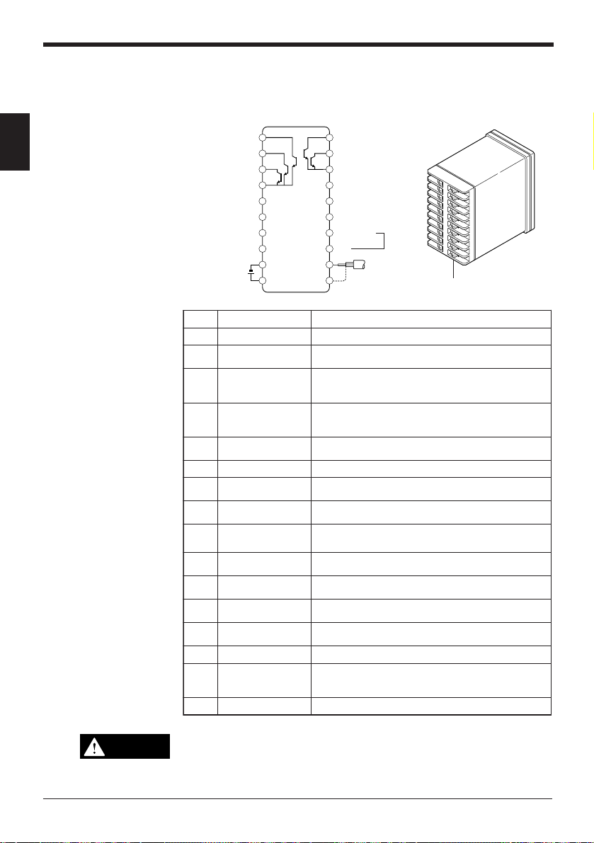
1.3 Terminal Names and Connections
This section explains the terminal names and functions.
10
1
OUTPUT DISABLE
HIGH
GO
LOW
GND1
TIMING
HOLD RESET
ZERO
24V DC
9
8
7
6
5
4
3
–
2
+
1
20
ALARM
19
STROBE
18
GND2
17
EXT1
16
EXT2
15
SYNC
14
MONITOR
13
0V
12
11
Sensor head
Terminal block
.oNemanlanimreTnoitcnuF
2,1ylppusrewoP %01±CDV42
3
4tupniorez-otuA
5tupniteser-dloH
6tupnignimiT
tuptuorotarapmoC
tupnielbasid
.lanimretgnidnuorgehtotdetiucric-trohs
.lanimretgnidnuorgehtotdetiucric-trohs
.atadedomdlohhcaesteseR.2.tuptuo
.lanimretgnidnuorgehtot
silanimretsihtnehwFFOottuptuorotarapmocehtsteseR
eulavtesffo("0000"otyalpsidehtnoeulavehtsteseR
silanimretsihtnehw)detcelessinoitcnuftesffoehtnehw
gnidnuorgehtotdetiucric-trohssilanimretsihtnehW
rotcellocnepoehtfoetatsdlohehtslecnaC.1:lanimret
detiucric-trohssilanimretsihtnehwlangisgnimitastupnI
7gnidnuorG
8tuptuoWOL
9tuptuoOG
01tuptuoHGIH
21,11
41,31
51tupnisuonorhcnyS
71,61
.eulavtimil
.egnar
.eulavtimil
daehrosneS
noitcennoc
golana(rotinoM
tuptuo)egatlov
gnitteslanretxE
tupni
.eulavdeyalpsid
.daehrosnesehtstcennoC
WOLehtnahtrewolsieulavdeyalpsidehtnehwstuptuO
ecnarelotehtnihtiwsieulavdeyalpsidehtnehwstuptuO
HGIHehtnahtrehgihsieulavdeyalpsidehtnehwstuptuO
ehtotnoitroporpni)V5+ot5-(egatlovgolanastuptuO
nehwtuptuoehtsdlohdnanoitallicsodaehrosnesspotS
.lanimretgnidnuorgehtotdetiucric-trohssilanimretsiht
sihT.seulavtimilecnarelotfosdnikruofteserpehtsllaC
.NOottessinoitcnufkcol-lenapehtnehwdelbanesitupni
81gnidnuorG
91tuptuoebortS
).O.N(
silanimretsihT.doirepgnilpmasehtgnirudNOsnruT
.desusinoitcnufreggirtlanretniehtnehwylnodelbane
02tuptuomralA ).C.N(.sruccoetatslamronbananehwstuptuO
CAUTION
Since the power GND, GND1 and GND2 are connected through choke coils,
make sure so that no potential difference develops.
4
Page 15
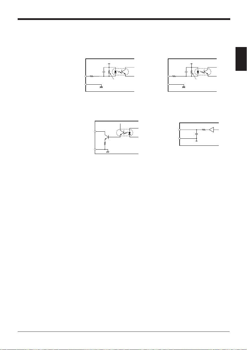
1.4 Input/output Circuits
Input circuit
TIMING, HOLD RESET ZERO, EXT1•2, OUTPUT DISABLE
+24 V
SYNC
Chapter 1 Preparation
+24 V
1
Output circuit
GND
3 kΩ
IN
470 Ω
GND
10 kΩ
IN
3 kΩ
HIGH, GO, LOW, STROBE MONITOR (analog voltage) output
NPN Output
GND
Output
0 V
100 Ω
0 V
NPN open-collector, 40 V, 100 mA max.
5
Page 16
Chapter 1 Preparation
1.5 Mounting
This section explains the mounting procedure for the controller and sensor head
and the wiring connections.
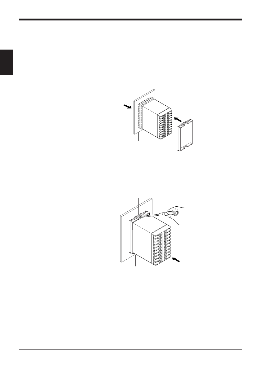
1.5.1 Mounting and dismounting the controller
1
Mounting
Insert the controller from the front of the panel and fix it using the panel mounting
frame.
Dismounting
1. Insert the controller.
Panel
While raising the catches at sections 1 and 2 with a flat blade screwdriver, push the
controller forward from the back.
1
2
2. Fix the controller using the
panel mounting frame.
Panel mounting frame
Push the controller forward.
6
Page 17
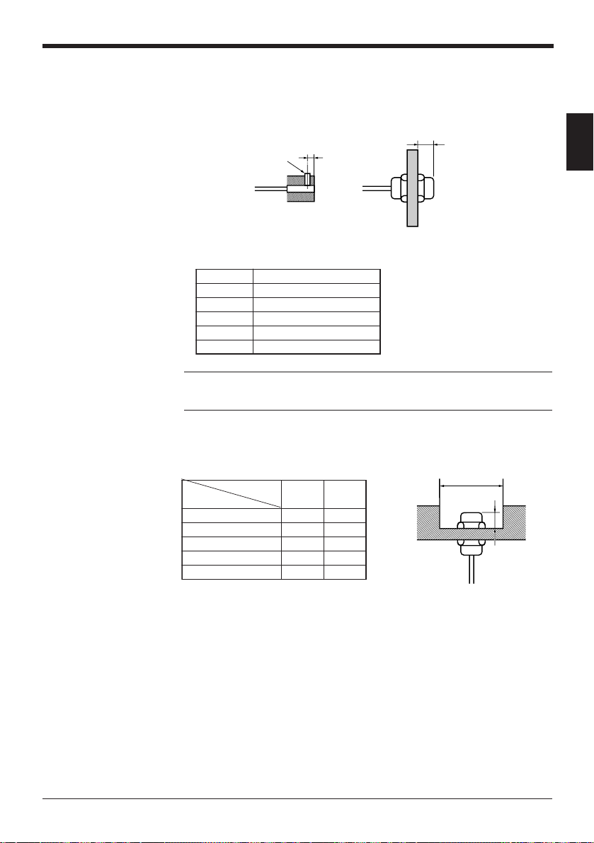
1.5.2 Mounting the sensor head
Mounting
• Tighten the EX-305V set screw and EX-110V nut away from the tip of the
sensor head as shown in the figure.
M3 set screw
EX-305V
• Referring to the measuring distance in the table below, determine the distance
between the tip of the sensor head and target.
ledoM)mm(ecnatsidgnirusaeM
V503-XE1
V011-XE2
V614-XE5
V224-XE01
V416-XE4
Note: After making the adjustment, do not change the position of the nut or screw.
If the position is changed, the output characteristics may change even when the
nut or screw is positioned in the range shown in the figure.
Flush-mounting
To flush-mount the sensor head in a metal base, follow the guidelines given in the
table below.
ledoM
V503-XE019
V011-XE219
V614-XE5301
V224-XE5502
V416-XE23x615
5 mm min.
)mm(ecnatsiD
AB
Chapter 1 Preparation
8 mm min.
1
EX-110V
øA
B
* The table above shows the dimensions to use when the metal base is iron.
* The table above shows the dimensions to satisfy the specifications when the
sensor head is flush-mounted after the output characteristics have been
adjusted with no metal present around the head.
7
Page 18
Chapter 1 Preparation
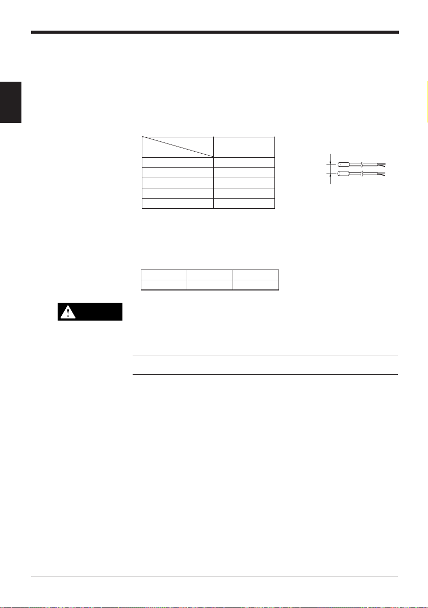
When mounting two or more sensor heads of the same model in parallel
• The sensor may not output the correct voltage due to mutual interference. Make
sure that the distance between sensor heads adjacent to each other is larger
than the values shown in the table below. (This allows the display resolution
specification to be satisfied when the number of measurements to average is
1
"64".)
• When two sensor heads are mounted in parallel, mutual interference can be
prevented by alternately oscillating the sensor heads using the synchronous
input terminal (
ledoM
➮
page 4
).
)mm(ecnatsiD
V503-XE08
V011-XE003
V614-XE056
V224-XE013
V416-XE542
Tightening torque
To tighten the EX-305V set screw, apply a torque of 0.2 N•m or less.
To tighten the nut of the other sensor heads, apply a torque shown in the table
below or less.
V011-XEV614-XEV224-XE
.xamm•N01.xamm•N02.xamm•N01
gnitnuomlellaraP
Parallel mounting
CAUTION
• If the applied tightening torque exceeds the specified one, the sensor
head may be deformed or malfunction.
• If the sensor cable is installed in the same conduit as high voltage lines or
power lines, the sensor may malfunction. Be sure to keep the wiring
separate.
Note: Do not change the sensor cable length (3 m). If the cable is extended or cut,
the characteristics will change.
8
Page 19
1.6 Adjustment
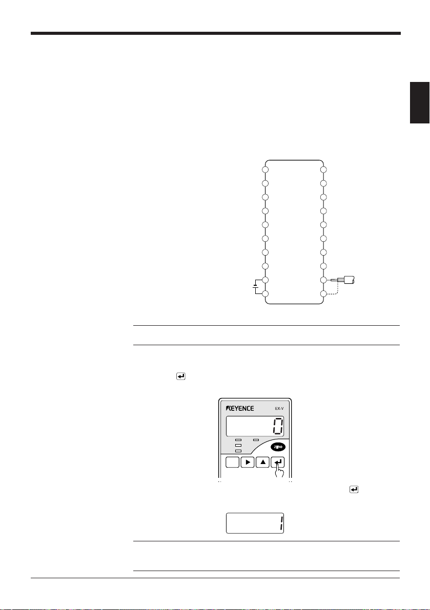
1.6.1 Connection
Chapter 1 Preparation
Though the EX-V series has been factory-adjusted, follow the procedure described
below to adjust the sensor using your actual target in order to satisfy the
specifications. When the sensor head has been replaced, be sure to make this
adjustment.
1. Connect the core and shielding wires of the sensor head to sensor head
connection terminals 11 and 12 of the controller.
1
2. After making the connection,
connect the power supply cable to
power supply terminals 1 and 2.
The POWER indicator on the
controller illuminates, and the
sensor enters the operation state.
24V DC
Note: Let the sensor warm up for 30 minutes or more after supplying power to it,
and then start the adjustment.
1.6.2 Adjusting the output characteristics
1. Press the key for at least 2 seconds.
The sensor displays "0" and enters the adjustment mode.
HIGH TIM
GO
LOW
SET
FUNC
UTILITY
–
+
MODE
10
9
8
7
6
5
4
3
2
1
Terminal block
CALL
CALIB
20
19
18
17
16
15
14
13
12
11
Sensor head
2. With no metal object present around the sensor head, press the
key.
The sensor displays "1" and moves to the next setting step.
Note 1: Do not touch the metal area of the sensor head with your hand.
Note 2: Make sure that no metal object is present within a radius of 15 centimeters
around the sensor head.
9
Page 20
Chapter 1 Preparation
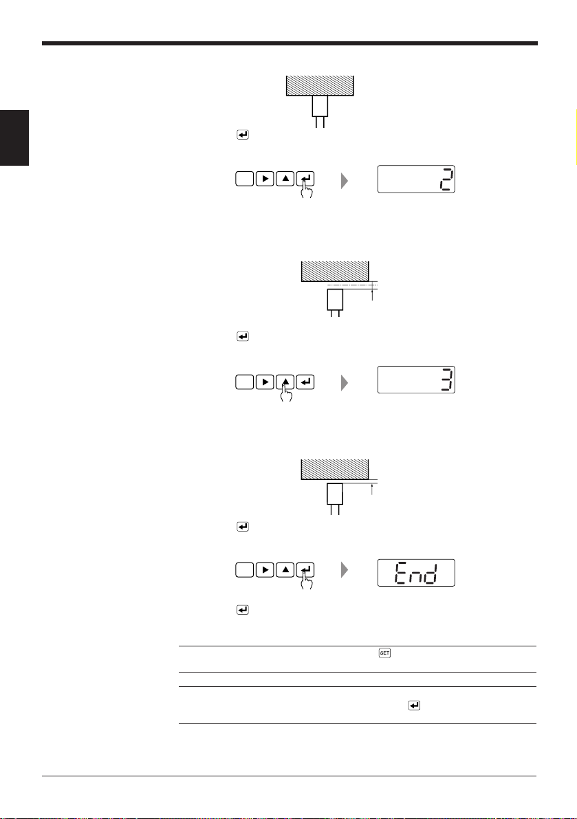
3. Bring the sensor head in contact with the target.
SET
key.
CALL
1
4. Press the
The sensor displays "2" and moves to the next setting step.
5. Move the sensor head.
Move the sensor head so that the distance between the sensor head and target
is the full scale of the measuring distance (maximum distance) of the sensor
head.
Full scale
6. Press the
key.
The sensor displays "3" and moves to the next setting step.
SET
CALL
7. Move the sensor head.
Move the sensor head so that the distance between the sensor head and target
is half the measuring distance (half scale).
Half scale
8. Press the
key.
The sensor displays "End".
SET
CALL
10
9. Press the
key to complete the adjustment.
The sensor starts measurement.
Reference: To stop the adjustment, press the key. Then, the sensor starts
measurement without making the adjustment.
Note: If the distance between the sensor head and target is improperly adjusted
during the adjustment, "Err 6" is displayed. Press the key to cancel the error,
and then readjust the distance.
Page 21

Chapter 2
Quick Guide to Basic Mode Operation
Explains the kinds of the measurement modes and the selection procedure.
Selecting the mode best suited to your detection purpose allows you to quickly
operate the sensor by easy setting.
2.1 Measurement Modes ........................................................... 12
2.1.1 Bottom-dead-center mode .....................................................12
2.1.2 Eccentricity/vibration mode .................................................... 12
2.1.3 Thickness/gap mode.............................................................. 13
2.1.4 Manual mode .........................................................................13
2.2 Quick Guide to Basic Mode Operation .............................. 14
2.2.1 Setting the bottom-dead-center mode ................................... 14
2.2.2 Setting the eccentricity/vibration mode ..................................18
2.2.3 Setting the thickness/gap mode............................................. 21
2.3 Auto-Zero Function ............................................................. 24
2.4 Tolerance Limit Value Setting ............................................ 25
2.5 Checking the Tolerance Limit Values
(Calling the tolerance limit values) .................................... 27
Page 22
Chapter 2 Quick Guide to Basic Mode Operation
2.1 Measurement Modes
The EX-V series provides the following four measurement modes: "Bottom-deadcenter mode", "Eccentricity/vibration mode", "Thickness/gap mode" (which are
basic modes for quick operation), and "Manual mode" (which allows users to
perform setting as desired). This section explains the major functions of each
mode.
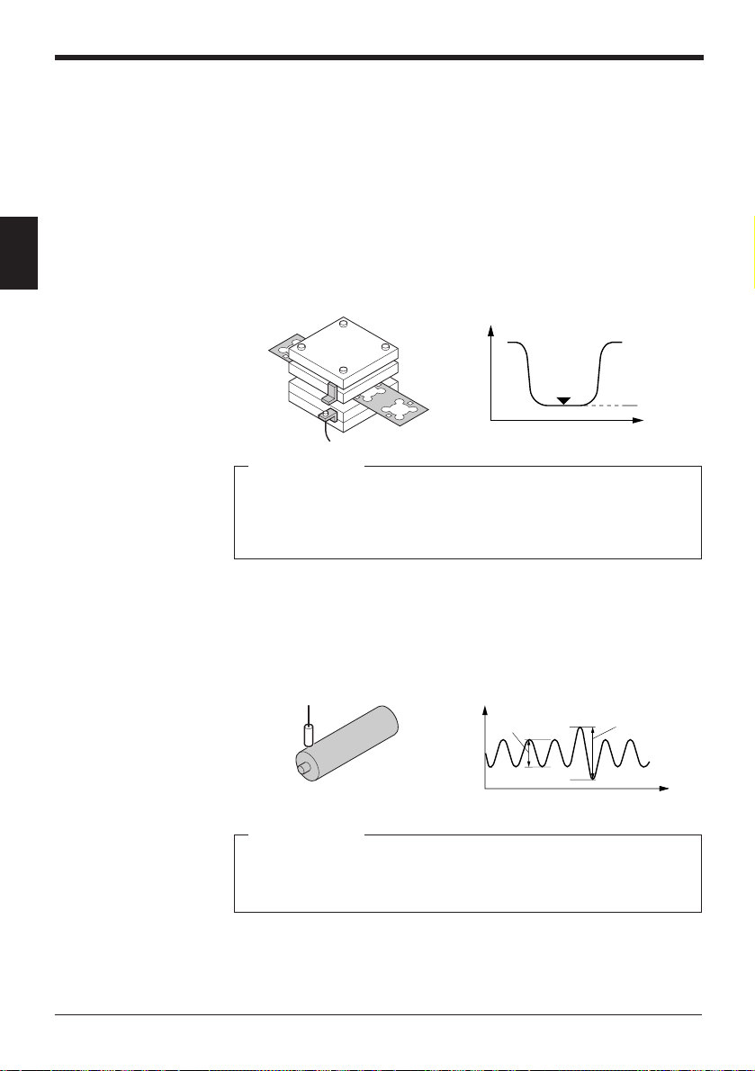
2.1.1 Bottom-dead-center mode
2
This mode is used to measure the displacement of the origin position of a machine
with stroke movements such as a press. When the displacement of the bottom
dead center or origin position is out of the preset tolerance range, the sensor
outputs an Alarm signal.
Major applications
• Detecting the bottom dead center position of a press
• Detecting the bottom dead center position of a press-fit machine
• Detecting the bottom dead center position of a welding machine
• Pressure control for a injection molding machine
• Measuring the depth of the recess on a piston head
Displacement
Bottom dead
center
Displayed value
Time
2.1.2 Eccentricity/vibration mode
This mode is used to measure the roller eccentricity or abnormal machine vibration.
When the amplitude of the runout or vibration is larger than the preset tolerance
limit value, the sensor outputs an Alarm signal.
Major applications
• Measuring roller eccentricity
• Measuring surface plate runout
• Detecting runout due to improper chucking
• Measuring drill bit eccentricity
12
OK
Displacement
NG
Time
Page 23
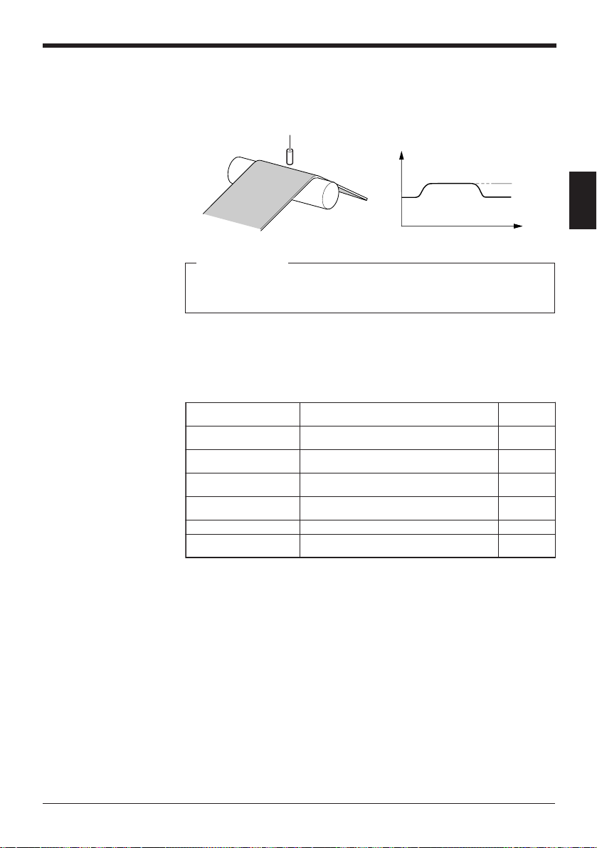
2.1.3 Thickness/gap mode
This mode is used to measure target thickness or gap with a direct reading value.
When the thickness or gap is larger or smaller than the preset upper or lower value
for the tolerance limit, the sensor outputs an Alarm signal.
Chapter 2 Quick Guide to Basic Mode Operation
Displayed value
2.1.4 Manual mode
Displacement
Time
Major applications
• Measuring hoop material thickness
• Checking grindstone abrasion
• Thickness control during polishing ceramic components
In addition to the modes above, the manual mode is available. The manual mode
provides the following six data processing modes to allow adaptable measurement.
For details, see pages that describe each data processing mode.
edomgnissecorpataDnoitcnuF
tnemerusaemlamroN
dlohkaeP
dlohmottoB
dlohkaep-ot-kaeP
dlohelpmaS.emitdeificepsataeulavehtserusaeM18
dlohegarevA
.ylsuounitnoc
.doirepdeificeps
.doirep
eulavderusaemehtstuptuo/syalpsiD
agnirudeulavmumixamehtserusaeM
deificepsagnirudeulavmuminimehtserusaeM
mumixamehtneewtebecnereffidehtserusaeM
.doirepdeificepsagnirudseulavmuminimdna
derusaemfoegarevaelpmisehtserusaeM
.doirepdeificepsagnirudseulav
egap
67
67
87
97
28
2
ecnerefeR
13
Page 24
Chapter 2 Quick Guide to Basic Mode Operation
2.2 Quick Guide to Basic Mode Operation
This section describes the major measurement modes and an easy setting
method.
2.2.1 Setting the bottom-dead-center mode
The following example explains how to mount the EX-V series to a press.
The basic operation is the same when mounting the EX-V series to other devices.
Be sure to adjust the output characteristics before performing the following procedure. (➮
2
Refer to page 9
1. Secure the sensor head to the lower die of the press.
• Referring to the figure below, prepare the sensor head mounting jig and a
target.
• Refer to pages 7 and 8 for the position of the sensor head nut and the tightening torque.
.)
Target
Sensor head
14
Note: Be sure to use an IRON target with sufficient area for detection. (➮
Reference: When the comparator output is already connected to the emergency
stop or another input for the facility, short-circuit the OUTPUT DISABLE input
(terminal 3) and grounding terminal (terminal 7) to disable the comparator output
before making the adjustment.
* After making the adjustment, be sure to disconnect these terminals to enable the
comparator output.
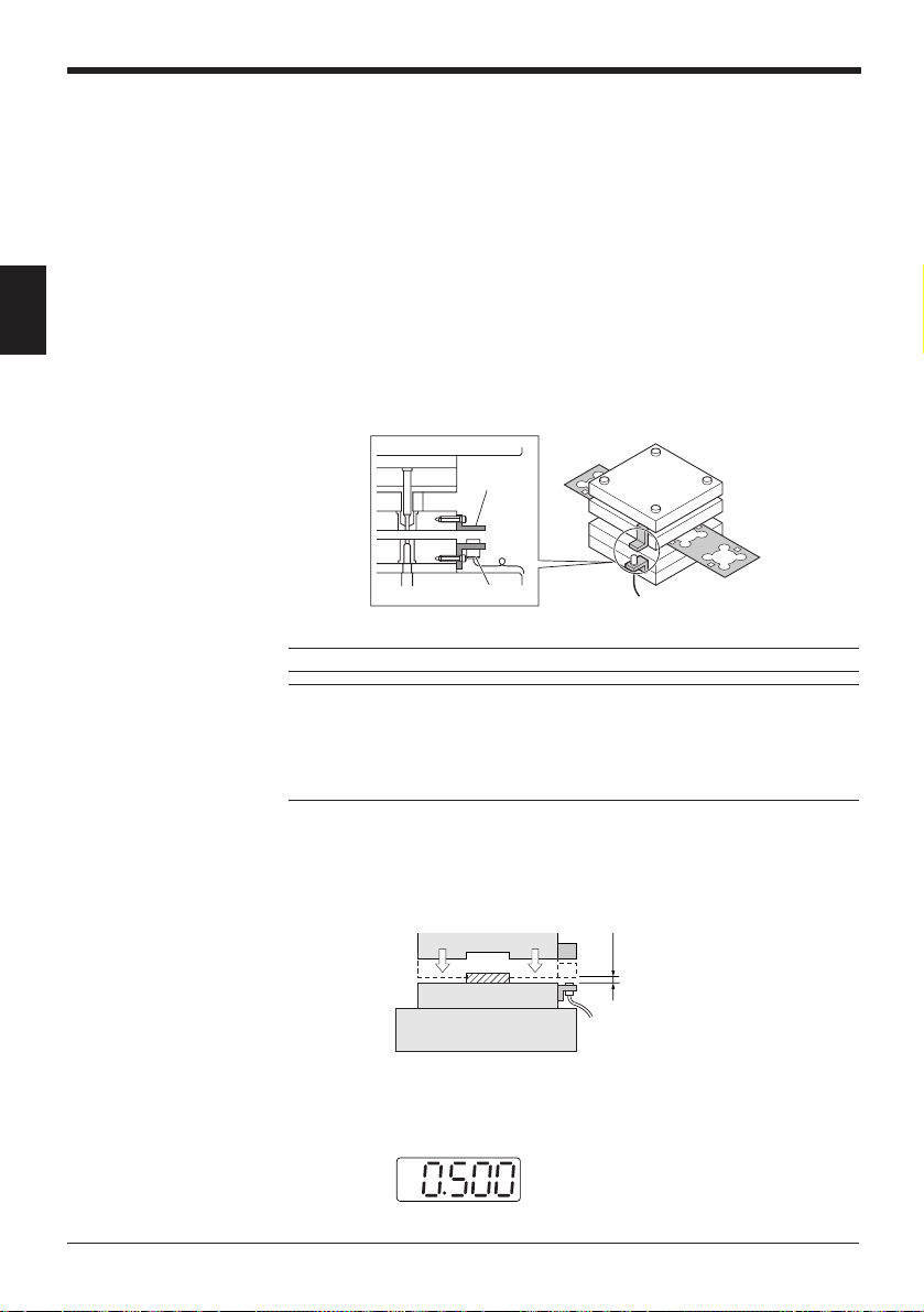
2. Adjust the distance between the sensor head and target.
Move the press an inch at a time and lower the stripper (or upper die) to the
bottom dead center position. (Refer to the figure below.)
Half the measuring range
Stripper or upper die
Lower die
Die set
Adjust the distance between the sensor head and target so that the distance
between them is about half the measuring distance when the stripper is in the
bottom dead center position. The controller’s display shows a value close to the
half scale.
of the sensor to be used.
In the case of the EX-305V,
the value is close to “0.5”.
p.95
)
Page 25
Chapter 2 Quick Guide to Basic Mode Operation
* The distance between the sensor head and target should be more than the full scale when the
stripper is in the top dead center position.
Sensor model
EX-305V 1 0.5
EX-110V 2 1
EX-416V 5 2.5
EX-422V 10 5
EX-614V 4 2
Measuring distance Half scale
(mm) (Full scale) (mm)
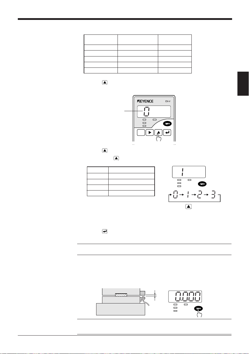
3. Press the key for at least 2 seconds.
The sensor enters the mode setting state and displays the mode number.
Mode No
HIGH TIM
GO
4. Press the
• Pressing the
LOW
SET
FUNC
UTILITY
key to display “1” which indicates the “bottom-dead-center” mode.
key changes the mode number sequentially.
MODE
CALL
CALIB
Mode No. Measurement mode
0 Manual
1 Bottom-dead-cente
2 Eccentricity/vibration
HIGH TIM
GO
LOW
3 Thickness/gap
key
• The measurement mode is factory-set to manual.
➮
For the initial setting of each measurement mode, refer to “4.1 Table of Data Processing
Functions” on page 46.
5. Press the key to save the measurement mode setting.
The sensor returns to the measurement state.
Note: Changing the measurement mode initializes all preset values except for the
tolerance limit values.
2
6. Activate the machine and check the bottom dead center position during normal
operation. Press the [ZERO] key to set this position as the reference point.
When the [ZERO] key is pressed, “0000” appears on the measured value
display.
Stripper or upper die
Lower die
Die set
Reference: To compensate for the slight variation in the bottom dead center
position at press startup or the influence of temperature fluctuation, refer to “Previous value comparison function [d]” on page 56.
Normal bottom
dead center
HIGH TIM
GO
LOW
15
Page 26
Chapter 2 Quick Guide to Basic Mode Operation
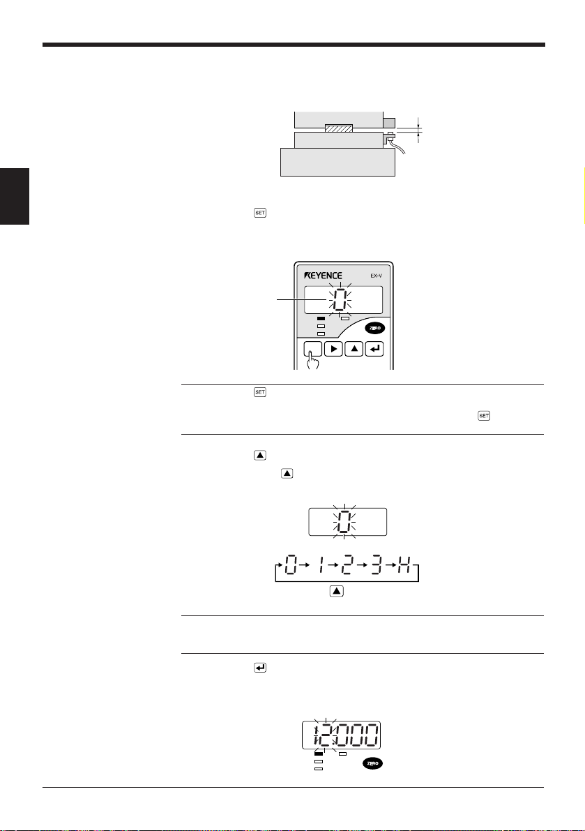
7. Set the upper value for the tolerance limit.
For a press, set the threshold value to the amount of the rise of the bottom dead
center due to swarf.
Stripper or upper die
Lower die
Die set
Upper limit value
2
1) Press the
• The sensor enters the tolerance limit setting mode.
• The setting number is displayed.
Note: Press the key for a short time. When the key is pressed for 2 seconds or
longer, the sensor enters the function setting mode and displays “Ab[d”. If you
accidentally put the sensor into the function setting mode, press the key again
to return to the measurement state.
2) Press the
• Pressing the
•“x” indicates the hysteresis setting. (➮
key.
Mode No
HIGH TIM
GO
LOW
SET
FUNC
UTILITY
MODE
CALL
CALIB
key to display the desired setting number.
key changes the setting number sequentially.
key
Refer to page 85.
)
16
Reference: Four kinds of tolerance limit values (“0” to “3”) can be saved in the
memory. The registered setting numbers can be switched using external signals.
(➮
Refer to page 4.
3) Press the
)
key.
• The sensor automatically enters the HIGH limit value setting mode.
• The setting value is displayed in red and the HIGH indicator illuminates.
HIGH TIM
GO
LOW
Page 27
Chapter 2 Quick Guide to Basic Mode Operation
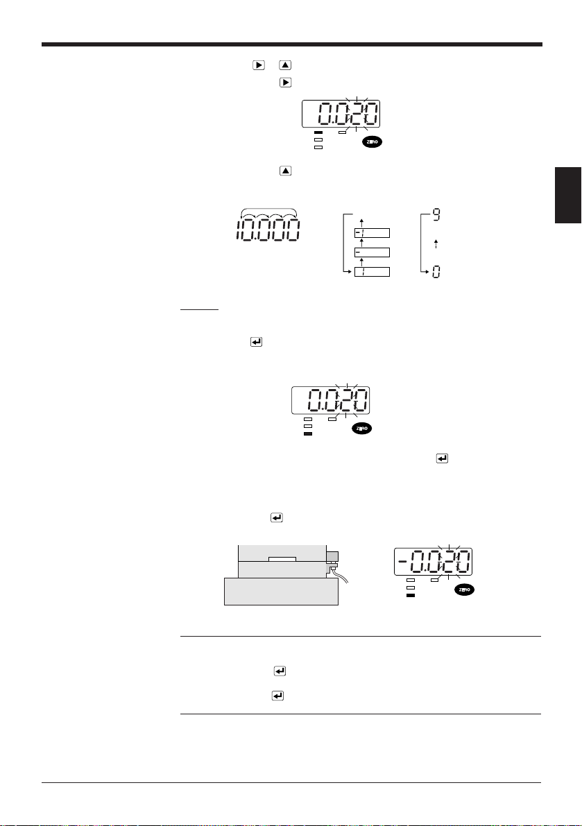
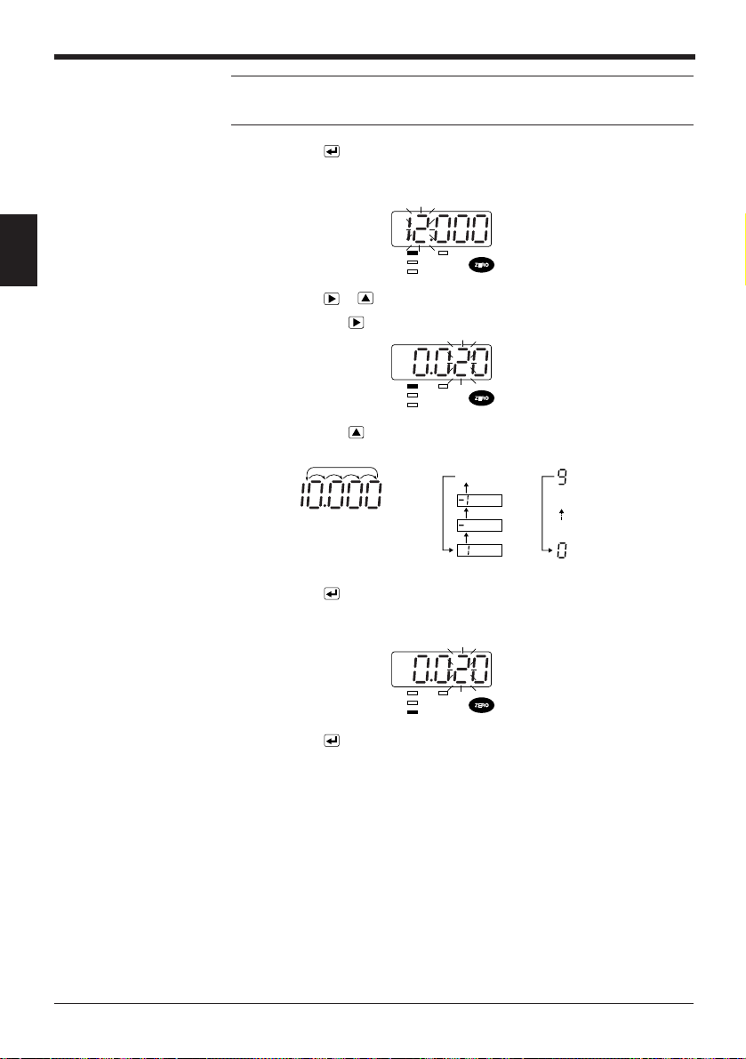
4) Press the or key to display the desired value.
• Pressing the
key changes the flashing digit to the right.
HIGH TIM
GO
LOW
• Pressing the
key changes the value.
• All digits flash when the fifth digit and sign can be changed.
No setting
(5th digit)
(1st to 4th digits)
Example
When setting the tolerance to +20 µm, specify “0020”.
5) Press the
key.
The HIGH limit setting value is saved. The sensor automatically enters the
LOW limit value setting mode.
HIGH TIM
GO
LOW
8. Set the lower value for the tolerance limit and press the
key.
• For a press, set the threshold value to the amount of the lowering of the
bottom dead center due to the absence of a target.
• Set the LOW limit value using the same procedure as in steps 7 3) and 4),
and press the
key to save the value.
Stripper or upper die
Lower die
Die set
HIGH TIM
GO
LOW
2
Note 1: The output is disabled during the tolerance limit value setting. When the
output is already on, however, the output is retained.
Note 2: Pressing the
key does not save the changes if [HIGH setting value –
Hysteresis] is smaller than [LOW setting value + Hysteresis]. In this case, “Err1” is
displayed. Press the
key again to cancel the error, and then specify the correct
values.
17
Page 28

Chapter 2 Quick Guide to Basic Mode Operation
2.2.2 Setting the eccentricity/vibration mode
The following example explains the procedure for roller eccentricity measurement.
The basic operation is the same when mounting the EX-V series to other devices.
Be sure to adjust the output characteristics before performing the following
procedure (
➮
page 9
1. Mount the sensor head to the machine.
➮
For the sensor head mounting procedure, read "Mounting the sensor head" (pages 7 and 8).
2
).
Note: Be sure to use an IRON target with sufficient area for detection. (
➮
page 95
Reference: When the comparator output is already connected to the emergency
stop or another input for the facility, short-circuit the OUTPUT DISABLE input
(terminal 3) and grounding terminal (terminal 7) to disable the comparator output
before making the adjustment.
* After making the adjustment, be sure to disconnect these terminals to enable
the comparator output.
2. Press the
key for at least 2 seconds.
The sensor enters the mode setting state and displays the mode number.
Mode No.
HIGH TIM
GO
3. Press the
LOW
SET
FUNC
UTILITY
key to display "2" which indicates the "eccentricity/vibration"
MODE
CALL
CALIB
mode.
• Pressing the
0launaM
1retnec-daed-mottoB
2noitarbiv/yticirtneccE
3pag/ssenkcihT
key changes the setting number sequentially.
.oNedoMedomtnemerusaeM
HIGH TIM
GO
LOW
)
18
key
Page 29
Chapter 2 Quick Guide to Basic Mode Operation
• The measurement mode has been factory-set to manual.
➮
For the initial setting of the functions for each measurement mode, refer to "4.1 Table of Data
Processing Functions" (page 46).
4. Press the key to save the measurement mode setting.
The sensor returns to the measurement state.
Note: Changing the measurement mode initializes all preset values except for the
tolerance limit values.
5. Activate the machine and check the runout value during normal operation.
The value displayed in this step is the runout per cycle.
6. Set the upper value for the tolerance limit.
Calculate the upper limit value by adding the upper limit value of the required
tolerance to the value displayed during normal operation, and set the value as
the HIGH limit value.
Example
When the runout value during normal operation is "10 µm" and the tolerance is
"+30 µm", set the HIGH limit value to "0.040". When the runout value exceeds "40
µm", the comparator output is turned on.
1) Press the
key.
• The sensor enters the tolerance limit setting mode.
• The setting number is displayed.
Setting No.
HIGH TIM
GO
LOW
SET
FUNC
UTILITY
MODE
CALL
CALIB
Note: Press the key for a short time. When the key is pressed for 2 seconds or
longer, the sensor enters the function setting mode and displays "Ab(d". If you
accidentally put the sensor into the function setting mode, press the key again
to return to the measurement state.
2
2) Press the
• Pressing the
key to display the desired setting number.
key changes the setting number sequentially.
• "x" indicates the hysteresis setting (
➮
page 85
key
).
19
Page 30
Chapter 2 Quick Guide to Basic Mode Operation
Reference: Four kinds of tolerance limit values ("0" to "3") can be saved in the
memory. The registered setting numbers can be switched using external signals
(
➮
page 4
).
3) Press the
key.
• The sensor automatically enters the HIGH limit value setting mode.
• The setting value is displayed in red and the HIGH indicator illuminates.
2
4) Press the
• Pressing the
• Pressing the
or key to display the desired value.
HIGH TIM
GO
LOW
key changes the flashing digit to the right.
HIGH TIM
GO
LOW
key changes the value.
• All digits flash when the fifth digit and sign can be changed.
No setting
(5th digit)
(1st to 4th digits)
5) Press the key.
The HIGH limit setting value is saved. The sensor automatically enters the
LOW limit value setting mode.
20
HIGH TIM
GO
LOW
6) Press the
key again.
7. Activate the machine to check whether the comparator output correctly works
according to the tolerance limit setting values.
• The GO comparator output indicator on the controller illuminates when the
measured value is within the tolerance range. The HIGH indicator illuminates
when the measured value is higher than the upper limit value. The LOW
indicator illuminates when the measured value is lower than the lower limit
value.
• To perform fine adjustment of the tolerance limit values, repeat steps 5) and
6) described above.
Page 31

2.2.3 Setting the thickness/gap mode
The following example explains the procedure for sheet material thickness
measurement.
The basic operation is the same when mounting the EX-V series to other devices.
Be sure to adjust the output characteristics before performing the following
procedure (
1. Mount the sensor head to the machine.
➮
page 9
).
➮
For the sensor head mounting procedure, read "Mounting the sensor head" (pages 7 and 8).
Chapter 2 Quick Guide to Basic Mode Operation
2
Note: Be sure to use an IRON target with sufficient area for detection. (
➮
page 95
Reference: When the comparator output is already connected to the emergency
stop or another input for the facility, short-circuit the OUTPUT DISABLE input
(terminal 3) and grounding terminal (terminal 7) to disable the comparator output
before making the adjustment.
* After making the adjustment, be sure to disconnect these terminals to enable
the comparator output.
2. Press the
The sensor enters the mode setting state and displays the mode number.
3. Press the
• Pressing the
key for at least 2 seconds.
GO
LOW
SET
FUNC
UTILITY
MODE
CALIB
CALL
Mode No.
key to display "3" which indicates the "thickness/gap" mode.
key changes the setting number sequentially.
key
.oNedoMedomtnemerusaeM
0launaM
1retnec-daed-mottoB
2noitarbiv/yticirtneccE
3pag/ssenkcihT
)
• The measurement mode has been factory-set to manual.
➮
For the initial setting of the functions for each measurement mode, refer to "4.1 Table of Data
Processing Functions" (page 40).
21
Page 32

Chapter 2 Quick Guide to Basic Mode Operation
4. Press the key to save the measurement mode setting.
The sensor returns to the measurement state.
Note: Changing the measurement mode initializes all preset values except for the
tolerance limit values. If you accidentally put the sensor into the function setting
mode, press the key again to return to the measurement mode.
5. Set the upper value for the tolerance limit.
• Place the reference target in the correct measuring position and check the
2
• Calculate the upper limit value by adding the upper limit value of the required
Example
When the normal thickness measurement is "1 mm" and the tolerance is "±0.1
mm", set the HIGH limit value to "1.100" and the LOW limit value to "0.900".
normal thickness measurement.
tolerance to the normal thickness measurement, and set the value as the
HIGH limit value.
1) Press the
key.
• The sensor enters the tolerance limit setting mode.
• The setting number is displayed.
Setting No.
HIGH TIM
GO
LOW
SET
FUNC
UTILITY
MODE
CALL
CALIB
Note: Press the key for a short time. When the key is pressed for 2 seconds or
longer, the sensor enters the function setting mode and displays "Ab(d". If you
accidentally put the sensor into the function setting mode, press the key again
to return to the measurement state.
2) Press the
• Pressing the
• "x" indicates the hysteresis setting (
key to display the desired setting number.
key changes the setting number sequentially.
➮
page 85
).
key
Reference: Four kinds of tolerance limit values ("0" to "3") can be saved in the
memory. The registered setting numbers can be switched using external signals (
page 4
).
3) Press the
key.
• The sensor automatically enters the HIGH limit value setting mode.
• The setting value is displayed in red and the HIGH indicator illuminates.
➮
22
HIGH TIM
GO
LOW
Page 33

Chapter 2 Quick Guide to Basic Mode Operation
4) Press the or key to display the desired value.
• Pressing the
• Pressing the
key changes the flashing digit to the right.
HIGH TIM
GO
LOW
key changes the value.
• All digits flash when the fifth digit and sign can be changed.
No setting
2
(1st to 4th digits)
5) Press the
(5th digit)
key.
The HIGH limit setting value is saved. The sensor automatically enters the
LOW limit value setting mode.
6. Set the lower value for the tolerance limit.
• Set the lower limit value.
• Use procedures 3) and 4) in step 5 to set the LOW limit value. Then, press
key to save the value.
the
HIGH TIM
GO
LOW
Note 1: The output is disabled during the tolerance limit value setting. When the
output is already on, however, the output is retained.
Note 2: Pressing the
key does not save the changes if [HIGH setting value -
Hysteresis] is smaller than [LOW setting value + Hysteresis]. In this case, "Err1" is
displayed. Press the
key again to cancel the error, and then specify the correct
value.
Reference: When the thickness/gap mode is selected, in the initial setting state the
measured value becomes larger as the distance between the sensor head and
target is shorter. When you want to make the measured value smaller as the
distance is shorter, set function "d" (inverse/normal display function) to normal.
For details, see page 73.
Direction in which the
measured value increase
23
Page 34

Chapter 2 Quick Guide to Basic Mode Operation
2.3 Auto-Zero Function
The displayed value can be instantaneously reset to "0000" by pressing the
[ZERO] key or input through the AUTO-ZERO input terminal. The increase or
decrease in the value measured after activating the auto-zero function can be
displayed using "±" (plus or minus). This function simplifies zero-point adjustment
at product type changeovers.
Using the front panel key
• Press the [ZERO] key to reset the displayed value to "0000".
2
Using the AUTO-ZERO input terminal
• The value displayed just as the key is released is reset to "0000".
Short-circuit the ZERO 4 and GND 7 terminals to activate the auto-zero function.
HIGH TIM
GO
LOW
SET
CALL
GND
TIMING
67
RESET
5
ZERO
4
or
GND
TIMING
67
RESET
5
ZERO
4
Canceling the auto-zero function (Restoring the value reset using the auto-zero function)
Press the [ZERO] key for 3 seconds to cancel the auto-zero function.
Note 1: When an offset value is set, the offset value is displayed when the autozero function is activated. For details, see "Offset function [x]" (
➮
Note 2: When using the internal trigger function (
page 46
➮
pages 40 and 41
), adjust the trigger
level after activating the auto-zero function. (The internal trigger function works with
regard to the value displayed after the auto-zero function is activated.)
CAUTION
If frequently activating the auto-zero function using the external input
terminal, set the panel-lock function to ON to protect the memory. Then, the
displayed value will not be stored in the internal memory.
For details of the panel-lock function, see "Panel-lock function [J]"
(➮ page 43).
).
24
Page 35

2.4 Tolerance Limit Value Setting
You can set the allowable range for the tolerance limit value. After the comparator
of measured values, signals are output at three levels: when the measured value
exceeds the upper limit (HIGH), when it is below the lower limit (LOW), and when it
is within the allowable range (GO). The measured value is displayed in green for
the GO output and in red for the HIGH and LOW outputs.
Chapter 2 Quick Guide to Basic Mode Operation
Operation diagram
HIGH limit value
LOW limit value
Displayed value
HIGH OUT
GO OUT
LOW OUT
Setting the tolerance limit values
1. Press the key.
• The sensor enters the tolerance limit setting mode.
• The setting number is displayed.
(v)
ON
OFF
ON
OFF
ON
OFF
Setting No.
*
*
When a signal is output, the comparator output indicator on the
controller’s front panel illuminates.
* With the factory setting, a hysteresis of 5 digits is applied
when the output changes from LOW to GO or HIGH to GO.
HIGH TIM
GO
LOW
SET
FUNC
UTILITY
MODE
CALL
CALIB
2
(t)
2. Press the
Pressing the
key to display the desired setting number.
key changes the setting number sequentially.
key
25
Page 36

Chapter 2 Quick Guide to Basic Mode Operation
3. Press the key.
• The sensor automatically enters the HIGH limit value setting mode.
• The setting value is displayed in red and the HIGH indicator illuminates.
HIGH TIM
GO
LOW
2
Note: Setting the panel-lock function to ON allows the terminals to switch the
setting number for the tolerance limits. For details of the panel-lock function, see
"Panel-lock function [ ]" (➮
4. Press the
or key to display the desired value.
• Pressing the
• Pressing the
page 43
W
).
key changes the flashing digit to the right.
key changes the value.
• All digits flash when the fifth digit and sign can be changed.
No setting
HIGH TIM
GO
LOW
5. Press the
(5th digit)
key.
(1st to 4th digits)
• The HIGH limit setting value is saved. The sensor automatically enters the
LOW limit value setting mode.
• Set the LOW limit value using the same procedure as in steps 3 and 4.
HIGH TIM
GO
LOW
Note 1: The output is disabled during the tolerance limit value setting. When the
output is already on, however, the output is retained.
Note 2: Pressing the
key does not save the changes if [HIGH setting value -
Hysteresis] is smaller than [LOW setting value + Hysteresis]. In this case, “Err1” is
displayed. Press the
key again to cancel the error, and then specify the correct
values.
26
Page 37

Chapter 2 Quick Guide to Basic Mode Operation
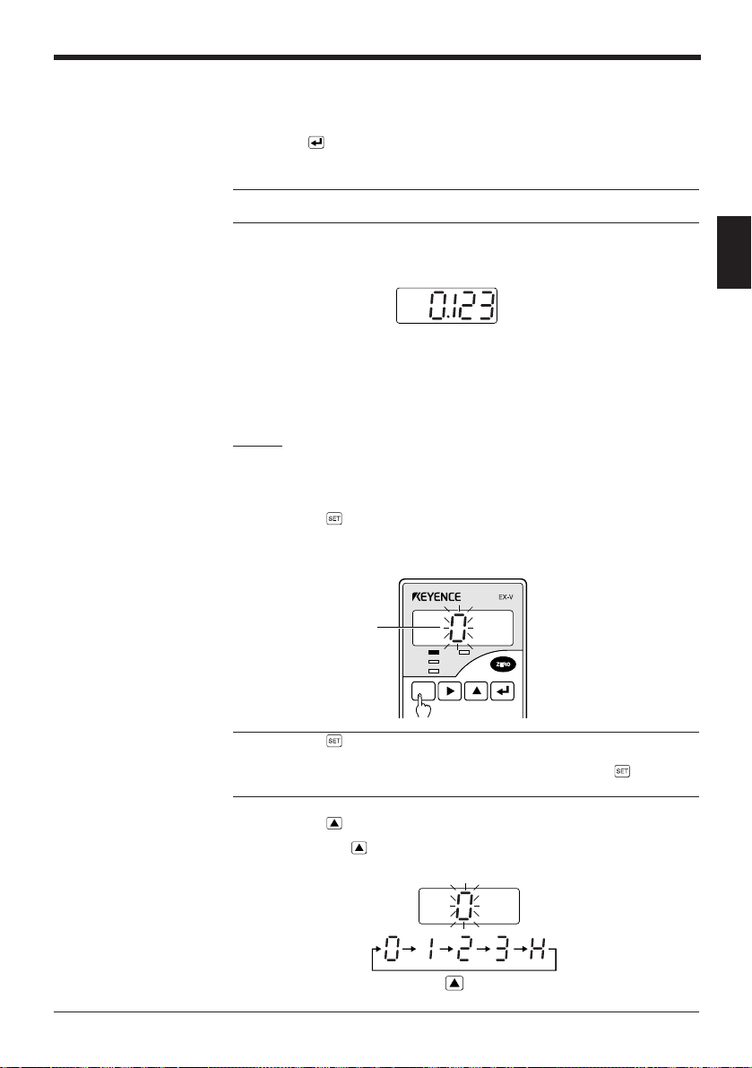
2.5 Checking the Tolerance Limit Values (Calling the tolerance limit values)
The preset tolerance limit values can be checked during measurement.
1. Press the
key.
The preset setting number ("0" through "3") is displayed.
Setting No.
HIGH TIM
GO
LOW
SET
FUNC
UTILITY
MODE
CALL
CALIB
Note: Press the key for a short time. When the key is pressed for 2 seconds or
longer, the sensor enters the adjustment mode. If you accidentally put the sensor
into the adjustment mode, "0" appears at the right end on the display. At this time,
press the key to return to the measurement state.
2. Press the
key.
The HIGH indicator flashes and the preset HIGH limit value appears on the
display.
HIGH TIM
GO
LOW
3. Press the
key again.
The LOW indicator flashes and the preset LOW limit value appears on the
display.
2
HIGH TIM
GO
LOW
4. Press the
key to return to measured value display.
Note 1: The EX-V series internally performs measurement and comparison even
while displaying the tolerance limit value. When the measured value exceeds the
tolerance limit value while the tolerance limit value is called out on the display, the
displayed value changes from green to red to indicate that the measured value is
out of the tolerance range.
Note 2: When you want to change the preset value while calling out the tolerance
limit value on the display, press the
limit setting mode. Refer to "2.4 Tolerance Limit Value Setting" (
26
).
key. This allows you to enter the tolerance
➮
pages 25 and
27
Page 38

Chapter 2 Quick Guide to Basic Mode Operations
MEMO
Page 39

Chapter 3
Use of Common Functions
Explains the functions common to the respective modes and the setting procedure.
3.1 Table of Functions and Function Numbers....................... 30
3.2 Function Setting Flow ......................................................... 31
3.2.1 Selecting the function using the
3.2.2 Display scaling function [E] .................................................... 33
3.2.3 Monitor (analog voltage) output setting function [F] ............... 36
3.2.4 Digits function/decimal point function [g] ............................... 39
3.2.5 Offset function [x]................................................................... 40
3.2.6 Output form selection function [I] ..........................................42
3.2.7 Panel-lock function [j] ........................................................... 43
key .................................31
Page 40

Chapter 3 Use of Common Functions
3.1 Table of Functions and Function Numbers
Use the operation keys to set the functions of each mode. This section describes
the table of functions "E" through "J".
Table of functions and function numbers
noitcnuF
edoc
e
f
3
g
x
i
j
* The setting in each shaded column of the table above shows the factory-set value.
noitcnuF
gnilacsyalpsiDulavdeyalpsidehtrofnoitcnufgnilacsehtgnitteS
rotinoM
gnittestuptuo
stigiD
tnioplamiceD
tesffO 000.0:eulavlaitini(eulavciremunehtgnitteS
mroftuptuO
kcol-lenaP
)noitceles(
0123456789
)egatlovgolana(
dohtem
stigid5stigid5stigid5stigid5stigid4stigid4stigid4
tigidht4tigiddr3tigiddn2
.O.N
lamroN
FFO
.C.N
lamroN
NO
-ret(
)lanim
oN
lamiced
tniop
.O.N
.O.N
dloH
yaled-ffO
e
tigidht4tigiddr3tigiddn2tigiddn2
)
.oNnoitcnuF
tuptuoehtgnitcelesdnatuptuo)egatlovgolana(rotinomehtrofnoitcnufgnilacsehtgnitteS
-hgiH
ycarucca
edom
30
Page 41

3.2 Function Setting Flow
This section explains how to set functions "E" through "j" using the key.
3.2.1 Selecting the function using the key
Select the function to be set from functions "E" through "j" and then enter the
desired function number or numeric value.
Chapter 3 Use of Common Functions
1. Press the
key for at least 2 seconds.
• The sensor enters the common function selection mode.
• The function parameter of the flashing function code can be set.
HIGH TIM
GO
2. Press the
Pressing the
SET
3. Press the
LOW
SET
FUNC
UTILITY
key to select the function to be set.
key changes the flashing digit to the right.
CALL
or key to enter the function number setting state.
MODE
CALL
CALIB
4. Set the function parameter.
➮
For details of each function, see pages 33 to 43.
3
5. Press the key.
The sensor saves the setting and returns to the measurement state.
6. To set two or more functions, repeat steps 1 through 5 described above.
31
Page 42

Chapter 3 Use of Common Functions
3
Reference 1: When the initial setting for a function is changed, the setting is
displayed in red.
Reference 2: To return to the common function selection mode without changing
the setting, press the key.
Note 1: When you return to the measurement state by pressing the key even
after entering a function number or numeric value, the number or value is not
saved.
Note 2: The output is disabled for the time between entering the common function
selection mode with the
setting. However, if the output is already on before the sensor enters the common
function selection mode, the output is retained.
key and returning to the measurement state after
32
Page 43

3.2.2 Display scaling function [E]
This function is used to change the ratio of the displayed value relative to the
measured value (input value from the sensor head). To perform scaling, enter the
desired display value respectively for two desired correction points.
Example
To display the original display value changing from "1" to "5" as a value changing
from "0" to "10"
Before scaling After scaling
Display Display
5
1
15
Original display
10
0
1
Original display
Chapter 3 Use of Common Functions
Setting
Point 1
Original display (input value) : 1.000
Changed display (display value) : 0.000
Point 2
Original display (input value) : 5.000
Changed display (display value) : 10.000
5
3
1. Press the
key for at least 2 seconds.
The sensor enters the common function selection mode.
2. Press the
key to select function "E".
Check that "E" is flashing.
HIGH TIM
GO
3. Press the
4. Press the
LOW
SET
FUNC
UTILITY
key to enter the display scaling function setting state.
key to select the input method. After the selection, press the
MODE
CALL
CALIB
key to save the input method setting.
• Pressing the
.oN
0-nI
1-nI
key changes the input method number.
noitcnuF
noitcnuF
gnittesrof
tupniyeknoitarepognisU
morfeulavtupnignisU
gnittesrofdaehrosnes
Using input value from
sensor head for setting
Using operation key
input for setting
• Select "0" or "1" and follow the procedure described below according to the
selected input method.
33
Page 44

Chapter 3 Use of Common Functions
When selecting "In-0"
5. Set the input value for correction point 1.
Use the
• The value on the flashing digit can be changed.
• Pressing the
3
• Pressing the
• All digits flash when the fifth digit and sign can be changed.
6. Press the
enters the display value setting state.
The display value is displayed in green.
7. Set the display value for correction point 1 in the same procedure as step 5, and
use the
or key to set the desired numeric value.
key changes the flashing digit to the right.
key changes the value.
key to save the input value for correction point 1. Then, the sensor
key to save the setting value.
No setting
(5th digit)
(1st to 4th digits)
34
8. Set and save the input and display values for correction point 2.
• Repeat steps 5 and 6 to set and save the input and display values for
correction point 2.
• After saving the display value for point 2, the sensor returns to the
measurement state.
Page 45

When "In-1" is selected
Chapter 3 Use of Common Functions
5. Set and save the input value for correction point 1 using the value measured by
the sensor (input from the sensor head).
• Move the sensor head or target to the distance to be set as correction point
1.
• Press the
key to save the measured value.
6. Use the
• Pressing the
• Pressing the
• All digits flash when the fifth digit and sign can be changed.
7. Press the
8. Set and save the values for correction point 2.
• Repeat steps 5 through 7 to set and save the input and display values for
• After saving the display value for point 2, the sensor returns to the
Note 1: The input and display values for display scaling can be set between 19999 and +19999.
Note 2: To set the scaling function, be sure to satisfy the following conditions. If
these conditions are not satisfied, "Err2" is displayed and the setting procedure is
disabled. When the error message is displayed, press the
error message and retry the setting.
(1) Input value 1 - input value 2 ≠ 0
(2) Display value 1 - display value 2 ≠ 0
(3) After scaling, the display value is within the range of ±19.999 when the input
value is "0".
(4)
0.0001 ≤
Note 3: When using the internal trigger function (
level after performing scaling. (The internal trigger function works with regard to the
value displayed after scaling is performed.)
or key to set the display value for correction point 1.
key changes the flashing digit to the right.
key changes the value.
No setting
(5th digit)
key to save the setting value.
correction point 2.
measurement state.
(display value 1 - display value 2 )
(input value 1 - input value 2)
≤ 15
➮
page 46
(1st to 4th digits)
key to cancel the
), adjust the trigger
3
35
Page 46

Chapter 3 Use of Common Functions
3.2.3 Monitor (analog voltage) output setting function [F]
This function is used to change the ratio of the analog voltage output value relative
to the displayed value, provided that the output voltage is between -5 and +5 V. By
performing scaling, you can change the output voltage value to the desired level. In
addition, you can select either of the following two output methods: one outputs
analog voltage according to the displayed value and the other outputs the input
value from the sensor head.
Reference: The initial state outputs the voltage equal to the displayed value.
Output scaling
The ratio of the analog voltage output relative to the displayed value can be
changed, provided that the output voltage is between -5 and +5 V. To perform
scaling, enter the desired monitor (analog voltage) output value respectively for two
3
desired correction points.
Before scaling
Monitor (analog voltage)
output (V)
55
5.000
1. Press the
After scaling
Monitor (analog voltage)
output (V)
Display
00
10.000
Display
key for at least 2 seconds.
The sensor enters the common function selection mode.
Setting
Point 1
Display value: 0.00
Monitor (analog voltage) output value: 0
Point 2
Display value: 10.000
Monitor (analog voltage) output value: 5
36
2. Press the
3. Press the
4. Press the
key to make "F" flash.
or key to enter the monitor output setting mode.
key with "F-0" displayed.
The sensor enters the monitor output scaling setting state.
Page 47

5. Set the display value for correction point 1.
The display value is displayed in red.
Chapter 3 Use of Common Functions
• The value on the flashing digit can be changed.
• Pressing the
• Pressing the
• All digits flash when the fifth digit and sign can be changed.
6. Press the
• Then, the sensor enters the monitor output value setting state.
7. Set the monitor output value for correction point 1 in the same procedure as
step 5, and use the
• The monitor output value is displayed in green.
8. Repeat steps 5 through 7 to set and save the display and monitor output values
for correction point 2.
• After saving the monitor output value for point 2, the sensor returns to the
measurement state.
key changes the flashing digit to the right.
key changes the value.
No setting
(1st to 4th digits)(5th digit)
key to save the display value for correction point 1.
key to save the setting value.
3
Note 1: The display and monitor output values for monitor output scaling can be
set between -19999 and +19999.
Note 2: To set the scaling function, be sure to satisfy the following conditions. If
these conditions are not satisfied, "Err3" is displayed and the setting procedure is
disabled. When the error message is displayed, press the
error message and retry the setting.
(1) Display value 1 - display value 2 ≠ 0
(2) Monitor output value 1 - monitor output value 2 ≠ 0
(3)
(monitor output value 2 - monitor output value 1 )
0.001 ≤
(display value 2 - display value 1)
key to cancel the
≤ 6
37
Page 48

Chapter 3 Use of Common Functions
Selecting the output method
1. Press the key for at least 2 seconds.
The sensor enters the common function selection mode.
2. Press the
3. Press the
key to make "F" flash.
or key to enter the monitor output setting mode.
3
4. Press the
Press the
5. Select the desired output method.
Pressing the
key to display "F-1".
key to enter the monitor output method selection state.
key changes the function number.
noitcnuF
.oN
01-f
11-f
noitcnuF
golanastuptuorosnesehT
ehtotgnidroccaegatlov
.eulavdeyalpsid
ehtgniretlifrognilacsretfA
ehtmorftupnilangis
rosneseht,daehrosnes
.langisehtstuptuo
Outputs the input value.
Outputs the displayed value.
38
Reference: When using the hold mode in the bottom-dead-center or eccentricity/
vibration mode (in which only the operation result is retained and displayed), set
the output method to "F-11". This allows you to check the current change of the
measured value.
6. Press the
After saving the setting, the sensor returns to the measurement state.
key to save the output method setting.
Page 49

3.2.4 Digits function/decimal point function [g]
The digits function is used to delete the last digit on the display. The decimal point
function is used to place the decimal point on the desired position.
Chapter 3 Use of Common Functions
Table of function number
Setting function "g"
.oNnoitcnuF
0
1
2
3
4
5
6
7*
* Only with the 1-mm type and 2-mm type, the high-accuracy mode can be used. The least significant
digit shows sub-micron.
forebmuN
stigiddeyalpsid
stigid5tigidht4
stigid5tigiddr3
stigid5tigiddn2
stigid5ttnioplamicedoN
stigid4tigidht4
stigid4tigiddr3
stigid4tigiddn2
ycarucca-hgiHtigiddn2
tnioplamiceD
noitisop
yalpsiD
888.81
88.881
8.8881
88881
88.81
8.881
0.081
8.8881
1. Press the key for at least 2 seconds.
The sensor enters the common function selection mode.
2. Press the
3. Press the
4. Press the
Pressing the
key to make "g" flash.
or key to enter the digits/decimal point setting state.
key to select the desired function number.
key changes the function number sequentially.
3
5. Press the
key.
The sensor saves the setting and returns to the measurement state.
Note 1: Even when the number of displayed digits is set to 4 digits, the tolerance
limit values are displayed with 5 digits. The actual measured value (including the
last digit), instead of the displayed value, is used for comparison with the tolerance
limit values.
Note 2: When the decimal point position on the display is shifted, that of the
tolerance limit values is shifted to the same position.
Note 3: When changing the sensor to the high accuracy mode while the internal
trigger function (
➮
page 46
) is activated, adjust the trigger level after the changing.
(The internal trigger function works with regard to the value displayed after the
changing.)
39
Page 50

Chapter 3 Use of Common Functions
3.2.5 Offset function [x]
The offset function allows any value to be added to or subtracted from the
displayed value. When an offset value is preset, activating the auto-zero function
displays the offset value.
Applications of the offset function
• The displayed value can be changed to a desired value by performing addition
or subtraction.
3
Setting function "x"
HIGH TIM
GO
LOW
SET
FUNC
UTILITY
MODE
Add "0.003" to the
displayed value using the
offset function.
CALL
CALIB
HIGH TIM
GO
LOW
SET
FUNC
UTILITY
MODE
CALL
CALIB
• The displayed value can be reset to the dimension of the master target that was
previously measured.
The master target
measures 10 mm.
Set the offset value to
"10.000" and then
activate the auto-zero
function.
HIGH TIM
GO
LOW
SET
FUNC
UTILITY
MODE
CALL
CALIB
1. Press the for at least 2 seconds.
The sensor enters the common function selection mode.
2. Press the
3. Press the
key to make "x" flash.
or key to enter the offset setting state.
40
Page 51

Chapter 3 Use of Common Functions
4. Use the or key to set the desired numeric value.
• The value on the flashing digit can be changed.
Pressing the
• Pressing the
No setting
key changes the flashing digit to the right.
key changes the value.
(5th digit)
(1st to 4th digits)
HIGH TIM
GO
LOW
• All digits flash when the fifth digit and sign can be changed.
Reference: Pressing the [ZERO] key in this step resets the display to "0000".
5. Press the
key.
The sensor saves the setting value and returns to the measurement state.
Reference: The offset value can be set within the range of ±19.999.
Note: When using the internal trigger function (
➮
page 46
), adjust the trigger level
after entering the offset value. (The internal trigger function works with regard to
the displayed value.)
3
41
Page 52

Chapter 3 Use of Common Functions
3.2.6 Output form selection function [I]
This function is used to select the output form from the open-collector (HIGH, GO,
LOW) to output the signal for indicating that the measured value is out of the
tolerance range.
noitcnuF
.oN
0
1
2
3*
3
Setting function "I"
*"3" is displayed only when normal measurement in the manual mode or continuous measurement in
the thickness/gap mode is selected.
1. Press the key for at least 2 seconds.
The sensor enters the common function selection mode.
emaNnoitarepO
lamron.O.N
tuptuo
tuptuo
dloh.O.N
tuptuo
tuptuo
.langis
lamron.C.N
.langis
yaled-ffo.O.N
)tcatnoc-a(nepoyllamronasasevrestuptuorotarapmocehT
)tcatnoc-b(desolcyllamronasasevrestuptuorotarapmocehT
litnuseunitnoctuptuoehtdna,deniatersituptuolamron.O.N
.deniatertonsituptuoOG,revewoH.tupnisilangistesereht
.sm06ybdeyaledsituptuolamron.O.N
2. Press the
3. Press the
4. Press the
Pressing the
5. Press the
key to make "I" flash.
HIGH TIM
GO
LOW
SET
FUNC
UTILITY
MODE
CALL
CALIB
or key to enter the output form selection state.
key to select the desired function number.
key changes the function number sequentially.
N.O. off-delay output
N.O. hold output
N.C. normal output
N.O. normal output
key.
The sensor saves the setting and returns to the measurement state.
42
Page 53

3.2.7 Panel-lock function [j]
The panel-lock function is used to inhibit front panel key operation. Use this function to prevent the accidental pressing of the keys, which may cause malfunctions.
When the panel-lock function is set to ON, all key operations are ignored, except
for pressing the key (for calling the tolerance limit values) and pressing or
for at least 2 seconds (for entering the common mode selection mode).
When switching the setting number of the tolerance limit values through the
terminal, set the panel-lock function to ON.
Chapter 3 Use of Common Functions
CAUTION
1. Press the
key for at least 2 seconds.
The sensor enters the common function selection mode.
2. Press the
3. Press the
4. Press the
Pressing the
5. Press the
key to select function "J".
HIGH TIM
GO
LOW
or key to enter the panel-lock selection state.
HIGH TIM
GO
key to select the desired function number.
LOW
key changes the function number.
Panel-lock (ON)
Panel-lock cancelled (OFF)
key.
The sensor saves the setting and returns to the measurement state.
If frequently activating the auto-zero using the external terminal, set the
panel-lock function to ON to protect the memory. (Values can be written into
the memory 100,000 times.)
3
Note 1: While the panel-lock function is set to ON, the sensor does not write the
value displayed when the auto-zero function is activated into the internal nonvolatile memory. (Once the power is turned off, the auto-zero function is cancelled.)
Note 2: While the panel-lock function is set to ON, the setting number of the
tolerance limit values can be switched through the external terminal.
43
Page 54

Chapter 3 Use of Common Functions
3
MEMO
44
Page 55

Chapter 4
Use of Data Processing Functions
Explains the setting and operation procedures of the respective functions.
4.1 Table of Data Processing Functions.................................. 46
4.2 Details of Bottom-dead-center Mode .....................................47
4.2.1 No. of averaging measurements/Digital filter [A] .................... 47
4.2.2 Measurement type [b] ............................................................49
4.2.3 Measurement period [[] ......................................................... 53
4.2.4 Previous value comparison function [d] .................................56
4.3 Details of Eccentricity/vibration Mode............................... 57
4.3.1 No. of averaging measurements/Digital filter [A] .................... 57
4.3.2 Measurement type [b] ............................................................57
4.3.3 Measurement period [[] ......................................................... 61
4.4 Details of Thickness/gap Mode .......................................... 64
4.4.1 No. of averaging measurements/Digital filter [A] .................... 64
4.4.2 Measurement type [b] ............................................................64
4.4.3 Measurement period [[] ......................................................... 69
4.4.4 Inverse/normal display function [d] ........................................ 73
4.5 Details of Manual Mode ....................................................... 74
4.5.1 No. of averaging measurements/Digital filter [A] .................... 74
4.5.2 Measurement type [b] ............................................................74
4.5.3 Measurement period [[] ......................................................... 84
4.5.4 Previous value comparison function [d] .................................84
4.6 Hysteresis Setting ............................................................... 85
4.7 Initialization ..........................................................................86
Page 56

Chapter 4 Use of Data Processing Functions
4.1 Table of Data Processing Functions
All functions of each measurement mode are specified with the operation keys. The
following tables list function codes "A" to "d" and their functions.
Table of functions and function numbers
■ Mode 0: Manual mode
noitcnuF
edoc
a
b
[
d
■ Mode 1: Bottom-dead-center mode
4
noitcnuF
edoc
a
b
[
d
■ Mode 2: Eccentricity/vibration mode
noitcnuF
edoc
a
b
[
■ Mode 3: Thickness/gap mode
noitcnuF
edoc
a
b
[
d
* The setting in each shaded column of the table above shows the factory-set value.
noitcnuF
0123456789
gnigarevafooN
0A1A2A3A4A
stnemerusaem
retlifssap-woL0L1L2L3L4L5L6L7L8L9L
tnemerusaeM
epyt
doirep
nosirapmoc
epyt
doirep
nosirapmoc
epyt
doirep
epyt
doirep
yalpsid
RNHPHBPPHSHA
lanretnI
tnemerusaeM
eulavsuoiverP
noitcnuF
gnigarevafooN
stnemerusaem
retlifssap-woL0L1L2L3L4L5L6L7L8L9L
tnemerusaeM
tnemerusaeM
eulavsuoiverP
noitcnuF
gnigarevafooN
stnemerusaem
retlifssap-woL0L1L2L3L4L5L6L7L8L9L
tnemerusaeM
tnemerusaeM
noitcnuF
gnigarevafooN
stnemerusaem
retlifssap-woL0L1L2L3L4L5L6L7L8L9L
tnemerusaeM
tnemerusaeM
lamron/esrevnI
lanretxE
reggirt
tupni
delbasiDdelbanE
0123456789
0A1A2A3A4A
elpmiS
detimiL
-mottob
-daed
-daed
retnec
retnec
lanretxE
reggirt
tupni
delbasiDdelbanE
0123456789
0A1A2A3A4A
elpmiS
ecnereffid
lanretxE
reggirt
tupni
0123456789
0A1A2A3A4A
-unitnoC
suo
tne
lanretxE
reggirt
tupni
↑↓
esrevnI
lamroN
lanretnI
reggirtrekcilF
-mottob
detimiL
PP
lanretnI
lanretnI
reggirt
ecnereffiD
lacilcyC
neewteb
ecnereffid
skaep
)smottob(
lanretnI
lanretnI
reggirt
-ttimretnI
egarevA
lanretnI
lanretnI
reggirtrekcilF
.oNnoitcnuF
5A6A7A8A9A
.oNnoitcnuF
5A6A7A8A9A
.oNnoitcnuF
5A6A7A8A9A
.oNnoitcnuF
5A6A7A8A9A
46
Page 57

Chapter 4 Use of Data Processing Functions
4.2 Details of Bottom-dead-center Mode
This section describes function codes "A" to "d" specified with the key for the
bottom-dead-center mode.
4.2.1 No. of averaging measurements/Digital filter [A]
Sets the number of averaging measurements or the digital filter function.
• No. of averaging measurements function
You can specify the number of averaging the measured signals input from the
sensor head. This function is effective to ignore sporadic changes or to obtain
quick comparator output.
• Digital filter function
You can display the signals input from the sensor head by eliminating the
signals higher than a specified frequency. This function is effective to ignore
abrupt fluctuations and to obtain a smooth curve display.
Setting function "A"
1. Press the key for at least 2 seconds.
The sensor enters the common function selection mode.
2. Check that "A" flashes.
HIGH TIM
GO
3. Press the
or key.
LOW
SET
FUNC
UTILITY
MODE
CALL
CALIB
The function number for the No of averaging measurements or the digital filter is
displayed.
4. Press the
• Pressing the
key to select the desired function number.
key changes the function number sequentially.
• Pressing the [ZERO] key resets the display to "A-A0".
4
5. Press the
key.
The sensor saves the setting and returns to the measurement state.
47
Page 58

Chapter 4 Use of Data Processing Functions
No. of averaging measurements vs. time for averaging measurements
yalpsiD
0A-A
1A-A
2A-A
3A-A
4A-A
5A-A
6A-A
7A-A
8A-A
9A-A
1. The factory setting is "A-A5" (64).
2. This does not represents the output response time. For details of the output response time, refer to
page 97.
1520.0
250.0
41.0
82.0
614.0
466.1
6524.6
42018.52
69042.301
483618.214
Details of digital filter setting
4
0L-A
1L-A
2L-A
3L-A
4L-A
5L-A
6L-A
7L-A
8L-A
9L-A
)eulavdeyalpsiD(.oNretliFycneuqerfffo-tuC
gnigarevafo.oN
.1
stnemerusaem
zH0001
zH005
zH002
zH051
zH001
zH05
zH02
zH01
zH5
zH1
.2
)sm(stnemerusaemgnigarevarofemiT
Display example
48
Applying the display filter changes the display as follows:
Page 59

4.2.2 Measurement type [b]
The following three types of measurement are available:
0-b
1-b
2-b
Select or set the measurement type in the following procedure:
Setting function "b"
1. Press the key for at least 2 seconds.
The sensor enters the common function selection mode.
2. Press the
noitcnuF
.oN
retnec
retnec
dloh
key to make function "b" flash.
Chapter 4 Use of Data Processing Functions
epyttnemerusaeMnoitpircseD
-daed-mottobelpmiS
-daed-mottobdetimiL
.)doirepgnilpmas(
kaep-ot-kaepdetimiL
"eulavmuminim"ehtserusaeM
.doirepdeificepsagniruddetceted
"eulavmuminim"ehtserusaeM
doirepdeificepsagniruddetceted
ehtneewtebecnereffidehtserusaeM
seulavmuminimdnamumixam
.doirepdeificepsagnirud
ecnerefeR
egap
05
15,05
25
4
3. Press the
4. Press the
• Pressing the
• Pressing the [ZERO] key resets the display to "b-0".
5. Press the
The sensor saves the setting and returns to the measurement state.
or key to select the measurement type.
key to select the desired function number.
key changes the function number sequentially.
Limited peak-to-peak hold
Limited bottom-dead-center
Simple bottom-dead-center
key.
49
Page 60

Chapter 4 Use of Data Processing Functions
Simple bottom-dead-center measurement function (Internal trigger) [b-0]
Measures the "minimum value" detected during a specified period.
* The external trigger mode is not available for the simple bottom-dead-center measurement. For the
internal trigger setting, only a trigger level and trigger hysteresis can be specified.
Bottom-dead-center values
Displayed value
Strobe output
HIGH OUT
HI
GO OUT
GO
LOW OUT
LO
Comparator
output disable input
OFF
OFF
OFF
OFF
OFF
POWER ON or
Reset input
• If a comparator output disable input turns ON before the comparator operation,
4
the comparator output does not turn ON.
• The trigger level is factory-adjusted to the full scale.
• Turning the strobe output from ON to OFF results in the off-delay of 2 ms for
updating the comparator output.
Limited bottom-dead-center measurement function [b-1]
Measures the "minimum value" detected during a specified period (sampling
period).
For the limited bottom-dead-center measurement function, the sampling period can
be specified with the combination of the trigger mode and delay time settings.
➮
For the details of the trigger mode and delay time, refer to pages 53 to 55.
Timing diagram
■ External trigger mode
ON
ON
ON
ON
ON
0
When the power is turned ON or the hold-reset signal is input,
the display shows " " until the first timing signal is input.
Limited bottom-dead-center values
Trigger level
(t)
50
Displayed value
Timing input
ON
OFF
0
Sampling period Sampling period
Sampling period
When the power is turned ON or the hold-reset
signal is input, the display shows " " until
the first measured value is determined.
(t)
• If a comparator output disable input turns ON before the comparator operation,
the comparator output does not turn ON.
• The sampling period is between the UP edge of the timing input (hold-reset
input) and the UP edge of the next timing input. The value measured at the
instant when the timing input turns ON is displayed/output.
Reference: To clear the measured value being held and to start the measurement
again, short-circuit the hold-reset and GND terminals.
Page 61

Chapter 4 Use of Data Processing Functions
(t)
0
ON
OFF
ON
OFF
ON
OFF
When the power is turned ON or the hold-reset
signal is input, the display shows " " until
the first measured value is determined.
Displayed value
Internal data reset
Internal timing
Strobe output
Trigger point
Limited bottomdead-center value
Sampling
delay
Sampling period
Trigger level
■ Internal trigger mode (Example of internal trigger DOWN )
• The sampling operation starts when the sampling delay time elapses after the
measured value falls below the trigger level. When the sampling period elapses,
the internal timing signal is turned ON and the "limited bottom-dead-center
value" is displayed/output.
For the internal trigger down
operation, the trigger point is the instant when
the measured value exceeds the trigger level.
• If a comparator output disable input turns ON before the comparator operation,
the comparator output does not turn ON. Refer to page 50 for details.
• The instant when the sampling starts, the strobe output turns ON.
• Turning the strobe output from ON to OFF results in the off-delay of 2 ms for
updating the comparator output.
• The trigger level is factory-adjusted to the full scale.
4
Reference: To clear the measured value being held and to start the measurement
again, short-circuit the hold-reset and GND terminals.
51
Page 62

Chapter 4 Use of Data Processing Functions
(v)
(t)
0
ON
OFF
p
b
p'
b'
(p-b)
(p'-b')
When the power is turned ON or the hold-reset
signal is input, the display shows " " until
the first measured value is determined.
Displayed value
Timing input
Limited peak-topeak value
Sampling period Sampling period
Limited peak-to-peak hold function [b-2]
Measures the difference between the maximum and minimum values during a
specified period (sampling period).
For the limited peak-to-peak hold function, the sampling period can be specified
with the combination of the trigger mode and delay time settings.
➮
For the details of the trigger mode and delay time, refer to pages 53 to 55.
Timing diagram
■ External trigger mode
4
52
• If a comparator output disable input turns ON before the comparator operation,
the comparator output does not turn ON.
• The sampling period is between the UP edge of the timing input (hold-reset
input) and the UP edge of the next timing input.
• The value measured at the instant when the timing input turns ON is displayed/
output.
Reference: To clear the measured value being held and start the measurement
again, short-circuit the hold-reset and GND terminals.
Internal trigger mode (Example of internal trigger up
(v)
Displayed value
0
Internal data reset
Internal timing
Strobe output
OFF
OFF
OFF
ON
ON
ON
• If a comparator output disable input turns ON before the comparator operation,
the comparator output does not turn ON.
• The sampling operation starts when the sampling delay time elapses after the
measured value exceeds the trigger level. When the sampling period elapses,
the internal timing signal is turned ON and the "peak-to-peak value" is displayed/output.
• The instant when the sampling starts, the strobe output turns ON.
• Turning the strobe output from ON to OFF results in the off-delay of 2 ms for
updating the comparator output.
• For the internal trigger down operation, the trigger point is the one when the
• The trigger level is factory-adjusted to the full scale.
Reference: To clear the measured value being held and to start the measurement
again, short-circuit the hold-reset and GND terminals.
measured value falls below the trigger level.
Trigger
Trigger
point
point
p
b
Sampling
Sampling
delay
delay
Sampling period Sampling period
➮
Refer to page 50 for details.
)
Limited peak-topeak value
(p'-b')
p'
(p-b)
When the power is turned ON or the hold-reset signal is input,
the display shows " " until the first measured value is determined.
b'
➮
Refer to page 50 for details.
Trigger level
(t)
Page 63

4.2.3 Measurement period [[]
This function sets/selects the sampling period to use the hold measurement.
noitcnuF
.oN
0-[
1-[
2-[
Trigger level and trigger hysteresis
■ For internal trigger down operation
Chapter 4 Use of Data Processing Functions
noitcnuFnoitpircseD
tupnilanretxE
pureggirtlanretnI
nwodreggirtlanretnI
.stupniteser-dlohdnagnimit
ehtgnisuybdoirepgnilpmasehtseificepS
derusaemehtnehwslangisreggirtNOsnruT
.levelreggirtdeificepsasdeecxeeulav
derusaemehtnehwslangisreggirtNOsnruT
.levelreggirtdeificepsawolebsllafeulav
Internal timing
• By setting the trigger hysteresis, the chattering of the internal trigger signals can
be ignored.
• The trigger level and trigger hysteresis are specified with numerical values.
Note 1: The trigger level can be set within the range of ±19.999.
Note 2: The trigger hysteresis can be set up to +19.999.
* The trigger hysteresis is factory-adjusted to 10 digits.
Sampling delay and sampling period
■ Sampling delay
Specify the time between the instant when the trigger signal turns ON and the
beginning of the sampling period.
(v)
0
The chattering of trigger signals is ignored.
Trigger hysteresis
Trigger level
(Time)
4
53
Page 64

Chapter 4 Use of Data Processing Functions
Setting function "["
4
■ Sampling period
Specify the length of the sampling period after the hold-reset input.
Trigger point Starting point
Sampling
delay time
• The sampling delay time and sampling period are specified with time length.
The unit of the setting display is "ms".
The measured value is displayed/output
at this point.
Sampling period
(Time)
Example
1000.1 = 1000.1 ms
Note 1: The sampling delay time and sampling period can be specified within the
range of 0.1 to 19999.9 ms.
Note 2: When the measurement type is set to "b-0", settings " [-0", "[-1", "[-22"
and "[-23" cannot be selected.
1. Press the key for at least 2 seconds.
The sensor enters the common function selection mode.
When "[-0" is selected:
2. Press the
3. Press the
4. Press the
5. Press the key.
The sensor saves the setting and returns to the measurement state.
key to make function "[" flash.
or key to select the function setting mode.
key to select the desired function.
54
Page 65

When "[-1" or "[-2" is selected:
5. Press the key to specify each function.
[[-■■1: Trigger hysteresis setting
[-■■2: Sampling delay setting
[-■■3: Sampling period setting
■■
0: Trigger level setting
Chapter 4 Use of Data Processing Functions
6. Press the
7. Press the
• Specify the trigger level and trigger hysteresis based on the displayed value.
• The sampling delay and sampling period are specified as time length (ms).
8. Press the
• The value of the flashing digit can be changed. Pressing the
the flashing digit to the right.
• Pressing the
• All digits flash when the fifth digit and sign can be changed.
key to specify functions "10" to "13".
key to specify each function.
or key to specify the desired value.
For trigger level/trigger hysteresis setting
key changes the value.
For sampling delay/sampling period setting
No setting
(5th digit)
(1st to 4th digits)
When the
while the 1st digit is flashing,
All digits move to the left.
key changes
key is pressed
4
Reference: Pressing the [ZERO] key here resets the display to "0000".
9. Press the
The sensor saves the setting and returns to the measurement state.
key.
55
Page 66

Chapter 4 Use of Data Processing Functions
4.2.4 Previous value comparison function [d]
Compares the average of the previously measured values with the current
measured value and displays only abrupt changes among slow changes.
When any hold function (peak hold, peak-to-peak hold or sample hold) is used, this
function is effective to ignore small differences caused by temperature fluctuation
or the unstable status during warm-up time.
Slow changes
Abrupt change
Hold value
4
Setting function "d"
ON
HIOUT
OFF
Note: If the displayed value is out of the preset tolerance range, the input value is
not used in the comparison calculation of the next input.
1. Press the key for at least 2 seconds.
The sensor enters the common function selection mode.
2. Press the
3. Press the
4. Press the
5. Press the
The sensor saves the setting and returns to the measurement state.
key to make function "d" flash.
or key to select the previous value comparison function.
key to select the desired function number.
Enable the previous value
comparison function
Disable the previous value
comparison function
key.
(Time)
56
Note: To reset the values used for the previous value comparison, short-circuit the
No. 11 reset terminal and GND terminal.
Page 67

Chapter 4 Use of Data Processing Functions
4.3 Details of Eccentricity/vibration Mode
This section describes function codes "A" to "[" specified with the key for the
eccentricity/vibration mode.
4.3.1 No. of averaging measurements/Digital filter [A]
Sets the number of averaging measurements or the digital filter function.
➮
Refer to pages 47 and 48 for details.
4.3.2 Measurement type [b]
The following three types of measurement are available:
Setting function "b"
noitcnuF
.oN
0-b
1-b
2-b
Select or set the measurement type in the following procedure:
1. Press the key for at least 2 seconds.
The sensor enters the common function selection mode.
epyttnemerusaeMnoitpircseD
ecnereffidelpmiS
ecnereffidlacilcyC
neewtebecnereffiD
)smottob(skaep
ecnerefeR
ehtneewtebecnereffidehtserusaeM
seulavmuminimdnamumixam
.)doirepgnilpmas(
doirepdeificepsagniruddetceted
ehtserusaemyllacitamotuA
mumixamehtneewtebecnereffid
nidetcetedseulavmuminimdna
.elcyctupnirosneshcae
ehtneewtebecnereffidehtserusaeM
agnirudseulav)mottob(kaep
.)emitgnilpmas(doirepdeificeps
egap
95,85
95
ehtfoseulavmuminimdnamumixam
06
4
2. Press the
3. Press the
4. Press the
• Pressing the
• Pressing the [ZERO] key resets the display to "b-0".
key to make function "b" flash.
or key to select the measurement type.
key to select the desired function number.
key changes the function number sequentially.
57
Page 68

Chapter 4 Use of Data Processing Functions
(t)
0
ON
OFF
p
b
p'
b'
(p-b)
(p'-b')
Displayed value
Timing input
Simple difference
value
Sampling period Sampling period
When the power is turned ON or the hold-reset
signal is input, the display shows " " until
the first timing signal is input.
5. Follow one of the procedures below according to the selected function number:
● When "b-0" or "b-1" is selected:
Press the
The sensor saves the setting and returns to the measurement state.
● When "b-2" (Difference between peaks [bottoms] measurement) is selected:
1) Select "b-20" or "b-21" and then press the
tion.
"b-20": Difference between peak values measurement
"b-21": Difference between bottom values measurement
2) Specify the hysteresis to determine the peak (bottom) value as necessary.
key.
key to confirm the selec-
4
Note 1: The hysteresis can be set within the range of 0 to 19.999.
Note 2: The hysteresis is factory-adjusted to 10 digits.
Simple difference measurement function [b-0]
Measures the difference between the maximum and minimum values detected
during a specified period (sampling period).
For the simple difference measurement function, the sampling period can be
specified with the combination of the trigger mode and delay time settings.
➮
Timing diagram
■ External trigger mode
• The sampling period is between the UP edge of the timing input (hold-reset
58
• The value measured at the instant when the timing input turns ON is displayed/
Reference: To clear the measured value being held and to start the measurement
again, short-circuit the hold-reset and GND terminals.
3) Press the
key.
The sensor saves the setting and returns to the measurement state.
For the details of the trigger mode and delay time, refer to pages 61 to 63.
input) and the UP edge of the next timing input.
output.
Page 69

Chapter 4 Use of Data Processing Functions
■ Internal trigger mode (Example of internal trigger UP )
Simple difference
value
(p'-b')
b'
Trigger level
(t)
Displayed value
Internal data reset
Internal timing
Strobe output
ON
OFF
ON
OFF
ON
OFF
Trigger pointTrigger point
p
(p-b)
0
b
Sampling
Sampling
delay
delay
Sampling period Sampling periodSampling period Sampling period
When the power is turned ON or the hold-reset
signal is input, the display shows " " until
the first measured value is determined.
p'
• The sampling operation starts when the sampling delay time elapses after the
measured value exceeds the trigger level. When the sampling period elapses,
the internal timing signal is turned ON and the "difference between the
maximum and minimum values" is displayed/output.
• For the internal trigger down
operation, the trigger point is the instant when
the measured value falls below the trigger level.
• The instant when the sampling starts, the strobe output turns ON.
• Turning the strobe output from ON to OFF results in the off-delay of 2 ms for
updating the comparator output.
Reference: To clear the measured value being held and to start the measurement
again, short-circuit the hold-reset and GND terminals.
4
Cyclical difference measurement function [b-1]
Automatically measures the difference between the maximum and minimum values
detected in each sensor input cycle.
Displayed value
Internal timing
• When the measured value exceeds the minimum value by the amount of a
specified trigger hysteresis, the sampling starts. When a cycle completes and
the measured value again exceeds the minimum value by the amount of a
specified trigger hysteresis, the difference in one cycle is determined.
• When the power is turned ON or the hold-reset signal is input, the display
shows "----" until the measured value exceeds the minimum value by the
amount of a specified trigger hysteresis.
ON
OFF
0
Trigger point
p
Sampling period Sampling period Sampling period Sampling period
Cyclical difference values
(p-b)
b
Trigger hysteresis
(t)
59
Page 70

Chapter 4 Use of Data Processing Functions
(t)
0
ON
OFF
b2
b1
b3
b4
(b2-b1)
(b3-b4)
When the power is turned ON or the
hold-reset signal is input, the display
shows " " until the first timing
signal is input.
Displayed value
Timing input
Sampling period Sampling period
Difference between peaks (bottoms) [b-2]
Measures the difference between the maximum and minimum values of the peak
(bottom ) values during a specified period (sampling time).
The following two types of measurement are available:
1. "b-20" Difference between peak values measurement: Measures the difference
between the maximum and minimum values of the peak values.
2. "b-21" Difference between bottom values measurement: Measures the differ-
ence between the maximum and minimum values of the bottom values.
Timing diagram
For "b-20" measurement
■ External trigger mode
Displayed value
p1 p2 p4p3
0
Sampling period Sampling period
4
Timing input
ON
OFF
When the power is turned ON or the hold-reset signal is input,
the display shows " " until the first timing signal is input.
(p1-p2)
(p4-p3)
(t)
• The sampling period is between the UP edge of the timing input (hold-reset
input) and the UP edge of the next timing input.
• The value measured at the instant when the timing input turns ON is displayed/
output.
• The EX-V series determines the peak value when the measured value
decreases from the maximum value by a specified hysteresis value. Take this
into account when inputting the timing signal.
Reference: To clear the measured value being held and start the measurement
again, short-circuit the hold-reset and GND terminals.
For "b-21" measurement
■ External trigger mode
60
• The sampling period is between the UP edge of the timing input (hold-reset
input) and the UP edge of the next timing input.
• The value measured at the instant when the timing input turns ON is displayed/
output.
• The EX-V series determines the bottom value when the measured value
increases from the minimum value by a specified hysteresis value. Take this
into account when inputting the timing signal.
Reference: To clear the measured value being held and start the measurement
again, short-circuit the hold-reset and GND terminals.
Page 71

4.3.3 Measurement period [[]
(v)
0
(Time)
Internal timing
The chattering of trigger signals is ignored.
Trigger hysteresis
Trigger level
This function sets/selects the sampling period to use the hold measurement.
noitcnuF
.oN
0-[
1-[
2-[
Trigger level and trigger hysteresis
■ For internal trigger down operation
• By setting the trigger hysteresis, the chattering of the internal trigger signals can
be ignored.
Note: When the cyclical difference measurement function is selected, the trigger
hysteresis is used differently from the operation above.
diagram on page 59 for details.
• The trigger level and trigger hysteresis are specified with numerical values.
Chapter 4 Use of Data Processing Functions
noitcnuFnoitpircseD
tupnilanretxE
pureggirtlanretnI
nwodreggirtlanretnI
.stupniteser-dlohdnagnimit
➮
Refer to the timing
ehtgnisuybdoirepgnilpmasehtseificepS
derusaemehtnehwslangisreggirtNOsnruT
.levelreggirtdeificepsasdeecxeeulav
derusaemehtnehwslangisreggirtNOsnruT
.levelreggirtdeificepsawolebsllafeulav
4
Sampling delay and sampling period
Note 1: The trigger level can be set within the range of ±19.999.
Note 2: The trigger hysteresis can be set up to +19.999.
* The trigger hysteresis is factory-adjusted to 10 digits.
■ Sampling delay
Specify the time between the instant when the trigger signal turns ON and the
beginning of the sampling period.
61
Page 72

Chapter 4 Use of Data Processing Functions
4
Setting function "["
■ Sampling period
Specify the length of the sampling period after the hold-reset input.
Trigger point
Starting point
Sampling
delay time
The measured value is
displayed/output at this point.
Sampling period
(Time)
• The sampling delay time and sampling period are specified with time length.
The unit of the setting display is "ms".
Example
1000.1 = 1000.1 ms
Note 1: The reset delay and sampling delay can be specified within the range of
0.0 to 19999.9 ms.
Note 2: When "b-1" is selected as the measurement type, only "[-11" is displayed
to be set.
Note 3: When "b-2" is selected as the measurement type, only "[-0" is displayed
to be set.
1. Press the key for at least 2 seconds.
The sensor enters the common function selection mode.
When "[-0" is selected
2. Press the
3. Press the
4. Press the
key to make function "[" flash.
or key to select the function setting mode.
key to select the desired function.
5. Press the key.
The sensor saves the setting and returns to the measurement state.
62
Page 73

When "[-1" or "[-2" is selected
5. Press the key to specify each function.
[-
■■
0: Trigger level setting
[-■■1: Trigger hysteresis setting
[-■■2: Sampling delay setting
[-■■3: Sampling period setting
Chapter 4 Use of Data Processing Functions
6. Press the
7. Press the
• Specify the trigger level and trigger hysteresis based on the displayed value.
• Specify the sampling delay and sampling period as time length (ms).
8. Press the
• The value of the flashing digit can be changed. Pressing the
the flashing digit to the right.
• Pressing the
• All digits flash when the fifth digit and sign can be changed.
key to specify functions "10" to "13".
key to specify each function.
or key to specify the desired value.
For trigger level/trigger hysteresis setting
key changes the value.
No setting
For sampling delay/sampling period setting
(1st to 4th digits)(5th digit)
All digits move to the left.
key changes
When the
pressed while the 1st
digit is flashing,
4
key is
Reference: Pressing the [ZERO] key here resets the display to "0000".
9. Press the
The sensor saves the setting and returns to the measurement state.
key.
63
Page 74

Chapter 4 Use of Data Processing Functions
4.4 Details of Thickness/gap Mode
This section describes function codes "A" to "d" specified with the key for the
thickness/gap mode.
4.4.1 No. of averaging measurements/Digital filter [A]
Sets the number of averaging measurements or the digital filter function.
➮
Refer to page 47 for details.
4.4.2 Measurement type [b]
The following three types of measurement are available:
noitcnuF
.oN
0-b
1-b
4
2-b
Select or set the measurement type in the following procedure:
Reference: The thickness/gap mode is adjusted to increase measured values
when the distance between the sensor head and a target decreases. If you want to
decrease measured values when the measuring distance decreases, set function
"d" to "d-0", normal display.
egarevA
epyttnemerusaeMnoitpircseD
suounitnoC
tnettimretnI
ecnerefeR
.ylsuounitnoctluser
.tnatsni
tnemerusaemehtstuptuo/syalpsiD
deificepsataeulavehtserusaeM
ehtfoegarevaehtsetaluclaC
deificepsagnirudseulavderusaem
.)doirepgnilpmas(doirep
egap
56
76,66
86,76
Setting function "b"
64
The measured value increases.
1. Press the key for at least 2 seconds.
The sensor enters the common function selection mode.
2. Press the
key to make function "b" flash.
Page 75

Chapter 4 Use of Data Processing Functions
3. Press the or key to select the measurement type.
4. Press the
• Pressing the
• Pressing the [ZERO] key resets the display to "b-0".
5. Press the
The sensor saves the setting and returns to the measurement state.
Continuous measurement function [b-0]
Displays/outputs the measurement result continuously.
* The measurement period can be specified with external inputs only. The internal trigger or flicker
signal cannot be used.
Timing diagram
HIGH limit value
LOW limit value
Displayed value
HIGH OUT
GO OUT
LOW OUT
Timing input
key to select the desired function number.
key changes the function number sequentially.
key.
0
ON
OFF
ON
OFF
ON
OFF
ON
OFF
4
(t)
Reference: While the timing input is turned ON, the display and comparator output
is held.
65
Page 76

Chapter 4 Use of Data Processing Functions
(t)
0
ON
OFF
ON
OFF
ON
OFF
When the power is turned ON or the hold-reset signal is
input, the display shows " " until the first measured
value is determined.
Displayed value
Internal data reset
Internal timing
Strobe output
Trigger point
Sampling delay
Sampling period
Trigger point
Intermittent
measurement value
Trigger level
Sampling delay
Sampling period
Intermittent measurement function [b-1]
Timing diagram
4
Measures the value at a specified instant.
For the intermittent measurement function, you can select the method to specify
the timing by the combination of the trigger mode and delay time.
➮
For the details of the trigger mode and delay time, refer to pages 69 and 70.
■ External trigger mode
Intermittent measurement value
Displayed value
Timing input
ON
OFF
0
When the power is turned ON or the hold-reset signal is input,
the display shows " " until the first timing signal is input.
(t)
• The value measured at the instant when the timing input turns ON is displayed/
output.
Reference: To clear the measured value being held, short-circuit the hold-reset
and GND terminals.
66
■ Internal trigger mode (Example of internal trigger up
• The sampling operation starts when the sampling delay time elapses after the
measured value exceeds the trigger level. When the sampling period elapses,
the internal timing signal is turned ON and the value at the instant is displayed/
output.
• For the internal trigger down
operation, the trigger point is the instant when
the measured value falls below the trigger level.
• The instant when the sampling starts, the strobe output turns ON.
• Turning the strobe output from ON to OFF results in the off-delay of 2 ms for
updating the comparator output.
Reference: To clear the measured value being held and to start the measurement
again, short-circuit the hold-reset and GND terminals.
)
Page 77

Chapter 4 Use of Data Processing Functions
(t)
0
ON
OFF
Flicker
time
Displayed value
Internal timing
Intermittent
measurement value
■ Flicker mode
• When the power is turned ON or the hold-reset signal is input, the display
shows "----" until the first measured value is determined.
• The internal timing signal is input once at every flicker time and the measured
value at the instant is displayed/output.
Average measurement function [b-2]
Calculates the average of the measured values during a specified period (sampling
period).
For the average measurement function, you can select the method to specify the
timing by the combination of the trigger mode and delay time.
➮
For the details of the trigger mode and delay time, refer to pages 69 and 70.
Timing diagram
■ External trigger mode
• The sampling period is between the UP edge of the hold-reset input and the UP
edge of the next timing input.
• The value measured at the instant when the timing input turns ON is displayed/
output.
Reference: To start the measurement again, short-circuit the hold-reset and GND
terminals.
Displayed value
Hold-reset input
Timing input
Average measurement value
0
ON
OFF
ON
OFF
When the power is turned ON or the hold-reset signal is input,
the display shows " " until the first timing signal is input.
4
(t)
67
Page 78

Chapter 4 Use of Data Processing Functions
(t)
0
ON
OFF
ON
OFF
ON
OFF
When the power is turned ON or the hold-reset signal is input,
the display shows " " until the first measured value is
determined.
Displayed value
Internal data reset
Internal timing
Strobe output
Trigger point
Sampling delay Sampling delay
Sampling period Sampling period
Trigger point
Average measurement value
Trigger level
Sampling delay Sampling delay
Sampling period Sampling period
(t)
0
ON
OFF
Flicker time
Displayed value
Internal timing
Average measurement value
Sampling period Sampling period Sampling period Sampling period
4
■ Internal trigger mode (Example of internal trigger up )
• The sampling operation starts when the sampling delay time elapses after the
measured value exceeds the trigger level. When the sampling period elapses,
the internal timing signal is turned ON and the value at the instant is displayed/
output.
• For the internal trigger down
operation, the trigger point is the instant when
the measured value falls below the trigger level.
• The instant when the sampling starts, the strobe output turns ON.
• Turning the strobe output from ON to OFF results in the off-delay of 2 ms for
updating the comparator output.
Reference: To clear the measured value being held and to start the measurement
again, short-circuit the hold-reset and GND terminals.
68
■ Flicker mode
• When the power is turned ON or the hold-reset signal is input, the display
shows "----" until the first measured value is determined.
• The internal timing signal is input once at each flicker time and the value at the
instant is displayed/output.
Page 79

4.4.3 Measurement period [[]
This function sets/selects the sampling period to use the hold measurement.
noitcnuF
.oN
0-[
1-[
2-[
3-[
Trigger level and trigger hysteresis
■ For internal trigger down operation
Internal timing
• By setting the trigger hysteresis, the chattering of the internal trigger signals can
be ignored.
• The trigger level and trigger hysteresis are specified with numerical values.
Note 1: The trigger level can be set within the range of ±19.999.
Note 2: The trigger hysteresis can be set up to +19.999.
Chapter 4 Use of Data Processing Functions
noitcnuFnoitpircseD
tupnilanretxE
pureggirtlanretnI
nwodreggirtlanretnI
rekcilF
(v)
The chattering of trigger signals is ignored.
.elcyc
.stupniteser-dlohdnagnimit
Trigger hysteresis
Trigger level
ehtgnisuybdoirepgnilpmasehtseificepS
derusaemehtnehwslangisreggirtNOsnruT
.levelreggirtdeificepsasdeecxeeulav
derusaemehtnehwslangisreggirtNOsnruT
.levelreggirtdeificepsawolebsllafeulav
deificepsanislangisreggirtlanretniNOsnruT
4
0
(Time)
* The trigger hysteresis is factory-adjusted to 10 digits.
Sampling delay and sampling period
■ Sampling delay
Specify the time between the instant when the trigger signal turns ON and the
beginning of the sampling period.
69
Page 80

Chapter 4 Use of Data Processing Functions
■ Sampling period
Specify the length of the sampling period after the hold-reset input.
4
Setting function "["
Trigger point Starting point
Sampling
delay time
• The sampling delay time and sampling period are specified with time length.
The unit of the setting display is "ms".
The measured value is
displayed/output at this point.
Sampling period
(Time)
Example
1000.1 = 1000.1 ms
■ Flicker time
• Turns ON the internal trigger signals in a specified cycle. Set the flicker time to
repeat the measurement continuously in a specific cycle.
• The flicker time is specified with time length.
The unit of the setting display is "ms".
Note 1: The sampling delay and sampling period can be specified within the range
of 0.0 to 19999.9 ms.
Note 2: The flicker time can be specified within the range of 0.1 to 19999.9 ms.
Note 3: When "b-0" is selected as the measurement type, only "[-0" is displayed
to be set.
1. Press the key for at least 2 seconds.
The sensor enters the common function selection mode.
2. Press the
key to make function "[" flash.
70
3. Press the
4. Press the
Select one of settings "0" to "3" and follow the procedures according to the
selected function number.
or key to select the function setting mode.
key to select the desired function.
Page 81

When "[-0" is selected:
5. Press the key.
The sensor saves the setting and returns to the measurement state.
When "C-1" or "C-2" is selected:
5. Press the key to specify each function.
[[-■■1: Trigger hysteresis setting
[-■■2: Sampling delay setting
[-■■3: Sampling period setting
■■
0: Trigger level setting
Chapter 4 Use of Data Processing Functions
4
6. Press the
7. Press the
• Specify the trigger level and trigger hysteresis based on the displayed value.
• Specify the sampling delay and sampling period as time length (ms).
key to specify functions "■■0" to "■■3".
key to specify each function.
71
Page 82

Chapter 4 Use of Data Processing Functions
8. Press the or key to specify the desired value.
• The value of the flashing digit can be changed. Pressing the
the flashing digit to the right.
For trigger level/trigger hysteresis setting
key changes
4
When "[-3" is selected
• Pressing the
No setting
• All digits flash when the fifth digit and sign can be changed.
Reference: Pressing the [ZERO] key here resets the display to "0000".
9. Press the
The sensor saves the setting and returns to the measurement state.
5. Press the key to specify each function.
key changes the value.
(5th digit)
key.
(1st to 4th digits)
For sampling delay/sampling period setting
When the
while the 1st digit is flashing,
All digits move to the left.
key is pressed
72
6. Press the
• The value of a flashing digit can be changed. Pressing the
flashing digit to the right.
• Pressing the
• All digits flash in the state where the fifth digit or the sign is selected.
7. Press the
The sensor saves the setting and returns to the measurement state.
or key to specify the desired value.
key changes the value.
key.
key moves the
Page 83

4.4.4 Inverse/normal display function [d]
Selects the "inverse display" or "normal display".
noitcnuF
.oN
0-d
1-d
Normal display Inverse display
yalpsidlamroN
yalpsidesrevnI
Chapter 4 Use of Data Processing Functions
noitcnuFnoitpircseD
.sesaercni
.sesaerced
ehtnehwsesaercnieulavderusaemehT
tegratadnadaehrosnesehtneewtebecnatsid
ehtnehwsesaercnieulavderusaemehT
tegratadnadaehrosnesehtneewtebecnatsid
Setting function "d"
The measured value
increases.
The inverse display is useful when the thickness or height of a target is measured.
1. Press the key for at least 2 seconds.
The sensor enters the common function selection mode.
2. Press the
3. Press the
4. Press the
5. Press the
The sensor saves the setting and returns to the measurement state.
key to make function "d" flash.
or key to enter the inverse/normal display selection mode.
key to select the desired function number.
Inverse display
Normal display
key.
The measured value
increases.
4
73
Page 84

Chapter 4 Use of Data Processing Functions
4.5 Details of Manual Mode
This section describes function codes "A" to "d" specified with the key for the
manual mode.
4.5.1 No. of averaging measurements/Digital filter [A]
Sets the number of averaging measurements or the digital filter function.
➮
Refer to page 47 for details.
4.5.2 Measurement type [b]
The following six types of measurement are available:
4
Hold mode
noitcnuF
.oN
RN
0-b
HPdlohkaeP
1-b
HBdlohmottoB
2-b
PP
3-b
HSdlohelpmaS
4-b
HAdlohegarevA
5-b
lamroN
dloh
epyttnemerusaeMnoitpircseD
tnemerusaem
kaep-ot-kaeP
ecnerefeR
.ylsuounitnoc
.doirepdeificepsa
.doirepdeificepsa
.doirepdeificepsagnirud
.emit
.doirep
eulavderusaemehtstuptuo/syalpsiD
gnirudeulavmumixamehtserusaeM
gnirudeulavmuminimehtserusaeM
ehtneewtebecnereffidehtserusaeM
seulavmuminimdnamumixam
deificepsataeulavehtserusaeM
foegarevaelpmisehtserusaeM
deificepsagnirudseulavderusaem
egap
67
77,67
97,87
08,97
28,18
38,28
74
Sampling period
Peak
Peak-to-peak
Bottom
Page 85

Setting function "b"
Chapter 4 Use of Data Processing Functions
Select or set the desired measurement type in the following procedure:
1. Press the key for at least 2 seconds.
The sensor enters the common function selection mode.
2. Press the
3. Press the
4. Press the
• Pressing the
• Pressing the [ZERO] key resets the display to "b-0".
5. Press the key.
The sensor saves the setting and returns to the measurement state.
key to make function "b" flash.
or key to select the measurement type.
key to select the desired function number.
key changes the function number sequentially.
4
75
Page 86

Chapter 4 Use of Data Processing Functions
Normal measurement function [b-0]
Displays/outputs the measured value continuously.
Timing diagram
Peak hold function [b-1]
4
GO OUT
OFF
OFF
OFF
OFF
OFF
ON
ON
ON
ON
ON
0
(t)
HIGH limit value
LOW limit value
Displayed value
HIGH OUT
LOW OUT
Timing input
* When the timing input is turned ON, the display and comparator output is held.
Measures the "maximum value" during a specified period (sampling period).
For the peak hold function, the sampling period can be specified with the
combination of the trigger mode and delay time settings.
➮
For the details of the trigger mode and delay time, refer to pages 69 and 70.
➮
For the details of flicker delay, refer to pages 70 to 73.
Peak hold
value
Displayed value
Timing input
0
Sampling period Sampling period
ON
OFF
Sampling period
When the power is turned ON or the hold-reset signal is input,
the display shows " " until the first timing signal is input.
(t)
• The sampling period is between the UP edge of the timing input (hold-reset
input) and the UP edge of the next timing input.
• The value measured at the instant when the timing input turns ON is displayed/
output.
76
Reference: To clear the measured value being held and to start the measurement
again, short-circuit the hold-reset and GND terminals.
Page 87

Chapter 4 Use of Data Processing Functions
(t)
0
ON
OFF
ON
OFF
ON
OFF
When the power is turned ON or the hold-reset signal is input,
the display shows " " until the first measured value is
determined.
Displayed value
Internal data reset
Internal timing
Strobe output
Trigger
point
Peak hold value
Sampling delay
Sampling period
Sampling delay
Sampling period
Trigger level
(t)
0
ON
OFF
When the power is turned ON or the hold-reset
signal is input, the display shows " " until
the first measured value is determined.
Displayed value
Internal timingc
Peak hold
value
Sampling period Sampling period Sampling period Sampling period
Flicker time
■ Internal trigger mode (Example of internal trigger up )
• The sampling operation starts when the sampling delay time elapses after the
measured value exceeds the trigger level. When the sampling period elapses,
the internal timing signal is turned ON and the peak value is displayed/output.
• For the internal trigger down
operation, the trigger point is the instant when
the measured value falls below the trigger level.
• The instant when the sampling starts, the strobe output turns ON.
• Turning the strobe output from ON to OFF results in the off-delay of 2 ms for
updating the comparator output.
Reference: To clear the measured value being held and to start the measurement
again, short-circuit the hold-reset and GND terminals.
4
■ Flicker mode
• The internal timing signal is input once at each flicker time and the "maximum
value" during the sampling period is displayed/output.
77
Page 88

Chapter 4 Use of Data Processing Functions
(t)
0
ON
OFF
When the power is turned ON or the hold-reset signal is input,
the display shows " " until the first timing signal is input.
Displayed value
Timing input
Sampling period Sampling period
Sampling
period
(t)
0
ON
OFF
ON
OFF
ON
OFF
When the power is turned ON or the hold-reset signal
is input, the display shows " " until the first
measured value is determined.
Displayed value
Internal data reset
Internal timing
Strobe output
Trigger
point
Bottom hold value
Sampling delay
Sampling period
Sampling delay
Sampling period
Trigger level
Bottom hold function [b-2]
Timing diagram
4
Measures the "minimum value" during a specified period (sampling period).
For the bottom hold function, the sampling period can be specified with the
combination of the trigger mode and delay time settings.
➮
For the details of the trigger mode and delay time, refer to pages 69 and 70.
➮
For the details of flicker delay, refer to pages 70 to 73.
■ External trigger mode
• The sampling period is between the UP edge of the timing input (hold-reset
input) and the UP edge of the next timing input.
• The value measured at the instant when the timing input turns ON is displayed/
output.
Reference: To clear the measured value being held and to start the measurement
again, short-circuit the hold-reset and GND terminals.
78
■ Internal trigger mode (Example of internal trigger DOWN
• The sampling operation starts when the sampling delay time elapses after the
measured value falls below the trigger level. When the sampling period elapses,
the internal timing signal is turned ON and the bottom value is displayed/output.
• For the internal trigger up
measured value exceeds the trigger level.
• The instant when the sampling starts, the strobe output turns ON.
• Turning the strobe output from ON to OFF results in the off-delay of 2 ms for
updating the comparator output.
Reference: To clear the measured value being held and to start the measurement
again, short-circuit the hold-reset and GND terminals.
)
operation, the trigger point is the instant when the
Page 89

■ Flicker mode
Displayed value
Chapter 4 Use of Data Processing Functions
Bottom hold value
• The internal timing signal is input once at each flicker time and the "minimum
value" during the sampling period is displayed/output.
Peak-to-peak hold function [b-3]
Measures the "difference between the maximum and minimum values" during a
specified period (sampling period).
For the peak-to-peak hold function, the sampling period can be specified with the
combination of the trigger mode and delay time settings.
➮
For the details of the trigger mode and delay time, refer to pages 69 and 70.
➮
For the details of flicker delay, refer to pages 70 to 73.
Timing diagram
■ External trigger mode
Internal timing
Displayed value
Timing input
0
Sampling period Sampling period Sampling period Sampling period
Flicker time
ON
OFF
When the power is turned ON or the hold-reset
signal is input, the display shows " " until
the first measured value is determined.
p
b
Sampling period Sampling period
ON
OFF
0
(p-b)
b'
When the power is turned ON or the hold-reset
signal is input, the display shows " " until
the first timing signal is input.
p'
(p'-b')
(t)
Peak-to-peak
value
(t)
4
• The sampling period is between the UP edge of the timing input (hold-reset
input) and the UP edge of the next timing input.
• The value measured at the instant when the timing input turns ON is displayed/
output.
Reference: To clear the measured value being held and to start the measurement
again, short-circuit the hold-reset and GND terminals.
79
Page 90

Chapter 4 Use of Data Processing Functions
P1 b1 P2 b2 P3 b3
(P3-b3)
(P2-b2)
(P1-b1)
(t)
0
ON
OFF
When the power is turned ON or the hold-reset
signal is input, the display shows " " until
the first measured value is determined.
Displayed value
Internal timing
Sampling period
Flicker time
4
■ Internal trigger mode (Example of internal trigger DOWN )
Peak-to-peak
hold value
(p'-b')
p'
b'
Trigger level
(t)
Displayed value
Internal data reset
Internal timing
Strobe output
OFF
OFF
OFF
0
ON
ON
ON
Trigger point
Trigger point
b
Sampling delay
Sampling delay
Sampling period
Sampling period
p
(p-b)
When the power is turned ON or the hold-reset
signal is input, the display shows " " until
the first measured value is determined.
• The sampling operation starts when the sampling delay time elapses after the
measured value falls below the trigger level. When the sampling period elapses,
the internal timing signal is turned ON and the "difference between the
maximum and minimum values" is displayed/output.
• For the internal trigger up
operation, the trigger point is the instant when the
measured value exceeds the trigger level.
• The instant when the sampling starts, the strobe output turns ON.
• Turning the strobe output from ON to OFF results in the off-delay of 2 ms for
updating the comparator output.
Reference: To clear the measured value being held and to start the measurement
again, short-circuit the hold-reset and GND terminals.
80
■ Flicker mode
• The internal timing signal is input once at each flicker time and the "difference
between the maximum and minimum values" during the sampling period is
displayed/output.
Page 91

Sample hold function [b-4]
(t)
0
ON
OFF
When the power is turned ON or the hold-reset signal
is input, the display shows " " until the first timing
signal is input.
Displayed value
Timing input
Sample hold value
(t)
0
ON
OFF
ON
OFF
ON
OFF
When the power is turned ON or the hold-reset signal is input,
the display shows " " until the first measured value is
determined.
Displayed value
Internal data reset
Internal timing
Strobe output
Trigger
point
Sample hold value
Sampling delay
Sampling period
Sampling delay
Sampling period
Trigger level
Timing diagram
Chapter 4 Use of Data Processing Functions
Measures the value at a specified time.
For the sample hold function, the timing can be specified with the combination of
the trigger mode and delay time settings.
➮
For the details of the trigger mode and delay time, refer to pages 69 and 70.
➮
For the details of flicker delay, refer to pages 70 to 73.
■ External trigger mode
• The value measured at the instant when the timing input turns ON is displayed/
output.
Reference: To clear the measured value being held, short-circuit the hold-reset
and GND terminals.
4
■ Internal trigger mode (Example of internal trigger up
• The sampling operation starts when the sampling delay time elapses after the
measured value exceeds the trigger level. When the sampling period elapses,
the internal timing signal is turned ON and the measured value at the instant is
displayed/output.
• For the internal trigger down
the measured value falls below the trigger level.
• The instant when the sampling starts, the strobe output turns ON.
• Turning the strobe output from ON to OFF results in the off-delay of 2 ms for
updating the comparator output.
Reference: To clear the measured value being held and to start the measurement
again, short-circuit the hold-reset and GND terminals.
)
operation, the trigger point is the instant when
81
Page 92

Chapter 4 Use of Data Processing Functions
(t)
0
ON
OFF
When the power is turned ON or the hold-reset signal
is input, the display shows " " until the first
measured value is determined.
Displayed value
Internal timing
Sample hold value
Flicker time
Average hold function [b-5]
4
Timing diagram
■ Flicker mode
• The internal timing signal is input once at each flicker time and the value at the
instant is displayed/output.
Measures the simple average of measured values during a specified period
(sampling period).
For the average hold function, the sampling period can be specified with the
combination of the trigger mode and delay time settings.
➮
For the details of the trigger mode and delay time, refer to pages 69 and 70.
➮
For the details of flicker delay, refer to pages 70 to 73.
■ External trigger mode
82
Displayed value
0
Hold-reset input
Timing input
OFF
OFF
ON
ON
• The sampling period is between the UP edge of the hold-reset input and the UP
edge of the next timing input.
• The value measured at the instant when the timing input turns ON is displayed/
output.
Reference: To start the measurement again, short-circuit the hold-reset and GND
terminals.
Average hold value
Sampling period Sampling periodSampling period Sampling period
When the power is turned ON or the hold-reset signal is input,
the display shows " " until the first timing signal is input.
(t)
Page 93

Chapter 4 Use of Data Processing Functions
■ Internal trigger mode (Example of internal trigger up )
Average hold value
Displayed value
Internal data reset
Internal timing
Strobe output
ON
OFF
ON
OFF
ON
OFF
0
Sampling delay
Sampling delay
Trigger
point
Sampling period
Sampling period
When the power is turned ON or the hold-reset signal
is input, the display shows " " until the first
measured value is determined.
Trigger level
(t)
• The sampling operation starts when the sampling delay time elapses after the
measured value exceeds the trigger level. When the sampling period elapses,
the internal timing signal is turned ON and the measured value at the instant is
displayed/output.
• For the internal trigger down
operation, the trigger point is the instant when
the measured value falls below the trigger level.
• The instant when the sampling starts, the strobe output turns ON.
• Turning the strobe output from ON to OFF results in the off-delay of 2 ms for
updating the comparator output.
Reference: To clear the measured value being held and to start the measurement
again, short-circuit the hold-reset and GND terminals.
■ Flicker mode
Average hold value
4
Displayed value
Internal timing
0
Sampling period Sampling period Sampling period
Flicker time
ON
OFF
When the power is turned ON or the hold-reset signal is input,
the display shows " " until the first measured value is
determined.
(t)
• The internal timing signal is input once at each flicker time and the value at the
instant is displayed/output.
83
Page 94

Chapter 4 Use of Data Processing Functions
4.5.3 Measurement period [[]
This function sets or selects the sampling period to use the hold measurement.
➮
Refer to pages 70 to 73 for details.
4.5.4 Previous value comparison function [d]
Compares the average of the previously measured values with the current
measured value and displays only abrupt changes among slow changes.
➮
Refer to page 56 for details.
4
84
Page 95

4.6 Hysteresis Setting
OFF
ON
OFF
ON
OFF
ON
(v)
(t)
HIGH OUT
GO OUT
LOW OUT
HIGH limit value
LOW limit value
Hysteresis
With the EX-V series, the hysteresis for the comparator output (HIGH/GO/LOW
OUT) is factory-adjusted to 5 digits.
Change the hysteresis by following the procedures below when necessary.
Chapter 4 Use of Data Processing Functions
Timing diagram
1. Press the
key.
The sensor enters the tolerance limit setting mode.
2. Press the
3. Press the
key to display "x".
HIGH TIM
GO
LOW
key.
MODE
CALL
CALIB
SET
FUNC
UTILITY
The sensor enters the hysteresis setting mode.
4. Press the
5. Press the
or key to set the desired hysteresis value.
key.
The sensor saves the specified hysteresis value and returns to the
measurement mode.
4
The hysteresis can be set within the range of 0 to +19999 digits.
85
Page 96

Chapter 4 Use of Data Processing Functions
4.7 Initialization
All specified functions can be reset to the initial settings.
Note: When the functions are initialized, the adjustment data for the output
characteristics will also be erased. Be sure to adjust the output characteristics
again after the initialization. (
➮
Refer to page 9.
)
1. Hold down the
• The sensor displays "U-
• Now the sensor is reset to the initial settings.
➮
For the details of the initial settings, refer to "4.1 Table of Data Processing Functions" on
page 46.
4
key and turn ON the power of the sensor.
■■■■
".
HIGH TIM
GO
LOW
SET
FUNC
UTILITY
*"00" displayed above is an example.
When values other than "00" are displayed,
the initialization is successful.
MODE
CALL
CALIB
2. Press the key again.
The sensor enters the measurement state.
3. Turn OFF the power once and turn it ON again.
86
Page 97

Chapter 5
Troubleshooting
Explains the error messages displayed when an error has occurred, and
countermeasures to be taken.
5.1 Error Messages ...................................................................88
5.2 Troubleshooting List .......................................................... 89
Page 98

Chapter 5 Troubleshooting
5.1 Error Messages
5
When the EX-V series detects an error during the operation, it displays one of the
following error messages. Check the error and cause from the table below and take
an appropriate countermeasure to solve the problem.
yalpsiDesuaCerusaemretnuoC
sidaehrosnesehT
ehtrodetcennocsid
0rrE
.reporpmi
1rrE
rorre
2rrE
3rrE
rorre
4rrE
5rrE
6rrE
7rrE
* When the error messages other than above are displayed, contact your nearest KEYENCE office.
.erucesnisinoitcennoc
).NO
sitnemtsujdaehT
eulavtupnitimilecnareloT
rorregnilacsyalpsiD
gnilacstuptuorotinoM
atadlanretniehT
ehtnehwdewolfrevo
egarevaelpmis
.tnemerusaem
nidesusawtnemerusaem
.edomreggirtlanretxena
siemittupnirekcilfehT
.dnoces0sadeificeps
siecnatsidgnirusaemehT
ehtgnirudreporpmi
.tnemtsujdadaehrosnes
"ottessisiseretsyhehT 0"
neewtebecnereffidehtrof
)smottob(skaep
.eulavreporp
.eulavreporp
.eulavreporp
.niagarosnesehttsujdA
.niagaeulavtimilecnarelot
.niagagnilacsyalpsid
.niagagnilacstuptuorotinom
daehrosnesehttcennocdnagniriwehtkcehC
rorresiht,desusiedomdlohehtnehW(.niaga
denrutsitupnignimittxenehtlitnutesertonsi
ehttesdnarorreehtteserotyekehtsserP
ehttesdnarorreehtteserotyekehtsserP
ehttesdnarorreehtteserotyekehtsserP
.tupnilanimretteser-dlohehtNOnruT
ehttesdnarorreehtteserotyekehtsserP
ehttesdnarorreehtteserotyekehtsserP
ehttesdnarorreehtteserotyekehtsserP
88
Page 99

5.2 Troubleshooting List
When the EX-V series does not function properly, check the following list and take
an appropriate countermeasure against the problem.
motpmyStniopkcehCerusaemretnuoC
derusaeM
yalpsiD
sniamer
" 0000 ."
sieulav
" FFFF "ro"
- FFFF si"
Chapter 5 Troubleshooting
ecnerefeR
egap
?NO
toneraseulav
.deyalpsid
?doirep
deyalpsidehT
ootsieulav
.)llams(egral
deyalpsidehT
.elbatsnu
.deyalpsid
?detceles
?egnar
denruttupnignimitasI
roflevelreggirtehtsI
reggirtlanretnieht
?tesylreporp
/yticirtnecceehtfI
roedomnoitarbiv
dlohkaep-ot-kaep
era,detcelessiedom
nisegnahcynaereht
eulavderusaemeht
gnilpmasehtgnirud
" 0000 ."
daehrosnesehtsI
?detiucric-trohselbac
roorez-otuaehtsI
sinoitcnuftesffo
daehrosnesehtsI
?detnuomyleruces
eulavdetluserehtsI
yalpsidehtfotuo
.langisgnimitatupnI–
.levelreggirtehttsujdA–
edomnoitarbiv/yticirtnecceehT
edomdlohkaep-ot-kaepdna
ehtniecnereffidehtyalpsid
"sniameryalpsid 0000 ."
.gniriwehtkcehC
.niagatnemerusaem
ehtfI.seulavderusaem
tonseodeulavderusaem
sniameryalpsideht,egnahc
ehtfoseriwgnidleihsdnaeroc
eht,elbaclaixaocdaehrosnes
tesffodnaorez-otuaehT
niatrecatcartbus/ddasnoitcnuf
derusaemehtmorf/oteulav
erasnoitcnufesehtfI.eulav
ehtyrtdnamehtteser,detceles
daehrosnesehttahtkcehC
.erucessigijgnitnuom
.eulavtesffonasadeificeps
–
ehtnisruccotiucrictrohsanehW
–
5
04
7
tonsieulavtaergynatahtkcehC
04
89
Page 100

Chapter 5 Troubleshooting
5
MEMO
90
 Loading...