

Page 1
Instruction
Manual
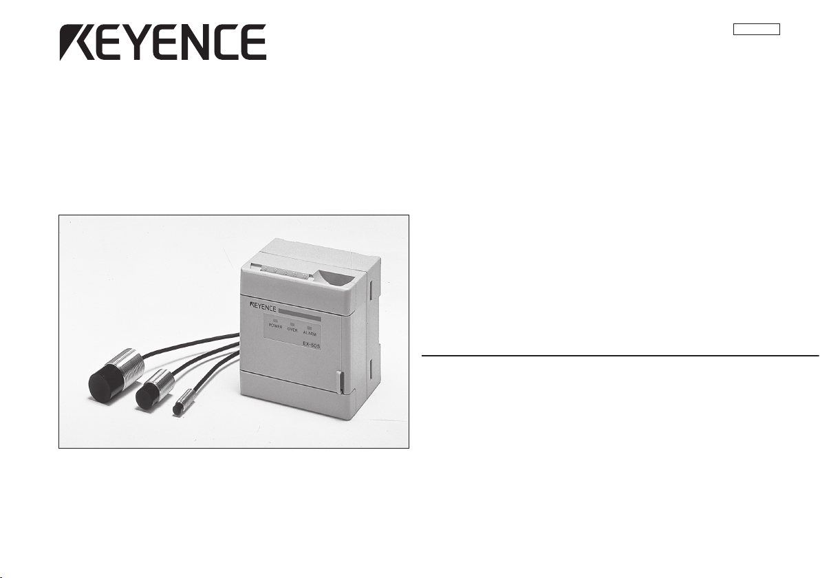
Inductive Gauging Sensor
96M0368
EX-500(W) Series
Page 2
CONTENTS
SAFETY PRECAUTIONS
Part Names and Functions.......................................................... 3
Connections ................................................................................ 4
Example of connections .............................................................. 5
Hints on correct use .................................................................... 5
Installation ................................................................................... 6
Adjustment .................................................................................. 7
Measuring range vs. analog output ............................................. 9
Auto-zero/Auto-span functions .................................................... 9
Interference suppression function ............................................. 12
Specifications ............................................................................ 13
Troubleshooting guide .............................................................. 14
Characteristics .......................................................................... 14
Dimensions ............................................................................... 15
WARRANTIES AND DISCLAIMERS ........................................ 16
Note
This is a class A (EN55011: EMI standard) product. In a domestic
environment this product may cause radio interference in which
case the user may be required to take adequate measures.
This manual describes how to install the EX-500(W) Series as well as its
operating procedures and precautions. Please read this manual carefully
to get the best from your EX-500(W) Series.
Safety precautions
Symbols
The following symbols alert you to important messages. Be sure to read
these messages carefully.
WARNING
CAUTION
Note
Failure to follow instructions may lead to injury.
(electric shock, burn, etc.)
Failure to follow instructions may lead to product
damage.
Provides additional information on proper operation.
General precautions
• At startup and during operation, be sure to monitor the functions and performance of the EX-500(W) series.
• We recommend that you take substantial safety measures to
avoid any damage in the event a problem occurs.
• Do not open or modify the EX-500(W) series or use it in any
way other than described in the specifications.
• When the EX-500(W) series is used in combination with other
instruments, functions and performance may be degraded,
depending on operating conditions and the surrounding environment.
• Do not use the EX-500(W) series for the purpose of protecting
the human body.
2
Page 3
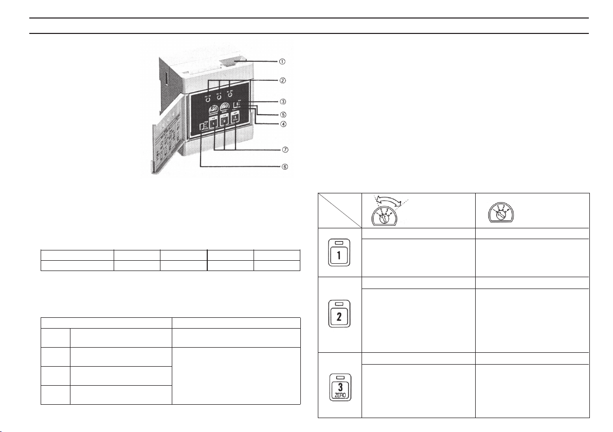
PART NAMES AND FUNCTIONS
1 Sensor head
cable connector
2 Indicators
POWER: Power indicator
OVER: Measurement out-of-range indicator
ALARM: Disconnection alarm indicator
3 Response time selector switch
You can select one of the following four response times.
RESPONSE 1 2 3 4
Response time 0.1 ms 1 ms 10 ms 100 ms
4 Mode selector switch
This switch is used to select the desired mode based on the
target material.
MODE Function
1 MEASUREMENT mode When measuring targets, set the
2 ADJUSTMENT mode
for aluminum
3 ADJUSTMENT mode
for stainless steel
4 ADJUSTMENT mode
for steel
(After completing the adjustment procedure, set the mode selector switch to "1"
to start measurements.)
switch to this position.
When adjusting output voltage
(current), select the ADJUSTMENT
mode based on the target material.
5 Cable length selector switch
Normally set this switch to "3 m" (the lower position).
When an optional extension cable (7 m) is added, set this
switch to "10 m" (the upper position). (7 m cable: model OP-
20708)
6 Lock switch
When this switch is set to LOCK (the lower position), any
output adjustment keys (7) are disabled.
7 Output adjustment keys
The functions are changed by adjusting the Mode selector
switch position.
Mode
Key No.
Zero-point set key
Sets the output to 0 V when the
target is in contact with the
sensor head.
Full-scale set key
Sets the output to 5 V when the
target is at the maximum
measuring distance from the
sensor head.
Linearity compensation key
Sets the output voltage to 2.5 V
to compensate for the linearity of
the output voltage when the
target is placed at half the
maximum measuring distance (1/
2 of F.S.) from the sensor head.
* The auto-span key functions in the range of 2 to 4 V output voltage.
ADJUSTMENT
mode
2. 3. 4
Auto-zero/Auto-span reset key
Resets the auto-zero and autospan functions.
Auto-span key
Changes the input-to-output ratio
and sets the output to 2.5 V when
the target is at any position within
measuring range.
(When current output is used,
pressing this key sets the output
current to 12 mA.)
Auto-zero key
Sets the output to 0 V when the
target is at any position within
measuring range.
(When current output is used,
pressing this key sets the output
current to 4 mA.)
MEASUREMENT
mode
1
3
Page 4
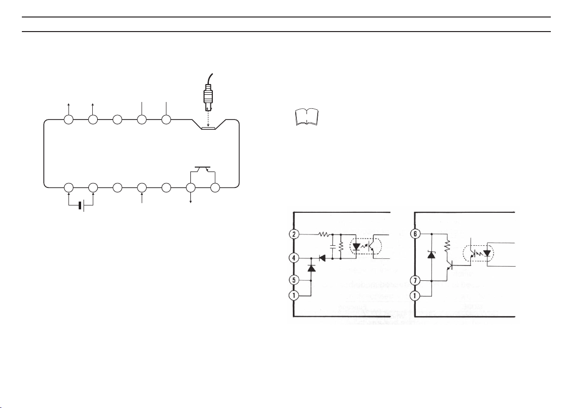
CONNECTIONS
Referring to the following descriptions of terminals, complete
connections before you turn the power ON.
Analog
voltage
output
(V)
Analog
current
output (mA)
8 9 10 11 12
1 2 3 4 5 6 7
12 to 24 VDC
Interference suppression
(CONTROL)
0 V
Auto-zero input
(SYNC)
GND
NPN output
(Disconnection alarm output)
Sensor head
cable connector
GNDNot used
4 Auto-zero input terminal:
Sets the analog output voltage to 0 V when this terminal and
GND terminal (5) are short-circuited. (When current output is
used, the output current is set to 4 mA.) (See p.9.)
6 NPN output (Disconnection alarm output) terminal:
Outputs a signal when the sensor head cable is disconnected.
8 Analog voltage output terminal:
Analog voltage of 0 to 5 V relative to full measuring range is
output.
9 Analog current output terminal:
Analog current of 4 to 20 mA relative to full measuring range is
output.
A & B Interference suppression terminals: (See p.12.)
Note
The interference suppression function is not available with the
EX-500(W) series (compliant model with the EMC directive (CE
marking)). If you want to use the function, be sure to check
whether the operation complies with the EMC directive on your
account.
Input circuit diagram Output circuit diagram
4
Page 5
CONNECTIONS
HINTS ON CORRECT USE
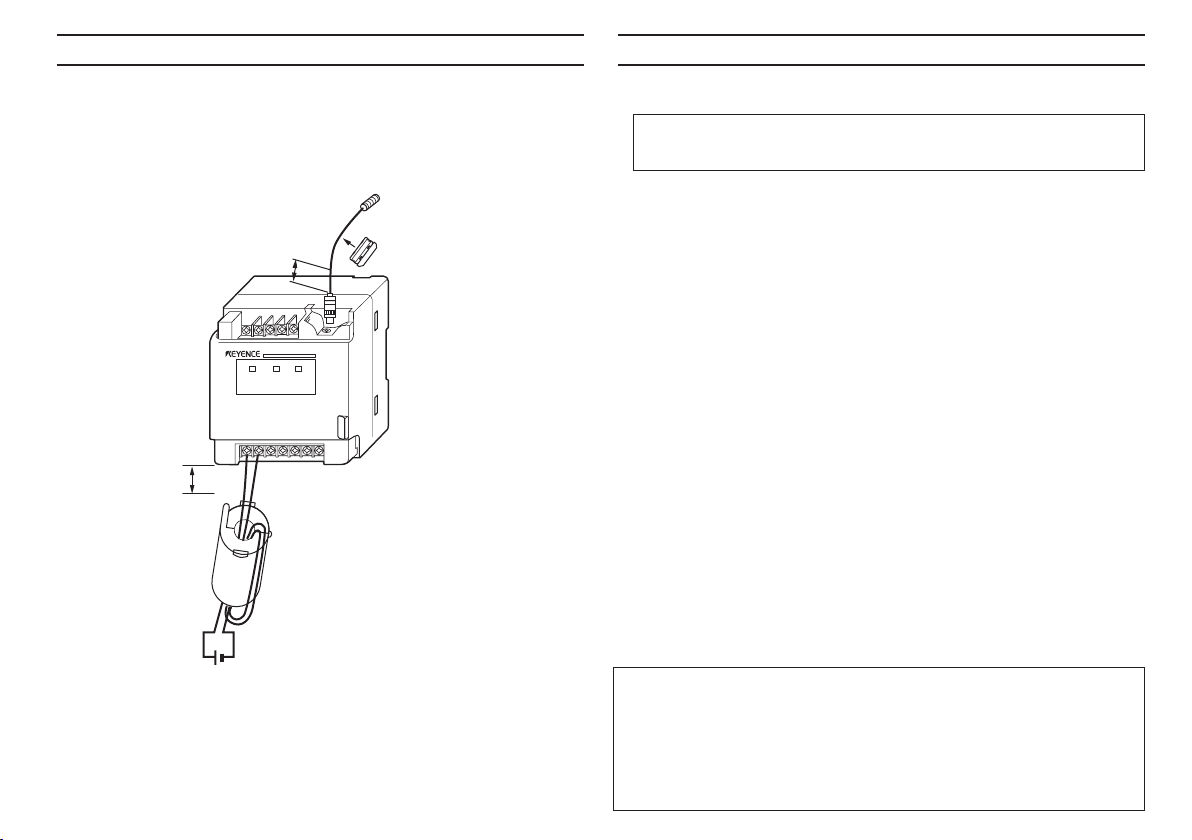
To make the EX-500(W) series comply with the EMC directive
(CE marking), use the attached ferrite cores as shown in the
illustration below.
Sensor head
Ferrite core (smaller one in
the accessory)
ZCAT1325-0530A (TDK)
30 Max.
20 Max.
8 9 10 11 12
POWER OVER ALARM
1
12 to 24 VDC
EX-501
2
3
4 5 6 7
Ferrite core (larger one in the
accessory)
ZCAT2035-0930 (TDK)
Be sure to use a sheathed cable with an
outer diameter of 2.5-mm or less for the
power cable.
■ Noise interference
When using a switching regulator, make sure that the F.G.
terminal or the GND terminal is grounded.
• Keep the wiring and connection cable away from high-voltage
lines or power lines; otherwise noise may affect the performance of the EX-500(W).
• If noise from the power supply line causes the EX-500(W) to
malfunction, use an isolating transformer with the power
supply.
■ Auto-zero input
When the DC 2-wire proximity sensor (KEYENCE EV Series) is
used for auto-zero input, power supply voltage of the EX500(W) Series must be 20 V or higher.
■ Warm-up time
Do not start adjustment/measurement until at least 30 minutes
after the power is turned ON. The circuitry is not stable during
this period and fluctuation in measured values may result.
■ Cable extension
• The standard sensor head cable length is 3 m. It can be
extended to 10 m by connecting 7-m extension cable (Model:
OP-20708).
• Do not change the specified sensor head cable length
(3 or 10 m). If you extend or cut the cable, its characteristics will change.
• The junction connector is grounded through its housing. Make necessary arrangements for insulation.
5
Page 6

INSTALLATION
Controller
The controller can be mounted to a DIN rail. When mounting or
dismounting the controller, pull the claws located at the bottom of
the controller in the direction shown by the arrows. Also, the
controller can be mounted with screws by pulling out the fittings.
When mounted on DIN rail
When mounted with screws
Sensor head
■ Connecting to/disconnecting from the controller
• Plug the sensor head cable into
the connector of the controller until
it clicks. (When connecting an
extension cable to the controller or
the sensor head, follow the same
procedure.)
• When disconnecting the plug, hold
it by the sleeve and pull it out as
shown on the right.
Incorrect
Correct
■ Mounting
Nut tightening position
3mm min
Tighten the nut away from the tip of
the metal case as shown on the right.
Torque values
Tighten the nut according to the
torque values given in the table
below.
EX-008 EX-016 EX-022
(approx. 100 kgf-cm) max. (approx. 200 kgf-cm) max. (approx. 300 kgf-cm) max.
10 Nm 20 Nm 30 Nm
■ Flush-mounting
The diagram and table below shows the dimensions to use when
flush-mounting a sensor head onto a metal plate.
øA
B
EX-008 20 11
EX-016 45 20
EX-022 60 25
A (mm) B (mm)
When connecting and disconnecting the plug, be sure to hold it by
the sleeve. If you forcefully pull on
the cable, the cable may break off
from the plug.
6
Page 7

ADJUSTMENT
Before starting measurements, adjust the analog output with
an actual target using the following procedure.
Connection
1. Connect a panel meter or voltmeter to the analog output
terminal of the controller using a shielded cable.
2. Complete the connections and then turn the power ON. The
POWER indicator of the controller lights and the sensor is in
operation mode.
* Before starting the adjustment procedure, allow the unit to
warm up for at least 30 minutes.
Setting the switches
1. Set the response time selector switch according to the required
measurement accuracy.
RESPONSE 1 2 3 4
Response time 0.1 ms 1 ms 10 ms 100 ms
RESPONSE
2. Select one of the ADJUSTMENT modes based on the target
material.
MODE
* Base material: Iron (SS41),
Plating thickness: 50 µm
Resolution 0.10% 0.06% 0.03% 0.03%
(% of F.S.)
MODE 2 3 4
Reference Aluminum Stainless steel Iron
metal (A5052) (SUS304) (S45C)
Other Copper Iron (SS41)
metals (C1100)
Brass (SUS410)
(C3560) Stainless steel
Metal- Zinc-plated Nickel-
plated* Chromium plated
-plated
Stainless steel
(SUS430)
CABLE
10 m
3 m
FREE
3. Set the cable length selector switch according to the sensor head cable length.
4. Set the lock switch to FREE (the upper
position).
■ Analog output adjustment
LOCK
1. Place the sensor head in contact with the target and press the
<1> key (zero-point set key) to check whether the output
voltage is 0 V.
The LED lights. The LED goes out.
Sensor head in
contact with target.
Hold the sensor head in contact with the target
until the LED of key <1> goes out.
Press the
<1>
key.
Approx. 3 seconds
after pressing the key.
When current output is used .
the output current is set to 4 mA.
2. Set the distance between the sensor head and the target to the
maximum measuring distance. Then press the <2> key (Fullscale set key) to check whether the output voltage is 5 V.
The LED lights.
F.S.(Max.
measuring distance)
Hold the sensor head at the maximum measuring
distance from the target until the LED of <2> key
goes out.
Press the
<2>
key.
The LED goes out.
Approx. 3 seconds
after pressing the key.
When current output is used .
the output current is set to 20 mA.
7
Page 8

ADJUSTMENT
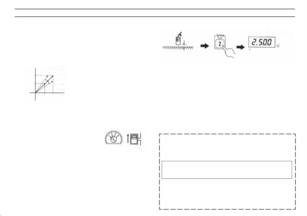
3. Set the distance between the sensor head and the target to
half the maximum measuring distance. Then press the <3> key
(linearity compensation key) to check whether the output
voltage is 2.5 V.
The LED lights.
Harf F.S.(Harf max.
measuring distance)
Hold the sensor head at half the maximum
measuring distance until the LED of <3> key
goes out.
Press the
<3>
key.
The LED goes out.
Approx. 3 seconds
after pressing the key.
When current output is used .
the output current is set to 12 mA.
• If the analog output adjustment cannot be performed during
steps (1) through (3), for example, when any key is pressed
with the target out of the measuring range, the LED of the
corresponding key flashes and the OVER indicator lights.
By pressing the flashing key, the error is reset and the LED
goes out. Re-start the adjustment procedure given in the
previous steps.
(Note: Even if an adjustment error occurs in step (3), the
linearity compensation is performed in the controller.)
• When the response time selector switch is set to RESPONSE
1 (0.1 ms), the linearity and temperature fluctuation of the
analog output voltage is not compensated to reduce the
response time. Although the output voltage is not adjusted to
exactly 2.5 V in step (3), the compensation is completed in the
controller. When a highly accurate measurement is required,
set the response time selector switch to RESPONSE 2, 3 or 4,
then you can start the measurement without re-adjusting the
output voltage.
4. Place the sensor head in contact with the target again as
described in the step (1) to check whether the output voltage is
0 V.
If the output voltage is not 0 V, repeat the steps (1) through (3).
■ Starting measurement
Set the mode selector switch to "1" (MEASUREMENT mode) to start measurement.
Mode
Precautions on analog output adjustment
• When you adjust the analog output voltage (current) using
the adjustment mode switch, be sure to complete steps (1)
through (4). If you interrupt the procedure, the linearity
compensation will not be correct.
• To be within the specifications of the EX-500(W) Series, set
the distance between the sensor head and the target exactly
as described above during the analog output adjustment.
• Making the analog output adjustment resets the auto-zero
and auto-span functions.
8
Page 9

MEASURING RANGE VS. ANALOG OUTPUT
AUTO-ZERO/AUTO-SPAN FUNCTIONS
Each sensor outputs an analog voltage (current) in proportion to the measuring distance.
EX-501(W)/008 EX-502(W)/008
Measuring range Measuring range
F.S. (Full Scale) F.S. (Full Scale)
=1 mm =2 mm
EX-505(W)/016 EX-510(W)/022
Measuring range Measuring range
F.S. (Full Scale) F.S. (Full Scale)
=5 mm =10 mm
Auto-zero function
Using the front panel key or by an external signal, the analog
output voltage can be set to 0 V (analog output current to 4 mA)
when the target is at any position within the measuring range.
This ensures quick adjustment of the output voltage (current) for a
standard target.
■ Procedure
1. The auto-zero function is activated only when the mode
selector switch is set to "1" (MEASUREMENT mode).
FREE
Mode
2. Make sure that the lock switch is set to FREE (the upper
position).
3. Place the sensor head at any position within the measurement
range. Then press the auto-zero key (or short-circuit terminal
4 and GND terminal 5 ) and check whether the output
voltage is reset to 0 V.
LOCK
The standard target is aluminum (A5052, Minimum thickness: 1 mm,
Flat plate 3 times or more larger than the sensor head diameter). When
other metals are detected, the characteristics of each sensor will
change slightly. Make the analog output adjustment using an actual
target to check the characteristics of your sensor.
9
Page 10

AUTO-ZERO/AUTO-SPAN FUNCTIONS
Example: With the EX-501(W), set the distance between the
sensor head and the target to 0.2 mm.
Press the
<3>
key.
to
Ground terminal to √ terminal ➄.
* Even when the lock switch is set to
LOCK (the lower position), the
auto-zero function can be activated
by an external signal.
When the lock switch is set to FREE, the zero-point value is stored in
the controller every time the auto-zero function is used. (The value is
retained even if the power is turned OFF.) When the lock switch is set
to LOCK, the auto-zero function can be activated by external terminal
input, but the zero-point value cannot be stored. To activate the autozero function frequently by external terminal input, set the lock switch
to LOCK.
When current output is used .
the output current is set
to 4 mA.
■ Minimum input time of external signals
ON
OFF
(Auto-zero input)
ON time
OFF
time
Response time
Input time
ON time 1 ms min. 10 ms min.
OFF time 1 ms min. 10 ms min.
RESPONSE
1 2, 3,4
■ Auto-zero process time
10
ON
OFF
(Auto-zero input)
Voltage
0 V
Process time
Response time
Lock switch
LOCK 1 ms max. 15 ms max.
FREE 40 ms max. 50 ms max.
RESPONSE
1 2, 3, 4
■ Auto-zero adjustment range
6 V
5 V
Auto-zero
adjustment range
0
-5 v
F.S.
• The output voltage can be set to 0 V when the target is at any
position within the measuring range. (When current output is
used, the output current is adjusted to 4 mA.)
• If the auto-zero key does not function; for example, if the autozero key is pressed when the sensor head is out of the measuring range, the OVER indicator lights and the LED of the autozero key flashes.
Press the auto-zero key again to reset the alarm, and then restart the procedure described above.
Even if external auto-zero input is activated when the target is out of
the measuring range, the sensor does not receive the auto-zero input
and continues measurement.
Page 11
AUTO-ZERO/AUTO-SPAN FUNCTIONS
Auto-span function
Using the auto-span function, the ratio of the analog output
voltage relative to the measuring distance can be changed. This
function is useful to measure targets having a small diameter or
round surface because with these targets the input-to-output ratio
is variable or is linear only to a limited range. Be sure to calibrate
your sensor for the desired targets.
Set desired distance
Press the
<2>
key.
When current output is used .
the output current is set
to 12 mA.
5 V
2.5 V
0
F.S.
By pressing the auto-span key, the span (inclination) of the output
voltage is automatically changed and the output voltage is set to
2.5 V. (p.16)
■ Procedure
FREE
1. The auto-span function is activated only
when the mode selector switch is set to
"1" (MEASUREMENT mode).
Mode
LOCK
2. Make sure that the lock switch is set to FREE (the upper
position).
3. Set the desired distance within the auto-span adjustment
range. Then press the auto-span key and check whether the
output voltage is set to 2.5 V.
■ Auto-span adjustment range
• The auto-span function can be activated within the range of 2
to 4 V.
(For current output, the auto-span adjustment range is 10.4 to
16.8 mA. )
• If the auto-span function cannot be activated, the OVER
indicator lights and the LED of the auto-span key flashes.
Press the auto-span key again to reset the alarm, and then restart the procedure described above.
Formula for auto-zero/auto-span
The following formula expresses the relationship between the
analog output value and the value just before the auto-zero/
auto-span function is activated.
Analog output value = Span x
(output value just before the auto-zero/
auto-span function is activated - Shift)
Resetting the auto-zero/auto-span functions
Pressing the auto-zero/auto-span reset key (<1>) resets both
functions simultaneously (when the mode selector switch is set
to MEASUREMENT mode and the lock switch is set to FREE).
11
Page 12

INTERFERENCE SUPPRESSION FUNCTION
CAUTION
EX-500W only
The terminals 0 - B for interference suppression function are
indicated as blank terminals with the EX-500W series (compliant
model with EMC directive of CE marking). These terminals can be
used for the interference suppression function as shown below.
However, please note that the EX-500W may not conform to EMC
directive, if you use this function and these terminals. If you want
to use the function, be sure to check whether the operation
complies with the EMC directive on your account.
Interference suppression function
Through a simple wiring change and using the interference
suppression function, up to 5 sensors can be installed side by
side. This enables multi-point measurement in a limited space.
■ Procedure
1. Turn the power OFF.
2. Connect wires as shown below.
Main controller
Sub controller 1
Sub controller 2
Up to 4 sub controllers
can be connected to
the main controller.
3. Make sure that the connections are completed correctly and
then turn the power ON.
Make sure that terminals 0 and A of the sub controllers are
properly connected. If you turn the power ON without connecting these terminals, the controllers may be damaged.
4. After warm-up, make the analog output adjustment under
actual measurement conditions. (See p.7)
5. Start measurement.
* Principle of operation
Using the interference suppression function of the EX-500(W)
Series, all sensors can operate at the same clock frequency.
Connect sensors using shielded cables to shorten the overall
cable length.
12
Page 13

SPECIFICATIONS
Type Threaded, non-shielded type
Size M8 M8 M16 M22
Model
Measuring range 0 to 1 mm 0 to 2 mm 0 to 5 mm 0 to 10 mm
Analog
output
Functions Response time selector function / Preset metal characteristic memory function
Temperature Sensor head 0.03% of F.S./°C
fluctuation Controller
Power supply voltage 12 to 24 VDC ±10%, Ripple (P-P): 10% max.
Current consumption 220 mA max.
Ambient
temperature
Relative humidity 35 to 85%, No condensation
Vibration 10 to 55 Hz, 1.5 mm double amplitude in X, Y and Z directions, 2 hours respectively
Enclosure rating Sensor head: IP-67
Weight
Disconnection alarm output
Sensor head EX-008 EX-008 EX-016 EX-022
Controller EX-501(W) EX-502(W) EX-505(W) EX-510(W)
Output voltage 0 to 5V
Output impedance 100 Ω
Output current 4 to 20 mA (Applicable load: 0 to 350 Ω)
Resolution 0.03 % of F.S. (RESPONSE = 3, 4)
Response time 0.1 ms (RESPONSE = 1)
(Response mode) 1 ms (RESPONSE = 2)
Linearity ±0.3 % of F.S. (RESPONSE = 2, 3, 4)
Cable length selector function / Interference suppression function
Sensor head -20 to +105°C (-4 to 221°F), No freezing
Controller 0 to +50°C (32 to 122°F), No freezing
Sensor head Approx. 50 g Approx. 50 g Approx. 63 g Approx. 80 g
Controller Approx. 360 g
10 ms (RESPONSE = 3)
100 ms (RESPONSE = 4)
Auto-zero function / Auto-span function
1.
0.04% of F.S./°C
NPN open-collector: 100 mA (40 V) max.
Residual voltage: 1 V max. (N.C.)
The above data is obtained using an aluminum target (A5052 t = 1 mm). When measuring steel or stainless steel targets, refer to the characteristics of linearity for these
materials.
1. EX-008: When the distance between the sensor head and target is half the maximum measuring distance and the operating temperature is 10 to 40°C (50 to 104°F).
EX-016, 022: When the distance between the sensor head and target is half the maximum measuring distance and the operating temperature is 0 to 50°C (32 to 122°F).
13
Page 14

TROUBLESHOOTING GUIDE
CHARACTERISTICS
If any trouble occurs with your EX-500(W) Series, check the
following items. If the sensor does not work properly, contact your
distributor or nearest KEYENCE office.
Problem
Analog output does
not change.
Analog output is not
stable.
Fluctuation in
resolution and poor
accuracy.
Key switches are
disabled.
Check items
Is the sensor head
cable tightly connected?
Is noise interference
causing problems?
Is the production line
conveyor vibrating?
Is the response time
selector switch set to
high speed?
Is the output voltage
proportional to the
measuring distance?
Is the lock switch set
to LOCK?
Remedy
Securely connect the
cable into the connector.
Keep the sensor wiring
away from high-voltage
lines and power lines.
Reduce vibration of the
production line conveyor.
If high speed response is
not required, set the
response time selector
switch to low speed.
Adjust the output voltage.
(See p.7 through 9.)
Set the lock switch to
FREE during key
operations.
■ Output voltage for measuring targets of various sizes
(Typical)
EX-502(W)/EX-008 (Target: Aluminum A5052)
• Calibrating analog output voltage
using a standard target (50 x 50 mm)
ø3 ø5 ø8 ø10 ø16
5
Voltage (V)
Distance
0
Measuring distance (mm)
2.0
ø(mm)
• Calibrating analog output voltage using
target of various sizes (diameter)
5
Voltage (V)
0
ø3
ø5
ø8
ø10
Measuring distance (mm)
2.0
ø(mm)
■ Linearity for various metal measurement (Typical)
EX-502(W)/EX-008
Aluminum (Adjustment mode 2)
0.3
Aluminum (A5052)
0
Copper (Cu1100)
-0.3 -0.3
Linearity (% of F.S.)
0 2.0
Iron (Adjustment mode 4)
Measuring distance (mm)
Stainless steel (Adjustment mode 3)
0.3
0
Linearity (% of F.S.)
0 2.0
Stainless steel (SUS304)
1.01.0
Measuring distance (mm)
Distance
14
0.3
0
-0.3
Linearity (% of F.S.)
0 2.0
Iron (S45C)
Iron (SS41)
1.0
Measuring distance (mm)
Page 15

DIMENSIONS
Controller EX-5xx(W) Sensor head
EX-008
ø6.5
M8, P=1
112
136.5
100 90
0 to 180°
60
85
4 x ø5
(mounting
hole)
35.4
652.5
EX-016
ø14
M16, P=1
EX-022
ø20.5
M22, P=1
Expansion cable (OP-20708)
10.4
15.6
20 185.2
Across flats: 12, t = 3
21
25
25
Unit: mm
ø6.4
ø2.8, Cable length: 3 m
18
ø6.4
ø2.8, Cable length: 3 m
Across flats: 21, t = 4
18
ø6.4
ø2.8, Cable length: 3 m
Across flats: 30, t = 4
18
ø6.4
ø2.8, Cable length: 7 m
ø6.4
15
Page 16
WARRANTIES AND DISCLAIMERS
(1) KEYENCE warrants the Products to be free of defects in materials and workmanship for a period of one (1) year from the date of shipment. If any models or samples were shown to
Buyer, such models or samples were used merely to illustrate the general type and quality of the Products and not to represent that the Products would necessarily conform to said models
or samples. Any Products found to be defective must be shipped to KEYENCE with all shipping costs paid by Buyer or offered to KEYENCE for inspection and examination. Upon
examination by KEYENCE, KEYENCE, at its sole option, will refund the purchase price of, or repair or replace at no charge any Products found to be defective. This warranty does not
apply to any defects resulting from any action of Buyer, including but not limited to improper installation, improper interfacing, improper repair, unauthorized modification, misapplication and
mishandling, such as exposure to excessive current, heat, coldness, moisture, vibration or outdoors air. Components which wear are not warranted.
(2) KEYENCE is pleased to offer suggestions on the use of its various Products. They are only suggestions, and it is Buyer’s responsibility to ascertain the fitness of the Products for
Buyer’s intended use. KEYENCE will not be responsible for any damages that may result from the use of the Products.
(3) The Products and any samples (“Products/Samples”) supplied to Buyer are not to be used internally in humans, for human transportation, as safety devices or fail-safe systems,
unless their written specifications state otherwise. Should any Products/Samples be used in such a manner or misused in any way, KEYENCE assumes no responsibility, and additionally
Buyer will indemnify KEYENCE and hold KEYENCE harmless from any liability or damage whatsoever arising out of any misuse of the Products/Samples.
(4) OTHER THAN AS STATED HEREIN, THE PRODUCTS/SAMPLES ARE PROVIDED WITH NO OTHER WARRANTIES WHATSOEVER. ALL EXPRESS, IMPLIED, AND STATUTORY WARRANTIES, INCLUDING, WITHOUT LIMITATION, THE WARRANTIES OF MERCHANTABILITY, FITNESS FOR A PARTICULAR PURPOSE, AND NON-INFRINGEMENT OF
PROPRIETARY RIGHTS, ARE EXPRESSLY DISCLAIMED. IN NO EVENT SHALL KEYENCE AND ITS AFFILIATED ENTITIES BE LIABLE TO ANY PERSON OR ENTITY FOR ANY
DIRECT, INDIRECT, INCIDENTAL, PUNITIVE, SPECIAL OR CONSEQUENTIAL DAMAGES (INCLUDING, WITHOUT LIMITATION, ANY DAMAGES RESULTING FROM LOSS OF USE,
BUSINESS INTERRUPTION, LOSS OF INFORMATION, LOSS OR INACCURACY OF DATA, LOSS OF PROFITS, LOSS OF SAVINGS, THE COST OF PROCUREMENT OF SUBSTITUTED GOODS, SERVICES OR TECHNOLOGIES, OR FOR ANY MATTER ARISING OUT OF OR IN CONNECTION WITH THE USE OR INABILITY TO USE THE PRODUCTS, EVEN IF
KEYENCE OR ONE OF ITS AFFILIATED ENTITIES WAS ADVISED OF A POSSIBLE THIRD PARTY’S CLAIM FOR DAMAGES OR ANY OTHER CLAIM AGAINST BUYER. In some
jurisdictions, some of the foregoing warranty disclaimers or damage limitations may not apply.
BUYER’S TRANSFER OBLIGATIONS: If the Products/Samples purchased by Buyer are to be resold or delivered to a third party, Buyer must provide such third party with a copy of this
document, all specifications, manuals, catalogs, leaflets and written information provided to Buyer pertaining to the Products/Samples.
16
Copyright (c) 1993 KEYENCE CORPORATION. All rights reserved. 0072E 1080-2 96M0368 Printed in Japan
Copyright (c) 1993 KEYENCE CORPORATION. All rights reserved. 0072E 1093-2a 96M0368 Printed in Japan
 Loading...