

Page 1
RS-232C Communication Unit
DL-RS1A
Instruction Manual
96M00489
● Proper environment and conditions
To use the DL-RS1A properly and safely, do not install the DL-RS1A in
locations with the following conditions. Use of this equipment in an
improper environment may cause equipment failure.
• Locations with high humidity, a large amount of dust, or poor ventilation
• Locations where the temperature rises excessively due to direct
sunlight, etc.
• Locations where corrosive or flammable gas exists
• Locations where the DL-RS1A is directly subjected to vibration or
impact
• Locations where water, oil or chemicals may splash the DL-RS1A
• Locations where static electricity is easily built up
● Noise countermeasures
Installation near a source of noise such as a power source or power cable
may cause a malfunction or failure in the equipment. Adopt appropriate
countermeasures against noise by using a noise filter or wiring cables in
separate ducts, attaching insulation to the sensor amplifier or the sensor
head, etc.
Package Contents
Safety Precautions
■ General Cautions
• At startup and during operation, be sure to monitor the functions and
performance of the DL-RS1A.
• Provide appropriate safety measures to avoid any damage in the event that
a problem occurs.
• Do not modify the DL-RS1A or use it in any way other than described in the
specifications. The functions and performance of products used or
modified in this way cannot be assured.
• When the DL-RS1A is used in combination with other instruments, its
functions and performance may be degraded, depending on the operating
conditions and surrounding environment. Use the DL-RS1A after fully
studying the effects of combined use with other instruments.
• Do not use the DL-RS1A for the purpose of protecting the human body.
•
Do not expose the DL-RS1A and peripheral devices to sudden
temperature changes. This may cause condensation, damaging the
equipment.
If the following conditions are encountered,
immediately turn off the power. Continuing to use the
DL-RS1A under abnormal conditions may cause fire,
WARNING
WARNING
electric shock or equipment failure.
• When water or foreign matter enters the controller
• When the DL-RS1A is dropped or the housing is
damaged
• When the DL-RS1A produces smoke or an abnormal
smell
• Do not use the DL-RS1A with a voltage other than
specified voltage, as this may cause fire, electric
shock or equipment failure.
• Do not disassemble or modify the DL-RS1A. This
may cause fire or electric shock.
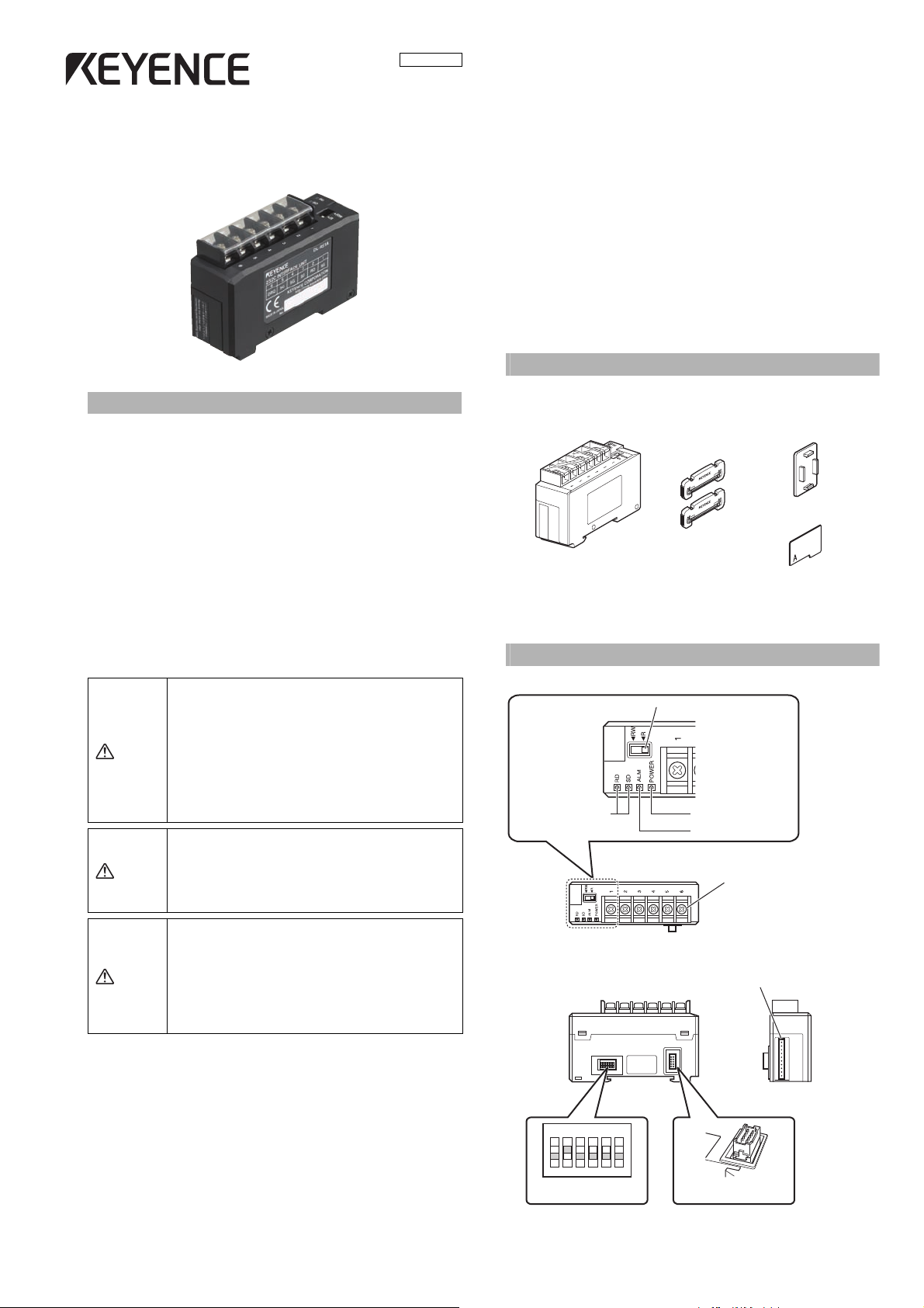
The product package should include the following items. Check that all items
are included before use.
Expansion connector cover
RS-232C Communication unit
DL-RS1A
All possible care was taken in packaging; however, if any parts are found to
be defective or broken, please contact your nearest KEYENCE sales office.
End unit x 2
OP-26751
Switch protection sticker
Parts Names
Read/write setting switch
Communication status
indicator (green)
Power indicator (green)
Alarm indicator (red)
Communication
terminal block
CAUTION
• Be sure to turn off the power to the DL-RS1A and
any connected devices before connecting or
disconnecting the cables. Otherwise, there may be a
risk of damaging the unit.
• Do not turn off the power while setting a parameter.
Otherwise, the settings may be partially or
completely lost.
Sensor amplifier connector
(for panel mounting type / large display type)*
D
G
102#345
6
*Sticker is attached.
10
2N345
Communication setting switch
6
Sensor amplifier connector
(for DIN rail mounting type)
1
Page 2
Mounting and connecting
(1)
(3)
(2)
Note
Sensor amplifier
Expansion protective cover
Sensor amplifier
RS-232C Communication unit
DL-RS1A
Connector
Sensor amplifier connector
RS-232C Communication Unit DL-RS1A
End unit
End unit
Detach the protection sticker
Expansion cable (cable length: 300mm)
Detach the
protection
sticker
Expansion cable (cable length: 300mm)
Detach the
protection sticker
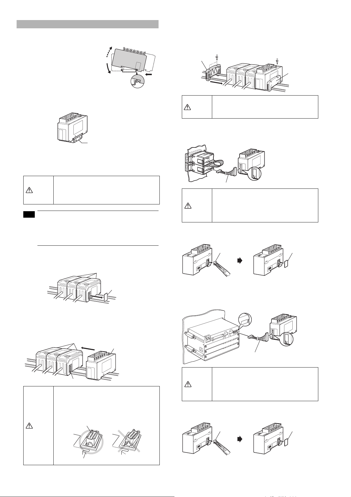
■ Mounting on the a DIN rail
1 Fit the tab of the lower part of the main
unit to the DIN rail. While inserting the
main unit in the direction of arrow 1,
push the body in the direction of arrow
2.
2 To detach the main unit, while pushing
the main unit in the direction of arrow
1, pull the body in the direction of
arrow 3.
When using a fixture (OP-60412), mount the main unit as shown below.
Fixture: OP-60412
■ How to connect to the sensor amplifier
The RS-232C Communication Unit DL-RS1A is used by connecting it to a
sensor amplifier. The connection method varies according to the mounting
type of the sensor amplifier to connect to.
When connecting the RS-232C Communication Unit
DL-RS1A, be sure to check the power of sensor
CAUTION
●
Connecting to a DIN rail mounting type sensor amplifier
amplifier is OFF before performing the operation.
Performing the operation when the power of sensor
amplifier is ON may damage the equipment.
• Refer to the "RS-232C Communication Unit DL-RS1A
Users' Manual" (page 9) for details about the
connectable sensor amplifiers.
• Refer to the Instruction Manual of each sensor
amplifier for details about how to add the sensor
amplifier.
1 Detach the expansion protective cover of the sensor amplifier to
which the communication unit is to be connected.
3 Mount the end units (OP-26751: a set of two pieces) on both sides of
the sensor amplifier and the RS-232C Communication Unit DL-RS1A,
then fix the end units with screws on the upper part of each end unit
(2 points x 2 units).
The mounting method of the end unit is the same as that of the
Communication Unit DL-RS1A.
Be sure to insert the RS-232C Communication Unit
CAUTION
DL-RS1A to the sensor amplifier at the end. Turning
on the power with diagonal insertion or improper
insertion may damage the equipment.
RS-232C
● Connecting to a panel mounting type sensor amplifier
1
Connect the sensor amplifier to the RS-232C Communication Unit DLRS1A using the optional expansion cable (OP-35361).
• Turn OFF the power before connecting the
expansion cable and connect securely. Diagonal
CAUTION
or otherwise improper insertion may damage the
equipment.
• Inserting or pulling the cable when the power is
turned ON may damage the equipment.
2 Detach the sensor amplifier connector (DIN rail mounting type) of the
RS-232C Communication Unit DL-RS1A with pliers and mount the
attached expansion connector.
Sensor amplifier connector
(for DIN rail mounting type)
Expansion
connector cover
2 Mount the RS-232C Communication Unit DL-RS1A on the DIN rail
and connect it to the sensor amplifier.
Push and fix the RS-232C Communication Unit DL-RS1A to make
sure there is no space between the communication unit and the
sensor amplifier.
Refer to the figure below, and check that the sensor
amplifier connector (for DIN rail mounting type) on
the side of the RS-232C Communication Unit DLRS1A is not mounted at an angle. Connecting to the
sensor amplifier with the connector diagonally may
damage the equipment.
CAUTION
● Connecting to a large display type sensor amplifier
1
Connect the sensor amplifier to the RS-232C Communication Unit DLRS1A using the optional expansion cable (OP-35361).
• Turn OFF the power before connecting the
expansion cable and connect securely. Diagonal
CAUTION
or otherwise improper insertion may damage the
equipment.
• Inserting or pulling the cable when the power is
turned ON may damage the equipment.
2 Detach the sensor amplifier connector (DIN rail mounting type) of the
RS-232C Communication Unit DL-RS1A with pliers and mount the
attached expansion connector.
Sensor amplifier connector
(for DIN rail mounting type)
2
Expansion
connector cover
Page 3

Connecting to an External Device
KPEV-SP(1P) wire with balanced
type twisted shield (strand wire)
SG
RD
SD
SG
SG
DRQ
Communication cable
OP-81283
To an external device
Note
B
B
φd
d
Note
(Short-circuit current 1mA max.)
6(DRQ)
+5V
1,4,5(SG)*
Main circuit
10
0
N
23456
6
10
2N345
6
Communication setting switch
Note
ON
4
ON
4
8bit * 7bit
Note
■ Connection
* Recommended communication cable:
KPEV-SP(1P) wire with balanced type twisted shield (strand wire)
Nominal cross-section area 0.16mm
Terminal No. Terminal symbol Description
1SG
2 RD (input)
3 SD (output)
4 SG Terminals 1, 4 and 5 are internally connected.
5 SG Terminals 1, 4 and 5 are internally connected.
6 DRQ (input)
2
(AWG25) min.
Connect the shield wire of the communication
cable. Terminals 1, 4 and 5 are internally
connected.
Connect to SD of an external device with the
communication cable.
Connect to RD of an external device with the
communication cable.
If terminals 6 (DRQ) and terminals 1, 4 or 5 (SG)
are short circuited, data is transmitted without a
command from an external device.
■ Input circuit diagram
* Pin No. 1, 4 and 5 (SG) are common to the 0V blue wire on the main
sensor amplifier.
Communication Settings
Use the communication setting switch for communication settings.
Switch No.
Setting item Combination
1
2400bit/s 4800bit/s 9600bit/s*19200bit/s 38400bit/s
ON
ON ON
ON
ON
A terminal cover is attached to the terminal block. After
performing the wiring, be sure to reattach the terminal cover.
● Crimp-type terminal
Use Y or round terminals for wiring to the I/O terminal of the following sizes.
Y terminal
Excerpted from dimensions of the Y terminal areas
B: Outer size of Y area
d: Width of inner
Applicable dimension
B: 6mm max.
d: 3.2mm min.
Y area (joint area with screw)
Round terminal
Excerpted from dimensions of the round terminal areas
B: Outer size of round area
d: Diameter of inner round area
Applicable dimension
B: 6mm max.
d: 3.2mm min.
(joint area with screw)
■ Wiring
To connect to an external device including a PC,
refer to the following wiring diagram for connection.
RS-232C Communication unit
DL-RS1A
1
SG
2
RD
3
SD
4
SG
5
SG
6
DRQ
Shield
External connecting
device (including a PC)
RD
SD
DR
ER
RS
CS
SG
Communication
2
speed
3
4 Data bit length
123 123 123 123 123
*Settings before shipment.
*Settings before shipment.
5
Parity check
6
None * Even Odd None
ON
56
*Settings before shipment.
• After changing the
communication settings, be
sure to cycle power.
• After setting, reattach the
included switch protection
sticker.
Do not use the switches No.1 to 3
in combinations other than those
shown above.
ON
56ON56
ON
56
Switch protection sticker
• The cable to be used for communication should be
15m or less.
• Be sure to connect the shield wire of the shield cable
to the SG terminal on the external device.
• The shield wire connected to SG terminal should not
contact with other signal cables or terminal blocks.
3
Page 4

Specifications
22.5
(48.2)
43.8
37.2
21.1 35.4
70
Unit: mm
2-(4.4×3.4)
5
37.2
43.8
51.3
31.4
70
15
15
28.5
35.5
22.5
2-φ3.4
Unit: mm
Copyright (c) 2008 KEYENCE CORPORATION. All rights reser ved. 0128-1 96M00489 Printed in Japan
Warranty
■ Main unit
Model DL-RS1A
Supply voltage
Current consumption 25 mA max.
Number of connectable sensor
amplifiers
Indicator
Environmental
resistance
Material Main unit cover: Polycarbonate
Weight Approx. 53 g
Accessory
* The number of connectable sensor amplifiers varies depending on the
Item Specification
20 to 30 VDC, including 10% ripple (P-P). Class2
(supplied from the connected sensor amplifier)
Varies depending on the model*
Communication status indicator (green x 2),
Alarm indicator (red), Power indicator (green)
Ambient
temperature
Relative
humidity
Vibration
-10 to +55°C (No freezing)
35 to 85%RH (No condensation)
10 to 55 Hz, Horizontal amplitude: 1.5 mm, 2
hours each in X, Y, and Z axis
Instruction Manual, End unit x 2, Expansion
connector cover, Switch protection sticker
model to be connected.
• When configured with the GT2-70 Series units:
Up to 15 units (including the master unit)
• GT2-100 Series:
One unit (by connecting the head expansion boards, up to 11
sensor heads can be connected to one amplifier.)
• When configured with the GT-70A Series/FD-MA Series units:
Up to 10 units (including the master unit)
(When multiple models are included, the maximum number of
connectable units is limited to that of the model with the least
number of connectable units.)
• FD-S Series: Up to 4 units (including the main unit). (Use the FD-S
Series independently without mixing other models.)
■ Communication
Item Specification
Communication type Full duplex
Synchronization type Asynchronous
Transmission code ASCII
Communication speed
Data bit length
Parity check Select from none, even and odd (Before shipment: none)
Stop bit length 1 bit
Data separator
Select from 2400, 4800, 9600, 19200, 38400 (Before
shipment: 9600 bit/s)
Select either 8 bits or 7 bits (Before shipment: 8 bits)
At reception: Automatically recognizes CR or CR+LF
At transmission: fixed to CR+LF
KEYENCE warrants its Products to be free from defects of material and
workmanship and will, without charge, replace or repair (at KEYENCE's sole
option) any Products found defective upon inspection at its factory, or other
designated point provided the equipment has been returned, transportation
prepaid, within one year from the date of shipment. Warranty is specifically at
the factory. Any on-site service will be provided at the sole expense of the
Purchaser at standard field service rates. All associated equipment must be
protected by properly rated electronic/electrical protection devices.
KEYENCE shall not be liable for any damage due to improper engineering,
installation, interfacing, use, modification or any action not in accordance with
this instruction manual. Proper installation, operation and maintenance of the
product in accordance with this instruction manual become the responsibility
of the user upon receipt of the Product. The user shall indemnify KEYENCE
and hold KEYENCE harmless from any liability or damage whatsoever arising
out of any action not in accordance with this instruction manual. Components
which wear are not warranted.
OTHER THAN AS STATED HEREIN, THE PRODUCTS ARE PROVIDED WITH
NO OTHER WARRANTIES WHATSOEVER.
ALL EXPRESS, IMPLIED, AND STATUTORY WARRANTIES, INCLUDING,
WITHOUT LIMITATION, THE WARRANTIES OF MERCHANTABILITY, FITNESS
FOR A PARTICULAR PURPOSE, AND NON-INFRINGEMENT OF
PROPRIETARY RIGHTS, ARE EXPRESSLY DISCLAIMED. IN NO EVENT
SHALL KEYENCE AND ITS AFFILIATED ENTITIES BE LIABLE TO ANY
PERSON OR ENTITY FOR ANY DIRECT, INDIRECT, INCIDENTAL, PUNITIVE,
SPECIAL OR CONSEQUENTIAL DAMAGES (INCLUDING, WITHOUT
LIMITATION, ANY DAMAGES RESULTING FROM LOSS OF USE, BUSINESS
INTERRUPTION, LOSS OF INFORMATION, LOSS OR INACCURACY OF
DATA, LOSS OF PROFITS, LOSS OF SAVINGS, THE COST OF
PROCUREMENT OF SUBSTITUTED GOODS, SERVICES OR
TECHNOLOGIES, OR FOR ANY MATTER ARISING OUT OF OR IN
CONNECTION WITH THE USE OR INABILITY TO USE THE PRODUCTS,
EVEN IF KEYENCE OR ONE OF ITS AFFILIATED ENTITIES WAS ADVISED OF
A POSSIBLE THIRD PARTY'S CLAIM FOR DAMAGES OR ANY OTHER CLAIM
AGAINST THE PURCHASER. No representation or warranty, express or
implied, made by any sales representative, distributor, or other agent or
representative of KEYENCE which is not specifically set forth herein shall be
binding upon KEYENCE. In some jurisdictions, some of the foregoing
warranty disclaimers or damage limitations may not apply.
Dimensions
■ When mounting on a DIN rail
■ When using an optional fixture (OP-60412)
4
 Loading...