

Page 1

410GB
Read this manual before using the system in order to
achieve maximum performance.
Keep this manual in a safe place for future reference.
BCD Output Unit
User's Manual
DL-RB1A
Page 2

Introduction
Important
Note
Reference
This manual provides an overview of the BCD output unit DL-RB1A and describes the functions and
procedures of the unit.
Be sure to read this manual carefully to ensure safe performance and function of the unit.
Keep this manual in a safe place for future reference.
Symbols
The following symbols alert you to important messages. Be sure to read these messages carefully.
WAR NING
CAUTION
Failure to follow instruction may lead to product damage.
Indicates an important operating procedure that could be easily mistaken.
Provides advanced and useful information for operation.
Failure to follow instructions may lead to physical.
(electric shock, burn, etc.)
Indicates the cautions and restrictions that are necessary for proper
operation.
Page 3

Safety Precautions
General Cautions
• At startup and during operation, be sure to monitor the functions and performance of the DL-RB1A for proper
operations.
• It is recommended that you take substantial safety measures to avoid any damage in the event that a problem
occurs.
• Do not modify the DL-RB1A or use it in any way other than described in the specifications.
• When the DL-RB1A is used in combination with other instruments, functions and performance may be degraded,
depending on the operating conditions and surrounding environment.
• Do not use the DL-RB1A for the purpose of protecting the human body.
• Do not change the temperature drastically around the DL-RB1A and other devices, including the accessories,
otherwise condensation may be generated.
Handling Errors
Turn off the power immediately in the following cases. Using the unit under
abnormal conditions could cause fire, electric shock, or malfunction.
WARNING
Operating Precautions
If fluid including water, chemicals, or debris enter the unit
If the unit is dropped or the case is damaged
If abnormal smoke or odor is present
Contact the nearest KEYENCE office for repair
WARNING
CAUTION
Do not disassemble or modify the DL-RB1A. Doing so may cause fire or
electric shock.
Be sure to turn off the power to the DL-RB1A and any connected devices
before connecting or disconnecting the cables. Failure to do so may
damage the unit.
Do not turn off the power while setting a parameter. Otherwise, the settings
may be partially or completely lost.
410GB
1
Page 4

Installation environment
To use the DL-RB1A correctly and safely, avoid installing it in the following locations. Failure to do so
may cause fire, electric shock, and malfunction.
• Locations that are humid, dusty, or poorly ventilated
• Locations with a high temperature, such as a place exposed to direct sunlight
• Locations where there are flammable or corrosive gases
• Location where the unit may be directly subjected to vibration or impact
• Locations where water, oil, or chemicals may splash onto the unit.
• Locations where static electricity is easily generated
Noise countermeasures
Isolate the unit from devices that generate high frequency, power supply lines, or power lines.
Otherwise, noise could cause a malfunction or accident.
2
Page 5

Contents
Safety Precautions ............................................................................................................... 1
General Cautions ............................................................................................................. 1
Handling Errors ................................................................................................................1
Operating Precautions ..................................................................................................... 1
Installation environment ................................................................................................... 2
Noise countermeasures ................................................................................................... 2
Chapter 1 Introduction
1-1 Before Using the Unit....................................................................................... 6
Checking the Package Contents ..................................................................................... 6
Part Names and Functions............................................................................................... 6
Chapter 2 Mounting and Connecting the DL-RB1A
2-1 Connecting the Unit to Sensor Amplifiers................................................... 10
Mounting the Unit ........................................................................................................... 10
Mounting the unit on a DIN rail....................................................................................... 10
Connecting the Unit to Sensor Amplifiers ......................................................................10
Available sensor amplifiers ............................................................................................ 11
Data that can be output ................................................................................................. 12
Connecting the DL-RB1A to DIN rail mounted sensor amplifiers .................................. 13
Connecting the DL-RB1A to panel mounted sensor amplifiers ..................................... 14
Connecting to a large display type sensor amplifier ..................................................... 14
2-2 Connecting the DL-RB1A to External Devices ............................................ 15
I/O Connector................................................................................................................. 15
Input circuit diagram ...................................................................................................... 18
Combining and Wiring Connectors................................................................................ 19
Connectors..................................................................................................................... 19
Precautions when wiring (OP-23139 and OP-42224) .................................................... 20
Dedicated crimping tool................................................................................................. 21
Wiring to the connector ..................................................................................................21
Chapter 3 Advanced Functions
3-1 Data Processing and Operation Modes ....................................................... 24
Sensor Amplifier ID Number Assignments..................................................................... 24
DIN rail mounted sensor amplifiers ................................................................................ 24
Panel mounted sensor amplifiers................................................................................... 24
Large display type sensor amplifiers (GT2-100N/100P)................................................ 25
Communication Unit Data Update Time ........................................................................ 26
Time chart ......................................................................................................................26
Operation Modes ........................................................................................................... 27
OUT mode...................................................................................................................... 27
OR mode ........................................................................................................................ 28
TIMER mode................................................................................................................... 30
3
Page 6

Chapter 4 Appendix
4-1 Specifications................................................................................................. 32
Performance specifications............................................................................................ 32
Dimensions..................................................................................................................... 33
When the unit is mounted on a DIN rail.......................................................................... 33
When the optional mounting bracket (OP-60412) is used ............................................. 33
Index .......................................................................................................................... 35
4
Page 7

1
1
Introduction
Introduction
This chapter describes the information you need to
know before you start using the DL-RB1A, such as the
package contents and part names.
1-1 Before Using the Unit . . . . . . . . . . . . . . . . . . . . . . . . . . 6
5
Page 8

1
1-1 Before Using the Unit
End units (x2)
OP-26751
BCD output unit
DL-RB1A
expansion connector cover
Switch protection sticker
1
BCD Output Unit
DL-RB1A
Instruction Manual
Safety Precautions
■
General Cautions
•At startup and during operation, be sure to monitor the functions and
performance of the DL-RB1A.
•Provide appropriate safety measures to avoid any damage in the event
that a problem occurs.
•Do not modify the DL-RB1A or use it in any way other than described in
the specifications. The functions and performance of products used or
modified in this way cannot be assured.
•When the DL-RB1A is used in combination with other instruments, its
functions and performance may be degraded, depending on the operating
conditions and surrounding environment. Use the DL-RB1A after fully
studying the effect of combined use with other instruments.
•Do not use the DL-RB1A for the purpose of protecting the human body.
•Do not expose the DL-RB1A and peripheral devices to sudden
temperature changes. This may cause condensation, damaging the
equipment.
z
Proper environment and conditions
To use the DL-RB1A properly and safely, do not install the DL-RB1A
in locations with the following conditions. Use of this equipment in
an improper environment may cause equipment failure.
•
Locations with high humidity, a large amount of dust, or poor ventilation
•
Locations where the temperature rises excessively due to direct
sunlight, etc.
•
Locations where corrosive or flammable gas exists
•
Locations where the DL-RB1A is directly subjected to vibration or
impact
•
Locations where water, oil or chemicals may splash the DL-RB1A
•
Locations where static electricity is easily built up
z
Noise countermeasures
Installation near a source of noise such as a power source and a
power cable may cause a malfunction or failure in the equipment.
Adopt appropriate countermeasures against noise by using a noise
filter or wiring cables in separate ducts, attaching insulation to the
sensor amplifier or the sensor head, etc.
Package Contents
The product package should include the following items. Check that all
items are included before use.
We made all possible cares in packaging; however, if any parts are found to
be defective or broken, please contact your nearest KEYENCE sales office.
Parts Names
WARNING
If the following conditions are encountered,
immediately turn off the power. Continuing to use
the DL-RB1A under abnormal conditions may
cause fire, electric shock or equipment failure.
•When water or foreign matter enters the
controller
•When the DL-RB1A is dropped or the housing
is damaged
•When the DL-RB1A produces smoke or an abnormal
smell
WARNING
•Do not use the DL-RB1A with a voltage other
than specified voltage, as this may cause fire,
electric shock or equipment failure.
•Do not disassemble or modify the DL-RB1A.
This may cause fire or electric shock.
CAUTION
•Be sure to turn off the power to the DL-RB1A
and any connected devices before connecting
or disconnecting the cables. Otherwise, there
may be a risk of damaging the unit.
•Do not turn off the power while setting a
parameter. Otherwise, the settings may be
partially or completely lost.
End unit x 2
OP-26751
Communication unit
DL-RB1A
Expansion connector cover
Switch protect sticker
Alarm indicator (red)
Power indicator (green)
Connector terminal area
Sensor amplifier connector
(for panel mounting type)*
I/O connector
Sensor amplifier connector
(for DIN rail mounting type)
*Sticker is attached.
Advanced setting switch
102#345
6
G
D
24 6 81012141618 20 22 24 26 28 30 32 34
135 7 9111315171921232527293133
10
2N345
6
96M00248
Instruction manual
Connector terminals
(6) I/O connector
(1) Advanced setting
switches
(2)
Sensor amplifier connector
(for DIN rail mounting)
(3) Sensor amplifier connector
102#345
6
G
D
10
2N345
6
2 4 6 8 10 12 14 16 18 20 22 24 26 28 30 32 34
13579111315171921232527293133
(for panel mounting type/
large display type)*
(4) Alarm indicator (red)
(5) Power indicator
(green)
Introduction
Checking the Package Contents
Before using the DL-RB1A, check that the following items are all included.
We have thoroughly inspected the package contents before shipment. However, in the event of
defective or broken items, please contact your nearest KEYENCE office.
Part Names and Functions
6
Page 9

1
(1) Advanced setting switches
ON
1
ON
1
Negative logic*
Positive logic
Note
ON ONON
ON
456
ON ONON
ON
456 456 456
456 456 456 456
1ms*2ms 4ms 8ms
16ms 32ms 64ms 128ms
Note
You can use different ON/OFF combinations to configure the output settings.
Switch No. Setting item Combination
Setting enabled only for BCD output (Pin Nos. 6 to 29) and
BCD polarity code output (Pin No. 30).
1Output logic
* Factory default positions are shown.
1-1 Before Using the Unit
Introduction
2
3
4
5
6
• Make sure you cycle the power to the unit after modifying
the settings. The modifications are not applied to the unit
until it is powered down and power has been reapplied.
• Place the switch protection sticker supplied with the unit
over the switches after you modify the settings.
BCD data
output method
BCD output update
cycle time in the
TIMER mode
Negative logic: The bit for each BCD output will be 1 when the
BCD output (Pin Nos. 6 to 30) is on.
Positive logic: The bit for each BCD output will be 1 when the
BCD output (Pin Nos. 6 to 30) is off.
Set the method for handling all outputs except for the alarm
output (Pin Nos. 6 to 31).
OUT mode* OR mode TIMER mode
ON
23ON23ON23
* Factory default positions are shown.
Do not use combinations other than those shown above for
switch numbers 2 and 3.
* Factory default positions are shown.
Switch protection sticker
7
Page 10

1
1-1 Before Using the Unit
Note
(2) Sensor amplifier connector (for DIN rail mounting type)
Introduction
Use this connector to connect DL-RB1A to the sensor amplifier that is mounted on a DIN rail.
(3) Sensor amplifier connector (for panel mounting/large display type)
Use this connector to connect DL-RB1A to a sensor amplifier for panel mounting/large display.
The optional extension cable (OP-35361) must be used for connection.
You cannot connect DL-RB1A simultaneously to a DIN rail mounted sensor amplifier and a
panel mounted sensor amplifier.
(4) Alarm indicator
The alarm indicator is lit during the following conditions.
• Immediately after turning on the DL-RB1A
*1
• When updating the BCD output, if the selected ID number for the sensor amplifier does not exist
• When updating the BCD output, if there is an error with the selected ID number for the sensor
amplifier
• When there is overcurrent on one of the outputs (Pin Nos. 6 to 32)
• Until the initialization is completed if the main unit (ID: 00) is initialized while it is connected to the
GT2-100N/100P.
*1 After turning on the power, the alarm indicator lights up for the following amount of time, and BCD
output cannot be performed during this time. (“+EEEEEE” is output during this time.)
No. of connected units Incommunicable time
1 to 5 Approx. 2 s
6 to 10 Approx. 4 s
11 to 15 Approx. 6 s
*2 The alarm indicator flashes.
*2
(5) Power indicator
Lights up in green while the power is on.
(6) I/O connector
Connector for data input and output.
For information about each signal on the connector, refer to "I/O Connector" (page 15).
8
Page 11

2
2
Mounting and Connecting the DL-RB1A
Mounting and Connecting the
DL-RB1A
This chapter describes how to mount DL-RB1A, connect it to sensor
amplifiers or external devices, and wire the I/O connector.
2-1 Connecting the Unit to Sensor Amplifiers . . . . . . . . . . 10
2-1 Connecting the DL-RB1A to External Devices . . . . . . 15
9
Page 12

2
2-1 Connecting the Unit to Sensor Amplifiers
(1)
(2)
(3)
This section describes how to mount DL-RB1A and connect it to sensor amplifiers.
Mounting the Unit
Mounting and Connecting the DL-RB1A
Mounting the unit on a DIN rail
1 Fit the tab of the lower part of the unit to the DIN
rail. While inserting the unit in the direction of
arrow (1), push the body down in the direction of
arrow (2).
2 To detach the unit, lift the unit in the direction of
arrow (3) while pushing it in the direction of arrow
(1).
When using the mounting bracket (OP-60412), install it as shown in the illustration below.
Mounting bracket: OP-60412
Connecting the Unit to Sensor Amplifiers
When connecting DL-RB1A to the sensor amplifiers, the connection method varies according to the
mounting type of the sensor amplifiers. Before connecting DL-RB1A, you must install any necessary
expansion units to the main unit of the sensor amplifier.
For information on installing the sensor amplifiers, refer to the user's manual supplied with the sensor amplifiers.
Caution
10
Make sure that the sensor amplifiers are turned off before connecting the
BCD output unit DL-RB1A to them. Connecting the unit while the sensor
amplifiers are turned on may damage the unit.
Page 13
2-1 Connecting the Unit to Sensor Amplifiers
2
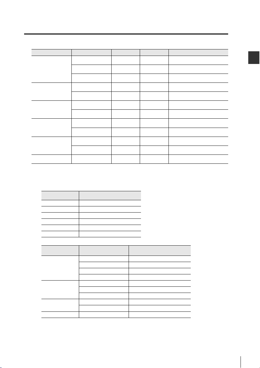
Available sensor amplifiers
Name Type of amplifier Main unit
GT2-71(M)(C)N
GT2-71(M)(C)P
GT2-75N
GT2-75P
GT2-100N
GT2-100P
GT-71A
GT-71AP
GT-75A
GT-75AP
High-accuracy Digital
Contact Sensor
General Purpose Digital
Contact Sensor
GT-70A Series
Multi-Purpose CCD
Laser Micrometer
Application Sensor
Thrubeam Laser
Detection Sensor
Static Sensor
SK-1000 Series
GT2 Series
*1
IG Series
CMOS Laser
*1
IL Series
IB Series
*1
*1
DIN-rail mount type
Panel mount type
Large display type
DIN-rail mount type
Panel mount type
DIN-rail mount type IG-1000 IG-1050
Panel mount type IG-1500 IG-1550
DIN-rail mount type IL-1000 IL-1050
Panel mount type IL-1000 IL-1050
DIN-rail mount type IB-1000 IB-1050
Panel mount type IB-1500 IB-1550
DIN-rail mount type SK-1000 SK-1050
*1 The GT-70A Series, GT-2 Series, IG Series, IL Series and IB Series can be connected solely.
In addition, two or more models can be used together.
The maximum connectable numbers for each model are as follows.
• When connecting 1 model only
Model
GT-70A Series 10 units
GT2 Series 15 units
IG Series 4 units
IL Series 8 units
IB Series 4 units
SK-1000 Series 8 units
Maximum connectable number
(DL not included)
• When connecting 2 models together
Model Amplifier used together
GT2 Series 10 units
GT-70A Series
GT2 Series
IG Series
IL Series IB Series 6 units
IG Series 6 units
IL Series 8 units
IB Series 6 units
IG Series 6 units
IL Series 6 units
IB Series 6 units
IL Series 6 units
IB Series 6 units
Expansion unit
GT2-72(C)N
GT2-72(C)P
GT2-76N
GT2-76P
-
GT-72A
GT-72AP
GT-76A
GT-76AP
Maximum connectable number
(DL not included)
Max. connectable number
(Main: 1, Expansion: 14, DL-RB1A: 1)
(Main: 1, Expansion: 14, DL-RB1A: 1)
(Main: 1, DL-RB1A: 1)
(Main: 1, Expansion: 9, DL-RB1A: 1)
(Main: 1, Expansion: 9, DL-RB1A: 1)
(Main: 1, Expansion: 3, DL-RB1A: 1)
(Main: 1, Expansion: 3, DL-RB1A: 1)
(Main: 1, Expansion: 7, DL-RB1A: 1)
(Main: 1, Expansion: 7, DL-RB1A: 1)
(Main: 1, Expansion: 3, DL-RB1A: 1)
(Main: 1, Expansion: 3, DL-RB1A: 1)
(Main: 1, Expansion: 7, DL-RB1A: 1)
15 units
15 units
1 unit
10 units
10 units
4 units
4 units
8 units
8 units
4 units
4 units
8 units
Mounting and Connecting the DL-RB1A
*2
11
Page 14

2
2-1 Connecting the Unit to Sensor Amplifiers
Note
• When connecting 3 or more models together
Model
Mounting and Connecting the DL-RB1A
GT-70A Series GT2 Series IL Series 8 units
When using 2 or more models together, the total connection number for each model must be the
maximum connectable number or less for connecting one model only.
(Example) When IB Series and IG Series are used together, sum of the 2 models must be 6
*2 As for the large display type, GT2-100 Series, up to 11 units of the sensor head can be connected
to 1 amplifier by adding the expansion board to the main unit.
GT2-100 Series cannot be used with other models.
DL-RB1A cannot be connected to the GT-70 Series.
Data that can be output
Type of amplifier
High-accuracy digital
contact sensor
GT2 Series
General purpose
digital
contact sensor
GT-70A Series
Multi-Purpose CCD
Laser Micrometer
IG Series
CMOS Laser
Application Sensor
IL Series
Thrubeam Laser
Detection Sensor
IB Series
Static Sensor
SK-1000 Series
*1 When using the calculation function in a display other than reference difference display on the
GT-70A Series and GT2 Series, the P.V. value (criterion value) for the main unit can be output by
selecting ID No. 15, while the R.V. value (raw value) can be output by selecting ID No. 00.
For more information about selecting ID numbers, refer to "I/O Connector" (page 15)
*2 If the measurement mode is set to the "Pin interval judgment mode" or "Pin diameter judgment
mode", the output data is fixed to "-099998". For details on the measurement mode, refer to the
IG Series User's Manual.
* For more information on data, refer to the User's Manual of each sensor amplifier.
Amplifier used
together 1
Other combinations 6 units
Amplifier used
together 2
Maximum connectable number
(DL not included)
units or less. In addition, the number of IB Series and IG Series must be 4 or less
respectively.
(Connectable) IB Series 4 units, IG Series 2 units, Total 6 units
(Not connectable) IB Series 5 units, IG Series 1 units, Total 6 units
Main unit
Expansion
unit
Main unit
Expansion
unit
Main unit
Expansion
unit
Main unit
Expansion
unit
Main unit
Expansion
unit
Main unit
Expansion
unit
Calculation
function OFF
P.V. values
(criterion values)
P.V. values
(criterion values)
P.V. values
(criterion values)
P.V. values
(criterion values)
P.V. values (criterion values)
P.V. values
(criterion values)
P.V. values
(criterion values)
P.V. values (criterion values)
P.V. values (criterion values)
P.V. values (criterion values)
Calculation function ON
Other displays
R.V. values (raw values)
R.V. values (raw values)
R.V. values (raw values)
R.V. values (raw values)
*2
---
---
Reference
difference display
*1
P.V. values
(criterion values)
P.V. values
(criterion values)
*1
R.V. values
(raw values)
P.V. values
(criterion values)
--
--
Calculation
dedicated mode
P.V. values
(criterion values)
P.V. values
(criterion values)
-
12
Page 15

2-1 Connecting the Unit to Sensor Amplifiers
2
Sensor amplifier
Expansion protective cover
End unit
End unit
Connecting the DL-RB1A to DIN rail mounted sensor amplifiers
1 Remove the expansion protective cover from the sensor amplifier that is to be connected to the
DL-RB1A.
2 Mount the DL-RB1A on a DIN rail and connect it to the sensor amplifier.
Make sure there is no space between the DL-RB1A and the sensor amplifier.
Mounting and Connecting the DL-RB1A
Caution
Sensor amplifier
Connector
Check that the sensor amplifier connector
(for DIN rail mounting) located on the side of
DL-RB1A is not installed at an angle as
shown in the illustration to the right.
Connecting the unit with its connector
installed crooked to a sensor amplifier may
damage the unit.
DL-RB1A
Sensor amplifier connector
DL-RB1A
3 Mount the end units (OP-26751, two units included) on either side of the sensor amplifier and
DL-RB1A unit and tighten the two screws on the top of each end unit.
(You can mount the end units in the same way you mount DL-RB1A.)
Make sure to firmly insert DL-RB1A all the way into the sensor amplifier.
Caution
Turning the power on when the unit is not inserted straight or firmly
connected could damage the unit.
13
Page 16
2
2-1 Connecting the Unit to Sensor Amplifiers
Remove the
protection sticker.
Expansion cable (cable length: 300 mm) (OP-35361)
Sensor amplifier connector
(for DIN rail mounting
of the DL-RB1A)
Expansion connector cover
Sensor amplifier connector
(for DIN rail mount type)
Expansion connector cover
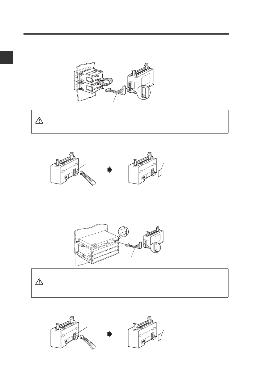
Connecting the DL-RB1A to panel mounted sensor amplifiers
1 Connect DL-RB1A to the sensor amplifiers using the optional expansion cable (OP-35361).
Mounting and Connecting the DL-RB1A
• Make sure the expansion cable is securely connected while the unit is
Caution
2
Remove the sensor amplifier connector with pliers (for DIN rail mounting) from the DL-RB1A unit when
using with panel mounted sensor amplifies and install the expansion connector cover supplied with the unit.
turned off. Turning the power on when the cable is not inserted straight or
firmly connected could damage the unit.
• Removing or inserting the cable while the power is on may damage the unit.
Connecting to a large display type sensor amplifier
1 Connect the sensor amplifier to the BCD Output Unit DL-RB1A using the optional expansion cable
(OP-35361).
Detach the
protection sticker
• Turn OFF the power before connecting the expansion cable and connect
Caution
• Inserting or pulling the cable when the power is turned ON may damage
2 Detach the sensor amplifier connector (for DIN rail mount type) of the BCD Output Unit
DL-RB1A with pliers and mount the attached expansion connector.
14
Detach the
protection sticker
Expansion cable (cable length: 300mm)
securely. Diagonal or otherwise improper insertion may damage the
equipment.
the equipment.
Page 17

2
2-1
Connector terminal area
I/O connector
1
3
5
7
9
11
13
15
17
19
21
23
25
27
29
31
33
2
4
6
8
10
12
14
16
18
20
22
24
26
28
30
32
34
Connecting the DL-RB1A to External Devices
I/O Connector
This section describes the pin assignments and each signal on the I/O connector.
Pin No.
Direction
1 Input IDSEL1
2 Input IDSEL2
3 Input IDSEL3
4 Input IDSEL4
5 Input DRQ Data request input
6 Output BCD DIGIT 1 (1) BCD 1st digit 1 x 10
7 Output BCD DIGIT 1 (2) BCD 1st digit 2 x 10
8 Output BCD DIGIT 1 (4) BCD 1st digit 4 x 10
9 Output BCD DIGIT 1 (8) BCD 1st digit 8 x 10
10 Output BCD DIGIT 2 (1) BCD 2nd digit 1 x 10
11 Output BCD DIGIT 2 (2) BCD 2nd digit 2 x 10
12 Output BCD DIGIT 2 (4) BCD 2nd digit 4 x 10
13 Output BCD DIGIT 2 (8) BCD 2nd digit 8 x 10
14 Output BCD DIGIT 3 (1) BCD 3rd digit 1 x 10
15 Output BCD DIGIT 3 (2) BCD 3rd digit 2 x 10
16 Output BCD DIGIT 3 (4) BCD 3rd digit 4 x 10
17 Output BCD DIGIT 3 (8) BCD 3rd digit 8 x 10
18 Output BCD DIGIT 4 (1) BCD 4th digit 1 x 10
19 Output BCD DIGIT 4 (2) BCD 4th digit 2 x 10
20 Output BCD DIGIT 4 (4) BCD 4th digit 4 x 10
21 Output BCD DIGIT 4 (8) BCD 4th digit 8 x 10
22 Output BCD DIGIT 5 (1) BCD 5th digit 1 x 10
23 Output BCD DIGIT 5 (2) BCD 5th digit 2 x 10
24 Output BCD DIGIT 5 (4) BCD 5th digit 4 x 10
25 Output BCD DIGIT 5 (8) BCD 5th digit 8 x 10
26 Output BCD DIGIT 6 (1) BCD 6th digit 1 x 10
27 Output BCD DIGIT 6 (2) BCD 6th digit 2 x 10
28 Output BCD DIGIT 6 (4) BCD 6th digit 4 x 10
29 Output BCD DIGIT 6 (8) BCD 6th digit 8 x 10
30 Output BCD SIGN
31 Output BCD STB
32 Output ALARM
33
Common
34
Common
*1Be sure to load the BCD output (Pin Nos. 6 to 30) when the
strobe output (Pin No. 31) is turned on.
*2Alarm output will be turned off when the alarm is generated.
(It is turned on in normal conditions.)
Signal name Description
*1
*2
COM Common
COM Common
ID No. selection input 1
ID No. selection input 2
ID No. selection input 3
ID No. selection input 4
BCD data polarity
code
Strobe output
Alarm output
Mounting and Connecting the DL-RB1A
0
0
0
0
1
1
1
1
2
2
2
2
3
3
3
3
4
4
4
4
5
5
5
5
15
Page 18

2
2-1 Connecting the DL-RB1A to External Devices
Pin Nos. 1 to 4: ID No. selection input
Select the ID number for the sensor amplifier that outputs data by changing the combination of input
signals that are turned on or off. For information about ID numbers, refer to "Sensor Amplifier ID
Mounting and Connecting the DL-RB1A
Number Assignments" (page 24).
Pin No. 4
*1
ID No.
000000
010001
020010
030011
040100
050101
060110
070111
081000
091001
101010
111011
121100
131101
141110
151111
IDSEL4
*1 The IG Series and IB Series do not use ID No. 04 to 15.
The GT-70A Series does not use ID No. 10 to 14.
The IL Series and SK-1000 Series does not use ID No. 08 to 15.
ID No. 15 outputs the P.V. value for the main unit when using a calculation function other than
reference difference display on the GT2 Series or GT-70A Series. (During this time, ID No. 00
outputs the R.V. value for the main unit.)
For information about the calculation function, refer to the User's Manual of each sensor amplifier.
Pin No. 5: Data request input (DRQ)
Within 2 ms after the DRQ input is turned on, the data from the sensor amplifier with the selected ID
number is updated and output through BCD output. For more information, refer to "Chapter 3:
Advanced Functions" (Page 23).
Pin No. 3
IDSEL3
Pin No. 2
IDSEL2
Pin No. 1
IDSEL1
Pin Nos. 6 to 30: BCD output and BCD data polarity code
Represents a signed six digit figure depending on the combination of outputs that are turned on or
off.
Set the DL-RB1A output logic with the advanced setting switch No. 1. For more information on
advanced setting switches, refer to "Part Names and Functions" (page 6).
Output logic Transistor output Bit
Negative logic
(Factory default)
Positive logic
The following table shows examples of BCD output (pin Nos. 6 to 30).
Reference
Detection
data from
the sensor
amplifiers
+000000
+123456
-123456
+ABCDEF
* When the output logic is negative logic, the output is turned off for 0 and turned on for 1.
When the output logic is positive logic, the output is turned on for 0 and turned off for 1.
16
30 29 28 27 26 25 24 23 22 21 20 19 18 17 16 15 14 13 12 11 10 9 8 7 6
BCD 6th digit BCD 5th digit BCD 4th digit BCD 3th digit BCD 2nd digit BCD 1st digit
Signed
8 4 2 1 8 4 2 1 8 4 2 1 8 4 2 1 8 4 2 1 8 4 2 1
0 000000000000000000000000
0 000100100011010001010110
1 000100100011010001010110
0 101010111100110111101111
OFF 0
ON 1
ON 0
OFF 1
Pin No.
Page 19
2-1 Connecting the DL-RB1A to External Devices
2
Note
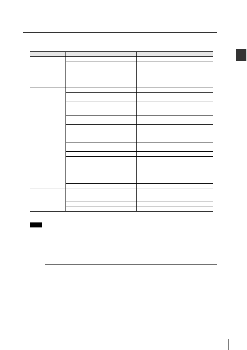
The following special output occurs depending on the sensor amplifier data. For information on
conditions that produce an alarm, refer to "Pin No. 32: Alarm output".
Sensor amplifier Data state Alarm output
-999998 No data ON
High-precision Digital
Contact Sensor
GT2 Series
General Purpose
Digital
Contact Sensor
GT-70A Series
Multi-Purpose CCD
Laser Micrometer
IG Series
CMOS Laser
Application Sensor
IL Series*
Thrubeam Laser
Detection Sensor
IB Series
Static Sensor
SK-1000 Series
* If the source of the alarm output is on the DL-RB1A, the sensor amplifier continues to show a normal display.
When using the GT2-100 Series, “-999998” is output if the data of the ID outside the range of the valid ID setting is read.
+EEEEEE Alarm OFF
+999999 Exceed upper limit ON
-999999 Exceed lower limit ON
-999998 No data ON
+EEEEEE Alarm OFF
+999999 Exceed upper limit ON FFFF
-999999 Exceed lower limit ON -FFFF
-099998 No data ON
+EEEEEE Error OFF
+099999 Exceed upper limit ON 99.999 or FFFF
-099999 Exceed lower limit ON
-099998 No data ON
+EEEEEE Error OFF
+099999 Exceed upper limit ON 99.999 or FFFF
-099999 Exceed lower limit ON
-099998 No data ON
+EEEEEE Error OFF
+999999 Exceed upper limit ON -99.998 or less, or FFFF
-999999 Exceed lower limit ON -999.98 or -FFFF
-099998 No data ON
+EEEEEE Error OFF
+099999 Exceed upper limit ON 99.999 or FFFF
-099999 Exceed lower limit ON -99.998 or less, or -FFFF
Sensor amplifier display
-------
Error display
or abnormal
+100.0000 or less,
-100.0000 or less,
Error display
or abnormal
Error display
or abnormal
-99.998 or less,
Error display
or abnormal
-99.998 or less,
Error display or
Error display
or abnormal*
*
or FFFF
or -FFFF
-------
*
-------
*
or -FFFF
-------
*
or -FFFF
-------
abnormal*
-------
Mounting and Connecting the DL-RB1A
• DL-RB1A does not output decimal points. If there is a decimal point in the sensor amplifier
data, it will be dropped.
[Ex.] When the GT2 Series is connected, the detection data "+12.3456"
is output to the DL-RB1A as "+123456".
• The number of digits sent out of the BCD output cannot be changed. (This does not affect
the number of digits displayed on the sensor amplifier.)
• The GT2 Series sensor amplifier can display up to 7 digits, but DL-RB1A can only output
up to 6 digits.
Pin No. 31: Strobe output
Strobe output is turned on when data can be read from the external device.
When the strobe output is turned off, the BCD output cannot be verified.
Pin No. 32: Alarm output
Alarm output is turned on normally. It is turned off when an alarm occurs.
When an alarm occurs, "+EEEEEE" is output as the BCD data and polarity code.
• The time after the power is turned on but before the first BCD output is confirmed
• When updating the BCD output, if the selected ID number for the sensor amplifier does not exist
• When updating the BCD output, if there is an error with the selected ID number for the sensor
amplifier
• When there is overcurrent error on one of the outputs (Pin Nos. 6 to 32)
• Until the initialization is completed if the main unit (ID: 00) is initialized when it is connected to the
GT2-100N/100P.
* For more information on errors, refer to the User's Manual of each sensor amplifier.
17
Page 20

2
2-1 Connecting the DL-RB1A to External Devices
Main circuit
(Short-circuit current 1 mA max.)
+5V
1 to 5
33 or 34*
Internal circuit
6 to 32 (20 mA max.)
33 or 34*
IN
COM
Photocoupler insulation
PLC etc.
Internal circuit
Overcurrent protect circuit
Input circuit diagram
Input circuit (Pin Nos. 1 to 5)
Mounting and Connecting the DL-RB1A
* The terminals for pin Nos. 33 and 34 are used in common with 0 V (the blue wire of the sensor
amplifier main unit).
Output circuit (Pin Nos. 6 to 32)
* The terminals for pin Nos. 33 and 34 are used in common with 0 V (the blue wire of the sensor
amplifier main unit).
18
Page 21
2
Combining and Wiring Connectors
Remove
the screws
Housing
Vertical hood cover
OP-23139 (34-pin)
Tilted hood cover
OP-42224 (34-pin)
Hood cover
2-1 Connecting the DL-RB1A to External Devices
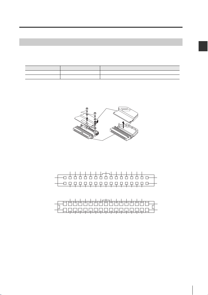
To connect the DL-RB1A to external devices, the cable from each device must be wired to the
connector (MIL connector, female 34-pin).
Therearetwotypesofconnectors.
Model Shape Structure
OP-23139 34-pin, vertical hood cover 1 hood cover, 1 housing, 40 contacts
OP-42224 34-pin, tilted hood cover 1 hood cover, 1 housing, 40 contacts
Connectors
An upper and lower cover is installed on the connector. When performing the wiring, remove both
covers.
I/O connector pin assignments
Front
Back
Mark
1
2
33
34
579
3
4
6
11 13 15 17 19 21 23 25 27 29 31
1210814 201816 22 282624 30 32
1113151719212325272931
68
101214161820222426283032
3579
4
33
34
Mark
1
2
Mounting and Connecting the DL-RB1A
19
Page 22
2
2-1 Connecting the DL-RB1A to External Devices
Precautions when wiring (OP-23139 and OP-42224)
Carefully follow the precautions below when performing wiring.
• Use a single shielded cable.
Mounting and Connecting the DL-RB1A
• Use the following type of compliant cable:
Cable size: AWG24 to 22 (stranded)
Cross-section: 0.2 to 0.3 mm
Cable sheath diameter: 1.5 to 1.1
• Cut the end of the cable straight across.
• After performing the wiring, check that the cable is securely held in the clamp and that it is inserted
firmly.
• Cut the cable clearly so that no loose threads remain. (The sheath does not need to be removed.)
• Use the thin cable contacts OP-30594 (200 pieces included) for AWG28 to 26.
(Use this together with OP-23139 or OP-42224.)
Cable size: AWG28 to 26
Cross-section: 0.08 to 0.14 mm
Cable sheath diameter: 1.3 to 1.1
2
2
20
Page 23
2-1 Connecting the DL-RB1A to External Devices
2
Note
Contact breaking point
Carrier end
Crimper
Crimping groove
Cover
Guide
Contact
Figure A
Cable
Figure B
Cable
Crimper
Cover
Guide
Side view
Handle
Pin for removing the contact
Cover
Contact housing area
Guide
Crimper
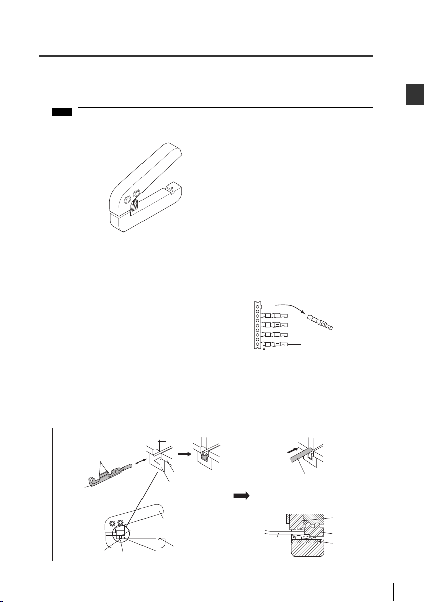
Dedicated crimping tool
You can use the dedicated crimping tool to easily crimp the ends of the cable.
Use the following dedicated crimping tool for wiring.
If you do not use the dedicated crimping tool, you must solder the connection.
Dedicated crimping tool: Model OP-21734
Wiring to the connector
This section explains how to use the dedicated crimping tool to perform wiring. Make sure to have
contacts, housing, and the cable beforehand.
1 To remove the contact, bend at the breaking point.
For additional contacts use OP-22189
(includes 200 contacts).
Mounting and Connecting the DL-RB1A
2 Fully insert the contact straight into the contact
3 Fully insert the cable straight into the dedicated crimping tool so that it lays in the crimping grove of the
housing area of the dedicated crimping tool as in
(Figure A) .
contact. (Figure B)
(The cable sheath does not need to be removed.)
21
Page 24
2
2-1 Connecting the DL-RB1A to External Devices
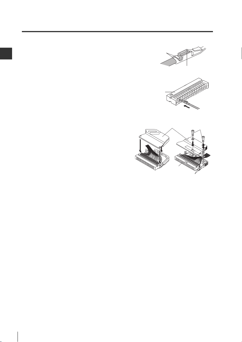
4 Press down on the handle of the dedicated crimping tool until the
clamp wraps completely around the cable.
Gently tug on the cable to remove the cable with crimped
Mounting and Connecting the DL-RB1A
contact from the housing area of the dedicated crimping tool.
5 Fully insert the cable straight into a groove in the house that
does not already contain a contact.
• Gently tug on the cable to check that the contact is securely
inserted.
• Completely insert the contact in the housing.
6 With the contacts inserted into the housing, install the
hood covers.
7 Use a cable tie as shown in the figure to secure the cable in place.
Clamp wraps
around the cable
Housing
Hood cover
Housing
Fully insert the cable
Attach the screws
Align this area
22
Page 25

3
3
Advanced Functions
Advanced Functions
This chapter describes the I/O timing for each operation mode and the data
processing time.
3-1 Data Processing and Operation Modes . . . . . . . . . . . 24
23
Page 26
3
3-1 Data Processing and Operation Modes
Note
ID No. 00
Main
unit
Expansion
unit
Expansion
unit
Expansion
unit
Expansion
unit
01 02 13 14
Sensor amplifiers DL-RB1A
ID No. Sensor amplifier
00
01
02
13
14
Main
unit
Expansion
units
Expansion
units
Expansion
units
Expansion
units
DL-RB1A
Sensor amplifiers
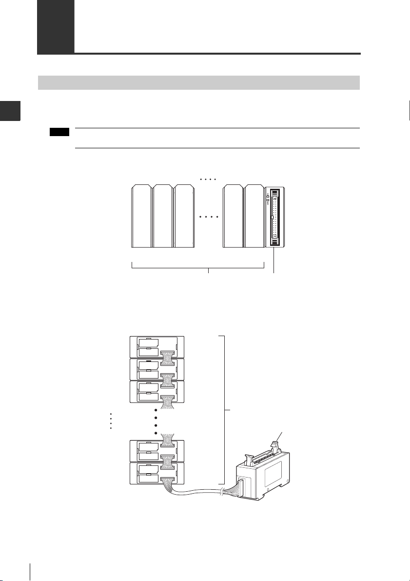
Sensor Amplifier ID Number Assignments
When the sensor amplifier that is connected to DL-RB1A supports expansion units, the sensor
amplifier ID number "00" is automatically assigned to the main unit and ID numbers "01 to 14" to the
Advanced Functions
expansion units.
The ID number for the sensor amplifier cannot be changed.
DIN rail mounted sensor amplifiers
Panel mounted sensor amplifiers
24
Page 27

3
Large display type sensor amplifiers (GT2-100N/100P)
ID:00 ID:01
ID:02 ID:03 ID:04
ID:05 ID:06 ID:07
ID:08 ID:09
ID:10
DL-RB1A
GT2-100N/100P
ID:00 ID:10
:ID number 00 to 10
Head expansion
board
Sensor amplifiers
3-1 Data Processing and Operation Modes
Advanced Functions
25
Page 28
3
3-1 Data Processing and Operation Modes
Sensor amplifier
DL-RB1A
Detected data update
DL-RB1A data processing complete
Detection
T1
T2
1. Data processing time for the number of sensor
amplifiers connected without using the calculation
function (ID No.15)
When using the GT2-100N/100P, add 50 ms to the above value.
Number of connected
sensor amplifiers
Data processing time (T2)
GT-70A Series/
GT2 Series
IG Series/
IB Series
IL Series
/
SK-1000 Series
1 7 ms 5 ms 9 ms
2 9 ms 10 ms 11 ms
3 13 ms 12 ms 14 ms
4 15 ms 16 ms 18 ms
5 19 ms - 20 ms
6 21 ms - 24 ms
7 25 ms - 27 ms
8 27 ms - 31 ms
931 ms-10 33 ms - 11 37 ms - 12 39 ms - 13 43 ms - 14 45 ms - 15 49 ms - -
2.
Data processing time for the number of
sensor amplifiers connected while using
the calculation function (ID No.15)
When using the GT2-100N/100P, add 75 ms to the
above value.
Number of connected
sensor amplifiers
T2
1 10.5 ms
2 13.5 ms
3 19.5 ms
4 22.5 ms
5 28.5 ms
6 31.5 ms
7 37.5 ms
8 40.5 ms
9 46.5 ms
10 49.5 ms
11 55.5 ms
12 58.5 ms
13 64.5 ms
14 67.5 ms
15 73.5 ms
Communication Unit Data Update Time
After the sensor is detected, the DL-RB1A can output data after the sensor amplifier response time
*
and DL-RB1A data processing time (T2) have passed.
(T1)
Advanced Functions
DRQ input from an external device starts after T1 and T2 have passed.
* For more information on sensor amplifier response time, refer to the manual supplied with the
sensor amplifiers.
Time chart
T1: Sensor amplifier response time
T2: DL-RB1A data processing time
DL-RB1A data processing time (T2)
The processing time for T2 varies depending on the sensor amplifier calculation function and the
number of sensor amplifiers that are connected.
26
* ID No. 15 outputs the P.V. value for the main unit when using a calculation function other than the
reference difference display on the GT-70A Series.
During this time, ID No. 00 outputs the P.V. value for the main unit.
ID No. 15 is not used when the calculation function is not used or when reference difference display is used.
When using reference difference display, the processing time for ID Nos. 01 to14 becomes the
same as the processing time for ID No. 15.
For information on the calculation function, refer to the manual supplied with the sensor amplifiers.
Page 29

3-1 Data Processing and Operation Modes
3
Note
Operation Modes
There are three types of operations modes for DL-RB1A: OUT mode, OR mode, and TIMER mode.
Different ON/OFF combinations of the advanced setting switches can be used to toggle between the
operation modes. For more details, see to Advanced setting switches on (page 7) .
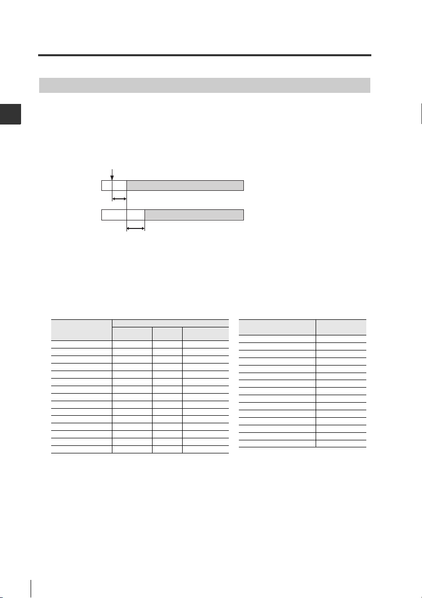
OUT mode
This is an all-purpose mode that uses BCD output to output data from the sensor amplifier with the
selected ID No. when the DRQ input from the external device is switched.
Set the external device so that there is at least 2 ms before turning DRQ input on and after
turning DRQ input off.
Time chart
ID No.
selection input
DRQ input
(1) ID No. 01 selected ID No. 02 selected
2 ms min. 2 ms min.
2 ms min. 2 ms min. 2 ms min.
(2) ONOFF (5) OFF ON OFF
2 ms max. 2 ms max.
Advanced Functions
Strobe output
BCD output
(Previous data) (4) ID No. 01 BCD data ID No. 02 BCD data
(3) ONOFF OFF ON OFF
2 ms max. 2 ms max.
Data update Data update
(1) An external device inputs "ID No. 01" as the ID No. selection.
(2) After at least 2 ms have passed, an external device turns on the DRQ input.
(3) Within 2 ms of the DRQ input turning on, DL-RB1A updates the BCD output and turns on the
strobe output.
(4) The external device confirms that the strobe output is on and imports the BCD output.
(5) An external device turns off the DRQ input. (The strobe output turns off within 2 ms and the BCD
output is held until the DRQ input turns on again.)
27
Page 30

3
3-1 Data Processing and Operation Modes
Note
Internal circuit
6 to 32
33 or 34
IN
COM
Photocoupler insulation
DL-RB1A Input to PLC etc.
Overcurrent protect circuit
Internal circuit
6 to 32
33 or 34
DL-RB1A
Overcurrent protect circuit
A
B
Internal circuit
OR mode
This mode is used when reading BCD output from multiple DL-RB1A units with one external device.
Set the external device so that there at least 2 ms before turning DRQ input on and after
Advanced Functions
Sample wiring
turning DRQ input off.
When sending BCD output from two DL-RB1A units to one external device.
- Perform OR wiring from the two BCD outputs to the external device input.
- Perform OR wiring from the two strobe outputs to the external device input or wire each input
independently.
- Wire both of the DRQ inputs independently from the two outputs on the external device (OR
wiring cannot be performed with the DRQ).
28
Page 31

3
Time chart
ID No.
selection input
(1) ID No. 01 selected (6) ID No. 02 selected
DL-RB1A
DRQ input
(2) ONOFF (5) OFF
DL-RB1A
strobe output
(3) ONOFF OFF
DL-RB1A
DRQ input
(7) ONOFF (10) OFF
DL-RB1A
strobe output
(8) ONOFF OFF
DL-RB1A
BCD output
Data update
OFF* OFF*
DL-RB1A
BCD output
Data update
OFF*OFF*
2 ms min. 2 ms min.
2 ms min.
2 ms min.
2 ms max.
2 ms max.
2 ms max.
2ms max.
(4) ID No. 01 BCD data
(9) ID No. 02 BCD data
*BCD output (pin Nos. 6 to 31) and alarm output (pin No. 32) are all turned off, regardless of whether the
output logic is positive or negative.
A
A
A
B
B
B
A
A
A
A
A
B
B
B
B
B
3-1 Data Processing and Operation Modes
Advanced Functions
(1) An external device inputs "ID No. 01" as the ID No. selection.
(2) After at least 2 ms have passed, DL-RB1A DRQ input from the external device turns on.
(3) Within 2 ms of the DRQ input turning on, DL-RB1A turns on the strobe output.
(4) The external device confirms that the strobe output is on and imports the DL-RB1A BCD
output.
(5) An external device the DL-RB1A DRQ input. (The strobe output and DL-RB1A BCD output
turn off within 2 ms.)
(6) An external device inputs "ID No. 02" as the ID No. selection.
(7) After at least 2 ms have passed, DL-RB1A DRQ input from the external device turns on.
(8) Within 2 ms of the DRQ input turning on, DL-RB1A turns on the strobe output.
(9) The external device confirms that the strobe output is on and imports the DL-RB1A BCD
output.
(10)An external device turns off the DL-RB1A DRQ input. (The strobe output and DL-RB1A
BCD output turn off within 2 ms.)
29
Page 32
3
3-1 Data Processing and Operation Modes
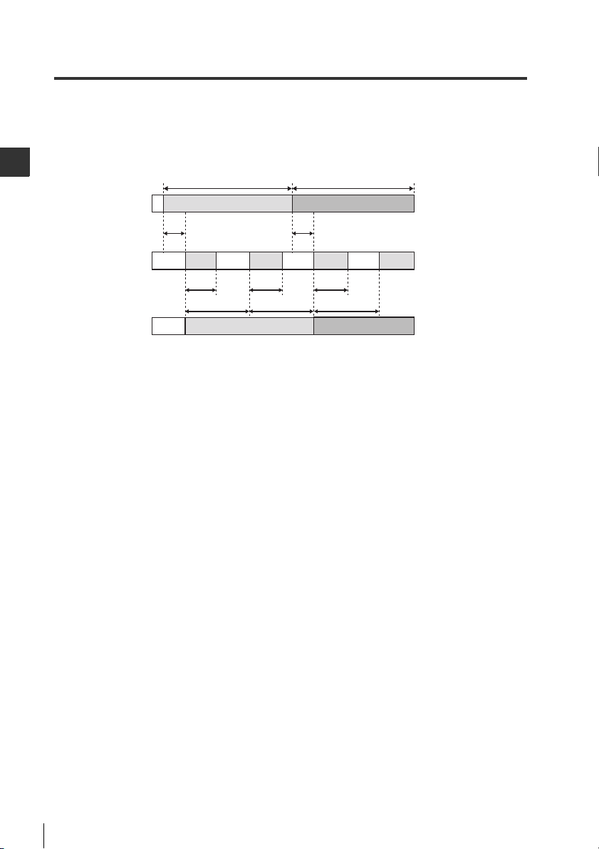
ID No. selection
input
(1) ID No. 01 selection
(4) ID No. 02 selection
BCD output
2 ms.
max.
(2), (3) ID No. 01 BCD data (5) ID No. 02 BCD data
Strobe output
OFF OFF OFF OFF
ONON ON ON
T/2
T T T
T/2 T/2
2 ms.
max.
2 ms min. 2 ms min.
T :BCD output update cycle (Set T with the advanced setting switches Nos. 4 to 6. For information on
advanced setting switches, refer to
"(1) Advanced setting switches" (Page 7)
.)
TIMER mode
Even without the DRQ input from an external device, the sensor amplifier can periodically output
BCD data.
The DRQ input is ignored.
Time chart
Advanced Functions
(1) An external device inputs "ID No. 01" as the ID No. selection.
(2) The external device imports BCD output from ID No. 01 with an update cycle that starts no more
than 2 ms later.
(3) At the next BCD update cycle, if the ID No. has not changed, the BCD output for the same ID No.
is updated.
(4) An external device inputs "ID No. 02" as the ID No. selection.
(5) The external device imports BCD output from ID No. 02 with an update cycle that starts no more
than 2 ms later.
30
Page 33

4
4
Appendix
Appendix
This appendix describes the specifications and dimensions of DL-RB1A.
4-1 Specifications . . . . . . . . . . . . . . . . . . . . . . . . . . . . . . .32
31
Page 34

4
4-1 Specifications
Performance specifications
The following table shows the performance specifications for DL-RB1A.
Model DL-RB1A
Appendix
Power supply voltage
Current consumption 27 mA max.
Number of connected sensor
amplifiers
Indicators Alarm indicator (red), power indicator (green)
I/O terminal 34-pin connector (MIL standard)
Control outputs
Control inputs
Environmenta
l
resistance
Material Main unit housing: polycarbonate
Weight Approx. 46g
Accessories Instruction manual, 2 end units, expansion connector cover, switch protection seal
* The number of connectable sensor amplifiers varies depending on the model to be connected.
Item Specifications
Surrounding air
temperature
Relative
humidity
Vibration 10 to 55 Hz, compound amplitude 1.5 mm, 2 hours for each of XYZ axes
For details, refer to "Available sensor amplifiers" (page 11).
20 to 30 VDC, including 10% ripple (P-P). Class2
(supplied from the connected sensor amplifier)
Varies depending on the model
BCD output: 4 (1 digit) x 6 digits, code output, strobe output, alarm output
NPN open collector: 40 V, 20 mA max., residual voltage 1 V max.
Positive/negative logic: Switchable
ID selection input: 4 inputs, data request input
Non-voltage input (with contacts, without contacts), input time 2 ms min., short-circuit
current 1 mA
-10 C to +55 C (No freezing)
35 to 85% RH (No condensation)
*
32
Page 35

4
Dimensions
22.5
37.1
53.4
(57.8)
21.1 35.4
70
When the unit is mounted on a DIN rail
When the optional mounting bracket (OP-60412) is used
53.4
60.9
37.1
<Header-1>4-1 Specifications
Appendix
31.4 15
70
22.5
5
2-ø3.4
2-(4.4x3.4)
15
28.5
35.5
33
Page 36

4
<Header-1>4-1 Specifications
Appendix
MEMO
34
Page 37

Index
The following index provides a list of terms used in this manual in alphabetical order.
A
Advanced setting switches ..................................7
Available sensor amplifiers ................................11
C
Checking the package contents ..........................6
Combining and Wiring Connectors ....................19
Connectors ...................................................19
Dedicated crimping tool ...............................21
Precautions when wiring ...............................20
Wiring to the connector .................................21
Communication Unit Data Update Time ............26
Time chart .....................................................26
Connecting the DL-RB1A to external devices ...15
Connecting the unit to sensor amplifiers ...........10
Available sensor amplifiers ...........................11
Connecting the DL-RB1A to DIN rail
mounted sensor amplifiers ..........................13
Connecting the DL-RB1A to panel
mounted sensor amplifiers ..........................14
Data that can be output ................................12
D
Data Processing and Operation Modes ............24
Data that can be output .....................................12
Dimensions ........................................................33
When the optional mounting bracket
(OP-60412) is used ......................................33
When the unit is mounted on a DIN rail ........33
P
Part names and functions ................................... 6
Performance specifications .............................. 32
S
Sensor Amplifier ID Number Assignments ........ 24
DIN rail mounted sensor amplifiers .............. 24
Panel mounted sensorr amplifiers ................ 24
Specifications .................................................... 32
T
TIMER mode ...................................................... 30
Index
I
I/O Connector .....................................................15
Input circuit diagram ..........................................18
M
Mounting the unit ...............................................10
Mounting the unit on a DIN rail ..........................10
O
Operation Modes ...............................................27
OR mode ............................................................28
OUT mode ..........................................................27
35
Page 38

Revision History
Date of printing Version Revision contents
June 2008
September 2008
July 2009
November 2009
February 2010
June 2010
August 2010
September 2014
The GV-T Series is added.
The name of the GV-T Series is changed to the name of IG Series.
The IL Series is added.
The IB Series is added.
The SK-1000 Series is added.
Official release
Second edtion
Revised first edition
Second revision, first edition
Third revision, first edition
Second edition
Third edition
Fourth edition
Page 39

WARRANTIES AND DISCLAIMERS
(1) KEYENCE warrants the Products to be free of defects in materials and workmanship for a
period of one (1) year from the date of shipment. If any models or samples were shown to Buyer,
such models or samples were used merely to illustrate the general type and quality of the Products
and not to represent that the Products would necessarily conform to said models or samples. Any
Products found to be defective must be shipped to KEYENCE with all shipping costs paid by Buyer
or offered to KEYENCE for inspection and examination. Upon examination by KEYENCE,
KEYENCE, at its sole option, will refund the purchase price of, or repair or replace at no charge any
Products found to be defective. This warranty does not apply to any defects resulting from any
action of Buyer, including but not limited to improper installation, improper interfacing, improper
repair, unauthorized modification, misapplication and mishandling, such as exposure to excessive
current, heat, coldness, moisture, vibration or outdoors air. Components which wear are not
warranted.
(2) KEYENCE is pleased to offer suggestions on the use of its various Products. They are only
suggestions, and it is Buyer's responsibility to ascertain the fitness of the Products for Buyer's
intended use. KEYENCE will not be responsible for any damages that may result from the use of
the Products.
(3) The Products and any samples ("Products/Samples") supplied to Buyer are not to be used
internally in humans, for human transportation, as safety devices or fail-safe systems, unless their
written specifications state otherwise. Should any Products/Samples be used in such a manner or
misused in any way, KEYENCE assumes no responsibility, and additionally Buyer will indemnify
KEYENCE and hold KEYENCE harmless from any liability or damage whatsoever arising out of any
misuse of the Products/Samples.
(4) OTHER THAN AS STATED HEREIN, THE PRODUCTS/SAMPLES ARE PROVIDED WITH NO
OTHER WARRANTIES WHATSOEVER. ALL EXPRESS, IMPLIED, AND STATUTORY WARRANTIES,
INCLUDING, WITHOUT LIMITATION, THE WARRANTIES OF MERCHANTABILITY, FITNESS FOR A
PARTICULAR PURPOSE, AND NON-INFRINGEMENT OF PROPRIETARY RIGHTS, ARE
EXPRESSLY DISCLAIMED. IN NO EVENT SHALL KEYENCE AND ITS AFFILIATED ENTITIES BE
LIABLE TO ANY PERSON OR ENTITY FOR ANY DIRECT, INDIRECT, INCIDENTAL, PUNITIVE,
SPECIAL OR CONSEQUENTIAL DAMAGES (INCLUDING, WITHOUT LIMITATION, ANY DAMAGES
RESULTING FROM LOSS OF USE, BUSINESS INTERRUPTION, LOSS OF INFORMATION, LOSS
OR INACCURACY OF DATA, LOSS OF PROFITS, LOSS OF SAVINGS, THE COST OF
PROCUREMENT OF SUBSTITUTED GOODS, SERVICES OR TECHNOLOGIES, OR FOR ANY
MATTER ARISING OUT OF OR IN CONNECTION WITH THE USE OR INABILITY TO USE THE
PRODUCTS, EVEN IF KEYENCE OR ONE OF ITS AFFILIATED ENTITIES WAS ADVISED OF A
POSSIBLE THIRD PARTY'S CLAIM FOR DAMAGES OR ANY OTHER CLAIM AGAINST BUYER. In
some jurisdictions, some of the foregoing warranty disclaimers or damage limitations may not
apply.
BUYER'S TRANSFER OBLIGATIONS: If the Products/Samples purchased by Buyer are to be
resold or delivered to a third party, Buyer must provide such third party with a copy of this
document, all specifications, manuals, catalogs, leaflets and written information provided to Buyer
pertaining to the Products/Samples.
Page 40

Copyright (c) 2014 KEYENCE CORPORATION. All rights reserved. 189035E 1094-1 410GB Printed in Japan
 Loading...