

Page 1
427GB
PROFINET Communication Unit
DL-PN1 (IB)
User's Manual
Read this manual before use.
Keep this manual in a safe place for future reference.
Page 2
Introduction
Important
Point
Reference
WARNING
CAUTION
NOTICE
This manual describes the basic operations and hardware functions of the DL-PN1.
Read the manual carefully to ensure safe performance and function of the DL-PN1.
Keep this manual in a safe place for future reference.
Ensure that the end user of this product receives this manual.
Symbols
The following symbols alert you to matters concerning the prevention of injury and
product damage.
It indicates a hazardous situation which, if not avoided, could result in
death or serious injury.
It indicates a hazardous situation which, if not avoided, could result in
minor or moderate injury.
It indicates a situation which, if not avoided, could result in product
damage as well as property damage.
It indicates cautions and limitations that must be followed during
operation.
It indicates additional information on proper operation.
It indicates tips for better understanding or useful information.
Page 3

Overview of PROFINET
What is PROFINET?
PROFINET is an open industrial networking standard developed and maintained by the
PI (PROFINET International).
All supported devices can use the communication network regardless of the vendor.
PROFINET allows easy integration with the currently used field bus (such as
PROFIBUS), enabling you to protect the existing assets without modifying the legacy
system.
The PROFINET communication for the DL-PN1 series supports the PROFINET I/O
communication, which transmits data between I/O controllers (PLC etc.) and I/O
devices, and complies with Conformance Class A.
The PROFINET I/O communication offers the following two types of communication
methods for cyclic data: Real-time communication (RT) and isochronous real-time
communication (IRT).
Real-time communication provides similar communication performance as the existing
field bus, such as the device control in normal factory automation, using Ethernet. The
isochronous real-time communication is capable of meeting stringent real-time
requirements, including synchronized motion control.
The real-time communications offer the following two types of communications: Data I/O
communication for sending and receiving data periodically, and record data
communication for sending and receiving commands/responses at arbitrary timings. In
the data I/O communication, you can set the Update time (Communication cycle) based
on the priority of the data to be sent/received, enabling sending/receiving of data with
adjusted overall communication load. The record data communication is used for
communication applications that require little punctuality (unlike the data I/O
communication).
The DL-PN1 Series supports real-time data I/O communication and record data
communication.
427GB
1
Page 4
Reference
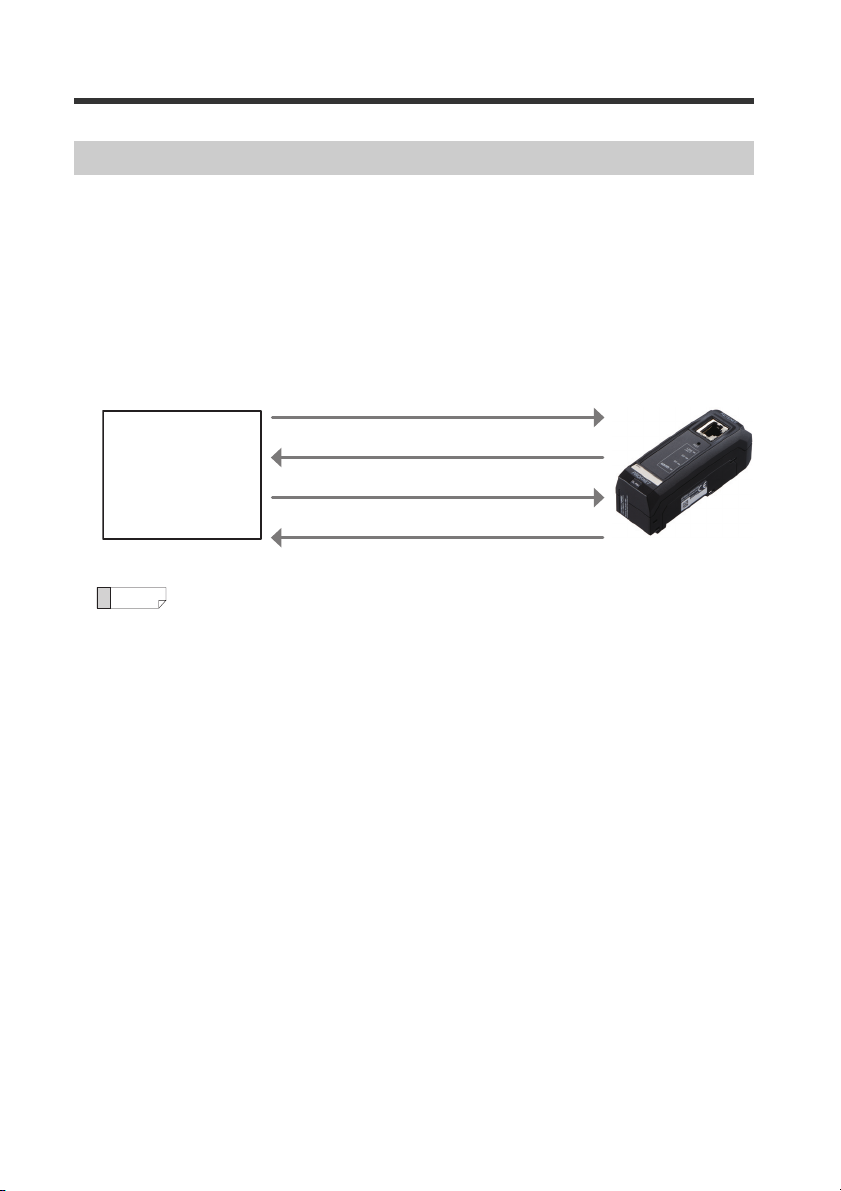
Specifying the IP address using the DCP protocol
In the PROFINET communication, you can specify the IP address of I/O devices using
the DCP protocol (Discovery and Configuration Protocol).
The DCP protocol offers two methods for setting the IP address.
(1) The IP address can be set by the I/O controller based on the device name
information of the I/O device.
(2) The IP address and device name of the I/O device can be set by the I/O supervisor
(PC, etc.).
(1)
Check the presence of an I/O device
PROFINET
communication
I/O Controller
(2) Response
(3) Set the IP address
(4) Response
If the IP address of the I/O device will be set by the I/O controller, the I/O
device name must match the name in the config of the I/O controller.
I/O device
2
- PROFINET Communication Unit DL-PN1 User's Manual (IB) -
Page 5

Communicating with the IB Series
Point
For DIN rail mounting type
ID number 01
Main
unit
Expansion
unit
Expansion
unit
Expansion
unit
02 03 04 00
Slot number 01 02 03 04 00
DL-PN1
LINK
/ACT
RST
SF
BF
For panel mounting type
Types and Number of Connectable Sensor Amplifiers
Name Amplifier form Main unit Expansion unit Maximum number of connectable units
DIN rail mounting type IB-1000 IB-1050
IB Series
Panel mounting type IB-1500 IB-1550
4
(1 main unit, 3 expansion units)
4
(1 main unit, 3 expansion units)
The DL-PN1 can connect to multiple sensor amplifiers (a single main unit and multiple
expansion units) which support D-bus. "D-bus" is the name of KEYENCE's wiring-saving
system for sensor amplifiers.
Different types of sensor amplifiers with D-bus support can be connected to a single
DL-PN1 unit.
How many and what types of sensor amplifiers can be connected depends on the
sensor amplifiers or units to be connected. Please inquire for details.
Assigning ID Numbers and Slot Numbers
Several sensor amplifiers can be connected to the DL-PN1. ID numbers and slot
numbers for data identification are assigned to each sensor amplifier.
The method for assigning ID numbers and slot numbers is as follows:
• The numbers are assigned in order, starting from the sensor amplifier that is the main
unit. (Optional numbers cannot be assigned.)
• 00 is assigned as the ID number and slot number of the DL-PN1.
• You cannot change the ID numbers and slot numbers assigned to
the sensor amplifiers.
• In this manual, ID number 00 to ID number 04 are denoted as ID00 to
ID04, and slot number 00 to slot number 04 are denoted as Slot0 to
Slot04 respectively.
- PROFINET Communication Unit DL-PN1 User's Manual (IB) -
ID number
Slot number
01
02
...
03
04
Sensor amplifier
01
02
...
03
04
Main unit
Expansion unit
...
Sensor amplifier
Expansion unit
Expansion unit
Slot number 00
ID number 00
3
Page 6
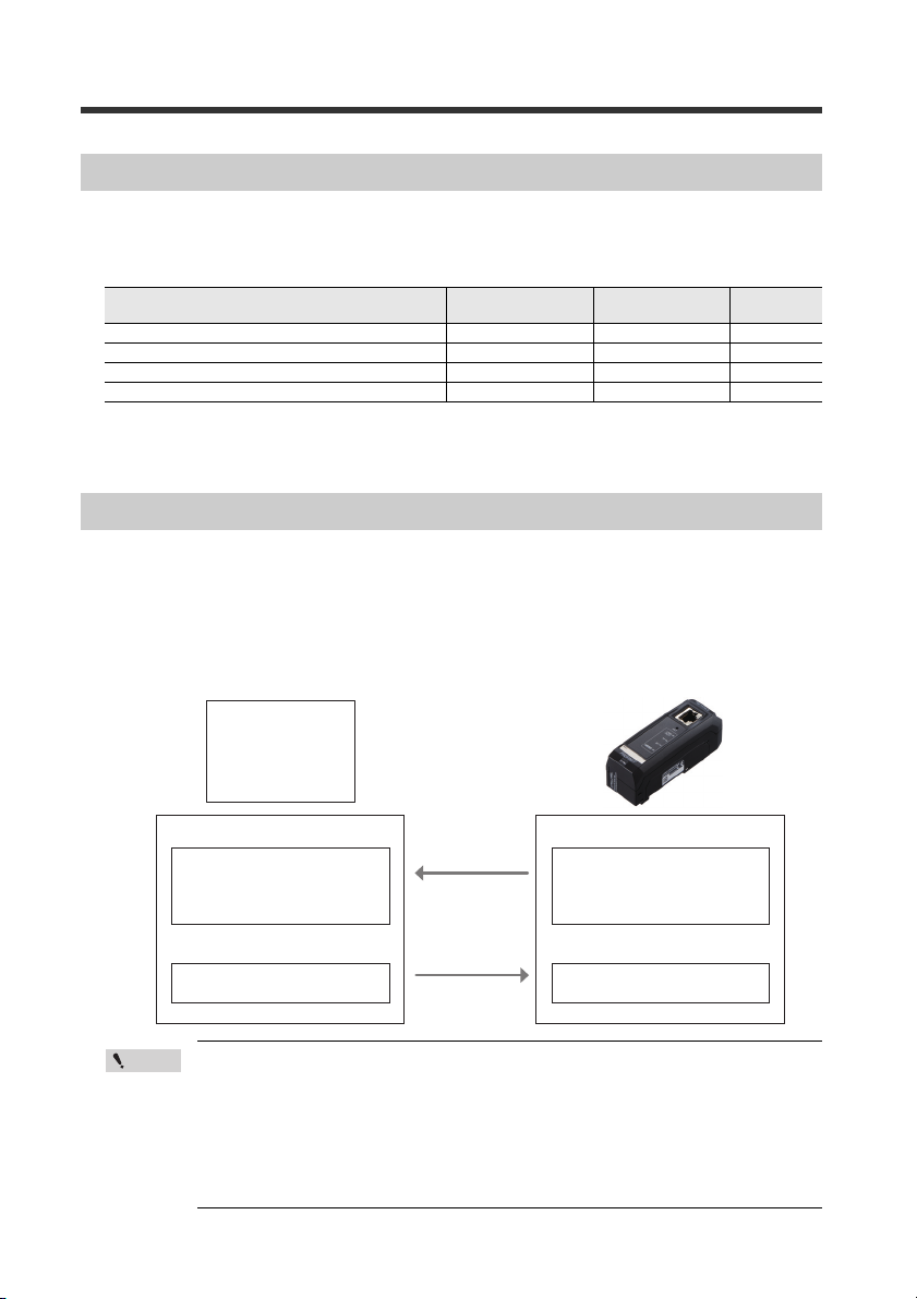
Point
Input Area
· Status result
· Control/status/error result
· Read comparator value
Output Area
· Execute external input
Output Area
Input Area
PROFINET
communication
I/O Controller
· Status result
· Control/status/error result
· Read comparator value
· Execute external input
Update time
(Communication
cycle)
DL-PN1 PROFINET Communication Overview
The DL-PN1 enables you to read or write various settings and conditions of the sensor
amplifier via PROFINET.
Examples are shown below.
Item
Reading the sensor amplifier control output 8
Executing the external input to the sensor amplifier 8
Reading the sensor amplifier comparator value 9
Changing the sensor amplifier setting value 14
Data I/O
Communication
Record Data
Communication
Reference
DL-PN1 PROFINET functions are specified in a GSDML file.
You can download the GSDML file from the KEYENCE website:
http://www.keyence.com
Data I/O Communication
What is data I/O communication?
This function enables cyclic (i.e. in fixed intervals) data communications with the
PROFINET devices. This function provides high-speed control with several to several
tens of milliseconds.
The communication can be controlled by referencing and updating the variables in the
PLC, making it easy to control the programs on the PLC side.
page
4
• Communication settings for the data I/O communication, such as
Update time (communication cycle) and the data size, will be
configured on the PLC side.
• In a network with many connected devices (including the PROFINET
devices), a network delay and/or packet loss may occur when there
is a heavy load on the network. Conduct a thorough verification
before the operation.
- PROFINET Communication Unit DL-PN1 User's Manual (IB) -
Page 7
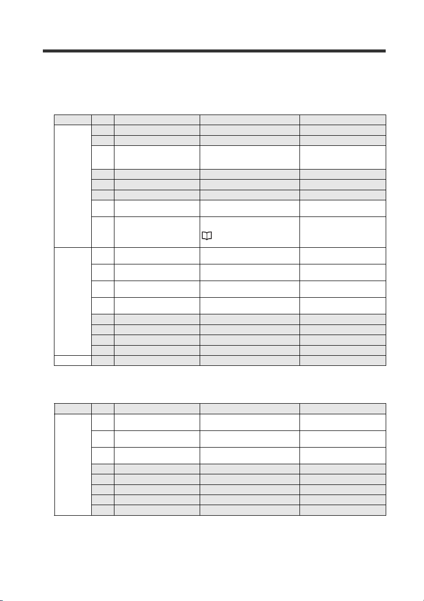
Data I/O communication device map (DL-PN1 PROFINET I/O controller)
DL-PN1 (Slot 0)
Input
Address Bit Function name Description Val ue
0 Reser ved for system - -
0
1
2 to 15
1 Reser ved for system - -
2 Comparator value property Stores the comparator value status.
3 Reser ved for system - -
4 Reser ved for system - -
5 Reser ved for system - -
6 Warning
7 Error status
0 External input response 1
1 External input response 2
2 External input response 3
3 External input response 4
4 Reser ved for system - -
5 Reser ved for system - -
6 Reser ved for system - -
7 Reser ved for system - -
0 to 7 Reserved for system - -
One of the sensor amplifiers is in
warning state.
Stores the error status of the sensor
amplifiers.
"Types of error and error code"
(page 29)
Stores the external input response
to the sensor amplifier.
Stores the external input response
to the sensor amplifier.
Stores the external input response
to the sensor amplifier.
Stores the external input response
to the sensor amplifier.
0: Normal
1: Disabled status
“----”, “FFFF”, or “-FFFF”
0: No warning
1: Warning
0: No error occurred.
1: Error occurred.
0: No input
1: Input reception
0: No input
1: Input reception
0: No input
1: Input reception
0: No input
1: Input reception
Sensor amplifier (Slot 1 to 4)
Input
Address Bit Function name Description Valu e
0 High
1Low
16+7(a-1)*
2Go
3 Reser ved for system - -
4 Reser ved for system - -
5 Reser ved for system - -
6 Reser ved for system - -
7 Reser ved for system - -
- PROFINET Communication Unit DL-PN1 User's Manual (IB) -
ON/OFF of the High state of the
sensor amplifiers is output.
ON/OFF of the Low state of the
sensor amplifiers is output.
ON/OFF of the Go state of the
sensor amplifiers is output.
0: OFF
1: ON
0: OFF
1: ON
0: OFF
1: ON
5
Page 8
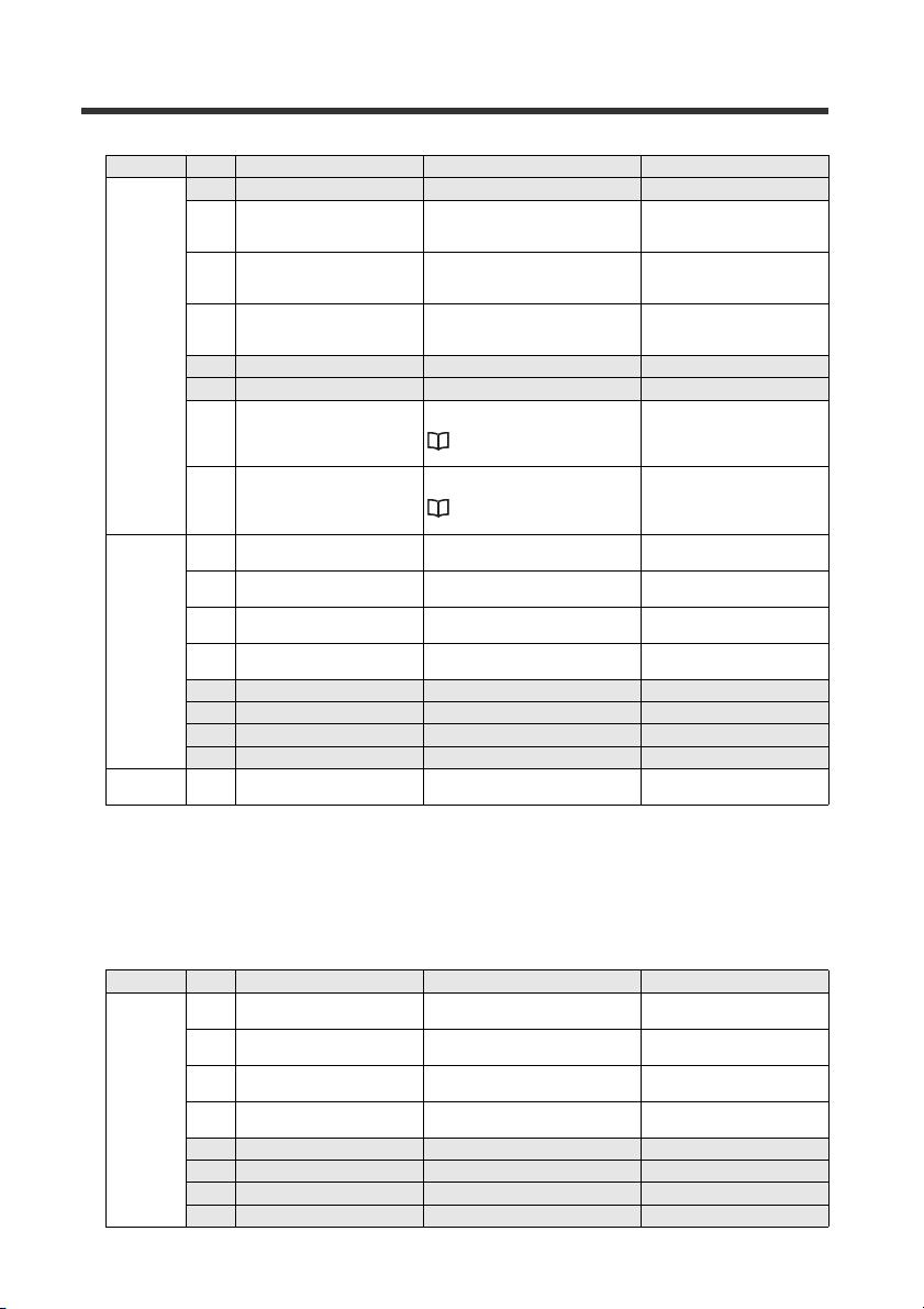
Address Bit Function name Description Va lue
17+7(a-1)*
18+7(a-1)*
19+7(a-1)* to
22+7(a-1)*
0 Reser ved for system - -
1 Comparator value invalid Stores the comparator value status.
2 Comparator value under range Stores the comparator value status.
3 Comparator value over range Stores the comparator value status.
4 Reser ved for system - -
5 Reser ved for system - -
6 Warning
7 Error status
0 External input response 1
1 External input response 2
2 External input response 3
3 External input response 4
4 Reser ved for system - -
5 Reser ved for system - -
6 Reser ved for system - -
7 Reser ved for system - -
0 to 7 Comparator value
Represents the warning status of the
sensor.
"Types of error and error code"
(page 29)
Stores the error status of the sensor
amplifiers.
"Types of error and error code"
(page 29)
Stores the external input response
to the sensor amplifier.
Stores the external input response
to the sensor amplifier.
Stores the external input response
to the sensor amplifier.
Stores the external input response
to the sensor amplifier.
Used when reading the comparator
value (P.V. value).
0: Normal
1: Comparator value invalid
“----”
0: Normal
1: Comparator value under
range “-FFFF”
0: Normal
1: Comparator value over
range “FFFF”
0: No warning
1: Warning
0: No error occurred.
1: Error occurred.
0: No input
1: Input reception
0: No input
1: Input reception
0: No input
1: Input reception
0: No input
1: Input reception
INT32
* "a" represents a Slot number. When Addresses were assigned in order, the Address
for Slot 1 is 16, 17, 18, or 19 to 22.
Data I/O communication device map (PROFINET I/O controller DL-PN1)
DL-PN1 (Slot 0)
Output
Address Bit Function name Description Valu e
0 External input request 1
1 External input request 2
2 External input request 3
0
6
3 External input request 4
4 Reserved for system - -
5 Reserved for system - -
6 Reserved for system - -
7 Reserved for system - -
- PROFINET Communication Unit DL-PN1 User's Manual (IB) -
Requests the external input to the
*1
sensor amplifiers.
Requests the external input to the
*1
sensor amplifiers.
Requests the external input to the
*1
sensor amplifiers.
Requests the external input to the
*1
sensor amplifiers.
0: OFF
1: ON
0: OFF
1: ON
0: OFF
1: ON
0: OFF
1: ON
Page 9
*1 External input request to the sensor amplifiers connected to the DL-PN1 (Slot 0) can
be executed en bloc. (Smart Access function)
Functions assigned to the external input request 1 to 4 are as follows:
• External input request 1: ZERO SHIFT input
• External input request 2: RESET input
• External input request 3: TIMING input
• External input request 4: Adjust input
Functions assigned to the external input request 1 to 4 can be changed.
Refer to the IB series user's manual.
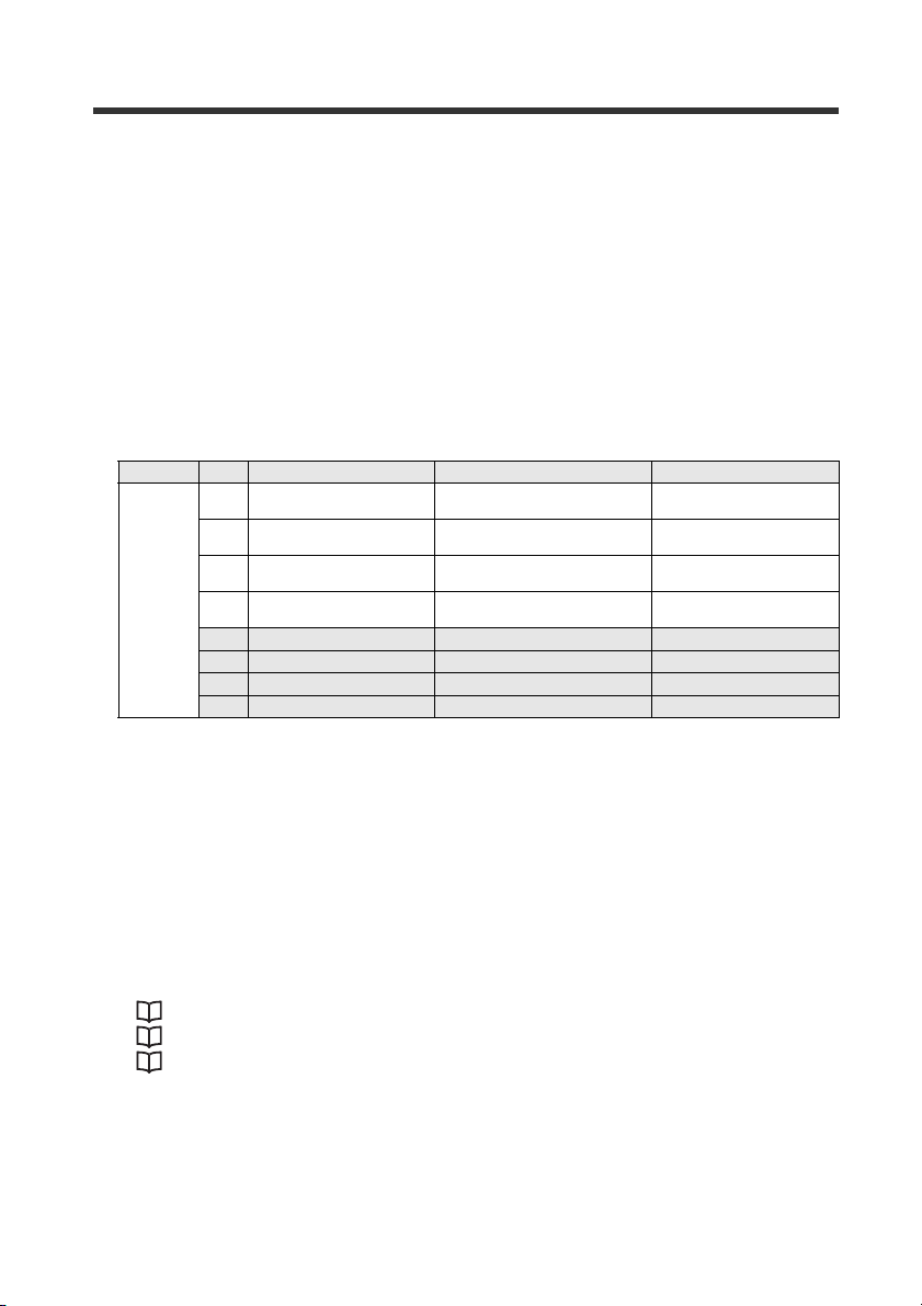
Sensor amplifier (Slot 1 to 4)
Output
Address Bit Function name Description Valu e
0 External input request 1
1 External input request 2
2 External input request 3
1 to 4
3 External input request 4
4 Reser ved for system - -
5 Reser ved for system - -
6 Reser ved for system - -
7 Reser ved for system - -
Functions assigned to the external input request 1 to 4 are as follows:
• External input request 1: ZERO SHIFT input
• External input request 2: RESET input
• External input request 3: TIMING input
• External input request 4: Adjust input
Functions assigned to the external input request 1 to 4 can be changed.
Refer to the IB series user's manual.
Requests the external input to the
sensor amplifiers.
Requests the external input to the
sensor amplifiers.
Requests the external input to the
sensor amplifiers.
Requests the external input to the
sensor amplifiers.
0: OFF
1: ON
0: OFF
1: ON
0: OFF
1: ON
0: OFF
1: ON
Communication Methods
The following describes how the I/O controller communicates with the DL-PN1 (data I/O
communication).
• "Reading an output from a sensor amplifier" (page 8)
• "Entering an external input to a sensor amplifier" (page 8)
• "Reading comparator values (P.V. values) from sensor amplifiers" (page 9)
- PROFINET Communication Unit DL-PN1 User's Manual (IB) -
7
Page 10
Output
High output of ID01
Sensor amplifier
Master
Slot 1
Bit 0 of the input address 16
1
0
ON
OFF
(1)
(2)
(1)
Master
External input request
External input response
Sensor amplifier
External input
TIMING input of ID01
1
0
ON
OFF
1
0
Slot 1
Bit 1 of the output address 1
Slot 1
Bit 1 of the input address 18
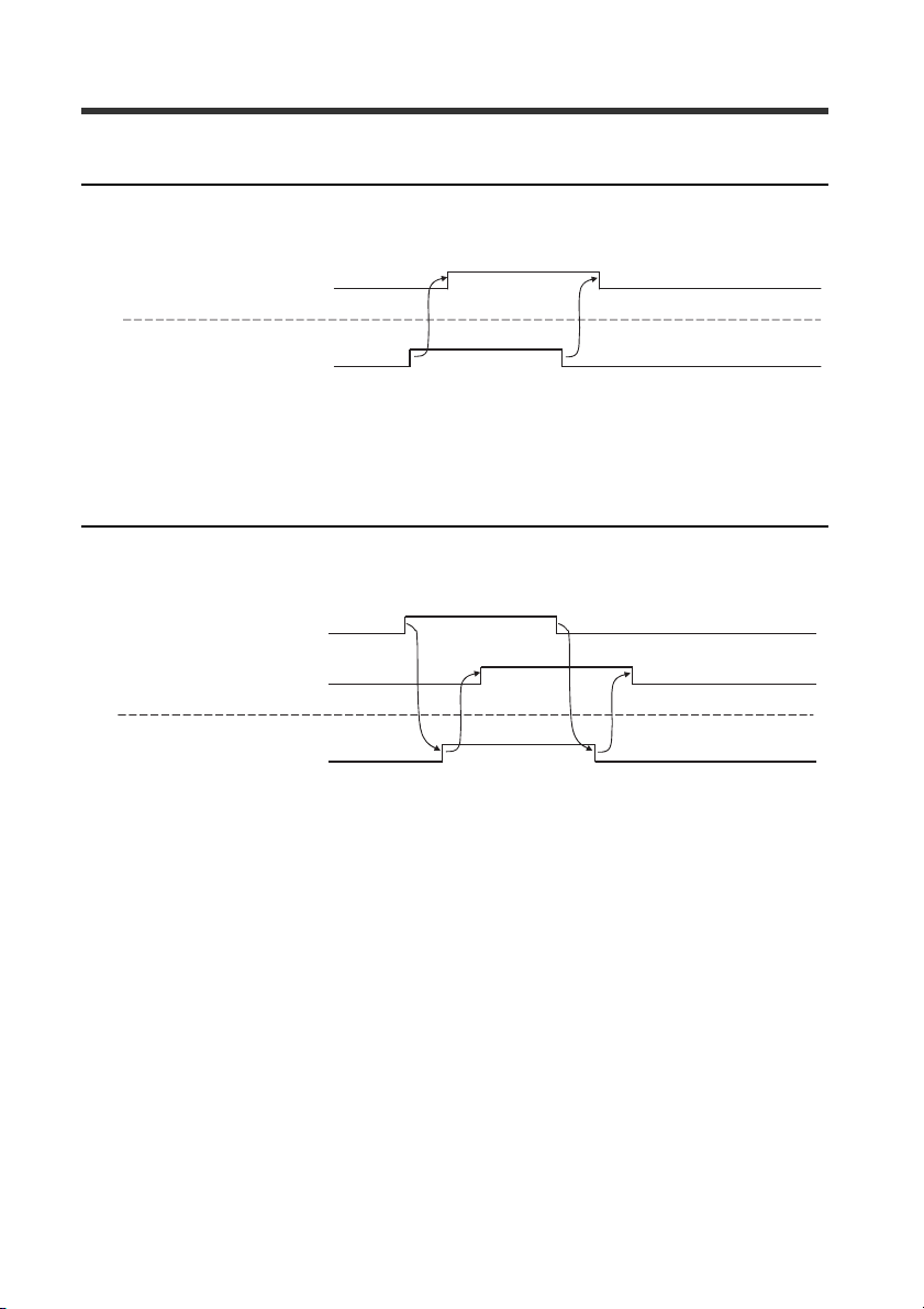
Reading an output from a sensor amplifier
Available outputs: High, Low, Go
This example shows how to read the High output from Slot 1 (ID01).
(1) The output from the sensor amplifier entered into Bit 0 of the input address 16 via
data I/O communication.
This example shows how to read the High output from the sensor amplifier ID01.
Entering an external input to a sensor amplifier
Available external inputs: PRESET, TIMING, RESET, error clear
This example shows how to enter the TIMING input from Slot 1 (ID01).
8
(1) The output address value to which an external input request was assigned is linked
via data I/O communication and the external input of the sensor amplifier is turned
on or off.
(2) You can check the input status of the sensor amplifier with the external input
response.
- PROFINET Communication Unit DL-PN1 User's Manual (IB) -
Page 11
Reading comparator values (P.V. values) from sensor amplifiers
(1)
Master
Comparator value under range
Input address 17/24/31 Bit 3 of Slot 1/2/3
Comparator value of ID 01
1234 4567 6789
Input address 19 to 22 (DEX) of Slot 1
Comparator value of ID 02
2345 5678 7890
Input address 26 to 29 (DEX) of Slot 2
Comparator value of ID 03
3456 8901
Input address 33 to 36 (DEX) of Slot 3
Sensor amplifier
Comparator value of ID 01
1234 4567 6789
Comparator value of ID 02
2345 5678 7890
Comparator value of ID 03
3456 8901
Comparator value over range
Input address 17/24/31 Bit 2 of Slot 1/2/3
Comparator value invalid
Input address 17/24/31 Bit 1 of Slot 1/2/3
1
1
1
0
0
0
(2)
(2)
(2)
This example shows how to read the comparator values (P.V.values) from the sensor
amplifiers ID01, ID02, and ID03.
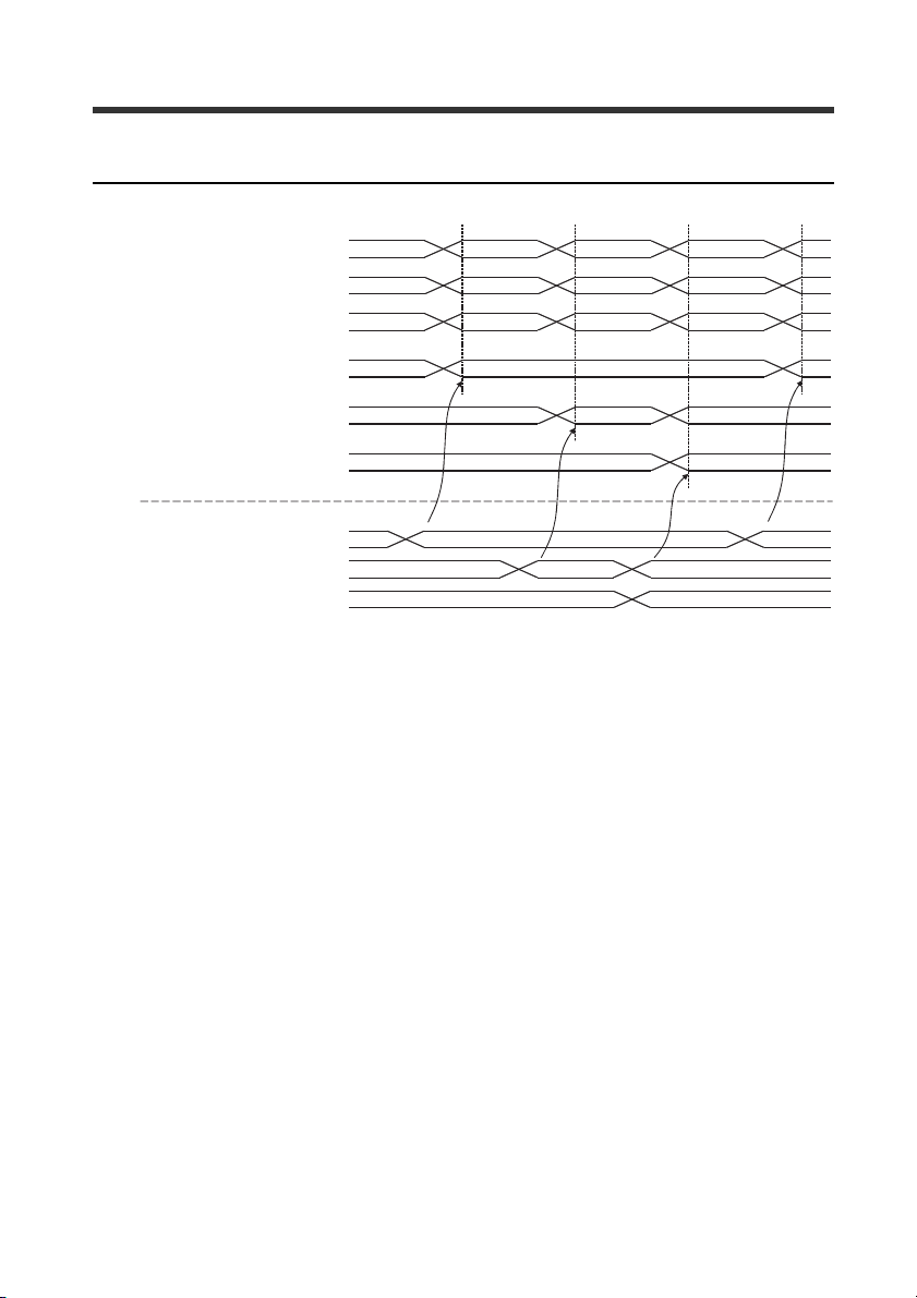
(1) When the comparator value of a sensor amplifier is updated, the value of the input
address is also updated via data I/O communication.
If the judgment value is correct, the parameter range is
- from - 999.99 to +999.99 (percent mode).
- from - 99.999 to +99.999 (size mode).
If the comparator value is over range, under range, or invalid, the previous value is
retained without updating the comparator value. To confirm whether the current
value is correct, use the comparator value property.
(2) The comparator value invalid, comparator value over range, or comparator value
under range is entered.
If the comparator value of a sensor amplifier is "invalid", "over", or "under", the bit
corresponding to the ID number of that sensor amplifier flips to 1.
- PROFINET Communication Unit DL-PN1 User's Manual (IB) -
9
Page 12

(1) Record data
communication command
(3) Record data
communication response
I/O controller Sensor amplifier
Send
Receive
Receive
Send
(2) Interpret and
execute command
DL-PN1
6)%
5HDGD3URFHVV'DWD5HFRUG
(1 5'5(& (1
5(4 9$/,'
,' %86<
,1'(; (5525
0/(1 67$786
5(&25' /(1
6)%
:ULWHD3URFHVV'DWD5HFRUG
(1
:55(&
(1
5(4 9$/,'
,' %86<
,1'(; (5525
0/(1 67$786
5(&25'
Record Data Communication
What is record data communication?
Record data communication is a function that performs communication by issuing
commands when desired. It is used for applications which do not require the punctuality
of data I/O communication, such as reading and writing I/O device settings.
Basic Format and Flow of Record Data Communication
Record data communication uses function block, which blocks circuits being used in a
program. For Siemens SIMATEC Manager / TIA Portal, use SFB52"RD REC" and
SFB53"WR REC".
SFB52"RD REC"
Reads data.
SFB53"WR REC"
Writes data.
10
Parameter name Description
EN Enables.
EN0 Shows that EN is enabled.
REQ Enables when making a request.
ID Enters the DL-PN1 or sensor amplifier ID number.
INDEX Enters the Access Address Index number.
MLEN Set to 4.
- PROFINET Communication Unit DL-PN1 User's Manual (IB) -
Page 13

Point
Parameter name Description
RECORD A value is input when reading. Inputs a value when writing.
VALID Replies as to whether the action was valid.
BUSY Replies as to whether the unit is busy.
ERROR Replies as to whether there is an error.
STATUS Replies with status information (including error information).
LEN Replies the length of the reply data.
To input the ID number for the DL-PN1 into ID, refer to the instruction
manual for each PLC. When inputting the ID number of the sensor
amplifier connected to the DL-PN1 into ID, input the smaller of the Slot
I Address and Q Address. If Q Address will be input, add
32768(0x8000).
Access Address (Slot 0)
Index
(DEC)
0Key lock
1Key unlock
2
3
4
5 Light emission stop cancel
6 to 14 Reserved for system
15 Initialization request
16 to 31 Reser ved for system
32 DL-PN1 error state
33
34 to 63 Reser ved for system
Function name Description
Power saving function
(ECO)
Power saving function
(ECO) cancel
Light emission stop
request
Number of connectable
units
The sensor amplifier enters
the key lock state.
The key lock of the sensor
amplifier is canceled.
The sensor amplifier enters
the eco mode.
The eco mode of the sensor
amplifier is canceled.
Light emission of the sensor
amplifier is stopped.
Light emission stop of the
sensor amplifier is canceled.
Initializes the sensor
amplifier.
Stores the DL-PN1 error
status.
"Types of error and error
code" (page 29)
Stores the number of sensor
amplifiers connected to the
DL-PN1.
Data
type
2byte
WORD
2byte
WORD
2byte
WORD
2byte
WORD
2byte
WORD
2byte
WORD
2byte
WORD
2byte
WORD
2byte
INT
Attribute
bit0 : Reserved for system
bit1 : Slot 1
W
bit15 : Slot 15
bit0 : Reserved for system
bit1 : Slot 1
W
bit15 : Slot 15
bit0 : Reserved for system
bit1 : Slot 1
W
bit15 : Slot 15
bit0 : Reserved for system
bit1 : Slot 1
W
bit15 : Slot 15
bit0 : Reserved for system
bit1 : Slot 1
W
bit15 : Slot 15
bit0 : Reserved for system
bit1 : Slot 1
W
bit15 : Slot 15
bit0 : Reserved for system
bit1 : Slot 1
W
bit15 : Slot 15
R
R0 to 15
Val ue
:
:
:
:
:
:
:
- PROFINET Communication Unit DL-PN1 User's Manual (IB) -
11
Page 14

Index
(DEC)
64 Error state
65 Warning status
66 Comparator value property
67
68
69 Comparator value Invalid
70 to 77 Reserved for system
78 Output 1
79 Output 2
80 Output 3
81 to 85 Reserved for system
86 External input response 1
87 External input response 2
88 External input response 3
89 External input response 4
90 to 95 Reserved for system
Function name Description
Comparator value over
range
Comparator value under
range
When the sensor amplifier is
in the error state, the
corresponding bit is set.
"Types of error and error
code" (page 29)
When the sensor amplifier is
in the warning state, the
corresponding bit is set.
"Types of error and error
code" (page 29)
When the sensor amplifier
comparator value is invalid or
exceeding the upper or lower
limit, the corresponding bit is set.
When the sensor amplifier
comparator value is
exceeding the upper limit, the
corresponding bit is set.
When the sensor amplifier
comparator value is
exceeding the lower limit, the
corresponding bit is set.
When the sensor amplifier
comparator value is invalid,
the corresponding bit is set.
When the control output of
sensor amplifier is High, the
corresponding bit is set.
When the control output of
sensor amplifier is Low, the
corresponding bit is set.
When the control output of
sensor amplifier is Go, the
corresponding bit is set.
When the request reception
to the "External input request
1" is complete, the
corresponding bit is set.
When the request reception
to the "External input request
2" is complete, the
corresponding bit is set.
When the request reception
to the "External input request
3" is complete, the
corresponding bit is set.
When the request reception
to the "External input request
4" is complete, the
corresponding bit is set.
*1
*1
*1
*1
Data
type
2byte
WORD
2byte
WORD
2byte
WORD
2byte
WORD
2byte
WORD
2byte
WORD
2byte
WORD
2byte
WORD
2byte
WORD
2byte
WORD
2byte
WORD
2byte
WORD
2byte
WORD
Attribute
bit0 : Reserved for system
bit1 : Slot 1
R
bit15 : Slot 15
bit0 : Reserved for system
bit1 : Slot 1
R
bit15 : Slot 15
bit0 : Reserved for system
bit1 : Slot 1
R
bit15 : Slot 15
bit0 : Reserved for system
bit1 : Slot 1
R
bit15 : Slot 15
bit0 : Reserved for system
bit1 : Slot 1
R
bit15 : Slot 15
bit0 : Reserved for system
bit1 : Slot 1
R
bit15 : Slot 15
bit0 : Reserved for system
bit1 : Slot 1
R
bit15 : Slot 15
bit0 : Reserved for system
bit1 : Slot 1
R
bit15 : Slot 15
bit0 : Reserved for system
bit1 : Slot 1
R
bit15 : Slot 15
bit0 : Reserved for system
bit1 : Slot 1
R
bit15 : Slot 15
bit0 : Reserved for system
bit1 : Slot 1
R
bit15 : Slot 15
bit0 : Reserved for system
bit1 : Slot 1
R
bit15 : Slot 15
bit0 : Reserved for system
bit1 : Slot 1
R
bit15 : Slot 15
Valu e
:
:
:
:
:
:
:
:
:
:
:
:
:
12
- PROFINET Communication Unit DL-PN1 User's Manual (IB) -
Page 15

Index
(DEC)
96
:: : ::
99
100 to
111
112
:: : ::
115
116 to
127
128 Product code 1
:: : ::
131 Product code 4
132 to
143
144 Revision 1
:: : :: :
147 Revision 4
148 to
159
160
:: : ::
163
164 to
175
176
:: : ::
179
Function name Description
1st Sensor Head 1
Identification
4th Sensor Head 1
Identification
Reserved for system
1st Sensor Head 2
Identification
4th Sensor Head 2
Identification
Reserved for system
Reserved for system
Reserved for system
Comparator value 0 (Slot
Number 1)
Comparator value 0 (Slot
Number 4)
Reserved for system
Number of decimal places
(Current value 0, Slot
Number 1)
Number of decimal places
(Current value 0, Slot
Number 4)
Stores the type of the slot
number 01 sensor head (light
transmitter).
Stores the type of the slot
number 04 sensor head (light
transmitter).
Stores the type of the slot number
01 sensor head (light receiver).
Stores the type of the slot number
04 sensor head (light receiver).
Stores the product code of
the slot number 01 sensor
amplifier.
Stores the product code of
the slot number 04 sensor
amplifier.
Stores the revision of the slot
number 01 sensor amplifier.
Stores the revision of the slot
number 04 sensor amplifier.
Used when reading the
comparator value (P.V. value)
of slot number 01.
Used when reading the
comparator value (P.V. value)
of slot number 04.
Used when reading the
decimal position of the slot
number 01 comparator value
(P.V. value).
Used when reading the
decimal position of the slot
number 04 comparator value
(P.V. value).
*2
*2
Data
type
4byte
DINT
4byte
DINT
4byte
DINT
4byte
DINT
2byte
WORD
2byte
WORD
2byte
WORD
2byte
WORD
4byte
DINT
4byte
DINT
4byte
DINT
4byte
DINT
Attribute
0: Sensor head is not
connected, or light
receiver is connected.
R
1: Light transmitter of IB-01
2: Light transmitter of IB-05
3: Light transmitter of IB-10
4: Light transmitter of IB-30
0: Sensor head is not
connected, or light
transmitter is connected.
R
1: Light receiver of IB-01
2: Light receiver of IB-05
3: Light receiver of IB-10
4: Light receiver of IB-30
R
R
R
R
R 0101H to FFFFH
R 0101H to FFFFH
R
In percent mode:
-999.99 to +999.99
In size mode:
-99.999 to +99.999
R
R
R
Val ue
- PROFINET Communication Unit DL-PN1 User's Manual (IB) -
13
Page 16

Index
(DEC)
180 to
191
192 Setting error
193 EEPROM writing
194 Laser emission stop status
Function name Description
Reserved for system
When the sensor amplifier
setting is abnormal, the
corresponding bit is set.
When the sensor amplifier is
reflecting the setting after the
setting change, the
corresponding bit is set.
When the light emission of
the sensor amplifier stops,
the corresponding bit is set.
Data
type
2byte
WORD
2byte
WORD
2byte
WORD
Attribute
bit0 : Reserved for system
bit1 : Slot 1
R
bit15 : Slot 15
bit0 : Reserved for system
bit1 : Slot 1
R
bit15 : Slot 15
bit0 : Reserved for system
bit1 : Slot 1
R
bit15 : Slot 15
*1 Functions assigned to the external input request 1 to 4 are as follows:
• External input request 1: ZERO SHIFT input
• External input request 2: RESET input
• External input request 3: TIMING input
• External input request 4: ADJUST input
Functions assigned to the external input request 1 to 4 can be changed.
Refer to the IB series user's manual.
*2 If the judgment value is correct, the parameter range is
- from - 999.97 to +999.98 (percent mode).
- from - 99.997 to +99.998 (size mode).
In percent mode:
• When the comparator value is over range, "+999.99" is stored.
• When the comparator value is under range, "-999.99" is stored.
• When the comparator value is invalid, "-999.98" is stored.
• When an error occurs, "+1000.00" is stored.
In size mode:
• When the comparator value is over range, "+99.999" is stored.
• When the comparator value is under range, "-99.999" is stored.
• When the comparator value is invalid, "-99.998" is stored.
• When an error occurs, "+100.000" is stored.
Valu e
:
:
:
Access Address (Slot 1 to 4)
Index
(DEC)
0 Reserved for system
1 Zero shift request DINT C
2 Zero shift reset request DINT C
3 Reset request DINT C
4 Error clear request DINT C
5 Initial reset request DINT C
6
7 to 9 Reserved for system
14
Function name
System parameter set request
Description
- PROFINET Communication Unit DL-PN1 User's Manual (IB) -
Data
Attribute
type
DINT C
Default
value
Valu e
Page 17

Index
(DEC)
10
11 Adjust request DINT C
12 Adjust reset request DINT C
13 Reserved for system
14 Tolerance tuning request D INT C
15
16
17
18
19
20
21 to 25 Reserved for system
26 Logical correction 1st request DINT C
27
28 to 31 Reserved for system
32 Group1 Entry Count DINT R 29
33 Error status *1 DINT R
34
35
36
37
38
Function name
Reference light registration request
Two-point turning HIGH side
1st request
Two-point turning HIGH side
2nd request
Two-point turning LOW side
1st request
Two-point turning LOW side
2nd request
Measured correction 1st
request
Measured correction 2nd
request
Logical correction 2nd request
Warning status
Warning function operating
state
Judgment output/Check
output
Current value (P.V. value)
Raw value (R.V. Value)
Description
Data
Attribute
type
DINT C
DINT C
DINT C
DINT C
DINT C
DINT C
DINT C
DINT C
DINT R
DINT R
*2
DINT R
*20
*3
DINT R -999.99 to +999.99
*4
*4 DINT R -999.99 to +999.99
Default
value
Val ue
Bit0: Overcurrent error (ErC)
Bit1: EEPROM error (ErE)
Bit2: Sensor head error
Bit3: Transmitter/Receiver
reverse connection
error
Bit4: Transmitter internal
error
Bit5: Receiver error
Bit6: Transmitter error
Bit7: Transmitter laser error
Bit8: Model mismatch error
Bit9: Reference light
registration error
Bit10: Adjust error
Bit11: Amplifier
communication error
0: Check output OFF
1: Check output ON (i n N.O.)
0:
Check output function disabled
1: Check output function enabled
Bit0:
HIGH judgment output
0: OFF, 1: ON
Bit1: LOW judgment output
0: OFF, 1: ON
Bit2: GO judgment output
0: OFF, 1: ON
Bit3: Check output
0: OFF, 1: ON
- PROFINET Communication Unit DL-PN1 User's Manual (IB) -
15
Page 18

Index
(DEC)
39
40
41 Reserved for system
42 Analog output value *8 DINT R
43 Bank status DINT R
44 Timing status DINT R
45 to 49 Reserved for system
50 Laser emission stop status DINT R
51 Abnormal setting *9 DINT R
52 External input status *21 DINT R 0 to 15
53 EEPROM writing result *10 DINT R 1
54 Zero shift executing result *11 DINT R 1
55 Reset execution result *11 DINT R 1
56
57 Reserved for system
58
59 Adjust result DINT R 1
60 Tuning result *13 DINT R 1
61 Correction result *22 DINT R 1
62 to 63 Reserved for system
Function name
Peak-hold value in hold mode
Bottom-hold value in hold
mode
System parameter current
state
Reference light registration
result
Description
Data
Attribute
type
*4
*5
DINT R -999.99 to +999.99
*7
*4
*6
DINT R -999.99 to +999.99
*7
*12 DINT R 0
DINT R 1
Default
value
Valu e
Analog voltage output:
-5.000 to +5.000
Analog current output:
+04.00 to +20.00
0: Bank 0
1: Bank 1
2: Bank 2
3: Bank 3
0: During Sampling
1: Not during sampling
0: Laser emitting
1: Laser stopped
0: Normal setting
1: Abnor mal setting
0: Writing
1: Normal ter mination
2: Abnormal termination
0: Executing
1: Normal ter mination
2: Execution impossible
0: Executing
1: Normal ter mination
2: Execution impossible
Main unit: 0 to 9
Expansion unit: 0 to 1
0: Executing
1: Normal ter mination
2:
Reference light registration error
1 (Light insufficient error)
3: Reference light registration
error 2 (Interfering light error)
0: Executing
1: Normal ter mination
2: Adjust error 1 (Light
insufficient error)
3: Adjust error 2 (Interfering
light error)
4:
Adjust error 3 (Excess light error)
0: Executing
1: Normal ter mination
2: Execution impossible
0: Executing
1: Normal ter mination
2: Execution impossible
16
- PROFINET Communication Unit DL-PN1 User's Manual (IB) -
Page 19

Index
(DEC)
64 Group2 Entry count DINT R 12
65 HIGH setting value (BANK 0) *7 DINT R/W +20.00 -999.99 to +999.99
66 LOW setting value (BANK 0) *7 DINT R/W +10.00 -999.99 to +999.99
67 Shift target value (BANK 0) *7 DINT R/W 0.00 -999.99 to +999.99
68 HIGH setting value (BANK 1) *7 DINT R/W +20.00 -999.99 to +999.99
69 LOW setting value (BANK 1) *7 DINT R/W +10.00 -999.99 to +999.99
70 Shift target value (BANK 1) *7 DINT R/W 0.00 -999.99 to +999.99
71 HIGH setting value (BANK 2) *7 DINT R/W +20.00 -999.99 to +999.99
72 LOW setting value (BANK 2) *7 DINT R/W +10.00 -999.99 to +999.99
73 Shift target value (BANK 2) *7 DINT R/W 0.00 -999.99 to +999.99
74 HIGH setting value (BANK 3) *7 DINT R/W +20.00 -999.99 to +999.99
75 LOW setting value (BANK 3) *7 DINT R/W +10.00 -999.99 to +999.99
76 Shift target value (BANK 3) *7 DINT R/W 0.00 -999.99 to +999.99
77 to 95 Reserved for system
96 Group3 Entry Count DINT R 20
97 Key lock setting DINT R/W 0
98 Bank setting *14 DINT R/W 0
99 Timing input *15 DINT R/W 0
100 Laser emission stop input *15 DINT R/W 0
101 to
103
104 Sub display's screen DINT R/W 0
105 System parameter *12 DINT R/W 0
106 Tolerance tuning setting width *16 DINT R/W 10.00 0.00 to 999.99
107 Calibration function DINT R/W 0
108
109
110 to
114
115
116
117 to
127
128 Group4 Entry count DINT R 30
129 Reserved for system
Function name
Reserved for system
Measured/Logical correction
target 1
Measured/Logical correction
target 2
Reserved for system
Logical correction measured 1
Logical correction measured 2
Reserved for system
Description
Data
Attribute
type
*7 DINT R/W 0.00 -999.99 to +999.99
*7 DINT R/W +100.00 -999.99 to +999.99
*7 DINT R/W 0.00 -999.99 to +999.99
*7 DINT R/W +100.00 -999.99 to +999.99
Default
value
0: Release
1: Key lock
0: Switched to bank 0
1: Switched to bank 1
2: Switched to bank 2
3: Switched to bank 3
0: Timing i nput OFF
1: Timing i nput ON
0: Emission stop input OFF
1: Emission stop input ON
0: R.V. value screen
1: Analog value screen
2: HIGH setting value screen
3: LOW setting value screen
4: Shift target value setting
screen
Main unit: 0 to 9
Expansion unit: 0 to 1
0: No correction (Default)
1: Measured correction
2: Logical correction
Val ue
- PROFINET Communication Unit DL-PN1 User's Manual (IB) -
17
Page 20

Index
(DEC)
130 Measurement mode DINT R/W 0
131 Received/Blocked light mode DINT R/W 0
132 Reserved for system
133 Averaging/High-pass filter DINT R/W 5
134 Output mode DINT R/W 0
135 Reserved for system
136 Hold function setting DINT R/W 0
137 Auto hold trigger level *7 DINT R/W +90.00 -999.99 to +999.99
138 Timing input setting DINT R/W 0
139 Delay Timer DINT R/W 0
140 Timer duration DINT R/W 60 1 to 9999
141 Hysteresis DINT R/W 0.00 0.00 to 999.99
142 Analog output scaling
143 Analog output upper limit
144 Analog output lower limit
145 External input setting *18 DINT R/W 0
Function name
Description
Data
Attribute
type
*17
DINT R/W 0
*19
*7
*17
DINT R/W +100.00 -999.99 to +999.99
*19
*7
*17
DINT R/W 0 -999.99 to +999.99
*19
Default
value
Valu e
0: Percent mode
1: Dimension mode
0: Received light mode
1: Blocked light mode
Averaging
0: 1 time
1: 2 times
2: 4 times
3: 8 times
4: 16 times
5: 64 times
6: 256 times
7: 1024 times
8: 4096 times
9: 16384 times
High-pass filter
10: 0.1Hz
11: 0.2Hz
12: 0.5Hz
13: 1Hz
14: 2Hz
15: 5Hz
16: 10Hz
17: 20Hz
18: 50Hz
19: 100Hz
0: N.O (Normal open)
1: N.C (Normal close)
0: Sample hold
1: Peak hold
2: Bottom hold
3: Peak-to-peak hold
4: Auto peak hold
5: Auto bottom hold
0: Level
1: Edge
0: OFF
1: On delay
2: Off delay
3: One-shot
0: Initial state
1: Free range
0: Default
1: User setting
18
- PROFINET Communication Unit DL-PN1 User's Manual (IB) -
Page 21

Index
(DEC)
146
147
148
149
150 Bank switching method DINT R/W 0
151 Reserved for system
152
153 Reserved for system
154
155 Power save function DINT R/W 0
156 Reserved for system
157 Judgment indicator color DINT R/W 0
158 P.V. value display color DINT R/W 0
159 Reserved for system
160 Group5 Entry count DINT R 9
161 Save adjust state DINT R/W 0
162 Adjust level DINT R/W 20 1 to 30
163 Auto adjust function DINT R/W 0
164 Auto adjust level DINT R/W 3.00 0.50 to 20.00
165 Check output function DINT R/W 0
166 Check output light level DINT R/W 10 1 to 30
Function name
External input 1 function
selection
External input 2 function
selection
External input 3 function
selection
External input 4 function
selection
Zero shift value memory
function
Display digit
Description
Data
Attribute
type
*18 DINT R/W 0
*18 DINT R/W 0
*18 DINT R/W 0
*18 DINT R/W 4
DINT R/W 0
DINT R/W 0
Default
value
0: Zero shift input
1: Bank A input
2: Bank B input
3: Laser emi ssion stop input
4: Not used
0: Reset input
1: Bank A input
2: Bank B input
3: Laser emi ssion stop input
4: Not used
0: Timing i nput
1: Bank A input
2: Bank B input
3: Laser emi ssion stop input
4: Not used
0: Adjust input
1: Bank A input
2: Bank B input
3: Laser emi ssion stop input
4: Not used
0: Button
1: External input
0: OFF
1: ON
0: Default
1: 0.0001
2: 0.001
3: 0.01
4: 0.1
5: 1
0: OFF
1: Half
2: All
0: Green for GO only (Default)
1: Red for Go only
2: All green
3: All red
0: Green for GO only (Default)
1: Red for Go only
2: All green
3: All red
0: OFF
1: ON
0: Disabled
1: Enabled
0: Disabled
1: Enabled
Val ue
- PROFINET Communication Unit DL-PN1 User's Manual (IB) -
19
Page 22

Index
(DEC)
167 Error output mode DINT R/W 0
168 Hysteresis for trigger level DINT R/W 0
169
170 to
191
192 Group6 Entry count DINT R 11
193 Product code DINT R
194 Reserved for system
195 Transmitter head model DINT R
196 Receiver head model DINT R
197 to
199
200 Product name 1 *20
201 Product name 2 *20
202 Product name 3 *20
203 Product name 4 *20
204 to
217
218 Unit
219 to
223
Function name
Hysteresis set value for
trigger level
Reserved for system
Reserved for system
Reserved for system
Reserved for system
Description
Data
Attribute
type
*16 DINT R/W 1.00 0.00 to 999.99
DINT/
STRING
DINT/
STRING
DINT/
STRING
DINT/
STRING
Default
value
0: Normal mode (Default)
1: LX2 compatible mode
0: Default
1: User setting
Main unit:=4020
Expansion unit:=4021
0:
Sensor head is not connected,
or light receiver is connected.
1: Light transmitter of IB-01 is
connected.
2: Light transmitter of IB-05 is
connected.
3: Light transmitter of IB-10 is
connected.
4: Light transmitter of IB-30 is
connected.
0:
Sensor head is not connected,
or light transmitter is connected.
1: Light receiver of IB-01 is
connected.
2: Light receiver of IB-05 is
connected.
3: Light receiver of IB-10 is
connected.
4: Light receiver of IB-30 is
connected.
R
R
R
R
Main unit:="IB-1"
Expansion unit:="IB-1"
Main unit:="000/"
Expansion unit:="050/"
Main unit:="1500"
Expansion unit:="1550"
Main unit:=""
Expansion unit:=""
Valu e
*1 The error content of the sensor amplifier can be checked by noting the ON/OFF
state of each bit.
OFF (0): No error; ON (1): Error
More than one error may occur simultaneously. For details of each error, refer to the
IB Series User's Manual.
*2 Details of output status can be checked by noting the ON/OFF state of each bit.
20
- PROFINET Communication Unit DL-PN1 User's Manual (IB) -
Page 23

*3 If the judgment value is correct, the parameter range is
from - 999.97 to +999.98 (percent mode).
from - 99.997 to +99.998 (size mode).
If the current value is over range, under range, or invalid, the previous value is retained
without updating the current value. Use the value with the judgment value property.
*4 If the read data has one of the values listed below, it has a different meaning than
the judgment value.
In % mode:
+999.99: The value is above the upper limit of the display range.
-999.99: The value is -999.98 or below the lower limit of the display range.
-999.98: The value is "-----" (invalid).
+1000.00: The sensor amplifier is in error.
In size mode:
+99.999: The value is above the upper limit of the display range.
-99.999: The value is -99.998 or below the lower limit of the display range.
-99.998: The value is "-----" (invalid).
+100.000: The sensor amplifier is in error.
*5 When in sample hold:
Value "-99.998" is output.
When not in sample hold:
The peak value encountered during the sampling period is output.
*6
When in sample hold:
Value "-99.998" is output.
When not in sample hold:
The bottom value encountered during the sampling period is output.
*7 When reading data from an amplifier unit in which the measurement mode is to "size
mode", the data format changes to "±**.***" (the read range is -99.999 to +99.999").
*8 If the sensor amplifier is in error, the analog voltage output is +5.500 and the analog
current output is +03.00.
*9 If a prohibited combination of functions is written, it results in "abnormal setting (1)"
For details of each function, refer to the IB Series User's Manual.
- PROFINET Communication Unit DL-PN1 User's Manual (IB) -
21
Page 24

Reference
Bit 0: NPN output
011
Bit 3, 2, 1: 1 to 5 V
0
*10 The result of the "initial reset request" motion command is included in this item.
Regarding Data No. 53 (EEPROM writing result), a "0: writing in progress" status is
maintained for 2 seconds after completion of the final write command transmission
to the nonvolatile memory (EEPROM). Writing begins 2 seconds later, and if
completed normally, the result is "1: successfully completed".
Example:
After every-second write command transmissions, a "0: writing in progress" status is
established for 2 seconds. A "0: writing in progress" status is maintained for 2
seconds after completion of the final write command transmission, and writing then
begins 2 seconds later, with a result of "1: successfully completed".
However, writing begins immediately following a initial reset executed in response to
a Data No. 5 "initial reset request". A "1: successfully completed" result then occurs
if all parameters have been saved to the nonvolatile memory (EEPROM)
approximately 3 seconds later.
• When "zero shift status save" is ON, writing begins immediately for Data No. 1
"zero shift request" and Data No. 2 "zero shift reset request".
• When the "adjust status save" function is ON, writing begins immediately for Data
No. 11 "adjust request" and Data No. 12 "adjust reset request".
• Writing also begins immediately for Data No. 12 "reference light intensity
registration request", Data No. 20 "measured correction target 2 request", and
Data No. 27 "logical correction target 2 request".
*11 The command reads the execution result of the "zero shift request" or "zero shift
reset request" whichever was last issued.
*12 By reading the "system parameter current state," the system parameters of the
sensor amplifier can be checked. The system parameters are comprised of the
settings of "judgment output/check output" polarity and analog output.
The "system parameter" attribute specifies the system parameters which are set
when the "system parameter set request" is executed by a motion command.
The values to be read or written are specified by translating them to binaries and
using ON or OFF in each bit of the binaries.
Bit Setting details
0: NPN output
0
1: PNP output
000: Analog output OFF
3, 2, 1
001: 0 to 5V
010: -5 to +5V
011: 1 to 5V
100: 4 to 20mA
Assume the read data is "006":
Translating "6" to a binary number gives "0110".
22
Thus, the sensor amplifier from which the data was read is set to "NPN
output" and "analog output 1 to 5 V".
- PROFINET Communication Unit DL-PN1 User's Manual (IB) -
Page 25

*13 This command reads the execution result of the "tolerance tuning request", "2-point
Reference
Reference
0110
External input 4: OFF
External input 3: ON
External input 1: OFF
External input 2: ON
tuning HIGH side 2nd request", or "2-point tuning LOW side 2nd request" motion
command whichever was last issued.
*14 This parameter works if "Bank switching method" is set to "button."
*15 These parameters are OFF only if data "0" is written and the wiring is configured to
turn off external input.
*16 When reading data from an amplifier unit in which the measurement mode is to
"dimension mode", the read range changes to "**.***" (0.000 to 99.999).
*17 A write control error results if data is rewritten to an expansion unit.
*18 To have the sensor amplifier reflect the settings written in data numbers 146 to 149,
it is necessary to set data number 145 to "1" (user setting), or to set the external
input to "user setting" via button operation on the sensor amplifier.
*19 An attempt to write this data results in an error. (Reading is results in "0.")
*20 The read value of the two-digit value can be translated to a binary number, so that
the ON/OFF state of each bit can be noted to know the status of judgment output
and check output.
Bit
0: HIGH judgment output OFF
0
1: HIGH judgment output ON
0: LOW judgment output OFF
1
1: LOW judgment output ON
0: GO judgment output OFF
2
1: GO judgment output ON
0: Check output OFF
3
1: Check output ON
N.O. mode N.C. mode
Judgment output
0: HIGH judgment output ON
1: HIGH judgment output OFF
0: LOW judgment output ON
1: LOW judgment output OFF
0: GO judgment output ON
1: GO judgment output OFF
0: Check output ON
1: Check output OFF
Assume the read data is "05":
Translating "05" to a binary number gives "0101".
N.O. mode
*21 The external input status is "1" when the external input is ON, and is "0" when the
*22 The result of "measured correction" and "logical correction" can be checked. This
0101
Bit 3: Alarm output OFF
Bit 2: GO judgment output ON
Bit 0: HIGH judgment output ON
Bit 1: LOW judgment output OFF
external input is OFF. Bits 0, 1, 2, and 3 correspond to external inputs 1, 2, 3, and 4,
respectively.
Assume the read data is "06":
Translating "6" to a binary number gives "0110".
data is not available if "calibration function" is set to "no correction."
- PROFINET Communication Unit DL-PN1 User's Manual (IB) -
23
Page 26

Appendix
Specifications
The specifications of the DL-PN1 are as follows:
Product name PROFINET I/O Communication Unit
Model DL-PN1
Suitable network PROFINET I/O communication
Compliant standards IEEE 802.3u (100BASE-TX)
Ethernet
PROFINET
Sensor connection
specifications
Power consumption 1500 mW or less (at 30 V 50 mA max.)
Environmental
resistance
Transmission rate 100 Mbps (100BASE-TX)
Transmission medium STP cable or Category 5e or higher UTP cable (100BASE-TX)
Maximum cable length 100 m
Compatible functions
No. of connectable
PROFINET I/O controllers
Update Time 2 - 512 ms
GSDML version V2.3
Conformance class Conforms with Conformance Class A
Conformance test version Conforms with V2.2.4
Suitable protocols LLDP, DCP
Connectable sensors Sensor amplifiers with D-bus suppor t
Number of connectable
sensor units
Indicator lamps
Power volta ge
Operating ambient air
temperature
Operating ambient air
humidity
Vibration resistance
Pollution degree 2
Materials Main unit: Polycarbonate
Weight Approx. 70 g
Data I/O communication
Record data communication
1
4 units max.
Link/activity indicator (LINK/ACT): Green LED
System failure indicator (SF): 2-color (orange/red) LED
Bus failure indicator (BF): Red LED
Sensor communication indicator (D-bus): 2-color (green/red) LED
20 to 30 V DC, including ripple (p-p)10%
supplied from the connected sensor amplifiers
-20 to +55°C (no freezing)
35 to 85% RH (no condensation)
10 to 55 Hz compound amplitude 1.5 mm, 2 hours each in X, Y, Z
directions
24
- PROFINET Communication Unit DL-PN1 User's Manual (IB) -
Page 27

Dimensions
25.6
35.443.5
94.5
38.1
(42.5 )
29.4
(Unit : mm)
- PROFINET Communication Unit DL-PN1 User's Manual (IB) -
25
Page 28

(4)(3)(2)(1)
DL-PN1
LINK
/ACT
RST
SF
BF
DL
Sensor amplifier
master
Data Processing Time
The data update time for data I/O communication is shown below.
Maximum data processing time = (1) + (2) + (3) + (4)
(1) I/O controller data update time
(2) Network data update time
(3) Data update time between the DL-PN1 and sensor amplifiers
Number of connected sensor
amplifiers
17.8 ms
29.8 ms
313.8 ms
415.8 ms
(4) Sensor amplifier response time
Output, judgment value, or current
value
For (1) and (2), see manuals for each model.
For (4), refer to the User's Manual of each sensor amplifier connected to the DL-PN1.
26
- PROFINET Communication Unit DL-PN1 User's Manual (IB) -
Page 29

Troubleshooting
Link/activity indicator (Green)
System Failure indicator (Orange, Red)
Bus Failure indicator (Red)
Sensor communication indicator (Green, Red)
The indicator LEDs on the DL-PN1 can be used to determine the causes of errors.
Link/activity indicator (LINK/ACT)
This indicator indicates whether the DL-PN1 is communicating correctly.
LED Status Condition Corrective Action
Solid The DL-PN1 is normally linked. -
Green
Flashing
Not lit
System Failure indicator (SF)
This indicator indicates whether the DL-PN1 is operating normally.
LED Status Condition Corrective Action
Solid red
Flashing orange
Not lit The DL-PN1 is normally operating. -
The DL-PN1 is normally linked and is
now exchanging data.
Power is not supplied to the DL-PN1.
The DL-PN1 is not linked.
There may be a system error on the
DL-PN1 or a connected sensor.
Flash LED was requested on the I/O
controller.
Flashes approximately 4 times per
second.
-
• Check if the power supply is correctly connected.
• Check if the DL-PN1 is correctly connected to the
sensor amplifier.
• Check if the IP address is correct.
• Check if the power supply of the connected device
or Ethernet switch is correctly connected.
• Check if the cable is correctly connected.
• Check the D-bus LED status.
• Check if the number of connected sensor
amplifiers exceeds the maximum number of
connectable units.
• Check if the IP address is correct.
• Check if the slot number is correct.
• Check if the DL-PN1 is correctly connected to the
sensor amplifier.
• Check if there is an electrical noise source near the
DL-PN1.
-
- PROFINET Communication Unit DL-PN1 User's Manual (IB) -
27
Page 30

Bus Failure indicator (BF)
This indicator indicates whether the DL-PN1 is communicating correctly with PROFINET.
LED Status Condition Corrective Action
Solid red
Not lit The DL-PN1 is normally operating. -
Data exchange via data I/O
communication is not being carried out
normally.
• Check if the number of connected sensor
amplifiers exceeds the maximum number of
connectable units.
• Check if the IP address is correct.
• Check if the slot number is correct.
• Check if the DL-PN1 is correctly connected to the
sensor amplifier.
• Check if there is an electrical noise source near the
DL-PN1.
Sensor communication indicator (D-bus)
This indicator indicates whether the DL-PN1 is communicating correctly with the sensor
amplifier.
If an error occurs, you can identify the cause of the error by reading the error code via
cyclic communication or message communication.
"Error code list" (page 29)
LED Status Condition Corrective Action
Solid green
Flashing
green
Solid red
Flashing red
(Repetition of
4 consecutive
flashes)
Flashing red
(Flashing at
fixed
intervals)
Not lit Power is not supplied to the DL-PN1.
The DL-PN1 is communicating correctly with
the sensor amplifier.
After power-on, the DL-PN1 is now starting up.
The DL-PN1 could not communicate with the
sensor amplifier during its start-up.
(Error code: 00H/52 or 00H/55)
An attempt to assign an ID number has failed.
(Error code: 00H/51)
The DL-PN1 could not communicate
continuously with the sensor amplifier for one
second or longer.
(Error code: 00H/57)
A system error may have occurred in the
DL-PN1.
A current limitation error occurred.
(Error code: 00H/56)
An unsupported sensor amplifier was
connected.
(Error code: 00H/53)
Unconnectable models are mixed.
(Error code: 00H/54)
Sometimes the DL-PN1 cannot temporarily
communicate with the sensor amplifier.
(Error code: 00H/57)
-
After it has started up, the DL-PN1 automatically shifts
to the normal status.
• Check if the DL-PN1 is correctly connected to the
sensor amplifier and turn on the power again.
• Check if an unsupported sensor am plifier is
connected to the DL-PN1 and turn on the power
again.
• Check if the number of connected sensor amplifiers
exceeds the maximum number of connectable units.
• Check if there is an electrical noise source around
the DL-PN1.
• If the error cannot be recovered after checking the
above, contact your nearest Keyence office.
Check the sensor amplifier configuration.
Check if there is an electrical noise source around the
DL-PN1. (The error is automatically reset if the cause is
removed.)
• Check if the DL-PN1 is correctly connected to the
sensor amplifier.
• Check if the power supply is correctly connected.
28
- PROFINET Communication Unit DL-PN1 User's Manual (IB) -
Page 31

Types of error and error code
Error code list
The following error codes may occur in the DL-PN1.
DL-PN1
Error code Description Cause Actions
0 No error -
51 Unassigned ID error
Start-time
52
communication error
Unsupported sensor
53
amplifier connection
error
54 Mixed model error
Start-time
55
communication error
Current limitation
56
error
Communication error
57
between sensor
amplifiers
100 System error The IP address is incorrect.
101 System error
102 System error
103 System error
104 System error
150 System error
151 System error
152 System error An initial read error occurred.
The main unit assigned no ID
within 10 seconds after the
DL-PN1 had been started.
Communication between sensor
amplifiers ended abnormally
before ID assignment
completion.
A sensor amplifier not supported
by the DL-PN1 is connected.
Sensor amplifiers outside the
specifications have a mixed
connection.
ID number assignment is
successful but communication
failed during the subsequent
initial communication.
The number of connected
sensor amplifiers exceeds the
allowable range.
An error occurred during
communication between sensor
amplifiers.
A default gateway setting error
occurred.
An attempt to read data in
EEPROM such as the MAC
address has failed.
An attempt to start the protocol
stack has failed.
An attempt to access FlashROM
has failed.
The number of held IDs is
incorrect.
The number of sensors is
incorrect.
-
• Check if the number of connected sensor
amplifiers exceeds the maximum number
of sensor amplifiers that can be
connected to the main unit.
Sensor Amplifiers" (page 3)
• Check the connection with the sensor
amplifiers and then turn the power on
again.
If this error cannot be recovered, contact
your nearest KEYENCE office.
Check the connection with the sensor
amplifiers and then turn the power on again.
If this error cannot be recovered, contact
your nearest KEYENCE office.
Check the model of the connected sensor
amplifier and remove the sensor amplifier if
it is not supported by the DL-PN1.
Check if the models are mixable.
Check the connection with the sensor
amplifiers and then turn the power on again.
If this error cannot be recovered, contact
your nearest KEYENCE office.
Use sensor amplifiers within the allowable
range.
Check if there is a noise source around the
DL-PN1.
If the sensor communication indicator is
solid red, turn the power on again.
Contact your nearest KEYENCE office.
"Types and Number of Connectable
- PROFINET Communication Unit DL-PN1 User's Manual (IB) -
29
Page 32

Network1
M6.0 I 17. 1 Q 1.0
S
Network1
Reference programs
This section introduces reference programs for carrying out PROFINET communication.
If you use these program, ensure that error handling etc. is taken into account when
programming.
Read comparator value (P.V. value)
M6.0
MOV
EN EN O
IN OUT
ID19 MD40
Explanation of the program
M6.0 (Address 6, Bit 0) turns ON.
The amplifier (main unit) comparator value (P.V. value) is written to MD40.
Input PRESET
Explanation of the program
M6.0 (Address 6, Bit 0) turns ON.
When the amplifier (main unit) comparator value property (Address 17, Bit 1) is Valid (0),
ZERO SHIFT (Address 1, Bit 0) is performed.
30
- PROFINET Communication Unit DL-PN1 User's Manual (IB) -
Page 33

Rewrite the HI setting value
Network1
Network2
Network3
Network4
Network1
Read destination address
4 (fixed value)
65 (the Index number of the HI setting value)
HI setting value
Error information
ID number of the amplifier (main unit)
Status
information
Reply data length
4 (fixed value)
65 (the Index number of the HI setting value)
Error information
ID number of the amplifier (main unit)
Status
information
M6.0
M6.0 M9.0
M6.0 M9.2
M6.0 M9.2
Explanation of the program
M9.1
MOV
EN ENO
IN OUT
SFB52 "RD REC"
EN ENO
REQ VALID
ID BUSY
IN D EX ERROR
MLEN STATUS
RECORD LEN
M9.0
SFB53 "WR REC "
EN ENO
REQ VALID
ID BUSY
INDEX ER ROR
LEN STATUS
MDxx RECORD
MDxx
M9.1
S
R
M9.0
Network1
M6.0 (Address 6, Bit 0) turns ON, and the HI setting value to be set is written in IN.
The HI setting value to be set is written in MDxx. It is not yet applied at this point.
Network2
When M6.0 (Address 6, Bit 0) and M9.0 (Address 9, Bit 0) are ON, READ command
send processing is carried out.
The ID number of the amplifier (main unit) is written in ID, 65 (the Index number of the HI
setting value) is written in INDEX, "4" is written in LEN, the read destination address is
written in RECORD, and REQ turns ON.
The current HI setting value is written in the read destination address.
- PROFINET Communication Unit DL-PN1 User's Manual (IB) -
31
Page 34

Network3
If the READ command send processing is successful, M9.1 (Address 9, Bit 1) turns ON.
M9.2 (Address 9, Bit 2) turns ON, and M9.0 (Address 9, Bit 0) turns OFF.
Network4
When M6.0 (Address 6, Bit 0) and M9.2 (Address 9, Bit 2) are ON, WRITE command
send processing is carried out.
The ID number of the amplifier (main unit) is written in ID, 65 (the Index number of the HI
setting value) is written in INDEX, "4" is written in LEN, MDxx (the HI setting value
decided in Network1) is written in RECORD, and REQ turns ON.
The HI setting value of the amplifier (main unit) becomes the HI setting value written in
MDxx.
If the WRITE command send processing is successful, M9.0 (Address 9, Bit 0) turns
ON.
32
- PROFINET Communication Unit DL-PN1 User's Manual (IB) -
Page 35

WARRANTIES AND DISCLAIMERS
(1) KEYENCE warrants the Products to be free of defects in materials and workmanship for a period of one (1)
year from the date of shipment. If any models or samples were shown to Buyer, such models or samples
were used merely to illustrate the general type and quality of the Products and not to represent that the
Products would necessarily conform to said models or samples. Any Products found to be defective must
be shipped to KEYENCE with all shipping costs paid by Buyer or offered to KEYENCE for inspection and
examination. Upon examination by KEYENCE, KEYENCE, at its sole option, will refund the purchase price
of, or repair or replace at no charge any Products found to be defective. This warranty does not apply to any
defects resulting from any action of Buyer, including but not limited to improper installation, improper
interfacing, improper repair, unauthorized modification, misapplication and mishandling, such as exposure
to excessive current, heat, coldness, moisture, vibration or outdoors air. Components which wear are not
warranted.
(2) KEYENCE is pleased to offer suggestions on the use of its various Products. They are only suggestions,
and it is Buyer's responsibility to ascertain the fitness of the Products for Buyer’s intended use. KEYENCE
will not be responsible for any damages that may result from the use of the Products.
(3) The Products and any samples ("Products/Samples") supplied to Buyer are not to be used internally in
humans, for human transportation, as safety devices or fail-safe systems, unless their written specifications
state otherwise. Should any Products/Samples be used in such a manner or misused in any way,
KEYENCE assumes no responsibility, and additionally Buyer will indemnify KEYENCE and hold KEYENCE
harmless from any liability or damage whatsoever arising out of any misuse of the Products/Samples.
(4) OTHER THAN AS STATED HEREIN, THE PRODUCTS/SAMPLES ARE PROVIDED WITH NO OTHER
WARRANTIES WHATSOEVER. ALL EXPRESS, IMPLIED, AND STATUTORY WARRANTIES,
INCLUDING, WITHOUT LIMITATION, THE WARRANTIES OF MERCHANTABILITY, FITNESS FOR A
PARTICULAR PURPOSE, AND NON-INFRINGEMENT OF PROPRIETARY RIGHTS, ARE EXPRESSLY
DISCLAIMED. IN NO EVENT SHALL KEYENCE AND ITS AFFILIATED ENTITIES BE LIABLE TO ANY
PERSON OR ENTITY FOR ANY DIRECT, INDIRECT, INCIDENTAL, PUNITIVE, SPECIAL OR
CONSEQUENTIAL DAMAGES (INCLUDING, WITHOUT LIMITATION, ANY DAMAGES RESULTING
FROM LOSS OF USE, BUSINESS INTERRUPTION, LOSS OF INFORMATION, LOSS OR
INACCURACY OF DATA, LOSS OF PROFITS, LOSS OF SAVINGS, THE COST OF PROCUREMENT OF
SUBSTITUTED GOODS, SERVICES OR TECHNOLOGIES, OR FOR ANY MATTER ARISING OUT OF
OR IN CONNECTION WITH THE USE OR INABILITY TO USE THE PRODUCTS, EVEN IF KEYENCE
OR ONE OF ITS AFFILIATED ENTITIES WAS ADVISED OF A POSSIBLE THIRD PARTY’S CLAIM FOR
DAMAGES OR ANY OTHER CLAIM AGAINST BUYER. In some jurisdictions, some of the foregoing
warranty disclaimers or damage limitations may not apply.
BUYER'S TRANSFER OBLIGATIONS:
If the Products/Samples purchased by Buyer are to be resold or delivered to a third party, Buyer must
provide such third party with a copy of this document, all specifications, manuals, catalogs, leaflets and
written information provided to Buyer pertaining to the Products/Samples.
E 1101-3
Page 36

Copyright (c) 2014 KEYENCE CORPORATION. All rights reserved.
427GB 1104-1 427GB Printed in Japan
 Loading...