

Page 1
347GB
PROFIBUS DP Compatible Network Unit
DL-PD1 (GT2)
User's Manual
Read this manual before use.
Keep this manual in a safe place for future reference.
Page 2
Introduction
Important
Point
Reference
WARNING
CAUTION
NOTICE
This manual describes the basic operations and hardware functions of the DL-PD1.
Read the manual carefully to ensure safe performance and function of the DL-PD1.
Keep this manual in a safe place for future reference.
Ensure that the end user of this product receives this manual.
Symbols
The following symbols alert you to matters concerning the prevention of injury and
product damage.
It indicates a hazardous situation which, if not avoided, could result in
death or serious injury.
It indicates a hazardous situation which, if not avoided, could result in
minor or moderate injury.
It indicates a situation which, if not avoided, could result in product
damage as well as property damage.
It indicates cautions and limitations that must be followed during
operation.
It indicates additional information on proper operation.
It indicates tips for better understanding or useful information.
Page 3
Safety Precautions
WARNING
CAUTION
NOTICE
CAUTION
NOTICE
General Precautions
• Do not use this product for the purpose to protect a human body or
part of a human body.
• This product is not intended for use as an explosion-proof product.
Do not use this product in a hazardous location and/or potentially
explosive atmosphere.
• Before and while operating this product, confirm that it provides its
functions and performance correctly.
• Implement sufficient safety measures to prevent human and
physical damages in case this product fails.
• Do not expose equipment, including peripherals, to rapid
temperature changes. Equipment failure may result from
condensation build up.
• Be aware that the product functions and performance are not
warranted if the product is used outside the range of stated
specifications or is modified by the customer.
• Combining this product with other equipment requires sufficient
consideration because the proper functions and performance may
not be provided depending on the environment.
Precautions for Use
• To avoid injury or failure, turn off the power immediately in the
following cases.
- Water or foreign matter entered the main unit.
- The case is broken, for example if it is dropped.
- Smoke or unusual smell is emitted from the product.
• Use the correct power voltage. Failure to observe may result in
injury, or failure.
• Do not disassemble or modify this product. Failure to observe may
result in injury.
Do not turn off the power while you are setting any item. Doing this
may cause loss of data settings.
347GB
1
Page 4

CAUTION
NOTICE
Precautions for Installation
For safe, trouble-free operation of this product, the product must not
be installed in the following locations:
- Humid, dusty, or poorly ventilated.
- Exposed to direct sunlight or heating source.
- Exposed to corrosive or flammable gases.
- Exposed directly to vibration or shock.
- Exposed to water, oil, or chemical splashes.
- Exposed to static electricity.
If this product is installed in a location near a noise source, e.g.
power source or high-voltage line, it may malfunction or fail. Take
protective measures, such as using a noise filter including a supplied
ferrite core or running the cables separately.
* Use a ferrite core for a power cable of a sensor amplifier with D-bus
support which supplies power for the unit (3 turns).
Precautions for regulations and standards
UL Certificate
This product is an UL/C-UL Listed product.
• UL File No. E207185
• Category NRAQ, NRAQ7
Be sure to consider the following specifications when using this product as an UL/C-UL Listed Product.
•
Use the power supply with Class 2 output defined in NFPA70 (NEC: National Electrical Code).
• Use this product under pollution degree 2.
• This product is an open type device. Therefore, it must be installed in an enclosure
with IP54 or higher. (e.g. Industrial control panel)
CE Marking
Keyence Corporation has confirmed that this product complies with the essential requirements of
the applicable EC Directive, based on the following specifications. Be sure to consider the
following specifications when using this product in the Member State of European Union.
EMC Directive (2004/108/EC)
• Applicable standard EMI: EN55011, Class A, EMS: EN61000-6-2
Remarks: These specifications do not give any guarantee that the end-product with this
product incorporated complies with the essential requirements of EMC Directive. The
manufacturer of the end-product is solely responsible for the compliance on the endproduct itself according to EMC Directive.
2
- PROFIBUS DP Compatible Network Unit DL-PD1 User's Manual (GT2) -
Page 5
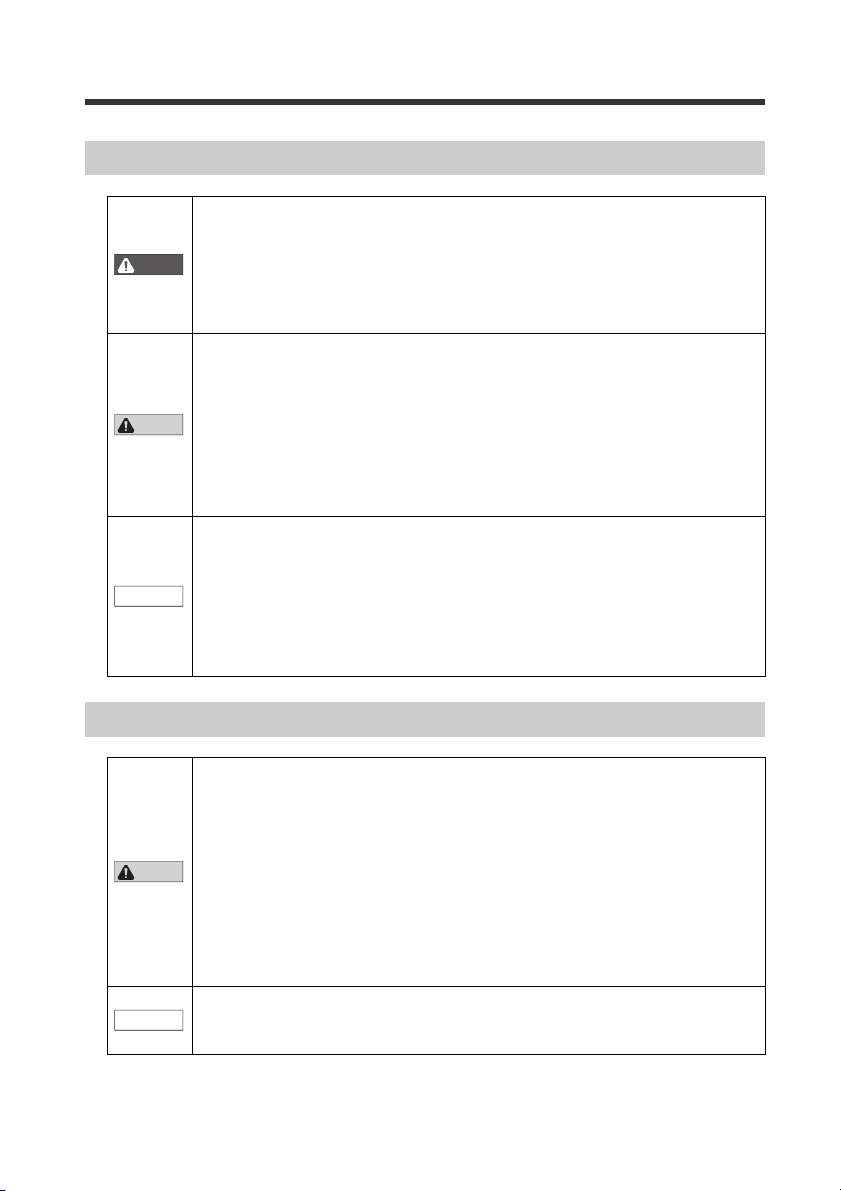
Relevant Manuals
Manuals relevant to
PROFIBUS DP master
PROFIBUS DP master
This manual
DL-PD1
(This unit)
Manuals of sensor amplifier unit
Sensor Amplifier
The manuals to relevant to this document are as follows:
Example: GT2 series user's manual
- PROFIBUS DP Compatible Network Unit DL-PD1 User's Manual (GT2) -
3
Page 6

Terms Used in This Document
This document uses the following terms:
Sensor amplifier A sensor amplifier connected to the DL-PD1.
Main unit A sensor amplifier that has a power line and can operate alone.
Expansion unit A sensor amplifier that does not have a power line and must be connected to a main unit.
D-bus The name of KEYENCE's wiring-saving system for sensor amplifiers.
Term Explanation
Supports GT2 Se ries high-accuracy digital contact sensors and others.
4
- PROFIBUS DP Compatible Network Unit DL-PD1 User's Manual (GT2) -
Page 7

Table of Co ntents
Introduction ......................................................................................................... 1
Safety Precautions.............................................................................................. 1
General Precautions............................................................................... 1
Precautions for Use ................................................................................ 1
Precautions for Installation ..................................................................... 2
Precautions for regulations and standards ............................................. 2
Relevant Manuals................................................................................................ 3
Terms Used in This Document .......................................................................... 4
Table of Contents................................................................................................ 5
Chapter 1 Before Using
1-1 Characteristics of the DL-PD1............................................................... 1-2
Types and Number of Connectable Sensor Amplifiers........................ 1-3
1-2 Checking the Package Contents........................................................... 1-4
Package Contents ............................................................................... 1-4
1-3 Names of Each Part................................................................................ 1-5
Chapter 2 Connection and Configuration
2-1 Installation and Connection to a Sensor Amplifier ............................. 2-2
Installation and Connection to Sensor Amplifiers ................................ 2-2
Setting the Station Address ................................................................. 2-6
2-2 Wiring ...................................................................................................... 2-7
Connecting the PROFIBUS ................................................................. 2-7
2-3 Technical data......................................................................................... 2-8
Dimensions.......................................................................................... 2-8
General Specifications......................................................................... 2-9
Chapter 3 Executing Communication
3-1 PROFIBUS communication function of DL-PD1.................................. 3-2
Overview.............................................................................................. 3-2
PROFIBUS Specifications ................................................................... 3-3
Operational flow for test operation....................................................... 3-4
Slot number and ID number assignment............................................. 3-5
3-2 Hardware configuration ......................................................................... 3-6
Operation mode of DL-PD1 ................................................................. 3-6
Input/Output size.................................................................................. 3-7
3-3 Parameterization..................................................................................... 3-8
3-4 Diagnostic Function ............................................................................. 3-10
Slave diagnosis structure................................................................... 3-10
- PROFIBUS DP Compatible Network Unit DL-PD1 User's Manual (GT2) -
5
Page 8

Station status ..................................................................................... 3-11
PROFIBUS DP master address ......................................................... 3-12
Manufacturer ID ................................................................................. 3-12
Identifier-related diagnosis................................................................. 3-13
Module status..................................................................................... 3-13
Channel-related diagnosis ................................................................. 3-15
3-5 Overview of PROFIBUS DP Communication ...................................... 3-17
Cyclic communication ........................................................................ 3-17
Device maps ...................................................................................... 3-18
Communication Methods ...................................................................3-23
3-6 DP-V1 Service........................................................................................ 3-26
DL-PD1 index (Slot 0) ........................................................................3-26
GT2 series index (Slot 1 to 15) ..........................................................3-30
3-7 Other functions ..................................................................................... 3-36
I&M..................................................................................................... 3-36
FREEZE/SYNC/CLEAR command .................................................... 3-37
Chapter 4 Appendix
4-1 Troubleshooting...................................................................................... 4-2
Indicator Specifications ........................................................................ 4-2
Types of error and error code .............................................................. 4-3
4-2 Data update time.....................................................................................4-5
4-3 Comparator Value Property of the Sensor Amplifier...........................4-6
6
- PROFIBUS DP Compatible Network Unit DL-PD1 User's Manual (GT2) -
Page 9

Before Using
This chapter provides an overview of the DL-PD1 and describes its
part names and functions.
1-1 Characteristics of the DL-PD1 ............................ 1-2
1-2 Checking the Package Contents ........................1-4
1-3 Names of Each Part ........................................... 1-5
1
- PROFIBUS DP Compatible Network Unit DL-PD1 User's Manual (GT2) -
1-1
Page 10
1
1-1 Characteristics of the DL-PD1
PROFIBUS DP master
D-bus compatible sensor amplifier I/O etc.
DL-PD1
The DL-PD1 is an interface unit, which enables sensor amplifiers or input units to
connect to the PROFIBUS DP. The characteristics of the DL-PD1 are shown below.
Slave unit of the PROFIBUS DP-V1
Before Using
The following features are achieved by connecting the sensor amplifiers, which
are suitable for each application, in the form of a module.
• Reading out the output of the sensor amplifier.
• Reading out the comparator value (the measurement value) of the sensor
amplifier.
• Changing the configuration of the sensor amplifier.
Two selectable operational modes
• Monitor Mode: Input size - MAX 107 bytes, Output size - MAX 16 bytes
• I/O Mode: Input size - 10 bytes, Output size - 10 bytes
Corresponding to the communication speed of 9.6 Kbits/s to 12 Mbits/s
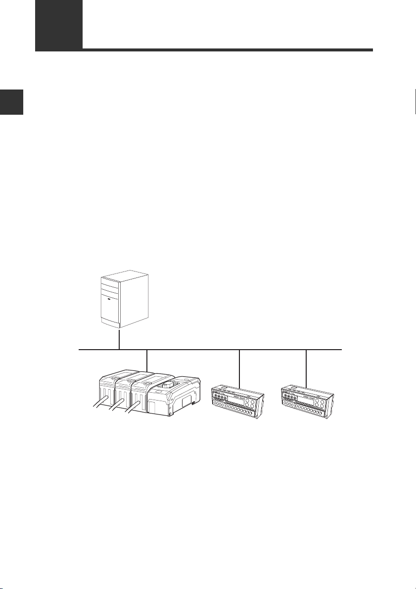
System configuration example
Additional sensor amplifiers corresponding to the D-bus can be connected to the DLPD1. ("D-bus" is the name of KEYENCE's wiring-saving system for sensor amplifiers.)
Any sensor amplifiers corresponding to the D-bus allow different models and up to 15
units of sensor amplifiers to be connected simultaneously.
Connectable quantity depends on the sensor amplifier which is connected to.
1-2
- PROFIBUS DP Compatible Network Unit DL-PD1 User's Manual (GT2) -
Page 11

1-1 Characteristics of the DL-PD1
1
Types and Number of Connectable Sensor Amplifiers
Number of Connectable Sensor Amplifiers
Name Amplifier form Main unit Expansion unit Maximum number of connectable units
DIN rail mounting
type
GT-2 Series
Panel mounting type
Large display type
* Up to 11 sensor heads can be connected by adding a head connection board to the
main unit.
The DL-PD1 can connect to multiple sensor amplifiers (a single main unit and multiple
expansion units) which support D-bus. "D-bus" is the name of KEYENCE's wiring-saving
system for sensor amplifiers.
Different types of sensor amplifiers with D-bus support can be connected to a single DLPD1 unit.
How many and what types of sensor amplifiers can be connected depends on the
sensor amplifiers or units to be connected. Please inquire for details.
GT2-71(M)(C)N
GT2-71(M)(C)P
GT2-75N
GT2-75P
GT2-100N
GT2-100P
GT2-71(M)(C)N
GT2-71(M)(C)P15(1 main unit, 14 expansion units)
GT2-76N
GT2-76P
-
15
(1 main unit, 14 expansion units)
1
(1 main unit)*
Before Using
- PROFIBUS DP Compatible Network Unit DL-PD1 User's Manual (GT2) -
1-3
Page 12
1
1-2 Checking the Package Contents
Before using the DL-PD1, make sure that the following equipment and accessories are
included in the package.
We have thoroughly inspected the package contents before shipment. However, in the
event of defective or broken items, contact your nearest KEYENCE office.
Before Using
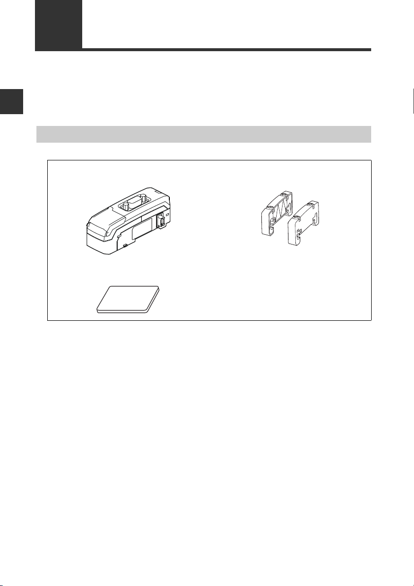
Package Contents
DL-PD1 main unit x 1 End units (OP-26751: a two-unit set) x 1
Expansion connector sticker x 1 Ferrite core x 1
Instruction manual x 1
1-4
- PROFIBUS DP Compatible Network Unit DL-PD1 User's Manual (GT2) -
Page 13
1
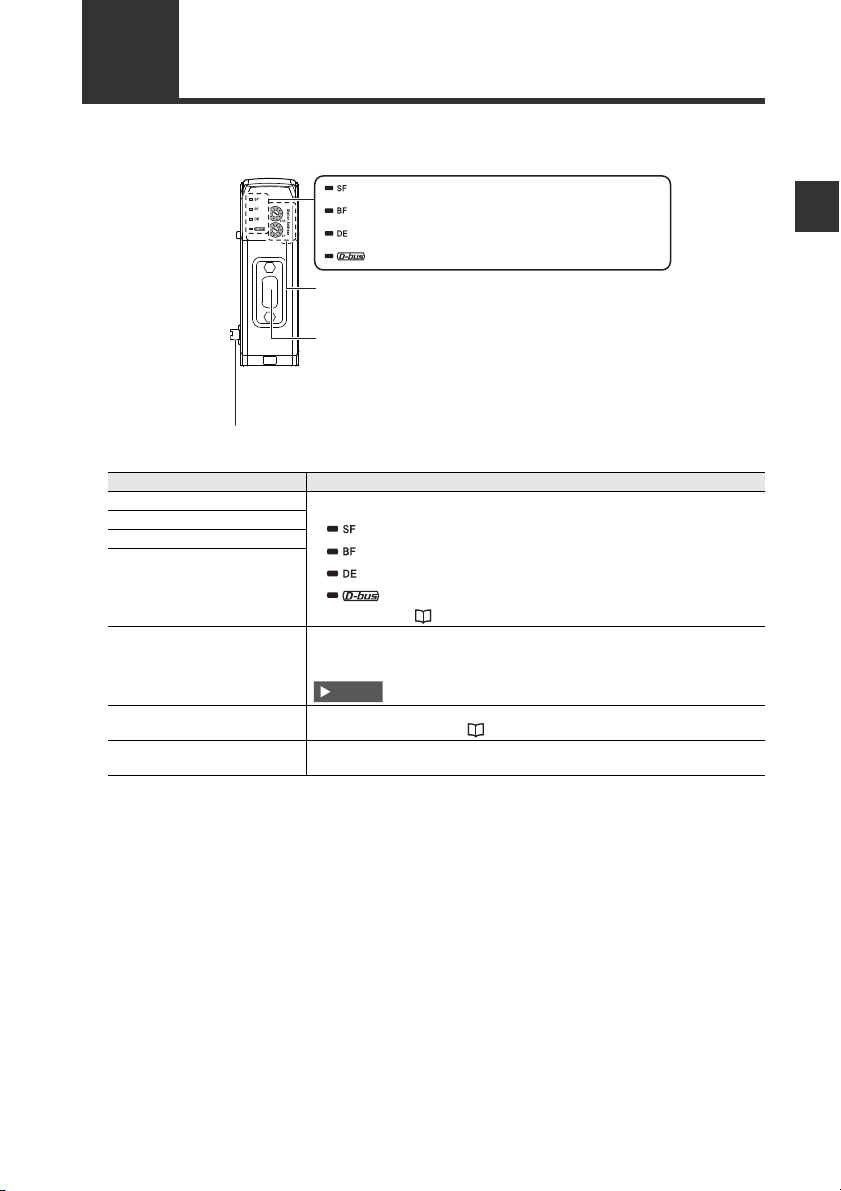
1-3 Names of Each Part
(1) Station Failure Indicator
(2) Bus Failure Indicator
(3) Data Exchange Indicator
(4) Sensor amplifier communication indicator
(5) Station address setting switch
(6) PROFIBUS connector
(7) Sensor amplifier connector
OFF
OFF
Lit in green
Lit in green
Important
This section describes the part names and functions of the DL-PD1.
Before Using
(1) Station Failure Indicator Normal lighting is as below.
(2) Bus Failure Indicator
(3) Data Exchange Indicator
(4) Sensor amplifier
communication indicator
(5) Station address setting switch
(6) PROFIBUS connector
(7) Sensor amplifier connector
Item Description
For details, refer to "Indicator Specifications" (page 4-2).
Set the station address.
The place of x10: 10, the place of x1: 1
[Setting range]: 01 to 99, [Default value]: 11
The station address of the DL-PD1 cannot be set to 00, 100, or more.
D-sub9 pin (socket) connector compliant with the RS-485.
For details on pin layout, see "Connecting the PROFIBUS" (page 2-7).
Attach the sensor amplifier to this connector.
When shipped from the factory, a protection cover is installed.
- PROFIBUS DP Compatible Network Unit DL-PD1 User's Manual (GT2) -
1-5
Page 14

1-3 Names of Each Part
1
Before Using
MEMO
1-6
- PROFIBUS DP Compatible Network Unit DL-PD1 User's Manual (GT2) -
Page 15

Connection and Configuration
This chapter describes installation and wiring for the DL-PD1.
2-1 Installation and Connection to a Sensor Amplifier..2-2
2-2 Wiring ................................................................. 2-7
2-3 Technical data .................................................... 2-8
2
- PROFIBUS DP Compatible Network Unit DL-PD1 User's Manual (GT2) -
2-1
Page 16
2
2-1
Point
Reference
(1)
(3)
(2)
DL-PD1
Sensor amplifier
Expansion connector
This section provides the procedures for installing the DL-PD1 and connecting to sensor
amplifiers.
The DL-PD1 can be connected with the sensor amplifiers which support D-bus. ("D-bus"
is the name of KEYENCE's wiring-saving system for sensor amplifiers.) How many
sensor amplifiers can be connected depends on the sensor amplifiers to be connected.
For specific numbers of connections, refer to the manual of each sensor amplifier.
Installation and Connection to a Sensor Amplifier
Connection and Configuration
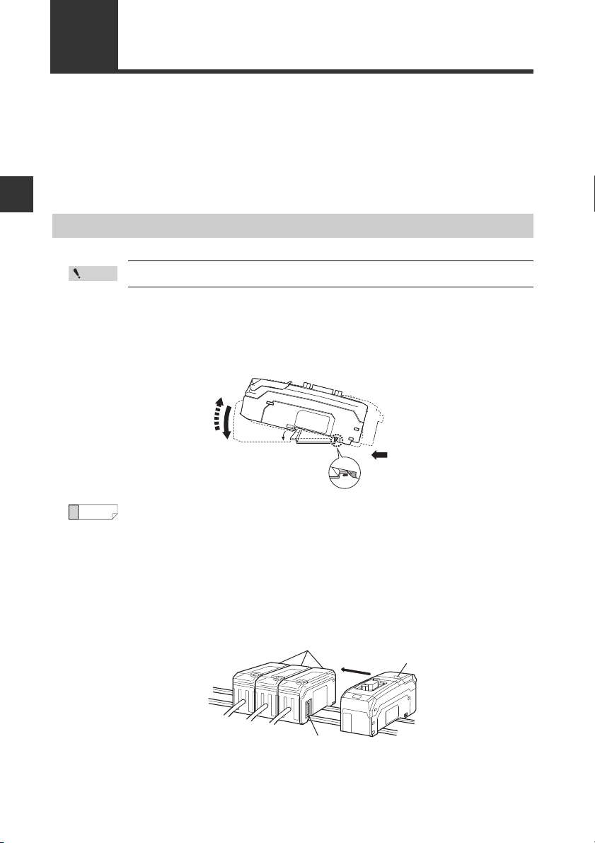
Installation and Connection to Sensor Amplifiers
Turn off the power before connecting the DL-PD1 and sensor amplifier.
1 Align the claw on the bottom of the DL-PD1 with the DIN rail. While pushing
the amplifier in the direction of arrow (1), press down in the direction of arrow
(2).
To remove the DL-PD1, raise the amplifier in the direction of arrow (3) while
pushing the amplifier in the direction of arrow (1).
2 Repeat step 1 to install additional sensor amplifiers or input units on the DIN
rail and connect them to the DL-PD1.
If the sensor amplifier connector has an expansion protective cover, remove the
cover before connecting the amplifier.
2-2
- PROFIBUS DP Compatible Network Unit DL-PD1 User's Manual (GT2) -
Page 17

2-1 Installation and Connection to a Sensor Amplifier
2
NOTICE
End unit
End unit
NOTICE
Make sure that the sensor amplifier connector (for DIN rail mounting
type) is not askew on the side face of the DL-PD1, as shown below. If
the connector is askew, the DL-PD1 may become damaged when
connected to the sensor amplifier.
Sensor amplifier connector
DL-PD1
3 Mount the end units (OP-26751: a two-unit set shipped with the DL-PD1) on
both sides of the DL-PD1 and the sensor amplifier. Then, fix the end units
with the screws on the top of each end unit. (Tightening torque: 0.6 N•m or
less)
Mount the end units in the same way as the DL-PD1.
Connection and Configuration
Press the DL-PD1 into full engagement with the sensor amplifier. If
the DL-PD1 is not correctly connected, it may be damaged when the
power is turned on.
- PROFIBUS DP Compatible Network Unit DL-PD1 User's Manual (GT2) -
2-3
Page 18
2-1 Installation and Connection to a Sensor Amplifier
2
Expansion cable (300 mm long)
Peel off the protective sticker.
NOTICE
Sensor amplifier connector
(for DIN rail mounting type)
Expansion
connector sticker
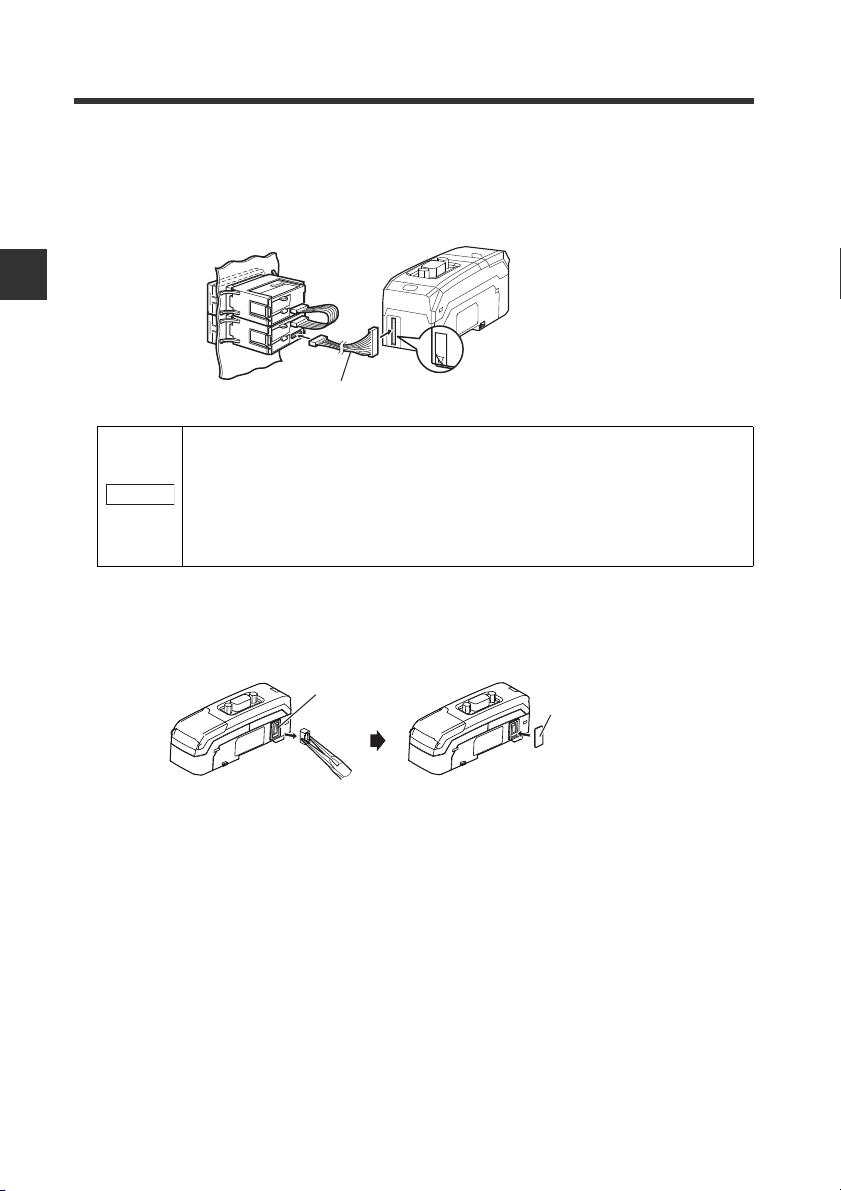
Connecting to sensor amplifiers (panel mounting type)
1 Connect the optional expansion cable (OP-35361) between the sensor
amplifier and the DL-PD1.
Connection and Configuration
• Turn off the power and connect the expansion cable securely. If the
cable is not correctly connected, the DL-PD1 may be damaged
when the power is turned on.
• Do not attach or detach the cable with the power on, as this may
damage the DL-PD1.
2 Remove the sensor amplifier connector (for DIN rail mounting type) from the
DL-PD1, using pliers. In its place, attach the expansion connector sticker
supplied with the DL-PD1.
2-4
- PROFIBUS DP Compatible Network Unit DL-PD1 User's Manual (GT2) -
Page 19
2-1 Installation and Connection to a Sensor Amplifier
2
Detach the
protection sticker.
Detach the
protection
sticker.
Expansion cable (cable length:300 mm)
NOTICE
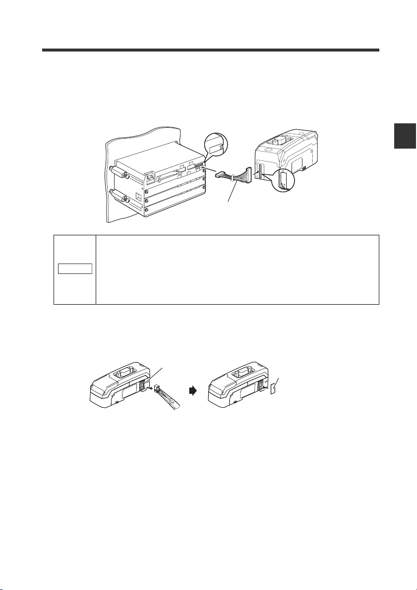
Connecting to a large display type sensor amplifier
1 Connect the optional expansion cable (OP-35361) between the sensor
amplifier and the DL-PD1.
• Turn off the power and connect the expansion cable securely. If the
cable is not correctly connected, the DL-PD1 may be damaged
when the power is turned on.
• Do not attach or detach the cable with the power on, as this may
damage the DL-PD1.
2 Remove the sensor amplifier connector (for DIN rail mounting type) from the
DL-PD1, using pliers. In its place, attach the expansion connector sticker
supplied with the DL-PD1.
Sensor amplifier connector
(for DIN rail mounting type)
Expansion
connector sticker
Connection and Configuration
- PROFIBUS DP Compatible Network Unit DL-PD1 User's Manual (GT2) -
2-5
Page 20

2-1 Installation and Connection to a Sensor Amplifier
2
Point
Station address setting switch Setting range: 01 to 99
Default value: 11
Setting the Station Address
Set the station address of the DL-PD1 with the rotary switch at the top of the DL-PD1.
The station address set here must be the same as the one set through the configuration
software of the PROFIBUS DP.
Connection and Configuration
• The station address of the DL-PD1 cannot be set to 00, 100, or more.
• Set the station address before the DL-PD1 is powered on. When the
station address is changed during operations of the DL-PD1, such
change is reflected after power has been restored to the DL-PD1.
• The station address setting (Set_Slave_Adress) via PROFIBUS DP is
not supported.
2-6
- PROFIBUS DP Compatible Network Unit DL-PD1 User's Manual (GT2) -
Page 21
2
2-2 Wiring
Point
5
1
2
3
4
9
8
7
6
This section describes wiring for the DL-PD1.
Also refer to the Recommendation for Cabling and Assembly published by PROFIBUS
International.
Turn off the power before wiring.
Connecting the PROFIBUS
Use the following procedure to connect the DL-PD1 to the PROFIBUS.
Usable cable
Use the shielded twisted pair cable, which is compliant with the PROFIBUS
specifications.
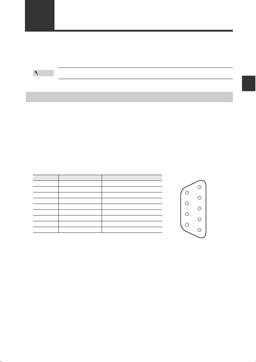
Wiring the PROFIBUS Connector
For the PROFIBUS connector of the DL-PD1, the D-sub 9 pin connector (socket) is
used. Pin arrangement of the connector is as below.
Pin number Signal name Description
1- -
2- -
3 RxD/TxD-P Data line B
4 RTS Request to send
5 M5V2 Data reference potential (Station)
6 P5V2 Power supply: Plus (Station)
7- -
8 RxD/TxD-N Data line A
9- -
Connection and Configuration
- PROFIBUS DP Compatible Network Unit DL-PD1 User's Manual (GT2) -
2-7
Page 22

Connection and Configuration
2
38.1
When cover is opened :
54.7 max.
105° max.
57.4
(0.2)
35.443.5
94.5
(39.0)
34.6 1.8
29.4
Unit : mm
6
9.235.4
53.8
20.8
26.4
2-3 Technical data
Dimensions
DL-PD1
End Unit
2-8
- PROFIBUS DP Compatible Network Unit DL-PD1 User's Manual (GT2) -
Page 23

2
General Specifications
2-3 Technical data
Model DL-PD1
PROFIBUS DP
specifications
Sensor amplifier
connection
specifications
Power vol ta ge
Power consumption 1600 mW or less (65 mA max. at 24 V)
Environmental
resistance
Materials
Weight (including connectors) Approx. 65 g
Device type DP-V1 Slave (D-sub 9 pin, Number of the por ts: 1)
Communication speed 9.6 kbit/s to 12 Mbit/s
Cable length
Connectable Sensor
amplifiers
Number of connectable
Sensor amplifier units
Operating surrounding
air temperature
Operating surrounding
air humidity
Vibration resistance IEC60068-2-6 2G (10 to 500 Hz, 2 hours each in X, Y, Z direction)
Impact resistance IEC60068-2-27 30G (11 ms, 3 times e ach in X, Y, Z direction)
9.6 / 19.2 / 45.45 / 93.75 kbit/s: 1200 m
187.5 kbit/s: 1000 m
500 kbit/s: 400 m
1.5 Mbit/s: 200 m
3 / 6 / 12 Mbit/s: 100 m
Sensor amplifiers with D-bus suppor t
15 units max.
20 to 30 VDC, including ripple (p-p) 10%
(This voltage is supplied from the connected sensor amplifier.)
-20 to +55°C (no freezing)
35 to 85% RH (no condensation)
Main unit case and dust cover: Polycarbonate
PROFIBUS connector: Steel - Nickel plating
*2
*1
*1 "D-bus" is the name of KEYENCE's wiring-saving system for sensor amplifiers.
*2 Varies with the sensor amplifiers connected.
Connection and Configuration
- PROFIBUS DP Compatible Network Unit DL-PD1 User's Manual (GT2) -
2-9
Page 24

2-3 Technical data
2
Connection and Configuration
MEMO
2-10
- PROFIBUS DP Compatible Network Unit DL-PD1 User's Manual (GT2) -
Page 25

Executing Communication
This chapter describes the functions and detailed communication
methods of PROFIBUS DP communication the DL-PD1 supports.
3-1
PROFIBUS communication function of DL-PD1
3-2 Hardware configuration ...................................... 3-6
3-3 Parameterization ................................................ 3-8
3-4 Diagnostic Function.......................................... 3-10
3-5 Overview of PROFIBUS DP Communication ...3-17
3-6 DP-V1 Service.................................................. 3-26
3-7 Other functions ................................................. 3-36
.... 3-2
3
- PROFIBUS DP Compatible Network Unit DL-PD1 User's Manual (GT2) -
3-1
Page 26

Executing Communication
3
IN area
OUT area
Output
Judgment value
Error information
External Input
PROFIBUS DP
master
DL-PD1
Sensor amplifier
Output
Judgment value
・・・・・・
・・・・・・
Error information
Setting value
Exteral input
Output
Judgment value
・・・・・・
・・・・・・
Error information
Setting value
External Input
Cyclic
communication
Cyclic
communication
DP-V1 service
Output
Judgment value
・・・・・・
・・・・・・
Error information
Setting value
Exteral input
IN area
OUT area
Read/write parameters
・・・・・・
・・・・・・
・・・・・・
3-1
PROFIBUS communication function of DL-PD1
This section describes the overview of the PROFIBUS DP communication functions the
DL-PD1 supports.
Overview
The DL-PD1 operates as a slave unit for PROFIBUS DP. The sensor amplifier output or
comparator value can be read via the cyclic communication, and the sensor amplifier's
external input ON/OFF can be controlled. Also, setting the DL-PD1 or sensor amplifier
connected to DL-PD1 and reading/writing the status of them are possible via the acyclic
communication of the DP-V1 service.
"Overview of PROFIBUS DP Communication" (page 3-17)
"DP-V1 Service" (page 3-26)
3-2
- PROFIBUS DP Compatible Network Unit DL-PD1 User's Manual (GT2) -
Page 27

3
PROFIBUS Specifications
3-1 PROFIBUS communication function of DL-PD1
GSD Revision 5
FMS No
Data transmission rate
Bus protocol PROFIBUS DP
Interface RS-485
Modular Device Yes (Monitor mode only)
module max.15 units
Address
space
PROFIBUS DEVICE ID 0DFD
Redundancy No
P24V signal No
FREEZE capability Yes
SYNC capability Yes
Auto Baudrate Yes
Set_Slave_Adress No
Min_Slave_Interval 600 s
Fail-safe Mode Yes
DP-V1 Ye s
Alarm No
I&M data Compatible with I&M0
Clocking No
Firmware update No
Address 1 to 99
Item Specifications
9.6 / 19.2 / 45.45 / 93.75 / 187.5 / 500 kbit/s
1.5 / 3 / 6 / 12 Mbit/s
I/O Mode inputs: 10 bytes, outputs: 10 bytes
Monitor Mode inputs: max.107 bytes, outputs: max.16 bytes
H
Executing Communication
- PROFIBUS DP Compatible Network Unit DL-PD1 User's Manual (GT2) -
3-3
Page 28

3-1 PROFIBUS communication function of DL-PD1
3
Operational flow for test operation
The following settings using the PROFIBUS DP configuration software are required for
the DL-PD1 to connect and communicate with the PROFIBUS DP master.
1 Read the GSD file.
The DL-PD1 functions for PROFIBUS DP are defined by the GSD file.
The GSD file can be downloaded from KEYENCE homepage. Read the
downloaded GSD file using the configuration software and install it.
Executing Communication
http://www.keyence.com
2 Add the DL-PD1 to the PROFIBUS DP system.
Reading the GSD file using the configuration software can add the DL-PD1 and
sensor amplifier to the hardware catalog of the configuration software Select the
DL-PD1 from the hardware catalog and add to the PROFIBUS DP system.
"Hardware configuration" (page 3-6)
3 Add the sensor amplifier.
Select the sensor amplifier to connect to the DL-PD1 from the hardware catalog
and add to the PROFIBUS DP system.
"Hardware configuration" (page 3-6)
"Slot number and ID number assignment" (page 3-5)
4 Set the DL-PD1 parameter as necessary.
The parameter setting is not necessary when reading only sensor amplifier output
via cyclic communication.
"Parameterization" (page 3-8)
3-4
- PROFIBUS DP Compatible Network Unit DL-PD1 User's Manual (GT2) -
Page 29

3-1 PROFIBUS communication function of DL-PD1
3
Point
02
...
1501
02
...
1501
Main
unit
Expansion unit
Sensor amplifier
DL-PD1
00
00
ID number
Slot number
Slot number and ID number assignment
When the sensor amplifiers are connected to the DL-PD1, slot numbers are assigned to
each sensor amplifier. When using the acyclic communication with the DP-V1 service or
diagnostic function used, the slot number is used to specify the target sensor amplifier
for communication.
Also, ID numbers are assigned to the control output and external input of each sensor
amplifier in the connection order of sensor amplifiers. ID numbers are used to identify
the control output of the sensor amplifier assigned as cyclic communication data.
(Configuration example)
Executing Communication
Slot numbers and ID numbers are automatically assigned in the
connection order for sensor amplifiers. If the number of connected
sensor amplifiers or connection order is changed, the control program
may have to be changed. Design the sensor amplifier configuration
and control program with this taken into account beforehand.
"Operation mode of DL-PD1" (page 3-6)
If the effective ID setting is changed on the GT2-100N (P), restart the
GT2-100N (P). After restarting the GT2-100N (P), the DL-PD1
recognizes the specified number of units and communication with the
units is possible.
- PROFIBUS DP Compatible Network Unit DL-PD1 User's Manual (GT2) -
3-5
Page 30

3
3-2
Set the hardware configuration on the configuration software of PROFIBUS DP
according to the physical configuration of the DL-PD1 and sensor amplifier connected to
the DL-PD1. The setting procedure differs depending on the operation mode of DL-PD1.
Operation mode of DL-PD1
There are two types of operation modes for DL-PD1. The operation modes for DL-PD1
are switched on the hardware configuration using the configuration software of
PROFIBUS DP.
Monitor mode
Executing Communication
Use this mode to obtain the comparator value and status of sensor amplifiers via cyclic
communication. The input size and output size for cyclic communication change
depending on the number of sensor amplifiers connected. The maximum sizes for input
and output are 107 bytes and 16 bytes respectively.
When using the monitor mode, assign the "DL-PD1" and each sensor amplifier to the
PROFIBUS DP system on the hardware configuration.
When using the master compatible with the DP-V1, any of the modes can be used to
read or write all information on the sensor amplifier via acyclic communication of DP-V1
service.
DL-PD1 Monitor mode
DL-PD1 (without Sensor
amplifier)
Hardware configuration
Unit assigned on the
configuration
"DP-V1 Service" (page 3-26)
Operation mode
of DL-PD1
I/O mode
Cyclic communication
Control
Comparator
Error
output
value
External
information
input
* When using Class 2 master only
Cannot be used with Class 1 master.
Acyclic
communication
(DP-V1 service)
*
I/O mode
Use this mode to reduce the input/output size of cyclic communication to minimum. The
input size and output size are 10 bytes each regardless of the number of sensor
amplifiers connected. Using the cyclic communication, the control output of sensor
amplifiers can be read and external output to sensor amplifiers can be performed.
When using the I/O mode, assign the "DL-PD1 without sensor amplifier" to the
PROFIBUS DP system on the hardware configuration. Do not assign the sensor
amplifier.
3-6
- PROFIBUS DP Compatible Network Unit DL-PD1 User's Manual (GT2) -
Page 31

3-2 Hardware configuration
3
Input/Output size
When DL-PD1 is in the monitor mode
The input/output size changes according to the number of sensor amplifiers connected.
Assign the "DL-PD1" and each sensor amplifier to the PROFIBUS DP system on the
hardware configuration using the configuration software of PROFIBUS DP.
Slot
* How many sensor amplifiers can be connected depends on the sensor amplifiers to
When DL-PD1 is in the I/O mode
The input/output size is fixed regardless of the number of sensor amplifiers connected.
Assign the "DL-PD1 without sensor amplifier" to the PROFIBUS DP system on the
hardware configuration using the configuration software of PROFIBUS DP.
Slot
Cyclic communication
:
input output
7 bytes 1 byte
0 2 bytes 1 byte
1
15*
be connected. For specific numbers of connections, refer to the manual of each
sensor amplifier.
Cyclic communication
0 10bytes 10bytes
input output
Executing Communication
- PROFIBUS DP Compatible Network Unit DL-PD1 User's Manual (GT2) -
3-7
Page 32

3
3-3 Parameterization
Set parameters on the configuration software of PROFIBUS DP.
Set as necessary.
Standard parameter
Parameters specified by PROFIBUS DP/DPV1 standard
Octet Name Description Valu e
1 Station Status Station status
Executing Communication
2 WD_Fact_1 Watchdog element 1 -
3 WD_Fact_2 Watchdog element 2 -
4 TSDR Shortest TSDR time -
5 Ident number (H) Manufacturer code (high byte) 0D
6 Ident number (L) Manufacturer code (low byte) FD
7 Group ID
8 DPV1 Status1 DPV1 status 1 (See EN50170.)
9 DPV1 Status2 DPV1 status 2 (See EN50170.)
10 DPV1 Status3 DPV1 status 3 (See EN50170.) 0 (fixed)
Group assignment for broadcast and
multi cast (SYNC,FREEZE, CLEAR)
BIT2-0: reserved
BIT3: Watchdog on
BIT4: Freeze mode request
BIT5: Sync mode request
BIT6: Unlock request
BIT7: Lock request
H
H
-
BIT1-0: reserved
BIT2: Watchdog time base 1 ms
BIT4-3: reserved
BIT5: 0 (fixed)
BIT6: Fail_safe
BIT7: DP-V1_Enable
(Default value: 1100 0000B)
BIT0: Check_Cfg_Mode
BIT1: reserved
BIT7-2: 0 (fixed)
(Default value: 0000 0001B)
3-8
- PROFIBUS DP Compatible Network Unit DL-PD1 User's Manual (GT2) -
Page 33

3
Vender parameter
bit 7
:
:
0
Slot 15 Slot 8
bit 7
:
:
0
Slot 7 Slot 0
bit 7
:
:
0
Slot 15 Slot 8
bit 7
:
:
0
Slot 7 Slot 0
Unique parameters for DL-PD1
Octet Name Description Valu e
11 Reserved - 1 (fixed)
12 Data Format
13 Extended Diagnosis
Selects data storage format when
sending/receiving 2 bytes or larger data.
Selects whether to include information
other than standard diagnosis into slave
diagnosis.
0: Intel (little endian)
1: Motorola (big endian)
0: Disable
1: Enable
3-3 Parameterization
: Default value
14
Indicate error slot
[Sensor Amplifier]
15
16
Indicate warning slot
[Sensor Amplifier]
17
18 Reserved - 0 (fixed)
Selects the sensor amplifier as a target
for slave diagnosis. If the sensor
amplifier is set as a target, set bit
corresponding to the slot number.
"Diagnostic Function" (page 3-10)
Selects whether to include warning
information into slave diagnosis
information. If so, set bit corresponding
to the slot number.
(Default value: 1111 1111B)
(Default value: 1111 1110B)
Slot 0 is fixed to 0.
(Default value: 0)
(Default value: 0)
Executing Communication
- PROFIBUS DP Compatible Network Unit DL-PD1 User's Manual (GT2) -
3-9
Page 34

Executing Communication
3
1
2
3
4
5
6
7
:
10
11
:
19
20
:
67
:
:
:
Octet
Station status 1 to 3
PROFIBUS DP master address
Manufacturer ID
Identifier-related diagnosis
(Error information)
Module status
Channel-related diagnosis
Minimum 3 bytes
3 bytes increase per slot
Standard Diagnosis
Channel-related
Diagnosis
3-4 Diagnostic Function
Using the slave diagnostic function of PROFIBUS DP, the information of error caused on
the DL-PD1 or sensor amplifier can be sent to the master via PROFIBUS DP.
Slave diagnosis structure
The frame length of the DL-PD1 slave diagnosis is the maximum of 67 bytes. The slave
diagnosis consists of 6-byte standard diagnosis, 4-byte Identifier-related diagnosis, 9byte module status and maximum of 48-byte Channel-related diagnosis. The frame
length of the Channel-related diagnosis changes depending on the number of sensor
amplifiers connected. The minimum length is 3 bytes and the length increases 3 bytes
per sensor amplifier additionally connected.
Also, the diagnostic function can be set to Enable/Disable by slot at the parameter
setting for DL-PD1. When the diagnostic function is set to Disable, the slot information is
deleted from the diagnostic frame.
"Parameterization" (page 3-8)
3-10
- PROFIBUS DP Compatible Network Unit DL-PD1 User's Manual (GT2) -
Page 35

3-4 Diagnostic Function
3
Station status
Information indicating the overview of the DL-PD1 status is stored in Octet 1 to 3. If an
error occurs, each bit for Octet 1 to 3 is set. Refer to the following contents and eliminate
the cause of error.
Station status 1
Octet bit Content Solution
0 Cannot be accessed from the DP master to the DP slave.
1 The DP slave is not ready to exchange data yet. Wait. The DP slave is now starting up.
The configuration data transferred from the DP master to
2
the DP slave does not match with the slave configuration.
31 (fixed) -
40 (fixed) -
1
The DP master cannot decode the response of the DP
5
slave.
The type of DP slave does not match to the software
6
configuration.
Parameters are assigned to the DP slave by the different
7
DP master (not the DP master currently having the
access right to the DP slave).
• Is the correct PROFIBUS address set
to the DP slave?
• Is the bus connector connected?
• Is the RS485 repeater properly set?
• Is the DP slave set?
Check if the slave setting on the
configuration software is correctly made.
Check the configuration of the bus.
Check if the station type set on the
configuration software is correct.
• For example, when accessing to the
DP slave using the programming
device or another DP master, this bit is
always 1.
• The PROFIBUS address of DP master
which assigned parameters to the DP
slave is in the diagnosis byte.
Executing Communication
- PROFIBUS DP Compatible Network Unit DL-PD1 User's Manual (GT2) -
3-11
Page 36

3-4 Diagnostic Function
3
Station status 2
Octet bit Content
Executing Communication
*1 This bit is updated only when another diagnosis message is updated, too.
Station status 3
Octet bit Content
PROFIBUS DP master address
The PROFIBUS address of PROFIBUS DP master is stored in Octet 4. When the value
is FF
Manufacturer ID
Codes unique for the DL-PD1 status are stored in Octet 5 and 6.
Octet Content Valu e
0 Set the DL-PD1 parameter again.
A diagnosis message is present. The DP slave does not operate until the problem is eliminated.
1
(Static diagnosis message)
2 (1 fixed)
3 The watchdog is enabled.
2
4 The DP slave is in "FREEZE" state.
5 The DP slave is in "SYNC" state.
6 (0 fixed)
7 The DP slave is disabled.
0
:6(0 fixed)
3
7 Diagnosis messages exceed the maximum amount that can be stored. Increase the storing memory.
, the parameter is not assigned.
H
5 Manufacturer ID is stored. (high byte) 0D
6 Manufacturer ID is stored. (low byte) FD
*1
*1
H
H
3-12
- PROFIBUS DP Compatible Network Unit DL-PD1 User's Manual (GT2) -
Page 37

3-4 Diagnostic Function
3
Identifier-related diagnosis
Information to identify the unit where an error occurred is stored in Octet 7 to 10.
Octet Content bit Valu e
Length of the Identifier-related diagnosis
7
Code for Identifier-related diagnosis
BIT corresponding to the module where an error has occurred
8
is set.
(Slot 0 to 7)
BIT corresponding to the module where an error has occurred
9
is set.
(Slot 8 to 15)
10 Reserved
0
00 0100B (fixed) :
5
6
01B (fixed)
7
0 Error in Slot 0 (DL-PD1)
::
7 Error in Slot 7 (Sensor amplifier)
0 Error in Slot 8 (Sensor amplifier)
::
7 Error in Slot 15 (Sensor amplifier)
0
:70000
B
Module status
Error information is stored in Octet 11 to 19 when the hardware configuration on the
configuration software does not coincide with the actual configuration.
Octet Content bit Valu e
Length of the Module status
11
Code for Module status
12 Status Type module Status
13 Reserved
14 Reserved
0
5
6
7
0
7
0
7
0
7
00 1001B (fixed):
00B (fixed)
130D (fixed):
0 (fixed):
0 (fixed):
Executing Communication
- PROFIBUS DP Compatible Network Unit DL-PD1 User's Manual (GT2) -
3-13
Page 38

3-4 Diagnostic Function
3
DL-PD1
DL-PD1
GT2-71N
GT2-72N
GT2-72N
IL-1050
10234
GT2-71N
GT2-72N
IL-1050
1023
Configuration on the
configuration software
Module status in the state as shown on
the left
Byte Val ue
10 00 00 10 01
B
11 10 00 00 10
B
12 00 00 00 00
B
13 00 00 00 00
B
14
10 00 00 00
B
3210 Slot number
15
00 00 00 11
B
7654 Slot number
::
Slot number
Slot number
Actual configuration
Executing Communication
Octet Content bit Val ue
Slot 0 module status
Slot 1 module status
15
Slot 2 module status
Slot 3 module status
Slot 4 module status
16
Slot 7 module status
Slot 8 module status
17
Slot 11 module status
Slot 12 module status
18
Slot 15 module status
19 Reserved for system
::
::
::
0
1
2
3
4
5
6
7
00B:Normal
0
01B: System error
10B: The unit on the configuration
1
6
7
0
1
6
7
0
1
6
7
0
:70000B (fixed)
does not match the unit
actually connected.
11B: The unit is connected despite
the unit is not assigned on the
configuration, or the unit is not
connected despite the unit is
assigned on the configuration.
Example)
3-14
- PROFIBUS DP Compatible Network Unit DL-PD1 User's Manual (GT2) -
Page 39

3-4 Diagnostic Function
3
Channel-related diagnosis
Information indicating the error content in 3byte per module (sensor amplifier) is stored
in Octet 20 to 67. The frame length of the diagnosis changes depending on the number
of module (sensor amplifier) connected (3 + 3 x [number of module (sensor amplifier)
connected]).
Also, Information of the module (sensor amplifier) for which the diagnostic function is set
to Disable for the parameter settings is deleted from the frame and subsequent data is
offset.
"Parameterization" (page 3-8)
Octet Content bit Valu e
Identifier Number
20
Code for Channel-related diagnosis
Channel Number
21
Slot 0 (DL-PD1)
Slot 1 (Sensor amplifier)
Channel Type
Error Type of Slot 0
22
Channel Type
Identifier Number
23
Code for Channel-related diagnosis
Channel Number
24
Channel Type
Error Type of Slot 1
25
Channel type
::
0
00 0000B (fix):
5
6
10B (fix)
7
0
00 0000B (fix):
5
6
11B (fix) : Input and Output
7
0
:
(page 4-3)
4
5
000B (fix):
7
0
00 0001B (fix):
5
6
10B (fix)
7
0
00 0000B (fix):
5
6
11B (fix) : Input and Output
7
0
:
(page 4-3)
4
5
000B (fix):
7
Executing Communication
"Types of error and error code"
"Types of error and error code"
- PROFIBUS DP Compatible Network Unit DL-PD1 User's Manual (GT2) -
3-15
Page 40

3-4 Diagnostic Function
3
Executing Communication
Octet Content bit Valu e
Identifier Number
65
Code for Channel-related diagnosis
Channel Number
66
Channel Type
Slot 15 (Sensor amplifier)
Error Type of Slot 15
67
Channel Type
0
00 1111B (fix):
5
6
10B (fix)
7
0
00 0000B (fix):
5
6
11B (fix) : Input and Output
7
0
:
(page 4-3)
4
5
000B (fix):
7
"Types of error and error code"
3-16
- PROFIBUS DP Compatible Network Unit DL-PD1 User's Manual (GT2) -
Page 41

3
3-5
Overview of PROFIBUS DP Communication
The DL-PD1 enables you to read or write various settings and conditions of the sensor
amplifier via PROFIBUS DP.
Examples are shown below.
Item
Reading the sensor amplifier control output
Executing the external input to the sensor amplifier
Reading the sensor amplifier comparator value
Changing the sensor amplifier setting value
Cyclic communication
I/O
Mode
Monitor
Mode
DP-V1
Service
*
Reference
page
3-18
3-18
3-25
3-30
* When the DL-PD1 operation mode is the I/O mode
• When the master is Class 1, the DP-V1 service cannot be used.
• When the master is Class 2, the DP-V1 service can be used.
"Operation mode of DL-PD1" (page 3-6)
For the list of data that can be read or written over the cyclic communication, see
"Device maps" (page 3-18). For the list of data that can be read or written with the DPV1 service, see "DP-V1 Service" (page 3-26).
Cyclic communication
Executing Communication
Information and addresses assigned as the DL-PD1 cyclic communication data differ
depending on the DL-PD1 operation mode. When the DL-PD1 operation mode is the I/O
mode, the cyclic communication data assignment is fixed regardless of the connected
sensor amplifier. When the DL-PD1 operation mode is the monitor mode, assigned
information or addresses differ depending on the number and type of the connected
sensor amplifiers.
"Operation mode of DL-PD1" (page 3-6)
The storage format for 2byte data can be changed on the DL-PD1 parameter settings.
(In this example, data arrangement is shown in the big endian format.)
"Parameterization" (page 3-8)
- PROFIBUS DP Compatible Network Unit DL-PD1 User's Manual (GT2) -
3-17
Page 42

3-5 Overview of PROFIBUS DP Communication
3
Device maps
Monitor mode
In the monitor mode, the following functions can be performed.
• Reading the control output to the sensor amplifiers: "Parameterization" (page 3-8)
• External input request to the sensor amplifiers: "Parameterization" (page 3-8)
• Reading the comparator value: "Parameterization" (page 3-8)
• Reading the error status: "Parameterization" (page 3-8)
DL-PD1 (Slot 0)
Executing Communication
Input
Octet Bit Function name Description Valu e
0 Reserved for system - -
1 Reserved for system - -
2 Comparator value property Stores the comparator value status.
3 Reserved for system - -
4 Reserved for system - -
0
5 Sensor ready
6 Reserved for system - -
7 Error status
0 External input response 1
1 External input response 2
2 External input response 3
1
3 External input response 4
4 Reserved for system - -
5 Reserved for system - -
6 Reserved for system - -
7 Reserved for system - -
It is output when PROFIBUS DP
communication is established.
Stores the error status of the sensor
amplifiers.
"Types of error and error code"
(page 4-3)
Stores the external input response
to the sensor amplifier.
Stores the external input response
to the sensor amplifier.
Stores the external input response
to the sensor amplifier.
Stores the external input response
to the sensor amplifier.
0: Normal
1: Disabled status
“----”, “FFFF”, or “-FFFF”
0: Starting
1: Ready
0: No error occurred.
1: Error occurred.
0: No input
1: Input reception
0: No input
1: Input reception
0: No input
1: Input reception
0: No input
1: Input reception
3-18
- PROFIBUS DP Compatible Network Unit DL-PD1 User's Manual (GT2) -
Page 43

3
Output
3-5 Overview of PROFIBUS DP Communication
Octet Bit Function name Description Val ue
0 External input request 1
1 External input request 2
2 External input request 3
0
3 External input request 4
4 Reserved for system - -
5 Reserved for system - -
6 Reserved for system - -
7 Reserved for system - -
Requests the external input to the
*1
sensor amplifiers.
Requests the external input to the
*1
sensor amplifiers.
Requests the external input to the
*1
sensor amplifiers.
Requests the external input to the
*1
sensor amplifiers.
0: OFF
1: ON
0: OFF
1: ON
0: OFF
1: ON
0: OFF
1: ON
*1 External input request to the sensor amplifiers connected to the DL-PD1 (Slot 0) can
be executed en bloc. (Smart Access function)
Functions assigned to the external input request 1 to 4 are as follows:
• External input request 1: PRESET input
• External input request 2: TIMING input
• External input request 3: RESET input
• External input request 4: ERROR CLEAR input
Refer to the GT2 series user's manual.
Executing Communication
- PROFIBUS DP Compatible Network Unit DL-PD1 User's Manual (GT2) -
3-19
Page 44

3-5 Overview of PROFIBUS DP Communication
3
Sensor amplifier (Slot 1 to 15)
Input
Executing Communication
Octet Bit Function name Description Val ue
0High
1Low
2Go
2+7(a-1)*
3+7(a-1)*
4+7(a-1)*
5+7(a-1)* to
8+7(a-1)*
3HH
4LL
5 Reserved for system - -
6 Reserved for system - -
7 Reserved for system - -
0 Reserved for system - -
1 Comparator value invalid Stores the comparator value status.
2 Comparator value under range Stores the comparator value status.
3 Comparator value over range Stores the comparator value status.
4 Reserved for system - -
5 Reserved for system - -
6 Reserved for system - -
7 Error status
0 External input response 1
1 External input response 2
2 External input response 3
3 External input response 4
4 Reserved for system - -
5 Reserved for system - -
6 Reserved for system - -
7 Reserved for system - -
0 to 7 Comparator value box
ON/OFF of the High state of the
sensor amplifiers is output.
ON/OFF of the Low state of the
sensor amplifiers is output.
ON/OFF of the Go state of the
sensor amplifiers is output.
ON/OFF of the HH state of the
sensor amplifiers is output.
ON/OFF of the LL state of the
sensor amplifiers is output.
Stores the error status of the sensor
amplifiers.
"Types of error and error code"
(page 4-3)
Stores the external input response
to the sensor amplifier.
Stores the external input response
to the sensor amplifier.
Stores the external input response
to the sensor amplifier.
Stores the external input response
to the sensor amplifier.
Used when reading the comparator
value (P.V. value).
0: OFF
1: ON
0: OFF
1: ON
0: OFF
1: ON
0: OFF
1: ON
0: OFF
1: ON
0: Normal
1: Comparator value invalid
“----”
0: Normal
1: Comparator value under
range “-FFFF”
0: Normal
1: Comparator value over
range “FFFF”
0: No error occurred.
1: Error occurred.
0: No input
1: Input reception
0: No input
1: Input reception
0: No input
1: Input reception
0: No input
1: Input reception
INT32(LITTLE)
* "a" represents a Slot number. For example, the Octet value to Slot 1 is 2, 3, 4, or 5 to
8.
3-20
- PROFIBUS DP Compatible Network Unit DL-PD1 User's Manual (GT2) -
Page 45

3
Output
3-5 Overview of PROFIBUS DP Communication
Octet Bit Function name Description Value
0 External input request 1
1 External input request 2
2 External input request 3
0 to 15
3 External input request 4
4 Reserved for system - -
5 Reserved for system - -
6 Reserved for system - -
7 Reserved for system - -
Requests the external input to the
sensor amplifiers.
Requests the external input to the
sensor amplifiers.
Requests the external input to the
sensor amplifiers.
Requests the external input to the
sensor amplifiers.
0: OFF
1: ON
0: OFF
1: ON
0: OFF
1: ON
0: OFF
1: ON
Functions assigned to the external input request 1 to 4 are as follows:
• External input request 1: PRESET input
• External input request 2: TIMING input
• External input request 3: RESET input
• External input request 4: ERROR CLEAR input
Refer to the GT2 series user's manual.
Executing Communication
- PROFIBUS DP Compatible Network Unit DL-PD1 User's Manual (GT2) -
3-21
Page 46

3-5 Overview of PROFIBUS DP Communication
3
I/O mode
In the I/O mode, the control output of the sensor amplifiers connected to the DL-PD1
can be read and external input request to the sensor amplifiers can be performed.
DL-PD1 (Slot 0)
Input
Executing Communication
Function
Octet
name
0
1 Slot 7 Slot 6
2
3 Slot 7 Slot 6
4
5 Slot 7 Slot 6
6
7 Slot 7 Slot 6
8
9 Slot 7 Slot 6
High
Low
Go
HH
LL
Description Bit7 Bit6
ON/OFF of the High state of
the sensor amplifiers is
output.
ON/OFF of the Low state
of the sensor amplifiers is
output.
ON/OFF of the Go state
of the sensor amplifiers is
output.
ON/OFF of the HH state
of the sensor amplifiers is
output.
ON/OFF of the LL state of
the sensor amplifiers is
output.
Slot 15 Slot 14
Slot 15 Slot 14
Slot 15 Slot 14
Slot 15 Slot 14
Slot 15 Slot 14
:
Bit1 Bit0 Valu e
:
Slot 9 Slot 8
:
Slot 1
Reserved for system
:
Slot 9 Slot 8
:
Slot 1
Reserved for system
:
Slot 9 Slot 8
:
Slot 1
Reserved for system
:
Slot 9 Slot 8
:
Slot 1
Reserved for system
:
Slot 9 Slot 8
:
Slot 1
Reserved for system
Output
Function
Octet
name
External
0
input
1 Slot 7 Slot 6
request 1
External
2
input
3 Slot 7 Slot 6
request 2
External
4
input
5 Slot 7 Slot 6
request 3
External
6
input
7 Slot 7 Slot 6
request 4
8
Reserved
for system
9 - -
Description Bit7 Bit6
Requests the PRESET
input to the sensor
amplifiers.
Requests the TIMING
input to the sensor
amplifiers.
Requests the RESET
input to the sensor
amplifiers.
Requests the external
input to the sensor
amplifiers.
-
Slot 15 Slot 14
Slot 15 Slot 14
Slot 15 Slot 14
Slot 15 Slot 14
- -
:
Bit1 Bit0 Valu e
:
Slot 9 Slot 8
:
Slot 1
Reserved for system
:
Slot 9 Slot 8
:
Slot 1
Reserved for system
:
Slot 9 Slot 8
:
Slot 1
Reserved for system
:
Slot 9 Slot 8
:
Slot 1
Reserved for system
:
- -
:
- -
* In the big endian format
Functions assigned to the external input request 1 to 4 are as follows:
• External input request 1: PRESET input
• External input request 2: TIMING input
• External input request 3: RESET input
• External input request 4: ERROR CLEAR input
Refer to the GT2 series user's manual.
0: OFF
1: ON
0: OFF
1: ON
0: OFF
1: ON
0: OFF
1: ON
0: OFF
1: ON
0: OFF
1: ON
0: OFF
1: ON
0: OFF
1: ON
0: OFF
1: ON
-
3-22
- PROFIBUS DP Compatible Network Unit DL-PD1 User's Manual (GT2) -
Page 47

3-5 Overview of PROFIBUS DP Communication
3
Point
Output
High output of ID01
Sensor amplifier
Master
Slot 1
Bit 0 of the input octet 2
1
0
ON
OFF
(1)
Master
DL-PD1 (Slot 0)
Bit 1 of the input octet 1
Sensor amplifier
Output
High output of ID01
1
0
ON
OFF
(1)
Communication Methods
The following describes how the master cyclically communicates with the DL-PD1
(cyclic communication).
• "Reading an output from a sensor amplifier" (page 3-23)
• "Entering an external input to a sensor amplifier" (page 3-24)
• "Reading comparator values (P.V. values) from sensor amplifiers" (page 3-25)
Reading an output from a sensor amplifier
Available outputs: High, Low, Go, HH, LL
This example shows how to read the High output from Slot 1 (ID01).
In the monitor mode
(1) The output from the sensor amplifier entered into Bit 0 of the input octet 2 via cyclic
communication. (In the big endian format)
This example shows how to read the High output from the sensor amplifier ID01.
To use the HH output and LL output, set "Special Output Setting" of
the sensor amplifier to "5-Output".
In the I/O mode
(1) The output from the sensor amplifier entered into Bit 1 of the input octet 1 via cyclic
communication. (In the big endian format)
Executing Communication
- PROFIBUS DP Compatible Network Unit DL-PD1 User's Manual (GT2) -
3-23
Page 48

3-5 Overview of PROFIBUS DP Communication
3
Point
Reference
(2)
(1)
Master
External input request
External input response
Sensor amplifier
External input
TIMING input of ID01
1
0
ON
OFF
1
0
Slot 1
Bit 1 of the output octet 0
Slot 1
Bit 1 of the input octet 2
Master
External input request
Sensor amplifier
External input
TIMING input of ID01
ON
OFF
1
0
DL-PD1 (Slot 0)
Bit 1 of the output octet 3
(1)
Entering an external input to a sensor amplifier
Available external inputs: PRESET, TIMING, RESET, error clear
This example shows how to enter the TIMING input from Slot 1 (ID01).
In the monitor mode
Executing Communication
(1) The output octet value to which an external input request was assigned is linked via
cyclic communication and the external input of the sensor amplifier is turned on or
off. (In the big endian format)
(2) You can check the input status of the sensor amplifier with the external input response.
• To use the TIMING input, set "Simultaneous Input Setting" of the
sensor amplifier to "Individual Input".
• To use the TIMING input, set the "Timing Type" of the sensor
amplifier to "External Timing Input".
After the external input is executed, the button operation of the sensor
amplifiers is locked for about 10 seconds. "COM-Lock (comLoc)" is displayed
for about 2 seconds during switching to the locked state or when an attempt
is made to operate a locked button. When button operation is unlocked,
"COM-Unlock (comUnL)" is displayed for about 2 seconds. However, the
initialization screen appears when an initialization reset is executed. If an
external input is repeatedly executed when the initialization screen is being
displayed, the initialization screen is retained.
In the I/O mode
(1) The output octet value to which an external input request was assigned is linked via
3-24
cyclic communication and the external input of the sensor amplifier is turned on or
off. (In the big endian format)
- PROFIBUS DP Compatible Network Unit DL-PD1 User's Manual (GT2) -
Page 49

3-5 Overview of PROFIBUS DP Communication
3
(1)
Master
Comparator value under range
Input octet 3/10/17 Bit 3 of Slot 1/2/3
Comparator value of ID 01
1234 4567 6789
Input octet 5 to 8 (DEX) of Slot 1
Comparator value of ID 02
2345 5678 7890
Input octet 12 to 15 (DEX) of Slot 2
Comparator value of ID 03
3456 8901
Input octet 19 to 22 (DEX) of Slot 3
Sensor amplifier
Comparator value of ID 01
1234 4567 6789
Comparator value of ID 02
2345 5678 7890
Comparator value of ID 03
3456 8901
Comparator value over range
Input octet 3/10/17 Bit 2 of Slot 1/2/3
Comparator value invalid
Input octet 3/10/17 Bit 1 of Slot 1/2/3
1
1
1
0
0
0
(2)
(2)
(2)
Reading comparator values (P.V. values) from sensor amplifiers
Comparator values (P.V. values) can be read only in the monitor mode. They cannot be
read in the I/O mode.
"Operation mode of DL-PD1" (page 3-6)
Example of reading the comparator value (P.V. value) from the sensor
amplifier
Executing Communication
This example shows how to read the comparator values (P.V. values) from the sensor
amplifiers ID01, ID02, and ID03.
(1) When the comparator value of a sensor amplifier is updated, the value of the input
octet is also updated via cyclic communication.
If the comparator value is correct, the parameter range is -199.9999 to +199.9999.
If the comparator value is over range, under range, or invalid, the previous value is
retained without updating the comparator value. To confirm whether the current
value is correct, use the comparator value property.
(2) The comparator value invalid, comparator value over range, or comparator value
under range is entered.
If the comparator value of a sensor amplifier is "invalid", "over", or "under", the bit
corresponding to the ID number of that sensor amplifier flips to 1.
- PROFIBUS DP Compatible Network Unit DL-PD1 User's Manual (GT2) -
3-25
Page 50

Executing Communication
3
3-6 DP-V1 Service
Setting the DL-PD1 or sensor amplifier connected to DL-PD1 and reading/writing the
status of them are possible via the acyclic communication of the DP-V1 service. Specify
the target sensor amplifier and data for reading/writing by using the slot number and
index.
When the DL-PD1 operation mode is the I/O mode, the DP-V1 service can be used only
when the master is Class2. When the DL-PD1 operation mode is the monitor mode, the
DP-V1 service can be used with Class1 master or Class2 master.
"Operation mode of DL-PD1" (page 3-6)
For sensor amplifier function details, refer to the User's Manual of each sensor amplifier.
This can control multiple sensor amplifiers en bloc or read the statuses of sensor
amplifiers. (Smart access function)
DL-PD1 index (Slot 0)
Index
(DEC)
0Key lock
1 Key unlock
2
3
4 to 14 Reserved for system
15 Initialization request
16 to 31 Reserved for system
32 DL-PD1 error state
33
34 to 63 Reserved for system - - - -
Function name Description
The sensor amplifier enters
the key lock state.
The key lock of the sensor
amplifier is canceled.
Power saving function
(ECO)
Power saving function
(ECO) cancel
Number of connectable
units
The sensor amplifier enters
the eco mode.
The eco mode of the sensor
amplifier is canceled.
Initializes the sensor
amplifier.
Stores the DL-PD1 error
status.
"Types of error and error
code" (page 4-3)
Stores the number of sensor
amplifiers connected to the
DL-PD1.
Data
Attribute Va lue
type
2byte
WORD
2byte
WORD
2byte
WORD
2byte
WORD
2byte
WORD
2byte
WORD
2byte
INT
W
W
W
W
W
R
R 0 to 15
bit0 : Reserved for system
bit1 : Slot 1
:
bit15 : Slot 15
bit0 : Reserved for system
bit1 : Slot 1
:
bit15 : Slot 15
bit0 : Reserved for system
bit1 : Slot 1
:
bit15 : Slot 15
bit0 : Reserved for system
bit1 : Slot 1
:
bit15 : Slot 15
bit0 : Reserved for system
bit1 : Slot 1
:
bit15 : Slot 15
bit0-4: Error code
bit5-15: 0 (Fixed)
3-26
- PROFIBUS DP Compatible Network Unit DL-PD1 User's Manual (GT2) -
Page 51

3-6 DP-V1 Service
3
Index
(DEC)
64 Error state
65 Warning status
66 Comparator value property
67
68
69 Comparator value Invalid
70 to 77 Reser ved for system
78 Output 1
79 Output 2
80 Output 3
81 Output 4
82 Output 5
83 to 85 Reser ved for system
86 External input response 1
87 External input response 2
Function name Description
Comparator value over
range
Comparator value under
range
When the sensor amplifier is
in the error state, the
corresponding bit is set.
"Types of error and error
code" (page 4-3)
When the sensor amplifier is
in the warning state, the
corresponding bit is set.
When the sensor amplifier
comparator value is invalid or
exceeding the upper or lower
limit, the corresponding bit is
set.
When the sensor amplifier
comparator value is
exceeding the upper limit, the
corresponding bit is set.
When the sensor amplifier
comparator value is
exceeding the lower limit, the
corresponding bit is set.
When the sensor amplifier
comparator value is invalid,
the corresponding bit is set.
When the control output of
sensor amplifier is High, the
corresponding bit is set.
When the control output of
sensor amplifier is Low, the
corresponding bit is set.
When the control output of
sensor amplifier is Go, the
corresponding bit is set.
When the control output of
sensor amplifier is HH, the
corresponding bit is set.
When the control output of
sensor amplifier is LL, the
corresponding bit is set.
When the request reception
to the "External input request
1" is complete, the
corresponding bit is set.
When the request reception
to the "External input request
2" is complete, the
corresponding bit is set.
*1
*1
Data
Attribute Va lue
type
2byte
WORD
2byte
WORD
2byte
WORD
2byte
WORD
2byte
WORD
2byte
WORD
2byte
WORD
2byte
WORD
2byte
WORD
2byte
WORD
2byte
WORD
2byte
WORD
2byte
WORD
R
R
R
R
R
R
R
R
R
R
R
R
R
bit0 : Reserved for system
bit1 : Slot 1
:
bit15 : Slot 15
bit0 : Reserved for system
bit1 : Slot 1
:
bit15 : Slot 15
bit0 : Reserved for system
bit1 : Slot 1
:
bit15 : Slot 15
bit0 : Reserved for system
bit1 : Slot 1
:
bit15 : Slot 15
bit0 : Reserved for system
bit1 : Slot 1
:
bit15 : Slot 15
bit0 : Reserved for system
bit1 : Slot 1
:
bit15 : Slot 15
bit0 : Reserved for system
bit1 : Slot 1
:
bit15 : Slot 15
bit0 : Reserved for system
bit1 : Slot 1
:
bit15 : Slot 15
bit0 : Reserved for system
bit1 : Slot 1
:
bit15 : Slot 15
bit0 : Reserved for system
bit1 : Slot 1
:
bit15 : Slot 15
bit0 : Reserved for system
bit1 : Slot 1
:
bit15 : Slot 15
bit0 : Reserved for system
bit1 : Slot 1
:
bit15 : Slot 15
bit0 : Reserved for system
bit1 : Slot 1
:
bit15 : Slot 15
Executing Communication
- PROFIBUS DP Compatible Network Unit DL-PD1 User's Manual (GT2) -
3-27
Page 52

3-6 DP-V1 Service
3
Executing Communication
Index
(DEC)
88 External input response 3
89 External input response 4
90 to
127
128 Product code 1
:: : ::
142 Product code 15
143 Reserved for system
144 Revision 1
:: : :: :
158 Revision 15
159 Reserved for system
160
174
175 Reserved for system
176
:: : ::
190
191 to
194
Function name Description
When the request reception
to the "External input request
3" is complete, the
corresponding bit is set.
When the request reception
to the "External input request
4" is complete, the
corresponding bit is set.
Reserved for system
Stores the product code of ID
number 01 sensor amplifier.
Stores the product code of ID
number 15 sensor amplifier.
Stores the revision of ID
number 01 sensor amplifier.
Stores the revision of ID
number 15 sensor amplifier.
Comparator value 0 (ID
Number 1)
Comparator value 0 (ID
Number 15)
Number of decimal places
(Current value 0, ID
Number 1)
Number of decimal places
(Current value 0, ID
Number 15)
Reserved for system
Used when reading
comparator value (P.V. value)
of ID number 01.
Used when reading
comparator value (P.V. value)
of ID number 15.
Used when reading the
decimal position of ID number
01 comparator value (P.V.
value).
Used when reading the
decimal position of ID number
15 comparator value (P.V.
value).
*2 *3
*2 *3
Data
Attribute Va lue
type
2byte
WORD
*1
2byte
WORD
*1
2byte
WORD
2byte
WORD
2byte
WORD
2byte
WORD
4byte
DINT
4byte
DINT
4byte
DINT
4byte
DINT
bit0 : Reserved for system
bit1 : Slot 1
R
R
R
R
R 0101H to FFFFH
R 0101H to FFFFH
R
R
R
R
:
bit15 : Slot 15
bit0 : Reserved for system
bit1 : Slot 1
:
bit15 : Slot 15
GT2-7** (main unit) : 4006
GT2-7**
(expansion unit) : 4007
GT2-71MC*: 4008
GT2-100* (main unit) : 4010
GT2-100*
(expansion unit) : 4011
-199.9999 to +199.9999:: : ::
3-28
- PROFIBUS DP Compatible Network Unit DL-PD1 User's Manual (GT2) -
Page 53

3-6 DP-V1 Service
3
*1 Functions assigned to the external input request 1 to 4 are as follows:
• External input request 1: PRESET input
• External input request 2: TIMING input
• External input request 3: RESET input
• External input request 4: ERROR CLEAR input
Refer to the GT2 series user's manual.
*2 If the judgment value is correct, the parameter range is -199.9999 to +199.9999.
• When the comparator value is over range, "+999.9999" is stored.
• When the comparator value is under range, "-999.9999" is stored.
• When the comparator value is invalid, "-999.9998" is stored.
• When an error occurs, "+1000.0000" is stored.
*3 When you use the calculation function and calculation setting is set to other than
standard difference display, a reading error occurs on the expansion unit.
Executing Communication
- PROFIBUS DP Compatible Network Unit DL-PD1 User's Manual (GT2) -
3-29
Page 54

3-6 DP-V1 Service
3
GT2 series index (Slot 1 to 15)
Attribute R: Read; W: Write; R/W: Read/Write; C: Motion command
The data types are DINT (32-bit signed integer).
Executing Communication
6 to 31 Reserved for system
34 to 35 Reser ved for system
42 to 63 Reser ved for system
Index
(DEC)
0 Group0 Entry count DINT R 5
1 Preset request DINT C
2 Preset reset request DINT C
3 Reset request DINT C
4 Error clear DINT C
5 Initialize request DINT C
32 Group1 Entry Count DINT R 9
33 Sensor amplifier error state *1 DINT R
36 Control output *2 DINT R
37 Comparator value (P.V. value)
38 Raw value (R.V. value)
39 Peak value during sampling
40 Bottom value during sampling DINT R
41 Calculation display value
64 Group2 Entry count DINT R 20
65 Bank 0 HIGH setting DINT R/W +005.0000 -199.9999 to +199.9999
66 Bank 0 LOW setting DINT R/W +001.0000 -199.9999 to +199.9999
67 Bank 0 preset value DINT R/W 000.0000 -199.9999 to +199.9999
68 Bank 0 HH setting *8 DINT R/W +007.0000 -199.9999 to +199.9999
69 Bank 0 LL setting *8 DINT R/W -001.0000 -199.9999 to +199.9999
70 Bank 1 HIGH setting DINT R/W +007.0000 -199.9999 to +199.9999
71 Bank 1 LOW setting DINT R/W +005.0000 -199.9999 to +199.9999
72 Bank 1 preset value DINT R/W +001.0000 -199.9999 to +199.9999
73 Bank 1 HH setting *8 DINT R/W -001.0000 -199.9999 to +199.9999
74 Bank 1 LL setting *8 DINT R/W 000.0000 -199.9999 to +199.9999
75 Bank 2 HIGH setting DINT R/W +007.0000 -199.9999 to +199.9999
76 Bank 2 LOW setting DINT R/W +005.0000 -199.9999 to +199.9999
Function name
Description
*3
*4
*3
*5
*3
*6
*3
*7
Data
Attribute
type
DINT R
DINT R
DINT R
DINT R
Default
value
Valu e
Bit0: Overcurrent error (ErC)
Bit1: Head error (ErH)
Bit2: EEPROM error (ErE)
Bit3: Jam check error (Er.chK)
Bit4: Self-timing delay error
(Er.dLY)
Bit5: Number-of-units error
(Er.Unit)
Bit6: Calculation error (Er.CAL)
Bit7: Calculation mode error
(Er.noH)
Bit0:
HIGH
Bit1: LOW
Bit2: GO
Bit3: HH
Bit4: LL
3-30
- PROFIBUS DP Compatible Network Unit DL-PD1 User's Manual (GT2) -
Page 55

3-6 DP-V1 Service
3
Index
(DEC)
77 Bank 2 preset value DINT R/W +001.0000 -199.9999 to +199.9999
78 Bank 2 HH setting *8 DINT R/W -001.0000 -199.9999 to +199.9999
79 Bank 2 LL setting *8 DINT R/W 000.0000 -199.9999 to +199.9999
80 Bank 3 HIGH setting DINT R/W +007.0000 -199.9999 to +199.9999
81 Bank 3 LOW setting DINT R/W +005.0000 -199.9999 to +199.9999
82 Bank 3 preset value DINT R/W +001.0000 -199.9999 to +199.9999
83 Bank 3 HH setting *8 DINT R/W -001.0000 -199.9999 to +199.9999
84 Bank 3 LL setting *8 DINT R/W 000.0000 -199.9999 to +199.9999
85 to 95 Reserved for system
96 Group3 Entry Count DINT R 7
97 Key lock *9 DINT R/W 0
98 Bank switching state *10 DINT
99 Timing status DINT
100 to
102
103 Bar display mode *11 DINT R/W 0
104 to
127
128 Group4 Entry count DINT R 29
129 Calculation mode and Setting
130 Detection mode DINT R/W 0
131 Hold update method D INT R/W 0
Function name
Reserved for system
Reserved for system
Description
Data
type
*12
DINT R/W 0
*13
Attribute
Default
value
0: Unlock
1: F ull key lock
R 0 0 to 3: Currently active bank
W0
R0
W0
2: Key lock
0: Switched to bank 0
1: Switched to bank 1
2: Switched to bank 2
3: Switched to bank 3
0: Timing input OFF, or in
1: Timing input ON, or not in
0: Change during measurement
1:Change during non-measurement
0: Bar display mode
1: OK/NG display mode
00+m: Does not use the
10+m: Use the calculation
20+m: Calculation only mode
0: Maximum value
1: Minimum value
2: Flatness
3: Average
4: Reference difference
5: Twist
6: Warpage
7: Thickness
0: Standard
1: NG hold
2: Peak hold
3: Bottom hold
4: Peak-to-Peak
0: Timing
1: Regular update
Val ue
process of measurement
using self-timing
process of measurement
using self-timing
calculation function
function
Executing Communication
- PROFIBUS DP Compatible Network Unit DL-PD1 User's Manual (GT2) -
3-31
Page 56

3-6 DP-V1 Service
3
Executing Communication
Index
(DEC)
132 Response time DINT R/W 3
133 Timing type DINT R/W 0
134 Self-timing level DINT R/W +000.5000 -199.9999 to +199.9999
135 Self-timing delay type DINT R/W 0
136 User-specified delay time DINT R/W 1000 0000 to 9999
137 Static hold determination DINT R/W 0
138 Static hold stable range DINT R/W +000.0100 000.0000 to +199.9999
139 Measurement direction DINT R/W 0
140 Multiplier DINT R/W 001.0 000.1 to 100.0
141 Output mode DINT R/W 0
142 Display resolution DINT R/W 0
143 Hysteresis DINT R/W +000.0030 000.0000 to +199.9999
144 Simultaneous input setting *12 DINT R/W 0
145 Special output setting *8 DINT R/W 0
146 Limit output HH position *8 DINT R/W 000.0000 -199.9999 to +199.9999
147 Limit output LL position *8 DINT R/W 000.0000 -199.9999 to +199.9999
148 Select preset data DINT R/W 0
149 Preset memory DINT R/W 0
150 Preset point DINT R/W 0
151 Power-saving function (ECO) DINT R/W 0
152 Jam detection function DINT R/W 0
153 Jam detection position DINT R/W +000.5000 -199.9999 to +199.9999
Function name
Description
Data
type
Attribute
Default
value
Val ue
When the
connected
sensor head is
GT2-H***/A***
0: HSP (3.0 ms)
1: 5 ms
2: 10 ms
3: 100 ms
4: 500 ms
5: 1000 ms
0: External timing input
1: Rising self
2: Falling self
0: Static hold
1: Delay timer
0: Default
1: User
0: Normal
1: Reverse
0: NO
1: NC
0: 0.0001
1: 0.001
2: 0.01
3: 0.1
0: Individual input
1: Simultaneous input
0: Do not use
1: 5-output
2: Limit output
3: Limit output user setting
4: All GO
5: All limit output
0: R.V. value
1: P.V. value
0: YES
1: NO
0: Common to all banks
1: Store separately for each bank
0: OFF
1: HALF
2: ALL
0: OFF
1: ON
2: USER
When the
connected
sensor head
is GT2-P***
HSP (12 ms)
20ms
40ms
400ms
2000ms
4000ms
3-32
- PROFIBUS DP Compatible Network Unit DL-PD1 User's Manual (GT2) -
Page 57

3-6 DP-V1 Service
3
Index
(DEC)
154 Batch setting (GT2-100* only) *14 DINT R/W 0
155 Analog Range setting *15 DINT R/W 0
156 Free range setting (Hi) *15 DINT R/W +012.0000 -199.9999 to +199.9999
157 Free range setting (Lo) *15 DINT R/W 000.0000 -199.9999 to +199.9999
158 to
159
160 Group5 Entry count DINT R 15
161 R.V. (base of calc.) ID01
162 R.V. (base of calc.) ID02
163 R.V. (base of calc.) ID03
164 R.V. (base of calc.) ID04
165 R.V. (base of calc.) ID05
166 R.V. (base of calc.) ID06
167 R.V. (base of calc.) ID07
168 R.V. (base of calc.) ID08
169 R.V. (base of calc.) ID09
170 R.V. (base of calc.) ID10
171 R.V. (base of calc.) ID11
172 R.V. (base of calc.) ID12
173 R.V. (base of calc.) ID13
174 R.V. (base of calc.) ID14
175 R.V. (base of calc.) ID15
176 to
191
192 Group6 Entry count DINT R 11
193 Product code DINT R
194 to
199
200 Product name 1 *17
Function name
Reserved for system
Reserved for system
Reserved for system
Descriptio n
*16
*16
*16
*16
*16
*16
*16
*16
*16
*16
*16
*16
*16
*16
*16
*3
*3
*3
*3
*3
*3
*3
*3
*3
*3
*3
*3
*3
*3
*3
Data
type
DINT R
DINT R
DINT R
DINT R
DINT R
DINT R
DINT R
DINT R
DINT R
DINT R
DINT R
DINT R
DINT R
DINT R
DINT R
DINT/
STRING
Attribute
R
Default
valu e
Val ue
0: Individual
1: Batch
0: Default
1: Free range setting
GT2-7* main unit:=4006
GT2-7* expansion unit:=4007
GT2-71MC:=4008
GT2-100* main unit:=4010
GT2-100* expansion unit:=4011
GT2-7* main unit:="GT2-"
GT2-7* expansion unit:="GT2-"
GT2-71MC:="GT2-"
GT2-100*:="GT2-"
Executing Communication
- PROFIBUS DP Compatible Network Unit DL-PD1 User's Manual (GT2) -
3-33
Page 58

3-6 DP-V1 Service
3
Executing Communication
Index
(DEC)
201 Product name 2 *17
202 Product name 3 *17
203 Product name 4 *17
204 to
217
218 Unit
219 to
223
Function name
Reserved for system
Reserved for system
Description
Data
type
DINT/
STRING
DINT/
STRING
DINT/
STRING
Attribute
R
R
R
Default
value
Val ue
GT2-7* main unit:="71*/"
GT2-7* expansion unit:="72*/"
GT2-71MC:="71MC"
GT2-100*:="100*"
GT2-7* main unit:="75* "
GT2-7* expansion unit:="76* "
GT2-71MC:="* "
GT2-100*:=""
GT2-7* main unit:=""
GT2-7* expansion unit:=""
GT2-71MC:=""
GT2-100*:=""
*1 The error content of the sensor amplifier can be checked by noting the ON/OFF
state of each bit.
OFF (0): No error; ON (1): Error
More than one error may occur simultaneously. For details of each error, refer to the
GT2 Series User's Manual.
*2 Details of output status can be checked by noting the ON/OFF state of each bit.
*3 If the judgment value is correct, the parameter range is -199.9999 to +199.9999.
When the comparator value is over range, "+999.9999" is stored.
When the comparator value is under range, "-999.9999" is stored.
When the comparator value is invalid, "-999.9998" is stored.
When an error occurs, "+1000.0000" is stored.
*4 When you use the calculation function and calculation setting is set to other than
standard difference display, a reading error occurs on the expansion unit.
*5 In the calculation-only mode, a reading error occurs on the main unit.
*6 This parameter can be used only when the detection mode of the sensor amplifier is peak-to-
peak hold. A reading error occurs when the mode is set to other than peak-to-peak hold.
This parameter may be used for judging the outer diameter of cylinders, in order to
read the peak and bottom values during measurement.
*7 When you do not use the calculation function, a reading error occurs.
When the calculation setting is set to other than standard difference display, a
reading error occurs on the expansion unit.
When the calculation setting is set to difference display, a reading error occurs on the main unit.
*8 These parameters cannot be read/written when a sensor amplifier of GT2-71MC*
series is used.
*9 This parameter cannot be written to expansion units if the key lock function is used by the
main unit when simultaneous input is active. When a sensor amplifier of GT2-100* series
is used, this parameter cannot be written to units other than the main unit (ID: 01).
*10 This parameter cannot be written when the key lock function is used.
3-34
- PROFIBUS DP Compatible Network Unit DL-PD1 User's Manual (GT2) -
Page 59

3-6 DP-V1 Service
3
Reference
*11 When a sensor amplifier of GT2-100* series is used, this parameter cannot be
written to units other than the main unit (ID: 01).
*12 These parameters can be read/written to only the main unit (ID: 01) of sensor amplifiers.
*13 Each parameter is specified as a combination of calculation mode and calculation
setting. The calculation mode is defined in the tens digit, while the calculation setting
is defined in the ones digit.
If calculation is not available (00 + m): Specify 0 in the tens digit, and specify the desired
number (0 - 7) in the ones digit, so that the result is between 00 (0h) and 07 (7h). The
specified calculating setting is written to the sensor amplifier, but it is invalid.
If calculation mode is available (10 + m) for torsion (5): 15 (Fh).
If calculation-only mode is available (20 + m) for mean (3): 23 (17h).
*14 Available only for GT2-100 series. Not available for GT2-70 series.
This parameter can be read/written only when GT2-100* is used as a main unit (ID:
01) and cannot be read/written to units other than the main unit (ID: 01).
For details on batch setting, refer to the GT2-100 series User's Manual.
*15 These parameters cannot be read/written when sensor amplifiers other than GT2-
71MC* series are used.
*16 These parameters are available only when the calculation function is used.
Calculations other than for standard difference display are effective only on the main unit
(ID: 01). These parameters read the R.V. value (synchronized with the calculation
results) of the main/expansion unit(s) for the main unit to calculate the results.
For example, set the data number (HEX) to "01A3" when you read the value of the
expansion unit on which calculation result of the main unit is based.
Calculations for standard difference display are effective only on the expansion units (ID:
02 to ID: 15). These parameters read the R.V. value (synchronized with the calculation
results) of the main/expansion unit(s) for the expansion unit to calculate the results.
For example, set the data number (HEX) to "0A31" and send the command when
you read the value of the main unit (ID: 01) on which calculation result of the
expansion unit (ID: 03) is based.
Executing Communication
This read command is useful when you use the calculation function with
the detection mode set to hold detection (peak hold) and when you read
the R.V. value of the main/expansion unit(s) for calculation as well as the
calculation results.
The read command for the P.V. value can read the held values, while that
for the R.V. value reads the raw value when the command is received.
Therefore, the read R.V. value is not synchronized with the latest values.
This read command can read the R.V. value of each sensor amplifier for
calculating the held values.
The read R.V. values are synchronized with the held values and
eliminates the influence of communication response delay.
*17 The read character string is stored in ASCII code into the remote register.
For "GT2-": RWr03 = 2D32h, RWr02 = 5447h
- PROFIBUS DP Compatible Network Unit DL-PD1 User's Manual (GT2) -
3-35
Page 60

3
3-7 Other functions
I&M
The DL-PD1 supports I&M0.
I&M0
Executing Communication
I&M Function
noncompliant
I&M data Size information Description
MANUFACTURER_ID 2bytes 01FDHManufacturer
ORDER_ID 20bytes (String) DL-PD1 Module order name
SERIAL_NUMBER 16bytes (String) * Module serial number
HARDWARE_REVISION 2bytes 100 Module hardware revision
SOFTWARE_REVISION 4bytes V***
PROFILE_ID 2bytes F600HGeneric device
Module software revision
Example) V.255.255.255
3-36
- PROFIBUS DP Compatible Network Unit DL-PD1 User's Manual (GT2) -
Page 61

3-7 Other functions
3
FREEZE/SYNC/CLEAR command
The following are the DL-PD1's operations when the SYNC command or FREEZE
command is notified to the DL-PD1 from PROFIBUS DP master.
Operation when the FREEZE command is notified
The input data (e.g. sensor amplifier control output, comparator value, etc.) on the cyclic
communication is fixed to the condition immediately before the FREEZE command is
notified. If the FREEZE command is notified again, the condition will be updated.
The FREEZE command does not affect the output data (external input to the sensor
amplifier) of the cyclic communication.
Operation when the SYNC command is notified
The output data (external input to the sensor amplifier) on the cyclic communication is
fixed to the condition immediately before the SYNC command is notified. If the SYNC
command is notified again, the condition will be updated.
This is used when setting the external input to multiple sensor amplifiers with the same
timing.
The SYNC command does not affect the input data (sensor amplifier control output,
comparator value, etc.) of the cyclic communication.
Operation when the CLEAR command is notified
The output data (external input to the sensor amplifier) of the cyclic communication is
cleared. (0 is set.)
Executing Communication
- PROFIBUS DP Compatible Network Unit DL-PD1 User's Manual (GT2) -
3-37
Page 62

3-7 Other functions
3
Executing Communication
MEMO
3-38
- PROFIBUS DP Compatible Network Unit DL-PD1 User's Manual (GT2) -
Page 63

Appendix
4-1 Troubleshooting........................................................... 4-2
4-2 Data update time......................................................... 4-5
4-3 Comparator Value Property of the Sensor Amplifier ... 4-6
4
- PROFIBUS DP Compatible Network Unit DL-PD1 User's Manual (GT2) -
4-1
Page 64

4
4-1
Station Failure Indicator (OFF)
Bus Failure Indicator (OFF)
Data Exchange Indicator (green)
Sensor amplifier Communication Indicator (green)
Troubleshooting
Indicator Specifications
The communication status of PROFIBUS DP can be checked by checking the DL-PD1
indicators.
LED display during
normal operation
SF BF DE D-bus State Solution
OFF OFF Green Green Operating properly.
Red Red OFF OFF Star ting up
Appendix
Red Red OFF Red System error
Green
Starting up
(Flashing)
An error occurred in the
Red
internal system.
Red
Communication is tentatively
(Flashing)
Red * OFF
Red OFF Green Green
Red
(Flashing)
OFF Green Green
Red
OFF
(Flashing)
OFF OFF
OFF OFF OFF OFF Power OFF
OFF *
Green
(Flashing)
impossible.
• An incompatible sensor or
a foreign sensor amplifier
Red
(Flashing 4
repeatedly)
(i.e., one that cannot be
times
intermixed) is connected.
• A current limitation error
has occurred.
The station address setting
switch was changed during
operation.
Warning information is
notified.
Wait Prm state timeout of
DL-PD1
ChkCfg state timeout of
DL-PD1
*Starting up
The unit enters normal state after startup
operation is complete.
Turn the power on again. If the unit does not
recover, please contact your nearest
KEYENCE office (addresses are listed at the
back of this manual).
The unit enters normal state after startup
operation is complete.
Check that the DL-PD1 is properly connected
to the sensor amplifier and turn the DL-PD1 on
again.
Check that there is no noise generation source
around the DL-PD1. (If the cause is removed,
normal condition is automatically recovered.)
Confirm the sensor amplifier configuration.
If it was not an intentional change, recover the
setting. Normal condition is automatically
recovered.
Check the sensor condition.
• Check that the hardware configuration on the
configuration software coincides with the
actual configuration.
• Check that the station address setting on the
configuration software coincides with the
station address setting on the rotary switch
of the DL-PD1.
• Using the configuration software, check that
the DL-PD1 Parameters are correctly set.
The unit enters normal state after startup
operation is complete.
Check that the DL-PD1 is connected to the
power source.
4-2
- PROFIBUS DP Compatible Network Unit DL-PD1 User's Manual (GT2) -
Page 65

4-1 Troubleshooting
4
Types of error and error code
For how to read error information using a diagnosis function, refer to "Device maps"
(page 3-18).
Slot
0
(DL-PD1)
1-15
(Sensor
amplifier)
Error code
(DEC)
16 Unassigned ID error
17 Start-time Communication error
18
19 Mixed Model error
20 Start-time Communication error
21 Current Limitation error
22
23 Changed Station Address error
24 to 31 Reserved for system
00 No error -
16 Overcurrent error
17 Head err or
18 EEPROM error
19 Jam check error
20 Self-timing delay error
21 Number-of-units error
22 Calculation error
23 Calculation-only mode error
24 to 31 Reserved for system
00 No error -
Unsupported Sensor Connection
error
Communication error between
Sensors
Description Solution
The number of sensor amplifiers increased during
operation. Check the connection with the sensor
amplifier.
Check the connection with the sensor amplifier
and cycle the power.
There is connected a sensor amplifier of a model
incompatible with the DL-PD1. Connect a sensor
amplifier of a compatible model.
A foreign sensor amplifier (i.e., one that cannot be
intermixed) is connected. Remove the foreign
sensor amplifier.
Check the connection with the sensor amplifier
and cycle the power.
The current limitation exceeds the allowable
range. Check the allowable range of the number of
the sensor amplifiers.
An error exists in the communication between
sensor amplifiers. Check the connections of the
sensor amplifiers, and then turn off the power and
back on.
The station address was changed during
operation. If it was not an intentional change,
check the correct station address and set.
Refer to the GT2 series user's manual.
Appendix
- PROFIBUS DP Compatible Network Unit DL-PD1 User's Manual (GT2) -
4-3
Page 66

4-1 Troubleshooting
4
If a communication error occurs while using the DP-V1 service, the error codes below
appear as error responses.
Type of error Error_Code 1 Error_Code 2 Description Solution
Smart Access error 0xAA 0x
Sensor busy error 0xBA 0x00
Timeout error 0xBB 0x00
Appendix
Parameter error
System error
* A slot number where an error occurs is stored. For example, when errors occur at
Slot 1 and 4 at the same time, 01 appears on "".
When the error at Slot 1 is resolved, 04 appears on "".
0xA0 0x00
0xA1 0x00
0xB0 0x00
0xB2 0x00
0xB7 0x00
0xB8 0x00
0xB1 0x04
0xB6 0x00
0xB5 0x00
0xBC 0x00
0xBD 0x00
When the smart access
function is executed, there is
*
a sensor which is not
compatible with the operation
command.
A response to the last
operation command has not
been returned.
A response has not been
returned for more than 5
seconds after an operation
command is executed.
Attempting to read
unreadable data.
Attempting to write unwritable
data.
The parameter range has
been exceeded.
Attempting to write data with
a size other than 4 bytes.
• The procedure to read
I&M0 information is
incorrect.
• Communication has not
been established.
A system error has occurred.
Check the type of sensor
amplifier connected.
Check the response to the
last operation command,
then execute the operation
command again.
Turn the power off, check the
connection between the unit
and sensor amplifiers, then
turn the power on again.
Specify an appropriate
parameter.
Access with 4 bytes.
• Read I&M0 information
following the proper
procedure.
• Check the configuration
and parameter settings,
then establish
communication to
exchange data.
Turn the power on again. If
the unit does not recover,
please contact your nearest
KEYENCE office (addresses
are listed at the back of this
manual).
4-4
- PROFIBUS DP Compatible Network Unit DL-PD1 User's Manual (GT2) -
Page 67

4
4-2
(4)(3)(2)(1)
DL-PD1 Sensor amplifierPROFIBUS DP master
Data update time
The data update time for cyclic communication is shown below.
Maximum data processing time = (1) + (2) + (3) + (4)
(1)PROFIBUS DP master data update time
(2)Network data update time
(3)Data update time between the DL-PD1 and sensor amplifiers
Number of connected
sensor amplifiers
1 9ms 12.5ms
2 11ms 15.5ms
3 15ms 21.5ms
4 17ms 24.5ms
5 21ms 30.5ms
6 23ms 33.5ms
7 27ms 39.5ms
8 29ms 42.5ms
9 33ms 48.5ms
10 35ms 51.5ms
11 39ms 57.5ms
12 41ms 60.5ms
13 45ms 66.5ms
14 47ms 69.5ms
15 51ms 75.5ms
Control output/Comparator value
Calculation function
OFF
Calculation function
ON
(4)Sensor amplifier response time
Appendix
For (1) and (2), see manuals for each model.
For (4), refer to the User's Manual of each sensor amplifier connected to the DL-PD1.
- PROFIBUS DP Compatible Network Unit DL-PD1 User's Manual (GT2) -
4-5
Page 68

4
4-3
Using the "Comparator value property", you can check if the sensor amplifier connected
to the DL-PD1 is correctly detected.
There are three types of the comparator value property - "Comparator value invalid",
"Comparator value over range" and "Comparator value under range".
The comparator value property is assigned as the following communication data.
Cyclic communication
Acyclic communication DL-PD1 (Slot 0) Index66 to 69
The sensor amplifier status displayed by the comparator value property is shown below.
Appendix
Comparator value invalid Sensor amplifier indicator "---"
Comparator value over range Sensor amplifier indicator "FFFF"
Comparator value under range Sensor amplifier indicator "-FFFF"
Comparator Value Property of the Sensor Amplifier
Communication method Assigned area
Comparator value property
Sensor amplifier (Slot 1 to 15) byte1, bit1 to 3 in the monitor
mode
Sensor amplifier status corresponding to the comparator
value property
4-6
- PROFIBUS DP Compatible Network Unit DL-PD1 User's Manual (GT2) -
Page 69

4-3 Comparator Value Property of the Sensor Amplifier
4
MEMO
Appendix
- PROFIBUS DP Compatible Network Unit DL-PD1 User's Manual (GT2) -
4-7
Page 70

Revision History
Print date Edition Description
February, 2014 Official release
- PROFIBUS DP Compatible Network Unit DL-PD1 User's Manual (GT2) -
Page 71

WARRANTIES AND DISCLAIMERS
(1) KEYENCE warrants the Products to be free of defects in materials and workmanship for a period of one (1)
year from the date of shipment. If any models or samples were shown to Buyer, such models or samples
were used merely to illustrate the general type and quality of the Products and not to represent that the
Products would necessarily conform to said models or samples. Any Products found to be defective must
be shipped to KEYENCE with all shipping costs paid by Buyer or offered to KEYENCE for inspection and
examination. Upon examination by KEYENCE, KEYENCE, at its sole option, will refund the purchase price
of, or repair or replace at no charge any Products found to be defective. This warranty does not apply to any
defects resulting from any action of Buyer, including but not limited to improper installation, improper
interfacing, improper repair, unauthorized modification, misapplication and mishandling, such as exposure
to excessive current, heat, coldness, moisture, vibration or outdoors air. Components which wear are not
warranted.
(2) KEYENCE is pleased to offer suggestions on the use of its various Products. They are only suggestions,
and it is Buyer's responsibility to ascertain the fitness of the Products for Buyer’s intended use. KEYENCE
will not be responsible for any damages that may result from the use of the Products.
(3) The Products and any samples ("Products/Samples") supplied to Buyer are not to be used internally in
humans, for human transportation, as safety devices or fail-safe systems, unless their written specifications
state otherwise. Should any Products/Samples be used in such a manner or misused in any way,
KEYENCE assumes no responsibility, and additionally Buyer will indemnify KEYENCE and hold KEYENCE
harmless from any liability or damage whatsoever arising out of any misuse of the Products/Samples.
(4) OTHER THAN AS STATED HEREIN, THE PRODUCTS/SAMPLES ARE PROVIDED WITH NO OTHER
WARRANTIES WHATSOEVER. ALL EXPRESS, IMPLIED, AND STATUTORY WARRANTIES,
INCLUDING, WITHOUT LIMITATION, THE WARRANTIES OF MERCHANTABILITY, FITNESS FOR A
PARTICULAR PURPOSE, AND NON-INFRINGEMENT OF PROPRIETARY RIGHTS, ARE EXPRESSLY
DISCLAIMED. IN NO EVENT SHALL KEYENCE AND ITS AFFILIATED ENTITIES BE LIABLE TO ANY
PERSON OR ENTITY FOR ANY DIRECT, INDIRECT, INCIDENTAL, PUNITIVE, SPECIAL OR
CONSEQUENTIAL DAMAGES (INCLUDING, WITHOUT LIMITATION, ANY DAMAGES RESULTING
FROM LOSS OF USE, BUSINESS INTERRUPTION, LOSS OF INFORMATION, LOSS OR
INACCURACY OF DATA, LOSS OF PROFITS, LOSS OF SAVINGS, THE COST OF PROCUREMENT OF
SUBSTITUTED GOODS, SERVICES OR TECHNOLOGIES, OR FOR ANY MATTER ARISING OUT OF
OR IN CONNECTION WITH THE USE OR INABILITY TO USE THE PRODUCTS, EVEN IF KEYENCE
OR ONE OF ITS AFFILIATED ENTITIES WAS ADVISED OF A POSSIBLE THIRD PARTY’S CLAIM FOR
DAMAGES OR ANY OTHER CLAIM AGAINST BUYER. In some jurisdictions, some of the foregoing
warranty disclaimers or damage limitations may not apply.
BUYER'S TRANSFER OBLIGATIONS:
If the Products/Samples purchased by Buyer are to be resold or delivered to a third party, Buyer must
provide such third party with a copy of this document, all specifications, manuals, catalogs, leaflets and
written information provided to Buyer pertaining to the Products/Samples.
E 1101-3
Page 72

Copyright (c) 2014 KEYENCE CORPORATION. All rights reserved.
347GB 1024-1 347GB Printed in Japan
 Loading...