

Page 1
346GB
Read this manual before using the product in order to
achieve maximum performance.
Keep this manual in a safe place for future reference.
EtherNet/IP
CompatibleNetworkUnit
DL-EP1
User’s Manual (GT2)
Page 2
Introduction
This manual describes the basic operations and hardware functions of the DL-EP1. Read
the manual carefully to ensure safe performance and function of the DL-EP1.
Keep this manual in a safe place for future reference.
Ensure that the end user of this product receives this manual.
Symbols
The following symbols alert you to matters concerning the prevention of injury and
product damage.
It indicates cautions and limitations that must be followed during operation.
It indicates additional information on proper operation.
It indicates tips for better understanding or useful information.
It indicates reference pages.
It indicates a hazardous situation which, if not avoided, will result in
death or serious injury.
It indicates a hazardous situation which, if not avoided, could result
in death or serious injury.
It indicates a hazardous situation which, if not avoided, could result
in minor or moderate injury.
It indicates a situation which, if not avoided, could result in product
damage as well as property damage.
Point
Important
CAUTION
DANGER
NOTICE
WARNING
Reference
Page 3

Safety Information for DL-EP1
CAUTION
NOTICE
General Precautions
• Before and while operating this product, confirm its performance and functions
operate correctly.
• Implement sufficient safety measures to prevent human and property damage
in case this product fails.
• Be aware that the product functions and performance are not warranted if the product is
used outside the range of stated specifications or is modified by the customer.
• Combining this product with other equipment requires sufficient consideration
because the proper functions and performance may not be met depending on
the environment.
• Do not use this product for the purpose of protecting a human body or a part of
the human body.
• This product is not intended for use as an explosion-proof product. Do not use
this product in hazardous locations and/or in a potentially explosive atmosphere.
• Do not expose equipment, including peripherals, to rapid temperature
changes. Equipment failure may result from condensation build up.
Precautions for Use
• To avoid injury or failure, turn off the power immediately in the
following cases.
- Water or foreign matter enters the main unit.
- The case is broken, for example if it is dropped.
- Smoke or unusual smell is emitted from the product.
• Use the correct power voltage. Failure to observe may result in
injury, or failure.
• Do not disassemble or modify this product. Failure to observe
may result in injury.
Do not turn off the power while you are setting any item.
Doing this may cause loss of data settings.
Equipment Environment
For safe, trouble-free operation of this product, the product must not be installed
in the following environments:
• Humid, dusty, or poorly ventilated.
• Exposed to direct sunlight or heat source.
• Exposed to corrosive or flammable gases.
• Exposed directly to vibration or shock.
• Exposed to water, oil, or chemical splashes.
• Exposed to static electricity.
346GB
1
Page 4

Noise Protection
If this product is installed in a location near an electrical noise source, e.g., a power
source or high-voltage line, it may malfunction or fail because of noise. Take
protective measures, such as using a noise filter or running the cables separately.
About the Power Supply
• Noise superimposed on the power supply may result in malfunction. Use a
stabilized DC power supply configured with an isolation transformer.
• When using a commercially available switching regulator, be sure to ground the
frame ground terminal.
Precautions on Regulations and Standards
UL Certification
This product is an UL/C-UL Listed product.
• UL File No. E207185
• Category NRAQ, NRAQ7
Be sure to consider the following specifications when using this product as an UL/CUL Listed Product.
• Use this product under pollution degree 2.
• For wiring to the power supply connector, use a power supply with Class 2 output
defined in NFPA70 (NEC: National Electric Code).
• This product is an open type device. Therefore, it must be installed in an
enclosure with an IP 54 or higher rating. (e.g. Industrial control panel)
CE Marking
Keyence Corporation has confirmed that this product complies with the essential
requirements of the applicable EC Directive, based on the following specifications.
Be sure to consider the following specifications when using this product in a member
state of European Union.
z EMC Directive (2004/108/EC)
EMI : EN55011, Class A
EMS : EN61000-6-2
• Use an STP (shielded twisted pair) cable for connection to the network.
These specifications do not give any guarantee that the end-product with this
product incorporated complies with the essential requirements of EMC Directive. The
manufacturer of the end-product is solely responsible for the compliance on the endproduct itself according to EMC Directive.
2
- EtherNet/IP Compatible Network Unit DL-EP1 User’s Manual (GT2) -
Page 5
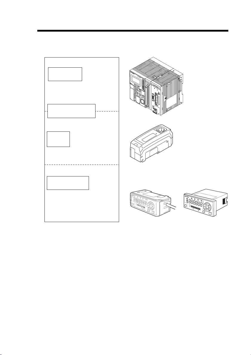
Relevant Manuals
PLC CPU unit
EtherNet/IP scanner
unit
DL-EP1 (this unit)
Manuals related
to CPU unit
Manuals related to
EtherNet/IP unit
This
manual
KV-DN20
MS
NS
ON
TERM.
Sensor amplifiers
Manuals for each
sensor amplifier unit
Example) · GT2-70/GT2-100 series
user's manual
The manuals relevant to this document are as follows:
- EtherNet/IP Compatible Network Unit DL-EP1 User’s Manual (GT2) -
3
Page 6

MEMO
4
- EtherNet/IP Compatible Network Unit DL-EP1 User’s Manual (GT2) -
Page 7

Manual Organization
Before Using
1
Connection and
Configuration
2
Communicating
with the GT2
Series
3
4
5
Specifications
Appendix
This chapter provides an overview of the DL-EP1
and describes its part names and functions.
This chapter describes the procedures from
installing the DL-EP1 and sensor amplifiers to
configuring communication.
This chapter describes the configuration of memory
that communicates with the EtherNet/IP compatible
network unit and a communication timing chart.
This chapter describes the specifications and
external dimensions of the DL-EP1.
This chapter provides the parameter list, as well as
troubleshooting instructions.
1
2
3
4
5
- EtherNet/IP Compatible Network Unit DL-EP1 User’s Manual (GT2) -
5
Page 8

Table of Contents
Safety Information for DL-EP1 ..................................................................... 1
General Precautions ......................................................................... 1
Precautions for Use ........................................................................... 1
Precautions on Regulations and Standards ...................................... 2
Relevant Manuals .......................................................................................... 3
Manual Organization ..................................................................................... 5
Table of Contents .......................................................................................... 6
Terms Used in This Document ..................................................................... 8
Chapter 1 Before Using
1-1 DL-EP1 Overview ..............................................................................1-2
Overview ........................................................................................1-2
Connectable Sensor Amplifiers ...................................................... 1-2
1-2 Checking the Package Contents .....................................................1-4
Package Contents ..........................................................................1-4
1-3 Names and Functions of Each Part ................................................. 1-5
Chapter 2 Connection and Configuration
2-1 Procedures from Installation before Using the DL-EP1 to
Configuration .................................................................................... 2-2
Configuration Procedures .............................................................. 2-2
2-2 Installation and Connection to Sensor Amplifiers .........................2-3
Mounting and connection to Sensor Amplifiers .............................. 2-3
Assigning ID Numbers ................................................................... 2-6
2-3 Wiring .................................................................................................2-8
Connecting a communication cable ............................................... 2-8
2-4 Configuring Communication with the DL-EP1 .............................2-10
DL-EP1 Settings ...........................................................................2-10
2-5 Configuring Communication with the Scanner ............................2-13
Setting the scanner ......................................................................2-13
Chapter 3 Communicating with the GT2 Series
3-1 What is EtherNet/IP? ......................................................................... 3-2
What is EtherNet/IP? ...................................................................... 3-2
3-2 DL-EP1 EtherNet/IP Communication Function .............................. 3-3
Overview of Communication Methods ...........................................3-3
3-3 Cyclic communication ...................................................................... 3-5
Configuring Cyclic Communication ................................................ 3-6
6
- EtherNet/IP Compatible Network Unit DL-EP1 User’s Manual (GT2) -
Page 9

Actions which can be completed with Cyclic Communication ........ 3-6
Usable Connections ....................................................................... 3-7
Assignment to IN Area (DL-EP1 to Scanner) ................................. 3-8
Assignment to OUT Area (Scanner to DL-EP1) ........................... 3-15
Communication Methods .............................................................3-17
Checking the Device Compatibility ............................................... 3-20
3-4 Message Communication ............................................................... 3-21
Configuring Message Communication .........................................3-22
Actions which can be Completed with Message Communication
Objects and Services ...................................................................3-25
Objects Usable by DL-EP1 ..........................................................3-27
Basic Format and Processing Flow of Message Communication
Reading the DL Object Table ....................................................... 3-30
DL Object (Class ID:67H) .............................................................3-31
Using DL Object ........................................................................... 3-46
Chapter 4 Specifications
4-1 Specifications .................................................................................... 4-2
4-2 Data Processing Time ......................................................................4-3
4-3 Dimensions ........................................................................................ 4-5
Chapter 5 Appendix
... 3-22
... 3-28
5-1 Device Profile .................................................................................... 5-2
5-2 Troubleshooting ................................................................................ 5-3
5-3 Default Settings ................................................................................. 5-5
5-4 Procedures for Communicating with an Allen-Bradley
ControlLogix PLC .............................................................................5-6
Procedures for Communicating with an Allen-Bradley ControlLogix PLC ..... 5-6
Procedures for Communication with an Allen-Bradley SLC5/05 PLC
5-5 Objects Usable by DL-EP1 .............................................................5-17
List of Usable Objects ..................................................................5-17
Reading Each Object Table .........................................................5-18
Identity Object (Class ID: 01H) .....................................................5-19
Message Router Object (Class ID: 02H) ......................................5-22
Assembly Object (Class ID: 04H) ................................................. 5-23
Connection Manager Object (Class ID: 06H) ............................... 5-25
TCP/IP Interface Object (Class ID: F5H) ..................................... 5-27
Ethernet Link Object (Class ID: F6H) ...........................................5-31
5-6 Index .................................................................................................5-35
- EtherNet/IP Compatible Network Unit DL-EP1 User’s Manual (GT2) -
...5-12
7
Page 10

Terms Used in This Document
This document uses the following terms:
Ter m Description
Sensor A sensor amplifier
Scanner The EtherNet/IP scanner device
Adaptor The EtherNet/IP adaptor device
Main unit
Expansion unit
D-bus
PLC Programmable logic controller
Ladder program A program which controls the PLC
A sensor amplifier that has a power line and can operate
alone
A sensor amplifier that does not have a power line and must
be connected to a main unit
The name of KEYENCE's wiring-saving system for sensor
amplifiers
Supports GT2 Series high-accuracy digital contact sensors
and others
8
- EtherNet/IP Compatible Network Unit DL-EP1 User’s Manual (GT2) -
Page 11

Before Using
This chapter provides an overview of the DL-EP1 and describes its
part names and functions.
1-1 DL-EP1 Overview...............................................1-2
1-2 Checking the Package Contents ........................1-4
1-3 Names and Functions of Each Part....................1-5
1
- EtherNet/IP Compatible Network Unit DL-EP1 User’s Manual (GT2) -
1-1
Page 12
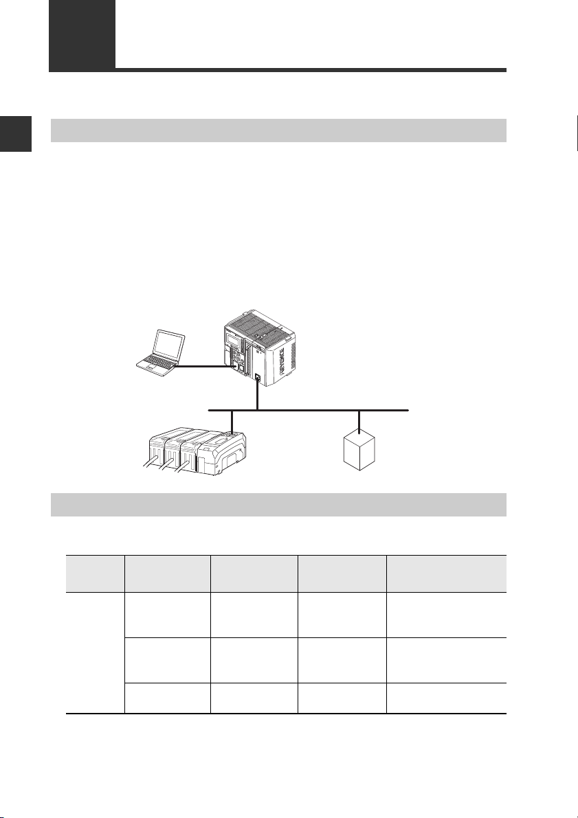
1-1
PLC or other host device
(EtherNet/IP unit)
DL-EP1 (this unit)
EtherNet/IP
adaptor
EtherNet
DL-EP1 Overview
1
Overview
Before Using
The DL-EP1 operates as an EtherNet/IP communication adaptor. EtherNet/IP
communications enable you to output the ON/OFF control signals and current values
of the DL-EP1 and sensor amplifiers connected to the DL-EP1 as communication
data to a PLC or other equipment.
The DL-EP1 supports EtherNet/IP cyclic communication (Implicit messaging) and
message communication (Explicit messaging). Cyclic communication enables data
exchange without a ladder program. Message communication allows for reading/
writing sensor amplifier parameters and issuing commands to the sensor amplifiers.
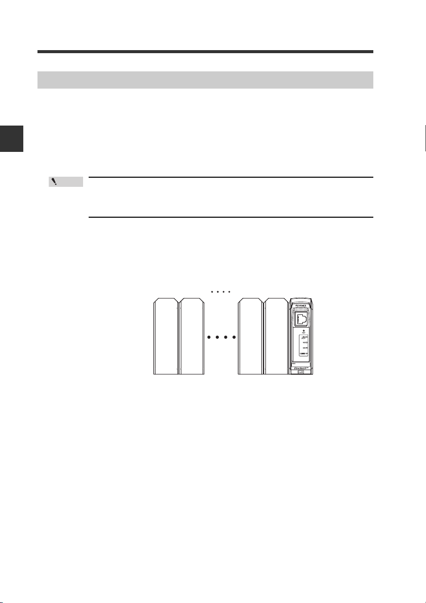
■ System configuration example
Connectable Sensor Amplifiers
■ Number of Connectable Sensor Amplifiers
Name Amplifier form Main unit
DIN rail mount
type
GT-2
Series
* Up to 11 sensor heads can be connected by adding a head connection board to
the main unit.
1-2
Panel mount
type
Large display
type
- EtherNet/IP Compatible Network Unit DL-EP1 User’s Manual (GT2) -
GT2-71(M)(C)N
GT2-71(M)(C)P
GT2-75N
GT2-75P
GT2-100N
GT2-100P
Expansion
unit
GT2-72(M)(C)N
GT2-72(M)(C)P
GT2-76N
GT2-76P
-
Maximum number of
connectable units
15
(1 main unit,
14 expansion units)
15
(1 main unit,
14 expansion units)
1
(1 main unit)*
Page 13

1-1 DL-EP1 Overview
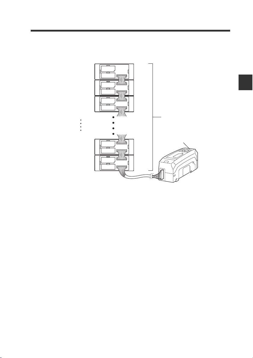
Sensor amplifiers supporting D-bus are connectable. You can connect one sensor to
the DL-EP1 as a main unit and one or more sensors to the main unit as expansion
units. (D-bus is the name of KEYENCE's wiring-saving system for sensor amplifiers.) If
the sensor amplifier is D-bus compatible, different models can be connected together.
How many and what types of sensor amplifiers can be connected depends on the
sensor amplifiers or units to be connected. Please inquire for details.
1
Before Using
- EtherNet/IP Compatible Network Unit DL-EP1 User’s Manual (GT2) -
1-3
Page 14

1
1-2
Before using the DL-EP1, make sure that the following equipment and accessories
are included in the package. We have thoroughly inspected the package contents
before shipment.
Before Using
However, in the event of defective or broken items, contact your nearest KEYENCE
office.
Package Contents
■ Package contents
DL-EP1 main unit x 1 Expansion connector
Instruction manual x 1
■ List of Optional Parts
• STP (shielded twisted pair) cable
(Category 5e, straight)
- OP-51504 (0.2m)
- OP-51505 (0.5m)
- OP-51506 (1m)
- OP-51507 (3m)
- OP-51508 (5m)
* The working ambient temperature of the above
cables are 0 to 50°C.
Checking the Package Contents
End unit x 2
sticker x 1
OP-26751
1-4
- EtherNet/IP Compatible Network Unit DL-EP1 User’s Manual (GT2) -
Page 15
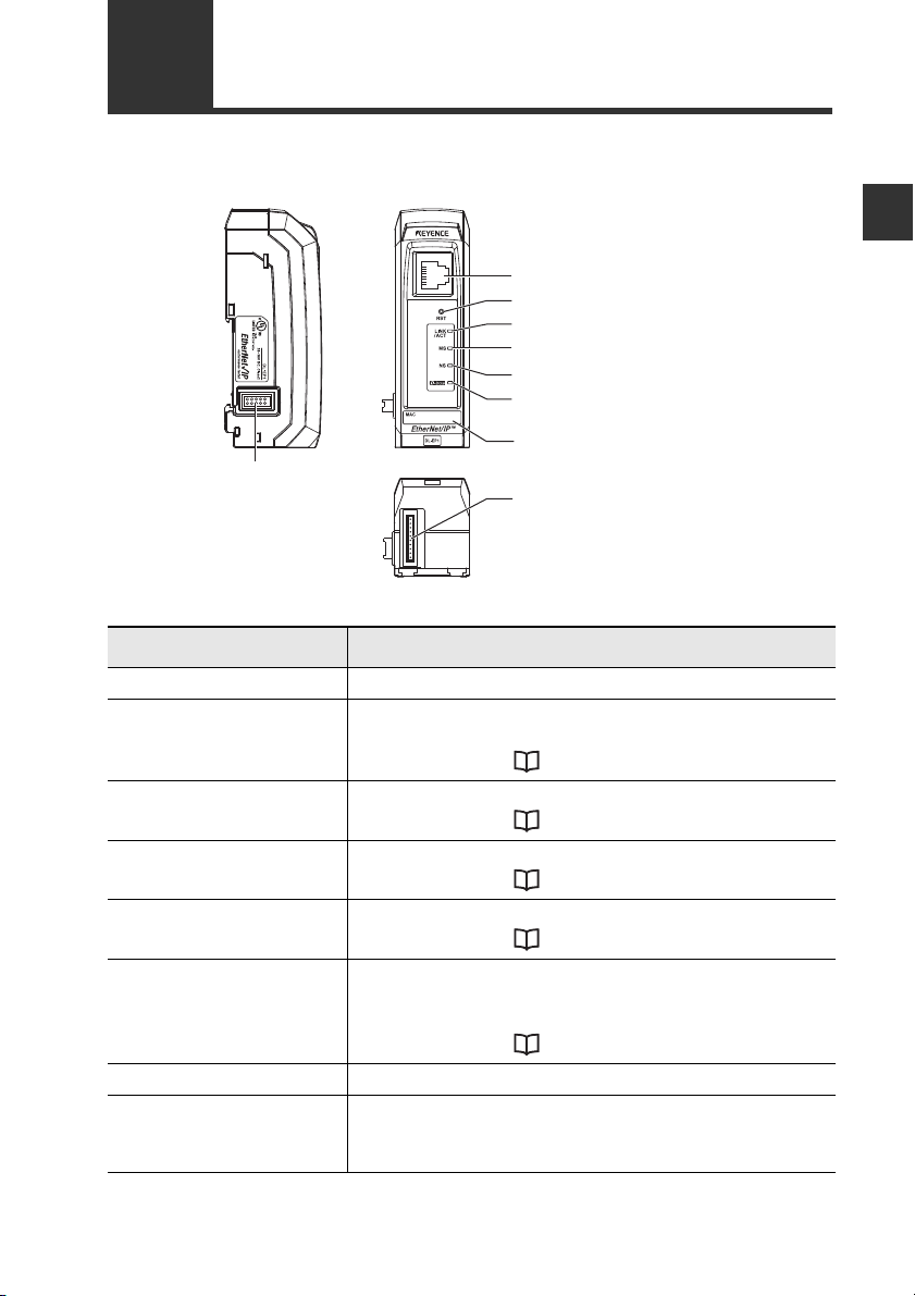
1-3
(8) Sensor amplifier connector
(for DIN rail mount type)
(1) RJ-45 connector
(2) Reset switch
(3) Link/activity indicator (green)
(4) Module status indicator (green/red)
(5) Network status indicator (green/red)
(6) Sensor communication indicator
(green/red)
(7) MAC address
(9) Sensor amplifier connector
(for panel mount type
and large display type)
This section describes the part names and functions of the DL-EP1.
(1) RJ-45 connector Attach the network cable to this connector.
(2) Reset switch When held down for three seconds or longer, the DL-EP1
(3) Link/activity
indicator
(4) Module status
indicator
(5) Network status
indicator
(6) Sensor communication
indicator
(7) MAC address MAC address for this DL-EP1
(8) Sensor amplifier
connector (for DIN rail
mount type)
Names and Functions of Each Part
Name Description
settings will be reset to the default settings.
For details, refer to "Default Settings" (Page 5-5).
Normal: Green LED lights up or blinks
For details, refer to "Troubleshooting" (Page 5-3).
Normal: Green LED lights up
For details, refer to "Troubleshooting" (Page 5-3).
Normal: Green LED lights up
For details, refer to "Troubleshooting" (Page 5-3).
Indicates the status of communication between the DLEP1 and sensor amplifiers.
Normal: Green LED lights up
For details, refer to "Troubleshooting" (Page 5-3).
Attach the sensor amplifier to this connector. When not
using this connector, remove it and replace with the
protective sticker.
- EtherNet/IP Compatible Network Unit DL-EP1 User’s Manual (GT2) -
1
Before Using
1-5
Page 16

1
1-3 Names and Functions of Each Part
Name Description
(9) Sensor amplifier
connector (for panel
Before Using
mount/large display
type)
Attach the sensor amplifier to this connector. A protective
seal is attached when shipped from the factory. The
optional expansion cable (OP-35361) is used for this
connection.
1-6
- EtherNet/IP Compatible Network Unit DL-EP1 User’s Manual (GT2) -
Page 17

Connection and Configuration
This section describes procedures from installing the DL-EP1 and
sensor amplifiers to configuring communication.
2-1 Procedures from Installation before Using the DL-EP1 to
Configuration...........................................................2-2
2-2
Installation and Connection to Sensor Amplifiers ...
2-3 Wiring ................................................................. 2-8
2-4 Configuring Communication with the DL-EP1..2-10
2-5 Configuring Communication with the Scanner . 2-13
2-3
2
- EtherNet/IP Compatible Network Unit DL-EP1 User’s Manual (GT2) -
2-1
Page 18
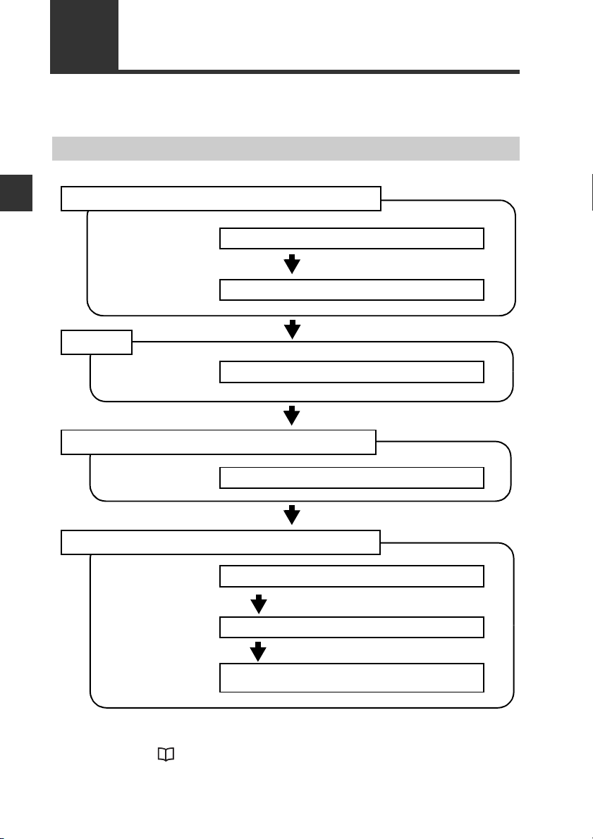
2-1
1. Installation and Connection to Sensor Amplifiers
Connecting the DL-EP1 to sensor amplifiers (Page 2-4)
Assigning ID Numbers (Page 2-6)
2. Wiring
3. Configuring Communication with the DL-EP1
4. Configuring Communication with the Scanner
Connecting a communication cable (Page 2-8)
Setting the IP address (Page 2-10)
Setting the IP address (Page 2-13)
Registering the device profile of the DL-EP1
(Page 2-13)
Configuring the Scanner Side
(Refer to each scanner manual.)
This section describes the procedures before you use the DL-EP1.
Procedures from Installation before Using the DL-EP1 to Configuration
Configuration Procedures
2
Connection and Configuration
The above configurations enable communication.
For the outline of scanner side configuration for communication with an Allen-Bradley
scanner, refer to "Procedures for Communicating with an Allen-Bradley
ControlLogix PLC" (Page 5-6).
2-2
- EtherNet/IP Compatible Network Unit DL-EP1 User’s Manual (GT2) -
Page 19

2-2
(3)
(2)
(1)
Number of Connectable Sensor Amplifiers
Installation and Connection to Sensor Amplifiers
Name Amplifier form Main unit
DIN rail mount
type
GT-2
Series
* Up to 11 sensor heads can be connected by adding a head connection board to
the main unit.
This section describes how to mount the DL-EP1 on the DIN rail and to connect it to
sensor amplifiers.
Sensor amplifiers supporting D-bus are connectable. You can connect one sensor to
the DL-EP1 as a main unit and one or more sensors to the main unit as expansion
units. (D-bus is the name of KEYENCE's wiring-saving system for sensor amplifiers.)
If the sensor amplifier is D-bus compatible, different models can be connected
together.
How many and what types of sensor amplifiers can be connected depends on the
sensor amplifiers or units to be connected. Please inquire for details.
Panel mount
type
Large display
type
GT2-71(M)(C)N
GT2-71(M)(C)P
GT2-75N
GT2-75P
GT2-100N
GT2-100P
Expansion
unit
GT2-72(M)(C)N
GT2-72(M)(C)P
GT2-76N
GT2-76P
-
Maximum number of
connectable units
15
(1 main unit,
14 expansion units)
15
(1 main unit,
14 expansion units)
1
(1 main unit)*
Mounting and connection to Sensor Amplifiers
2
Connection and Configuration
Mounting the DL-EP1 on the DIN rail
Align the claw on the bottom of the DL-EP1 with the DIN rail. While
1
pushing the amplifier in the direction of arrow (1), press down in the
direction of arrow (2).
To remove the DL-EP1, raise the amplifier in the direction of arrow (3)
2
while pushing the DL-EP1 in the direction of arrow (1).
- EtherNet/IP Compatible Network Unit DL-EP1 User’s Manual (GT2) -
2-3
Page 20
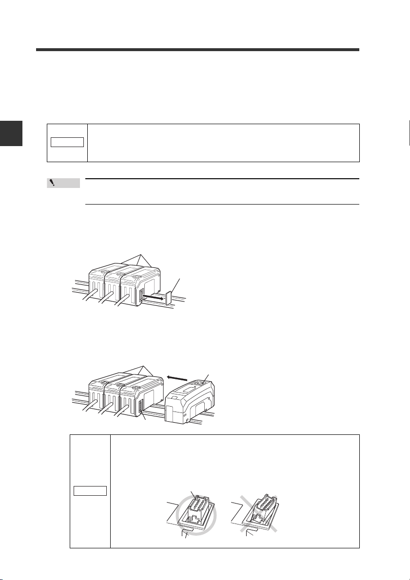
2-2 Installation and Connection to Sensor Amplifiers
Point
Sensor amplifier
Expansion protective cover
Sensor amplifier
EtherNet/IP Compatible Network Unit
DL-EP1
Connector
NOTICE
Sensor amplifier connector
EtherNet/IP Compatible Network Unit DL-EP1
Connecting the DL-EP1 to sensor amplifiers
The EtherNet/IP Compatible Network Unit DL-EP1 must be connected to sensor
amplifiers before it can function.
The connecting procedure varies with the mounting type of the sensor amplifiers to
be connected.
2
Connection and Configuration
Make sure that the sensor amplifiers are turned off before
NOTICE
z Connecting to sensor amplifiers of the DIN rail mount type
1
2
connecting the EtherNet/IP Compatible Network Unit DL-EP1.
Connecting the DL-EP1 to the sensor amplifiers when they are
turned on may damage the DL-EP1.
For the instructions on connecting additional sensor amplifiers, refer to the
instruction manual of each sensor amplifier.
Remove the expansion protective cover from the sensor amplifier to be
connected.
Mount the EtherNet/IP Compatible Network Unit DL-EP1, on the DIN rail
and connect it to the sensor amplifier.
Insert the EtherNet I/P Compatible Network Unit DL-EP1 to the sensor amplifier
connector so as not to leave space between them.
2-4
- EtherNet/IP Compatible Network Unit DL-EP1 User’s Manual (GT2) -
Make sure that the sensor amplifier connector (for DIN rail mount
type) is not askew on the side face of the EtherNet/IP Compatible
Network Unit DL-EP1 according to the figure shown below.
Connecting the DL-EP1 to the sensor amplifier with the connector
being askew may damage the DL-EP1.
Page 21
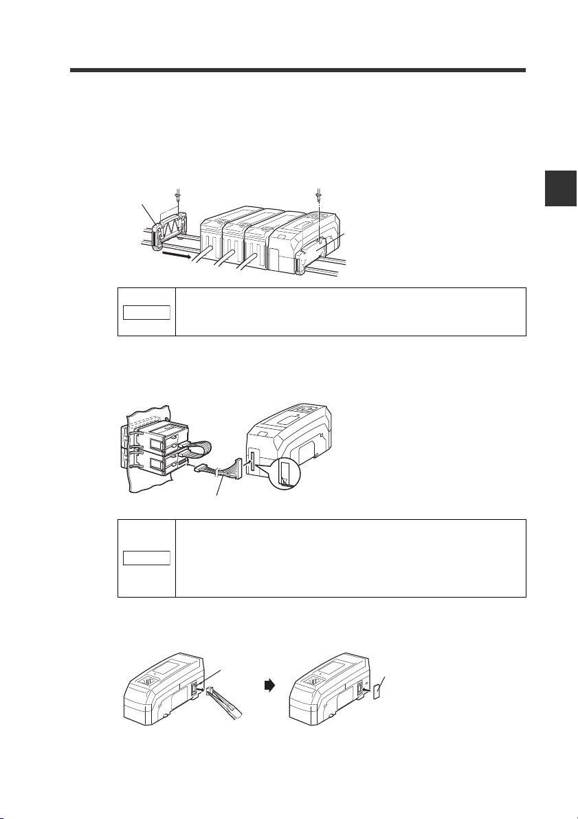
2-2 Installation and Connection to Sensor Amplifiers
NOTICE
Peel off the protective sticker.
Expansion cable (Cable length: 300 mm)
NOTICE
Sensor amplifier connector
(for DIN rail mounting type)
Expansion
connector sticker
Mount the supplied end units (OP-26751: a set of two pieces) on the outer
3
ends of the amplifier and the EtherNet/IP Compatible Network Unit DLEP1. Then, fix the end units with the screws on the top of each end unit (2
points x 2 units). (Tightening torque : 0.6 N•m or less)
Mount the end units in the same way as the EtherNet/IP Compatible Network
Unit DL-EP1.
End unit
End unit
Press the EtherNet/IP Compatible Network Unit DL-EP1, into
full engagement with the sensor amplifier. Energizing the DLEP1 when not inserted fully may damage the DE-EP1.
z Connecting to sensor amplifiers of panel mount type
Connect the sensor amplifier and the EtherNet/IP Compatible Network
1
Unit DL-EP1, with the optional expansion cable (OP-35361).
2
Connection and Configuration
• Turn off the power supply and connect the expansion cable
securely. Energizing the DL-EP1 when not inserted fully
may damage the DL-EP1.
• Attaching or detaching the cable when the power supply is
on may damage the DL-EP1.
Remove the sensor amplifier connector (for DIN rail mount type) from the
2
EtherNet/IP Compatible Network Unit DL-EP1 using pliers. Then, attach
the expansion connector sticker supplied with the DL-EP1.
- EtherNet/IP Compatible Network Unit DL-EP1 User’s Manual (GT2) -
2-5
Page 22
2
Point
ID number 01
Main
unit
Expansion
unit
Expansion
unit
Expansion
unit
02 14 15 00
2-2 Installation and Connection to Sensor Amplifiers
Assigning ID Numbers
Several sensor amplifiers can be connected to the DL-EP1. ID numbers for data
identification are assigned to each sensor amplifier.
The method for assigning ID numbers is as follows:
• ID numbers are assigned in order, starting from the sensor amplifier that is the
main unit. (Optional numbers cannot be assigned.)
Connection and Configuration
• 0 is assigned as the ID number of the DL-EP1.
• You cannot change the ID numbers assigned to the sensor amplifiers.
• In this manual, ID number 00 to ID number 15 are denoted as ID00 to
ID15, respectively.
Also for cyclic communication, output, current value, and external input are assigned
one by one per ID number.
For DIN rail mount type
2-6
- EtherNet/IP Compatible Network Unit DL-EP1 User’s Manual (GT2) -
Page 23
For panel mount type
2-2 Installation and Connection to Sensor Amplifiers
ID number
01
02
03
14
15
Sensor amplifier
Main unit
Expansion unit
Expansion unit
Sensor amplifier
Expansion unit
Expansion unit
DL-EP1
ID number 00
2
Connection and Configuration
- EtherNet/IP Compatible Network Unit DL-EP1 User’s Manual (GT2) -
2-7
Page 24

2
STP/UTP cable
Point
2-3
Connecting a communication cable
Connection and Configuration
Usable cable
Wiring
The DL-EP1 uses the power supplied to sensor amplifiers, so there is no power cable
wiring. This section describes the wiring of communication cables used by the DLEP1.
Use the following procedures to connect the DL-EP1 to the communication cable
required for EtherNet/IP communication.
Usable cables depend on whether the system is configured with 10BASE-T or
100BASE-TX.
Structuring a 10BASE-T system
When the system is configured
with 10BASE-T, use a Category
3 or higher shielded twisted-pair
(STP) cable or an unshielded
twisted-pair (UTP) cable.
Structuring a 100BASE-TX
network
When the system (network) is configured with 100BASE-TX, use a Category 5 or
higher STP or UTP cable. Do not use a Category 3 or Category 4 UTP cable.
2-8
• Use a STP/UTP straight cable when connecting the DL-EP1 to an
Ethernet switch.
• Use a STP/UTP cross cable when directly connecting the DL-EP1 to a
PC.
• Do not use the STP/UTP cross cable incorrectly because it is difficult to
distinguish this cable from the STP/UTP straight cable in appearance.
• When the system (Ethernet) is configured with a type (e.g., 10BASE-2
or 10BASE-5) other than 10BASE-T and 100BASE-TX, use an Ethernet
switch with an AUI (MAU) connector or a BNC connector or use a media
converter (10BASE5 → 10BASE-T or 10BASE2 → 10BASE-T).
- EtherNet/IP Compatible Network Unit DL-EP1 User’s Manual (GT2) -
Page 25

2-3 Wiring
NOTICE
Point
DL-EP1 connector port
The DL-EP1 connector port accepts an RJ-45 8-pole modular connector (ISO8877
compliant) used with 10BASE-T and 100BASE-TX and complies with the IEEE802.3
Standards.
Precautions for connecting a STP/UTP cable to the DL-EP1 connector port
Take care not to apply a load to the DL-EP1 connector port when connecting the
STP/UTP cable to the DL-EP1.
The cable may be bent and used when installed. Bending the cable
at a sharp angle may cut the wires in the cable or the cable may be
disconnected during use. Install or lay the cable to be used with
attention to the recommended bending radius R of the cable.
Connecting the DL-EP1 to EtherNet/IP
The following describes how to connect the DL-EP1 to the RJ-45 connector.
Turn off the power supply.
1
Connect one modular jack of the STP/UTP cable to the 10BASE-T/
2
100BASE port of the Ethernet switch to be used.
Insert the modular jack until a "click" is heard. The modular jack and connector
will lock.
2
Connection and Configuration
・ Keep the length of the STP/UTP cable to be used 100 m or less.
・ Carefully check the state of connector (port) on the Ethernet
switch before connecting the DL-EP1. There are various Ethernet
switches. Some Ethernet switches have a different shape
connector (AUI connector or BNC connector, etc.) from the RJ-45,
while some have connectors used to connect Ethernet switches
together (cascade ports).
Connect the modular jack on the other end of the STP/UTP cable to the
3
DL-EP1 connector port.
Insert the jack until a "click" is heard. The modular jack and connector will lock.
- EtherNet/IP Compatible Network Unit DL-EP1 User’s Manual (GT2) -
2-9
Page 26
2-4
This section describes settings for connecting the DL-EP1 to the EtherNet/IP system.
Configuring Communication with the DL-EP1
DL-EP1 Settings
The following describes how to set communication with the DL-EP1.
2
Setting the IP address
Connection and Configuration
Set the IP address with the DL-EP1 wired and with the power supplied.
By default, the IP address is not set. However, you can use the BOOTP client function
to set the IP address via Ethernet.
The following 2 methods are available for setting the IP address.
• Use the IP address setting tool (this tool can be downloaded from the Keyence
web site http://www.keyence.com).
Refer to the following setting procedures or the "IP Setting Tool User's Manual".
• Use an IP address setting tool from other sources.
Refer to the manuals provided by the respective sources.
z Using the IP address setting tool
Here briefly describes the procedures for setting the IP address with the IP
address setting tool. For details on how to use the IP address setting tool, refer to
the "IP Setting Tool User's Manual". You can view the "IP Setting Tool User's
Manual" from [Help(H)] of "IP Setting Tool" as the PDF file.
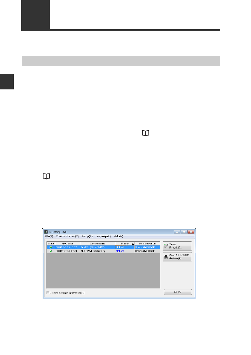
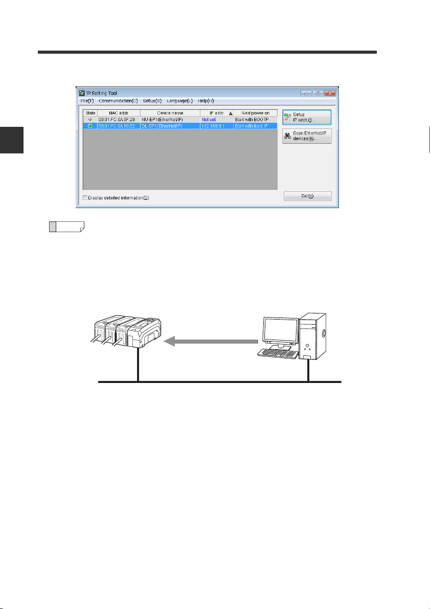
Start the IP Setting Tool.
1
Devices such as the DL-EP1 connected to the network and for which their IP
addresses are not set will appear.
To display the devices for which their IP addresses are set, click the [Scan
EtherNet/IP devices (A)] button.
2-10
- EtherNet/IP Compatible Network Unit DL-EP1 User’s Manual (GT2) -
Page 27
2-4 Configuring Communication with the DL-EP1
Reference
Point
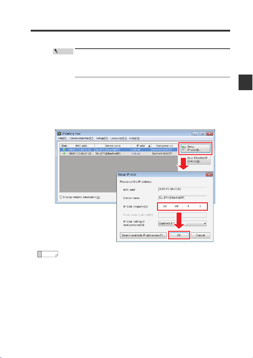
To display "Not Set" for the IP address, the network status indicator
(NS) must be off (IP address not assigned). To unassign the IP
address, hold down the Reset switch on the DL-EP1 for three
seconds or longer.
Select the device for which to set the IP address and click [Setup IP addr.(I)] to
2
display [Setup IP addr.].
Compare the MAC address to be displayed with the front MAC address on the
DL-EP1 and select the device for which to set the IP address.
Set an IP address which is not currently used in "IP addr.(required)(I)" and click
the [OK] button.
2
Connection and Configuration
Using the [Search available IP addresses (F)] button enables you to
search for open IP addresses.
- EtherNet/IP Compatible Network Unit DL-EP1 User’s Manual (GT2) -
2-11
Page 28
2
Reference
IP address assignment
BOOTP client BOOTP server
Via Ethernet
Ethernet
2-4 Configuring Communication with the DL-EP1
The IP address has now been set.
3
Connection and Configuration
What is BOOTP?
BOOTP is the abbreviation of BOOT strap Protocol. This protocol is used
by the client device in the TCP/IP network to make the network settings
assigned from the server.
If there is a BOOTP server in the same network as the device running as
the BOOTP client, an IP address is assigned to the device connected as
the BOOTP client.
2-12
- EtherNet/IP Compatible Network Unit DL-EP1 User’s Manual (GT2) -
Page 29

2-5
Reference
This section describes scanner side configuration for connecting the DL-EP1 to the
EtherNet/IP system.
When communicating with an Allen-Bradley scanner, also refer to the
"Procedures for Communicating with an Allen-Bradley ControlLogix PLC" (Page 5-6).
Configuring Communication with the Scanner
Setting the scanner
Connecting the DL-EP1 to the EtherNet/IP scanner requires the following settings:
Setting the IP address
Set the IP address of the scanner.
Registering the device profile of the DL-EP1
Register the device profile of the adaptor (DL-EP1) to be connected using the
scanner's setting software.
You can register the device profile manually or by reading the EDS (Electronic Data
Sheet) file. You can download the EDS file of the DL-EP1 from the Keyence web site
(http://www.keyence.com).
Configuring communication with the DL-EP1
The DL-EP1 uses EtherNet/IP cyclic communication or message communication to
communicate with the scanner.
z Cyclic communication (Implicit messaging)
This function sends and receives data at a set RPI (Requested Packet Interval).
Selecting the communication method called "connection" and assigning the
devices to be sent and received on the scanner side enables the DL-EP1 to
communicate with the scanner without creating a ladder program.
z Message communication (Explicit messaging)
This function is used to send and receive data which does not need to be timed.
Use this function when changing the sensor amplifier settings or when performing
EtherNet/IP communication with the scanner (e.g., Allen-Bradley SLC5/05 Series)
that does not support cyclic communication.
This function uses a ladder program to create a message on the scanner side for
communication.
2
Connection and Configuration
For more information on setting each communication method, refer to the chapters
titling "Communicating with...." of each sensor amplifier as well as the manuals
enclosed with each scanner.
This manual explains only the EtherNet/IP scanner functions and settings
required for communication with the DL-EP1. For details on the functions
and settings between the EtherNet/IP scanner and CPU unit, refer to the
manuals enclosed with the scanner and CPU unit.
- EtherNet/IP Compatible Network Unit DL-EP1 User’s Manual (GT2) -
2-13
Page 30

2
2-5 Configuring Communication with the Scanner
MEMO
Connection and Configuration
2-14
- EtherNet/IP Compatible Network Unit DL-EP1 User’s Manual (GT2) -
Page 31

Communicating with
the GT2 Series
This chapter describes the configuration of memory that
communicates with the EtherNet/IP compatible network unit
and a communication timing chart.
3-1 What is EtherNet/IP?..........................................3-2
3-2 DL-EP1 EtherNet/IP Communication Function .. 3-3
3-3 Cyclic communication......................................... 3-5
3-4 Message Communication................................. 3-21
3
- EtherNet/IP Compatible Network Unit DL-EP1 User’s Manual (GT2) -
3-1
Page 32

3
Scanner
Adaptor Adaptor Adaptor
High speed
(Communication cycle: 10 ms)
Regular speed
(Communication
cycle: 100 ms)
Low speed (Communication cycle: 1000 ms)
3-1
What is EtherNet/IP?
What is EtherNet/IP?
EtherNet/IP is an industrial communication network with open specifications. The
specifications are managed by ODVA (Open DeviceNet Vendor Association, Inc.).
Industrial protocol has been combined with the Ethernet and standardized as EtherNet/IP (Industrial Protocol).
Communication is realized by combining the protocols known as Common Industrial
Protocol (CIP) with TCP/IP and Ethernet. This allows regular Ethernet to be used
together with the network.
Communicating with the GT2 Series
Before starting EtherNet/IP communication, one of the devices must open a
communication line called a "connection" with the other device. The side which
opens the connection is called the "scanner", and the side to be opened is called the
"adaptor". (The DL-EP1 is an adaptor.)
EtherNet/IP includes cyclic communication (Implicit messaging) which sends and
receives data periodically. Message communication (Explicit messaging) which
sends and receives commands and responses at a time specified by the user.
Cyclic communication enables you to set RPI (Requested Packet Interval) according
to the priority of the data to be exchanged, allowing the entire communication load to
be adjusted for data exchange.
Message communication enables you to exchange the required commands and
responses at the required timing. Message communication is used for applications
which do not require the punctuality of cyclic communication, such as reading and
writing adaptor settings.
3-2
- EtherNet/IP Compatible Network Unit DL-EP1 User’s Manual (GT2) -
Page 33

3-2
Output
Comparator Value
・・・・・・
Error information
External input
Setting value
Output
Comparator Value
・・・・・・
Error information
External input
Setting value
IN area
OUT area
Output
Current value
Error information
External input
EtherNet/IP scanner
DL-EP1
Sensor amplifier
Message communication
Output
Comparator Value
・・・・・・
Error information
IN area
OUT area
Direct read/write of various parameters
Cyclic communication
External input
Setting value
Cyclic communication
DL-EP1 EtherNet/IP Communication Function
This section describes the EtherNet/IP functions supported by the DL-EP1.
The DL-EP1 functions as an EtherNet/IP adaptor, and supports both cyclic and
message EtherNet/IP communications.
Overview of Communication Methods
3
Communicating with the GT2 Series
Cyclic communication
The EtherNet/IP scanner can use the following functions:
Communication Methods
Function of sensor amplifier
Read status
Read output
Read current value
Execute external input
Change bank number
Rewrite setting value
Motion command
Read current value, setting, and
status
Read number of decimal places
Rewrite setting value
Lock all
Cyclic communication
(Page 3-5)
{
X
Message Communication
(Page 3-21)
{
This function sends and receives data between the scanner and DL-EP1 at the set
RPI (Requested Packet Interval). The function can exchange data such as the
- EtherNet/IP Compatible Network Unit DL-EP1 User’s Manual (GT2) -
3-3
Page 34

3
PLC
EtherNet/IP scanner
RPI=3 (ms)*
RPI=0.5 (ms)*
RPI=5 (ms)*
RPI=10 (ms)*
Various EtherNet/IP adaptors
Ethernet
* RPI (Requested Packet Interval) can be set
individually for each connection.
Point
3-2 DL-EP1 EtherNet/IP Communication Function
sensor amplifier's output signals and comparator values and error status without
ladder programs.
Communicating with the GT2 Series
Configurations such as RPI and data size for cyclic communication are set
on the scanner side.
In a network which has many connected devices, including EtherNet/IP
devices, a delay or packet loss could occur if a large load is constantly or
temporarily applied on the network. Verify the settings carefully before
operation.
Message communication
Message communication can be used for applications which do not require a
punctuality like cyclic communication.
In message communication, various parameters, including data which can be
exchanged with cyclic communication, can be read and written. Functions specific
to sensors such as the sensor amplifier preset function can also be executed.
3-4
- EtherNet/IP Compatible Network Unit DL-EP1 User’s Manual (GT2) -
Page 35

3-3
(1) Request connection open
(3) Open connection
(2) Check
compatibility
Output data
Data reflected in the
scanner
Input data
The data output from the
scanner is stored by the
DL-EP1.
EtherNet/IP scanner DL-EP1 Sensor amplifier
IN area
OUT area
Cyclic communication
Data between
sensors is
refreshed
Cyclic
communication
Data between
sensors is
refreshed
Reference
Cyclic communication
This section describes the cyclic communication functions and how to use them.
What is cyclic communication?
Cyclic communication is a function that exchanges data with the EtherNet/IP device
in a cyclic manner (at a set cycle).
In cyclic communication, data can be exchanged when one device successfully
opens a logical communication line called a "connection" with the other device.
The side which opens the connection is called the scanner, and the side to be
opened is called the adaptor. (The DL-EP1 is an adaptor.)
Cyclic communication is started in the following procedures:
(1) The scanner requests the adaptor to open the connection.
(2) The adapter side checks compatibility.
(3) If no error occurs as a result the compatibility check, the adapter opens the
connection.
(* If an error is found during the compatibility check, the adapter does not open
the connection.)
"Checking the Device Compatibility" (Page 3-20)
Data is exchanged between the EtherNet/IP scanner, DL-EP1 and each sensor
amplifier as follows:
3
Communicating with the GT2 Series
To carry out EtherNet/IP communication with a scanner which does not
support cyclic communication (Allen-Bradley SLC5/05 Series, etc.), use
"Message Communication" (Page 3-21).
- EtherNet/IP Compatible Network Unit DL-EP1 User’s Manual (GT2) -
3-5
Page 36

3-3 Cyclic communication
Configuring Cyclic Communication
The following settings are required to execute cyclic communication with the DLEP1.
[DL-EP1]
The DL-EP1 does not require any setting.
3
Communicating with the GT2 Series
[Scanner]
(1) Set the connection to be used.
(2) Set the devices used in cyclic communication.
Refer to the scanner manual for details on how to make the above settings.
(* No ladder program is required when cyclic communication is used.)
Actions which can be completed with Cyclic Communication
Cyclic communication can use the following functions:
(1) Read status
(2) Read output (Page 3-17)
Outputs that can be read: HIGH output, LOW output, GO output, HH output, LL
output
(3) Read P.V. value (Page 3-19)
(4) Execute external input (Page 3-18)
Inputs that can be used: PRESET, TIMING, RESET, error clear
3-6
- EtherNet/IP Compatible Network Unit DL-EP1 User’s Manual (GT2) -
Page 37

3-3 Cyclic communication
Reference
Usable Connections
EtherNet/IP requires that a connection must be opened from the scanner when cyclic
communication is started. There are various types of connections, and the type
usable by each device is defined in the EDS file.
The DL-EP1 can use the following connections:
No
Monitor Data
And External
1
Input
Monitor Data
2
(Input Only)
Connection
Name
Input/Output
DL-EP1 to scanner 64H (100) 168
Scanner to
DL-EP1
DL-EP1 to scanner 64H (100) 168
Scanner to
DL-EP1
Assembly
Instance
65H (101) 10
FEH (254) 0
Size
(Byte)
RPI Range
(in 0.5 ms)
0.5 ms to
10000 ms
0.5 ms to
10000 ms
Application
Exclusive
Owner
Input Only
・ Each connection's trigger timing is executed cyclically. The connection
type supports both point-to-point and multicast.
・ The details of each application type are as follows:
Exclusive Owner:
This connection allows simultaneous setting of both data
transmission from the scanner to the DL-EP1 and data
transmission from the DL-EP1 to the scanner. This setting is
made not only when the scanner monitors the adaptor (DL-EP1)
data, but also when it issues external inputs and rewrites the
settings, etc. Multiple "Exclusive Owner" connections cannot be
opened to one adaptor (DL-EP1).
Input Only:
This connection allows only data transmission from the DL-EP1
to the scanner. This setting is made when the scanner only
monitors adaptor (DL-EP1) data. Multiple scanners can open an
"Input Only" connection simultaneously to one adaptor (DLEP1).
(* To simultaneously open connections from multiple scanners,
set the Connection Type to Multicast.
Ty pe
3
Communicating with the GT2 Series
- EtherNet/IP Compatible Network Unit DL-EP1 User’s Manual (GT2) -
3-7
Page 38

3
DL-EP1 data
Scanner IN area
Address 0
Address 1
Address 167
Monitor Data
(Assembly Instance: 100)
1-byte (8-bit) data
Reference
16-bit data
Address 40 to 41
16-bit data
Address 42 to 43
12H 34H
56H 78H
High-order byte Low-order byte
High-order byte Low-order byte
56H
43
78H4212H4134H
40
32-bit data
Address 48 to 51
12H
51
34H5056H4978H
48
12H 34H 56H 78H
3-3 Cyclic communication
Assignment to IN Area (DL-EP1 to Scanner)
The data from the DL-EP1 is assigned to the EtherNet/IP scanner's IN area.
Communicating with the GT2 Series
The data such as 16-bit data extending over multiple bytes is stored into
an area which starts with an even address in order from the lowest-order
byte.
Example)
3-8
- EtherNet/IP Compatible Network Unit DL-EP1 User’s Manual (GT2) -
Page 39

3-3 Cyclic communication
Monitor Data (84 Words (168 Bytes)) Assembly Instance (Instance ID): 64H
This is the device map for the monitor data to be assigned to the IN area.
For details on each parameter, refer to "Parameter List" (Page 3-11).
For details on current value 0 and current value 1, refer to "Current Value 0/
Current Value 1" (Page 3-12).
ID numbers (ID01 to ID15) are assigned for each sensor amplifier according to the
number of sensor amplifiers. The ID numbers representing unconnected sensor
amplifiers are not assigned.
Name
Status
Sensor
Error
Status
Sensor
Warning
Status
Current
Valu e 0
Over
Range
Current
Valu e 0
Under
Range
Current
Valu e 0
Invalid
Current
Valu e 1
Over
Range
Current
Valu e 1
Under
Range
Current
Valu e 1
Invalid
Output 1
(HIGH)
Output 2
(LOW)
Output 3
(GO)
Output 4
(HH)
Address
(Byte)
0
1 Error Status
2 ID08 . . . . . ID01
3
4 ID08 . . . . . ID01
5
6 ID08 . . . . . ID01
7
8 ID08 . . . . . ID01
9
10 ID08 . . . . . ID01
11
12 ID08 . . . . . ID01
13
14 ID08 . . . . . ID01
15
16 ID08 . . . . . ID01
17
18 ID08 . . . . . ID01
19
20 ID08 . . . . . ID01
21
22 ID08 . . . . . ID01
23
24 ID08 . . . . . ID01
25
bit7 bit6 bit5 bit4 bit3 bit2 bit1 bit0
Reserved for system
Reserved for
system
Reserved for
system
Reserved for
system
Reserved for
system
Reserved for
system
Reserved for
system
Reserved for
system
Reserved for
system
Reserved for
system
Reserved for
system
Reserved for
system
Reserved for
system
Warning
Status
ID15 . . . . . ID09
ID15 . . . . . ID09
ID15 . . . . . ID09
ID15 . . . . . ID09
ID15 . . . . . ID09
ID15 . . . . . ID09
ID15 . . . . . ID09
ID15 . . . . . ID09
ID15 . . . . . ID09
ID15 . . . . . ID09
ID15 . . . . . ID09
ID15 . . . . . ID09
Reserved for system
- EtherNet/IP Compatible Network Unit DL-EP1 User’s Manual (GT2) -
DL-EP1
Error Status
3
Communicating with the GT2 Series
3-9
Page 40

3-3 Cyclic communication
3
Communicating with the GT2 Series
Name
Output 5
(LL)
External
Input
Response 1
(Preset)
External
Input
Response 2
(Timing)
External
Input
Response 3
(Preset)
External
Input
Response 4
(Error
Clear)
External
Input
Response 5
(Unassigned)
Error
ID Number
Error
Code
Warning
ID Number
Warning
Code
Current
Val ue 0
(
Comparator
Value (P.V.)
or Raw
Value (R. V.))
Current
Val ue 1
(
Unassigned
Address
(Byte)
26 ID08 . . . . . ID01
27
28 ID08 . . . . . ID01
29
30 ID08 . . . . . ID01
31
32 ID08 . . . . . ID01
33
34 ID08 . . . . . ID01
35
36 ID08 . . . . . ID01
37
40
41
42
43
44
45
46
47
48
49
50
51
::
104
105
106
107
108
109
110
111
::
)
164
165
166
167
bit7 bit6 bit5 bit4 bit3 bit2 bit1 bit0
Reserved for
system
Reserved for
system
Reserved for
system
Reserved for
system
Reserved for
system
Reserved for
system
ID15 . . . . . ID09
ID15 . . . . . ID09
ID15 . . . . . ID09
ID15 . . . . . ID09
ID15 . . . . . ID09
ID15 . . . . . ID09
Current Error ID Number (16-bit unsigned integer)
Current Error Code (16-bit unsigned integer)
Current Warning ID Number (16-bit unsigned integer)
Current Warning Code (16-bit unsigned integer)
ID Number 1 (Current Value 0) (32-bit signed integer)
ID Number 15 (Current Value 0) (32-bit signed integer)
ID Number 1 (Current Value 1) (32-bit signed integer)
ID Number 15 (Current Value 1) (32-bit signed integer)
3-10
- EtherNet/IP Compatible Network Unit DL-EP1 User’s Manual (GT2) -
Page 41

Parameter List
Item Description
DL-EP1 Error
Status
Warning Status (Unassigned)
Error Status
Sensor Error Status
Sensor Warning
Status
Current Value n
Over Range
(n: 0 to 1)
Current Value n
Under Range
(n: 0 to 1)
Current Value n
Invalid
(n: 0 to 1)
Output n (n: 1 to 5)
External Input
Response
n (n: 1 to 5)
The error status of the DL-EP1 is output.
ON: An error occurred.
OFF: No error occurred.
The error status of the DL-EP1 or the error statuses of all the connected sensor
amplifiers are output.
When ON, a value is stored in "Error ID Number" and "Error Code". When OFF, 0
is stored in "Error ID Number" and "Error Code".
ON: An error occurred in the DL-EP1 or in any of the connected sensor
amplifiers.
OFF: No error occurred in the DL-EP1 or in the connected sensor amplifiers.
The target ID number bit of the sensor amplifier where the error occurred is
output.
ON: An error occurred in the sensor amplifier with the target ID number.
OFF: No error occurred in the sensor amplifier with the target ID number.
(Unassigned)
The current value n (n: 0 to 1) of the sensor amplifier with the target ID number
is compared with the measurement upper limit and the comparison result is
output.
ON: The current value n (n: 0 to 1) of the sensor amplifier with the target ID
number is greater than the measurement upper limit.
OFF: The current value n (n: 0 to 1) of the sensor amplifier with the target ID
number is less than the measurement upper limit.
(* The current value 1 does not exist in the GT2 Series.)
The current value n (n: 0 to 1) of the sensor amplifier with the target ID number
is compared with the measurement lower limit and the comparison result is
output.
ON: The current value of the sensor amplifier with the target ID number is less
than the measurement lower limit.
OFF: The current value of the sensor amplifier with the target ID number is
greater than the measurement lower limit.
(* The current value 1 does not exist in the GT2 Series.)
The status of current value n (n: 0 to 1) of the sensor amplifier with the target ID
number is output.
ON: The current value of the sensor amplifier with the target ID number is
invalid.
OFF: The current value of the sensor amplifier with the target ID number is
valid (normal).
(* The current value 1 does not exist in the GT2 Series.)
The ON/OFF status of output n (n: 1 to 5) of the sensor amplifier with the target
ID number is output.
Output 1: HIGH output
Output 2: LOW output
Output 3: GO output
Output 4: HH output
Output 5: LL output
ON: Output n is output.
OFF: Output n is not output.
An external input response is output when the corresponding external input
request n (n: 1 to 5) is made via communication.
The ID number of an unexisting external input is also output.
ON: The external input request was made (ON).
OFF: The external input request was not made (OFF).
For details, refer to "Entering an external input to a sensor amplifier"
(Page 3-18).
*1
*1
3-3 Cyclic communication
3
Communicating with the GT2 Series
- EtherNet/IP Compatible Network Unit DL-EP1 User’s Manual (GT2) -
3-11
Page 42

3
3-3 Cyclic communication
Item Description
Error ID Number
Communicating with the GT2 Series
Error Code
Warning ID
Number
Warning Code (Unassigned)
Current Value n
(n: 0 to 1)
*1 There is no assigned output in GT2-71MC*.
If "Error Status" in ON, the ID number of the DL-EP1 where the error occurred and
the ID numbers of sensor amplifiers connected to the DL-EP1 are stored (the ID
number of the DL-EP1 is 0). If no error has occurred, 0 is stored. If an error occurs
in multiple IDs, the ID number of the DL-EP1 or sensor amplifier where the highest
priority error occurred is stored.
Error priority:
(1) DL-EP1 error
(2) Sensor amplifier errors (the error with the smallest error code has the
highest priority)
* If the same error code occurs in multiple sensor amplifiers, the error
with the smallest ID number has the highest priority.
If "Error Status" is ON, the error code is stored. If no error has occurred, 0 is
stored. If an error occurs in multiple IDs, the error code of the DL-EP1 or sensor
amplifier where the highest priority error occurred is stored.
Error priority:
(1) DL-EP1 error
(2) Sensor amplifier errors (the error with the smallest error code has the
highest priority)
* If the same error code occurs in multiple sensor amplifiers, the error
with the smallest ID number has the highest priority.
"Error code list" (Page 3-13)
(Unassigned)
The current value n (n: 0 to 1) of the sensor amplifier is stored. The current value
0 always exists without reference to sensor amplifier models. Whether the
current value 1 exists depends on sensor amplifier models. If the current value
1 does not exist, 0 is stored. The contents displayed in the current value n (n: 0
to 1) depend on the use conditions.
(* The current value 1 does not exist in the GT2 Series.)
"Current Value 0/Current Value 1" (Page 3-12)
*
*
Current Value 0/Current Value 1
Name Model Conditions Function
Current Value 0
Current Value 1
3-12
- EtherNet/IP Compatible Network Unit DL-EP1 User’s Manual (GT2) -
Main unit/
expansion unit
Main unit/
expansion unit
When calculation mode is
OFF
When calculation mode is
ON (standard difference)
When calculation mode is
ON (other than standard
difference)
When calculation-only mode
is used
- (Unassigned)
Comparator value (P.V.)
Comparator value (P.V.)
Raw value (R.V.)
Comparator value (P.V.)
Page 43

3-3 Cyclic communication
Error code list
The following error codes may occur in the DL-EP1 and sensor amplifiers.
● DL-EP1
Error
ID
Number
0
Code Description Cause Actions
0No error - -
• Check if the number of
connected sensor
amplifiers exceeds the
maximum number of
sensor amplifiers that can
be connected to the main
Unassigned ID
51
error
Start-time
52
communication error
Unsupported
53
sensor amplifier
connection error
54
Mixed model error
Start-time
55
communication error
Current limitation
56
error
Communication
57
error between
sensor amplifiers
IP address
70
duplicate error
The main unit assigned no ID
within 10 seconds after the
DL-EP1 had been started.
Communication between
sensor amplifiers ended
abnormally before ID
assignment completion.
A sensor amplifier not
supported by the DL-EP1 is
connected.
Sensor amplifiers outside the
specifications have a mixed
connection.
ID number assignment is
successful but
communication failed during
the subsequent initial
communication.
The number of connected
sensor amplifiers exceeds
the allowable range.
An error occurred during
communication between
sensor amplifiers.
The IP address is the same
as another device.
unit.
"Connectable Sensor
Amplifiers" (Page 1-2)
• Check the connection with
the sensor amplifiers and
then turn the power on
again.
If this error cannot be
recovered, contact your
nearest KEYENCE office.
Check the connection with
the sensor amplifiers and
then turn the power on again.
If this error cannot be
recovered, contact your
nearest KEYENCE office.
Check the model of the
connected sensor amplifier
and remove the sensor
amplifier if it is not supported
by the DL-EP1.
Check if the models are
mixable.
Check the connection with
the sensor amplifiers and
then turn the power on again.
If this error cannot be
recovered, contact your
nearest KEYENCE office.
Use sensor amplifiers within
the allowable range.
Check if there is a noise
source around the DL-EP1.
If the sensor communication
indicator is flashing red, tur n
the power on again.
Check the IP address
setting.
3
Communicating with the GT2 Series
- EtherNet/IP Compatible Network Unit DL-EP1 User’s Manual (GT2) -
3-13
Page 44

3
3-3 Cyclic communication
Error
ID
Number
0
Communicating with the GT2 Series
● GT2 Series
Error
ID
Number
01H to
0FH
(Each
ID
number
)
Code Description Cause Actions
System error
100
101
System error
102
System error
103
System error
104
System error
150
System error
151
System error
152
System error
Code Description Cause Actions
Sensor amplifier
01H
error 1 of each ID
number
Sensor amplifier
02H
error 2 of each ID
number
Sensor amplifier
03H
error 3 of each ID
number
Sensor amplifier
04H
error 4 of each ID
number
Sensor amplifier
05H
error 5 of each ID
number
Sensor amplifier
06H
error 6 of each ID
number
Sensor amplifier
07H
error 7 of each ID
number
Sensor amplifier
08H
error 8 of each ID
number
The IP address is incorrect.
A default gateway setting
error occurred.
An attempt to read data in
EEPROM such as the MAC
address has failed.
An attempt to start the
protocol stack has failed.
An attempt to access
FlashROM has failed.
The number of held IDs is
incorrect.
The number of sensors is
incorrect.
An initial read error occurred.
Overcurrent error (ErC)
Head error (ErH)
EEPROM error (ErE)
Jam check error
(Er.ChK)
Self-timing
delay error
(Er.dLY)
Number-of-units error
(Er.Unit)
Calculation error(Er.CAL)
Calculation-only mode error
(Er.noH)
Contact your nearest
KEYENCE office.
Refer to the GT2 Series
User's Manual.
Warning code list
No warning code occurs in the DL-EP1 and in the GT2 Series sensor amplifiers
connected to the DL-EP1.
3-14
- EtherNet/IP Compatible Network Unit DL-EP1 User’s Manual (GT2) -
Page 45

3-3 Cyclic communication
DL-EP1 data
Scanner's OUT area
Address 0
Address 1
Address 9
External Input
(Assembly Instance: 101)
1-byte (8-bit) data
Assignment to OUT Area (Scanner to DL-EP1)
The data to the sensor amplifier is assigned to the OUT area of the EtherNet/IP
scanner.
3
External Input (5 Words (10 Bytes)) assembly instance (Instance ID): 65H
ID numbers (ID01 to ID15) are assigned for each sensor amplifier according to the
number of sensor amplifiers. The ID numbers representing unconnected sensor
amplifiers are not assigned.
Name
External
Input
Request 1
(Preset)
External
Input
Request 2
(Timing)
External
Input
Request 3
(Reset)
External
Input
Request 4
(Error Clear)
External
Input
Request 5
(Unassigned)
Address
(Byte)
0 ID08 . . . . . ID01
1
2 ID08 . . . . . ID01
3
4 ID08 . . . . . ID01
5
6 ID08 . . . . . ID01
7
8 ID08 . . . . . ID01
9
bit7 bit6 bit5 bit4 bit3 bit2 bit1 bit0
Reserved for
system
Reserved for
system
Reserved for
system
Reserved for
system
Reserved for
system
ID15 . . . . . ID09
ID15 . . . . . ID09
ID15 . . . . . ID09
ID15 . . . . . ID09
ID15 . . . . . ID09
Communicating with the GT2 Series
- EtherNet/IP Compatible Network Unit DL-EP1 User’s Manual (GT2) -
3-15
Page 46

3
3-3 Cyclic communication
Parameter List
Name Function Operation
External
Input
Request 1
External
Input
Request 2
External
Input
Request 3
External
Communicating with the GT2 Series
Input
Request 4
External
Input
Request 5
Preset
Timing
execution
Reset Request
Error clear
(Unassigned) (Unassigned)
ON: Executes preset. Executing preset turns on external input
response 1.
OFF: Turns off external input response 1.
ON: Turns on timing. Turning on timing also turns on external input
response 2.
OFF: Turns off timing. Turning off timing also turns off external input
response 2.
ON: Executes reset. Executing reset turns on external input
response 3.
OFF: Turns off external input response 3.
ON: Executes error clear. Executing error clear turns on external
input response 4.
OFF: Turns off external input response 4.
3-16
- EtherNet/IP Compatible Network Unit DL-EP1 User’s Manual (GT2) -
Page 47

3-3 Cyclic communication
PLC
Output of sensor amplifier
IN area [18] Bit0
Sensor amplifier
(1)
Output
HIGH output of ID 01
1
0
ON
OFF
Point
Communication Methods
The following describes how the scanner cyclically communicates with the DL-EP1
(cyclic communication).
"Reading an output from a sensor amplifier" (Page 3-17)
"Entering an external input to a sensor amplifier" (Page 3-18)
"Reading comparator values (P.V. values) from sensor amplifiers" (Page 3-19)
For the message communication method, refer to "Message communication"
(Page 3-4).
Reading an output from a sensor amplifier
Available outputs: HIGH, LOW, GO, HH, and LL
Device assignments: "Monitor Data (84 Words (168 Bytes)) Assembly Instance
(Instance ID): 64H" (Page 3-9)
This example shows how to read the HIGH output from the sensor amplifier ID01.
(1)The output from the sensor amplifier entered into the IN area via cyclic
communication.
3
Communicating with the GT2 Series
To use the HH output and LL output, set "Special Output Setting" of the
sensor amplifier to "5-Output".
- EtherNet/IP Compatible Network Unit DL-EP1 User’s Manual (GT2) -
3-17
Page 48

3
PLC
(1)
External Input request
OUT area [2]Bit0
(2)
External Input response
IN area [30]Bit0
Sensor amplifier
External Input
External input 2 to ID 01
1
0
ON
OFF
1
0
Point
Reference
3-3 Cyclic communication
Entering an external input to a sensor amplifier
Available external inputs: PRESET, TIMING, RESET, error clear
Device assignments: "External Input (5 Words (10 Bytes)) assembly instance
(Instance ID): 65H" (Page 3-15)
Communicating with the GT2 Series
This example shows how to enter a TIMING input to the sensor amplifier ID01.
(1)The device value in the OUT area to which an external input request was
assigned is linked via cyclic communication and the external input of the sensor
amplifier is turned on or off.
(2) You can check the input status of the sensor amplifier with the external input
response.
• To use the TIMING input, set "Simultaneous Input Setting" of the sensor
amplifier to "Individual Input".
• To use the TIMING input, set the "Timing Type" of the sensor amplifier to
"External Timing Input".
3-18
After the external input is executed, the button operation of the sensor
amplifiers is locked for about 10 seconds. "COM-Lock ( )" is
displayed for about 2 seconds during switching to the locked state or
when an attempt is made to operate a locked button. When button
operation is unlocked, "COM-Unlock ( )" is displayed for about 2
seconds. However, the initialization screen appears when an initialization
reset is executed. If an external input is repeatedly executed when the
initialization screen is being displayed, the initialization screen is retained.
- EtherNet/IP Compatible Network Unit DL-EP1 User’s Manual (GT2) -
Page 49

3-3 Cyclic communication
Reading comparator values (P.V. values) from sensor amplifiers
Comparator values (P.V. values) are read from the IN area to which the ID number of
each sensor amplifier is assigned.
Device assignments: "Monitor Data (84 Words (168 Bytes)) Assembly Instance
(Instance ID): 64H" (Page 3-9)
PLC
Comparator value property
Each bit of IN [6, 8,10]
Comparator value of ID 01
IN area [48 to 51]
Comparator value of ID 02
IN area [52 to 55]
Comparator value of ID 03
IN area [56 to 59]
(2)
1234 4567 6789
2345 5678 7890
3456 8901
3
Communicating with the GT2 Series
Sensor amplifier
Comparator value of ID 01
Comparator value of ID 02
Comparator value of ID 03
(1)
1234 4567 6789
2345 5678 7890
3456 8901
This example shows how to read the comparator values from the sensor amplifiers
ID01, ID02, and ID03.
(1)When the comparator value of a sensor amplifier is updated, the new comparator
value is entered into the IN area via cyclic communication.
If the comparator value is correct, the parameter range is -199.9999 to 199.9999.
If the current value is over range, under range, or invalid, the previous value is
retained without updating the current value. Use the value with the comparator
value property.
(2)The properties of the comparator value (Current Value n Over Range (each bit of
IN area [6]), Current Value n Under Range (each bit of IN area [8]), and Current
Value n Invalid (each bit of IN area [10]) are entered. If the comparator value of a
sensor amplifier is "over", "under," or "invalid," the bit corresponding to the ID
number of that sensor amplifier is set to 1.
*For the GT2 Series, the comparator value is stored in the current value 0.
- EtherNet/IP Compatible Network Unit DL-EP1 User’s Manual (GT2) -
3-19
Page 50

3
3-3 Cyclic communication
Checking the Device Compatibility
Compatibility check is a function executed when the scanner communicates with the
DL-EP1. This function checks if the device set with the scanner matches the DL-EP1
to prevent communicating with the wrong device. This function is executed when a
connection is opened.
When using scanners of other manufacturers
For how to use the scanners of other manufacturers, refer to the manual of each
scanner.
Communicating with the GT2 Series
3-20
- EtherNet/IP Compatible Network Unit DL-EP1 User’s Manual (GT2) -
Page 51

3-4
Scanner DL-EP1 Sensor amplifier
Send
Receive
Receive
Send
(1) Message communication
command
(3) Message communication
response
(2) Interpret and
execute command
Reference
This section describes the message communication functions and how to use them.
What is Message communication (Explicit messaging)?
Message communication is a function that performs communication by issuing
commands using the objects and services (Service Codes) prepared for each
EtherNet/IP device. Message communication is used for applications which do not
require the punctuality of cyclic communication, such as reading and writing adaptor
settings.
The objects and service codes which can be used with message communication
include those which are specified as a standard and those which are unique to the
device. You can use the objects and services unique to the DL-EP1to monitor data,
to read and write parameters, and to perform operations such as reset.
Message Communication
3
Communicating with the GT2 Series
The DL-EP1 message communication function supports CIP-defined
UCMM (unconnected) and Class 3 (connected) message communication.
- EtherNet/IP Compatible Network Unit DL-EP1 User’s Manual (GT2) -
3-21
Page 52

3
Command
Response:
123456
GT2-7∗ Comparator values
(P. V. values): 123456
DL-EP1
Scanner
<Details of command>
Service code: 0EH
Class ID: 67H
Instance ID: 01H
Attribute ID: 0325H (805)
GT2-7
∗
3-4 Message Communication
Configuring Message Communication
The following settings are required to execute message communication with the DLEP1.
[DL-EP1]
The DL-EP1 does not require any setting.
[Scanner]
Set the applicable service, Class ID, Instance ID, Attribute ID, and service data, and
send the commands used for message communication. "Objects and Services"
Communicating with the GT2 Series
(Page 3-25)
Refer to the scanner manual for details on the setting methods and applicable
commands.
Actions which can be Completed with Message Communication
The following lists the contents that can be executed by message communication
when the objects (DL Object) and services unique to the DL-EP1 are used.
(1) Reading data from a sensor amplifier
(2) Writing data to a sensor amplifier
(3) Issuing operation commands to a sensor amplifier
(4) Locking sensor amplifier operations
(5) Reading the number of decimal places from a sensor amplifier
(1) Reading data from a sensor amplifier
Message communication reads parameters from the DL-EP1 and the sensor
amplifier connected to the DL-EP1.
"(1) Reading parameters from a sensor amplifier" (Page 3-46)
3-22
- EtherNet/IP Compatible Network Unit DL-EP1 User’s Manual (GT2) -
Page 53

3-4 Message Communication
Command:
6000
Response
GT2-7∗
jam detection position: 5000→6000
DL-EP1
Scanner
<Details of command>
Service code: 10H
Class ID: 67H
Instance ID: 01H
Attribute ID: 0399H(921)
Service data: 6000
GT2-7
∗
Command
Response
Preset
execution by GT2-7∗
DL-EP1
Scanner
<Details of command>
Service code: 4BH
Class ID: 67H
Instance ID: 01H
Attribute ID: 0301H(769)
GT2-7
∗
Command
Response
Changes using the
sensor amplifier keys are locked.
DL-EP1
Scanner
<Details of command>
Service code: 4CH
Class ID: 67H
Instance ID: 00H
Service data: 01H
GT2-7*
(2) Writing data to a sensor amplifier
Message communication writes parameters to the DL-EP1 and the sensor
amplifier connected to the DL-EP1.
"(2) Writing parameters to a sensor amplifier" (Page 3-47)
(3) Issuing operation commands to a sensor amplifier
Message communication issues operation commands such as preset to the DLEP1 and the sensor amplifier connected to the DL-EP1.
3
Communicating with the GT2 Series
"(3) Issuing operation commands to a sensor amplifier" (Page 3-48)
(4) Locking sensor amplifier operations
Message communication locks operations by keys on the sensor amplifier
connected to the DL-EP1.
* If a key is locked, message communication cannot switch a bank.
"(4) Locking sensor amplifier operations" (Page 3-49)
- EtherNet/IP Compatible Network Unit DL-EP1 User’s Manual (GT2) -
3-23
Page 54

3
Command
Response
<Details of command>
Service code: 4CH
Class ID: 67H
Instance ID: 01H
Attribute ID: 0325H(805)
Reads the number of decimal
places of the GT2-7∗
comparator value (P.V. value).
Reference
125300 12.5300 12.53mm
Number of
decimal places
4321
Point
3-4 Message Communication
(5) Reading the number of decimal places from a sensor amplifier
Message communication reads the number of decimal places of settings read
from the sensor amplifier.
Communicating with the GT2 Series
"(5) Reading the number of decimal places in the parameter from a sensor
amplifier" (Page 3-51)
For the GT2 Series, if the current value is 12.53 mm, data is stored as
follows:
Data: 125300
Number of decimal places: 4
3-24
Perform calculation from the read data and the number of decimal places.
If message communication writes data to a sensor amplifier, issues an
operation command to the sensor amplifier, or locks sensor amplifier
operations, the sensor amplifier button operations are locked for about 10
seconds. "COM-Lock ( )" is displayed for about 2 seconds during
switching to the locked state or when an attempt is made to operate a
locked button. When button operation is unlocked, "COM-Unlock
( )" is displayed for about 2 seconds.
- EtherNet/IP Compatible Network Unit DL-EP1 User’s Manual (GT2) -
Page 55

3-4 Message Communication
ID: 0324H Output
Attribute
ID: 0325H
Current value (instantaneous flow rate)
ID: 0326H Raw value (R.V. value)
DL Object
(Class ID: 67H)
DL-EP1
Instance ID: 00H
ID number 1 sensor
Instance ID: 01H
ID number 2 sensor
Instance ID: 02H
:
:
Objects and Services
Message communication uses objects and services to send and receive data.
Executing a service (1) for a DL-EP1 object enables data read (2), parameter
change (3), specified operation execution (4), and read of the number of decimal
places (5), etc.
DL-EP1 or sensor amplifier connected to DL-EP1
Service
Data output
Object
(1)
(2)
(3)
Parameter change
(4)
Operation command execution
(5)
Read of the number of decimal places
Taking DL Object as an example, one instance is provided for each of the sensor
amplifiers connected to the DL-EP1. Reading the attributes corresponding to the
comparator values (P.V. values) of the respective instances using a service makes it
possible to read the comparator values (P.V. values) of the sensor amplifiers
corresponding to the respective instances.
3
Communicating with the GT2 Series
- EtherNet/IP Compatible Network Unit DL-EP1 User’s Manual (GT2) -
3-25
Page 56

3
Reference
Command
Response
・Service
・Class ID
・Instance ID
・Attribute ID*
・Service data*
・General Status
・Additional Status*
・Service response data*
3-4 Message Communication
・ In EtherNet/IP (CIP), the method called "object modeling" is used to
・ To execute a service for the DL-EP1, send a command from the scanner.
Communicating with the GT2 Series
* Some of the commands to be used may not require the above items.
express a device. The device is handled as a group of objects. Objects
abstractly express the configuration elements in the device. A class is a
group of objects expressing the configuration elements of the same
type. An instance actually expresses a specific object contained in a
class. Each instance in the class has the same attribute group, but each
uses a unique attribute value.
The DL-EP1 then returns the service execution results as a response. A
command requires a service, class ID (Class ID), instance ID (Instance
*
ID), and attribute ID (Attribute ID)
. When a parameter is written, the
command also requires a setting (service data).
"Basic Format and Processing Flow of Message Communication"
(Page 3-28)
3-26
- EtherNet/IP Compatible Network Unit DL-EP1 User’s Manual (GT2) -
Page 57

Objects Usable by DL-EP1
Command
Response
DL
Object
Message
Router
Object
Connection
Manager
Object
Assembly
Object
Identity
Object
TCP/IP
Interface
Object
Ethernet
Link
Object
EtherNet/IP unit
The following describes the objects usable by the DL-EP1.
3-4 Message Communication
3
Communicating with the GT2 Series
Object Name Class ID Description
This object provides the statuses of the DL-EP1 and
DL Object 67H
Identity Object 01H
Message Router
Object
Assembly Object 04H
Connection
Manager Object
TCP/IP Interface
Object
Ethernet Link Object F6H This object provides Ethernet status information. 5-31
the sensor amplifiers connected to the DL-EP1 and
writes and reads parameters. This object is unique to
the DL-EP1.
This object provides identification information,
general information and a reset service, etc.
This object provides connection points for message
02H
communication.
This object provides access to the devices via cyclic
communication. This object can be used to send data
to the devices that do not support cyclic
communication.
This object is used for connection-type
06H
communication.
This object provides the structure for setting the TCP/
F5H
IP network interface. You can set an IP address,
subnet mask and gateway, etc., in this object.
Reference
Page
3-31
5-19
5-22
5-23
5-25
5-27
- EtherNet/IP Compatible Network Unit DL-EP1 User’s Manual (GT2) -
3-27
Page 58

3
3-4 Message Communication
Basic Format and Processing Flow of Message Communication
The EtherNet/IP scanner and the DL-EP1 exchange Explicit messages for
communication. The following provides a basic example of the command format of
Explicit messages to be sent and the response format returned from the DL-EP1 to
the scanner.
● Commands
・Command format
Communicating with the GT2 Series
Item Description
Service code
Class ID Designates a class ID (Class ID) tailored to the service*1 to be used.
Instance ID
Attribute ID
Service Data Designates service data (Service Data) tailored to the service
*1 For details on usable services, refer to "DL Object (Class ID:67H)" (Page 3-
31) or "Objects Usable by DL-EP1" (Page 5-17).
*1
Designates the service code to be used (Service Code).
Designates an instance ID (Instance ID) tailored to the service
used.
Designates an attribute ID (Attribute ID) tailored to the service
used.
*1
to be
*1
to be
*1
to be used.
● Responses
・Response format
Item Description
General status
Additional status Retur ns the additional status (Additional Status).
Service response
data
3-28
- EtherNet/IP Compatible Network Unit DL-EP1 User’s Manual (GT2) -
Returns a general status in respect to the command (General Status). 00H
is returned when the command ends normally.
Returns service response data Service Response Data) in respect to the
command.
Page 59

3-4 Message Communication
Command processing order and error response
Check whether each ID is within the supported range in the following order:
Class ID check
Yes
Instance ID check
Yes
Service check
Yes
Attribute ID check
Yes
Executes supported service process
Path Destination Unknown (05H)
returned as general status
No
Path Destination Unknown (05H)
returned as general status
No
Service not Supported (08H)
returned as general status
No
Attribute not Supported (14H)
returned as general status
No
● Supplement for object processing
• Get_Attribute_Single and Get_Attributes_All are executed, ignoring send service
data.
• The service (Get_Attributes_All, Reset) that does not designate an attribute ID is
executed, ignoring Attribute ID.
• If Set_Attribute_Single is designated for an attribute which cannot be written (Set),
"0EH" (Attribute not settable) is returned as the general status.
• If Set_Attribute_Single for the writable attribute is designated and the writing size
is less than the attribute size, the general status "13H" (Not enough data) is
returned. If the writing size is greater than the attribute size, the service is
executed, ignoring the excessive data.
3
Communicating with the GT2 Series
- EtherNet/IP Compatible Network Unit DL-EP1 User’s Manual (GT2) -
3-29
Page 60

3
3-4 Message Communication
Reading the DL Object Table
Reading the attribute ID
Example) Excerpt from DL Object attribute ID
(1) (2) (3) (4) (5) (6)
Instance IDAttribute
00H
Communicating with the GT2 Series
Item Description
(1) Instance ID Represents the instance ID in hexadecimal notation.
(2) Attribute ID Represents the attribute ID in hexadecimal (decimal) notation.
(3) Name Represents the attribute name.
(4) Description
(5) Attribute
(6) Data type Represents the attribute data type.
Name Description
ID
Stores the HIGH output (output 1) status of each
74H
(116)
sensor amplifier. When HIGH is output, the bit
Output
corresponding to the ID number of the sensor
1
amplifier is set to ON.
Bit 0 to bit 14: ID number 1 to ID number 15
Bit15: Reserved for system
Describes the attribute and represents the data to be read and the range of
parameters that can be set.
Represents the direction of services for the attribute ID.
R (Read): The parameter read service (Get_Attribute_Single,
W (Write): The parameter write service (Set_Attribute_Single) can be used
Get_Attributes_All) can be used to read the attribute value.
to write the attribute value.
Attribute
R
Data
Ty p e
WORD
Data Type
The data type is defined in the EtherNet/IP specifications as follows:
3-30
Data Type Description
INT Signed 16-bit integer -32768 32767
UINT Unsigned 16-bit integer 0 65535
DINT Signed 32-bit integer -2147483648 2147483647
WORD Bit string: 16 bits - -
DWORD Bit string: 32 bits - -
STRING
Character string
(2-byte length information +
1-byte array per character)
- EtherNet/IP Compatible Network Unit DL-EP1 User’s Manual (GT2) -
Minimum Maximum
Range
--
Page 61

3-4 Message Communication
DL Object (Class ID:67H)
The DL Object provides the DL-EP1 connection status and device write/read. This
object is unique to the DL-EP1.
● Services
Service
Code
0EH
10H
*1
4BH
4CH
4DH
Service Name Description
Reads parameters from the DL-EP1 and the sensor amplifier
Parameter
read
Parameter
write
Operation
command
Batch lock
*2
setting
Acquisition of the
number of decimal
places
*
connected to the DL-EP1. For examples of using this service,
refer to "(1) Reading parameters from a sensor amplifier"
(Page 3-46).
Writes parameters to the DL-EP1 and the sensor amplifier
connected to the DL-EP1. For examples of using this service,
refer to "(2) Writing parameters to a sensor amplifier"
(Page 3-47).
Requests processing such as zero shift and tuning from the
sensor amplifier connected to the DL-EP1. The contents of
processing that can be requested differ per sensor amplifier.
Set the contents of processing with the attribute ID in the
object.
refer to "Attribute IDs supported by the instance service
4BH (operation command)" (Page 3-48). For examples of
using this service, refer to
"(3) Issuing operation commands to a sensor amplifier"
(Page 3-48).
Collectively performs lock or unlock for all the connected
sensor amplifiers. Even if a lock setting that is not supported
by sensor amplifiers is designated, locks all the sensor
amplifiers without interrupting processing. Then, error code
09H is returned as a response.
Setting 0: Not lock
Setting 1: Full key lock
Setting 2: Key lock
"Lock setting" (Page 3-32)
For examples of using this service, refer to "(4) Locking
sensor amplifier operations" (Page 3-49).
* If a key is locked, message communication cannot switch
the bank.
Acquires the number of decimal places of the designated
parameter. For examples of using this service, refer to "(5)
Reading the number of decimal places in the parameter from
3
a sensor amplifier" (Page 3-51).
3
Communicating with the GT2 Series
*1 This service cannot be used in the DL-EP1 (instance ID:00H).
*2 This service cannot be used in the sensor amplifier (instance ID: 01H to 0FH)
connected to the DL-EP1.
*3 In the DL-EP1 (instance ID: 00H), this service can be used as the attribute ID
90H to 9EH and A0H to AEH.
- EtherNet/IP Compatible Network Unit DL-EP1 User’s Manual (GT2) -
3-31
Page 62

3
3-4 Message Communication
・Lock setting
Setting Description
● Responses
The responses made when each service is used are as follows:
(1) Parameter read: : Service code 0EH
Communicating with the GT2 Series
(2) Parameter write: : Service code 10H
(3) Operation command: : Service code 4BH
(4) Batch lock setting: : Service code 4CH
(5) Read of number of decimal places: : Service code 4DH
0
1
2
Does not execute lock.
Executes full key lock (inhibition of operations other than basic screen
display switching).
Executes key lock (inhibition of operations other than basic screen display
switching and [RESET] button).
General
Status
00H {{{{{Normal end
05H {{{{{The instance ID is out of range.
08H - - {{ -
09H - - - { - The written data is out of range.
0CH - {{ --
0EH - { ---
10H { ----
13H { - { -
14H {{{ - { The attribute ID is out of range.
16H {{{ - {
1FH {{{{{
FEH {{{{{System error. Contact your nearest KEYENCE office.
Command Type
(1) (2) (3) (4) (5)
Description
The designated instance ID does not support this service or
cannot be executed.
• Parameter write was executed for the function controlled
by cyclic communication.
• An attempt to execute the operation command has failed.
Check if the sensor amplifier can execute the operation
command.
• An attempt was made to write data to the attribute ID that
cannot be written or to the attribute ID that is in the
unwritable status.
• The written data is out of range.
An attempt was made to read data from the attribute ID that
cannot be read or from the attribute ID that is in the
unreadable status.
The service data size is less than the defined size.
The defined data size is stored in the additional status.
The sensor amplifier corresponding to the designated
instance ID is not connected.
• This service is supported by the designated instance ID
but cannot be used by the designated attribute ID.
(Additional status: C350H)
• In the current mode, the designated setting cannot be
written into the parameter.
(Additional status: C351H)
• The DL-EP1 is now initializing communication. (Additional
status: C352H)
3-32
- EtherNet/IP Compatible Network Unit DL-EP1 User’s Manual (GT2) -
Page 63

● Attributes
3-4 Message Communication
Instance IDAttribute
00H
ID
64H
(100)
65H
(101)
66H
(102)
67H
(103)
68H
(104)
69H
(105)
6AH
(106) to
6BH
(107)
6CH
(108)
6DH
(109)
6EH
(110)
6FH
(111)
Name Description
Indicates the status of this unit and connected
sensor amplifier.
Status
Sensor Error
Status
Warning
Status
Reserved for system
Current
Value 0
Property
Current
Value 1
Property
Reserved for system
Error ID
Number
Error Code
Warning ID
Number
Warning
Code
Bit 0: DL-EP1 Error Status
Bit 1 to bit 13: Reserved for system
Bit14: Warning Status
Bit15: Error Status
Indicates the error status of the connected
sensor amplifiers. If an error occurs, the bit of the
corresponding ID number of amplifier is turned
to ON.
Bit 0 to bit 14: ID number 1 to ID number 15
Bit15: Reserved for system
(Unassigned)
Indicates the status of current value 0 of each
amplifier. If the current value 0 is “Over Range",
“Under Range", or "Invalid", the bit
corresponding to the ID number is turned ON.
Bit 0 to bit 14: ID number 1 to ID number 15
Bit15: Reserved for system
Indicates the status of current value 1 of each
amplifier. If the current value 1 is "0ver Range",
"Under Range", or "Invalid", the bit
corresponding to the ID number is turned ON.
Bit 0 to bit 14: ID number 1 to ID number 15
Bit15: Reserved for system
Indicates the ID number of the unit having error.
Parameter range: 0 to 15 (initial value: 0)
Indicates the error code that is happening.
Parameter range: 0 to 65535 (initial value: 0)
(Unassigned)
(Unassigned)
Data
Attribute
Ty p e
R
WORD
R
WORD
R
WORD
R
WORD
R
WORD
RUINT
RUINT
RUINT
RUINT
3
Communicating with the GT2 Series
- EtherNet/IP Compatible Network Unit DL-EP1 User’s Manual (GT2) -
3-33
Page 64

3-4 Message Communication
3
Communicating with the GT2 Series
Instance IDAttribute
00H
ID
70H
(112) to
73H
(115)
74H
(116)
75H
(117)
76H
(118)
77H
(119)
78H
(120)
79H
(121) to
89H
(137)
8AH
(138)
8BH
(139)
Name Description
Reserved for system
Indicates the HIGH output (output 1) status of
Output1
(HIGH)
Output2
(LOW)
Output3
(GO)
Output4
(HH)
Output5
(LL)
Reserved for system
Current
Valu e 0
Invalid
Current
Valu e 0
Under Range
each amplifier. When HIGH is output, the bit
corresponding to the ID number of the sensor
amplifier is turned ON.
Bit 0 to bit 14: ID number 1 to ID number 15
Bit15: Reserved for system
Indicates the LOW output (output 2) status of
each amplifier. When LOW is output, the bit
corresponding to the ID number of the sensor
amplifier is turned ON.
Bit 0 to bit 14: ID number 1 to ID number 15
Bit15: Reserved for system
Indicates the GO output (output 3) status of each
amplifier. When GO is output, the bit
corresponding to the ID number of the sensor
amplifier is turned ON.
Bit 0 to bit 14: ID number 1 to ID number 15
Bit15: Reserved for system
Indicates the status of HH output (output 4) *1 of
each amplifier. When HH is output, the bit
*1
corresponding to the ID number of the sensor
amplifier is turned ON.
Bit 0 to bit 14: ID number 1 to ID number 15
Bit15: Reserved for system
Indicates the status of LL output (output 5) *1 of
each amplifier. When LL is output, the bit
*1
corresponding to the ID number of the sensor
amplifier is turned ON.
Bit 0 to bit 14: ID number 1 to ID number 15
Bit15: Reserved for system
When the current value 0 of each amplifier is
invalid, the bit of corresponding ID number is
turned ON.
Bit 0 to bit 14: ID number 1 to ID number 15
Bit15: Reserved for system
When the current value 0 of each amplifier is less
than the lower limit of the detection range,
of the corresponding ID number is turned ON
Bit 0 to bit 14: ID number 1 to ID number 15
Bit15: Reserved for system
the bit
Attribute
.
Data
Ty p e
R
WORD
R
WORD
R
WORD
R
WORD
R
WORD
R
WORD
R
WORD
3-34
- EtherNet/IP Compatible Network Unit DL-EP1 User’s Manual (GT2) -
Page 65

3-4 Message Communication
Instance IDAttribute
00H
ID
8CH
(140)
8DH
(141)
8EH
(142)
8FH
(143)
90H
(144)
91H
(145)
to 9DH
(157)
9EH
(158)
9FH
(159)
A0H
(160)
A1H
(161) to
ADH
(173)
AEH
(174)
AFH
(175)
Name Description
When the current value 0 of each amplifier is
Current
Value 0
Over Range
Current
Value 1
Invalid
Current
Value 1
Under Range
Current
Value 1 Over
Range
Current
Value 0 (ID
Number 1)
Current
Value 0 (ID
Number 15)
Reserved for system
Current
Value 1 (ID
Number 1)
Current
Value 1 (ID
Number 15)
Reserved for system
higher than the upper limit of the detection range,
the bit of corresponding ID number is turned
ON
.
Bit 0 to bit 14: ID number 1 to ID number 15
Bit15: Reserved for system
When the current value 1 of each amplifier is
invalid, the bit of the corresponding ID number is
turned ON.
Bit 0 to bit 14: ID number 1 to ID number 15
Bit15: Reserved for system
When the current value 1 of each amplifier is less
than the lower limit of the detection range, the bit
of the corresponding ID number is turned ON.
Bit 0 to bit 14: ID number 1 to ID number 15
Bit15: Reserved for system
When the current value 1 of each amplifier is
higher than the upper limit of the detection
range, the bit of the corresponding ID number is
turned ON.
Bit 0 to bit 14: ID number 1 to ID number 15
Bit15: Reserved for system
Indicates the current value 0 of the sensor of ID
number 1.
Parameter range:
-2147483648 to 2147483647 (initial value: 0)
Indicates the current value 0 of the sensor ID
number 15.
Parameter range:
-2147483648 to 2147483647 (initial value: 0)
Indicates the current value 1 of the sensor ID
number 1.
Parameter range:
-2147483648 to 2147483647 (initial value: 0)
Indicates the current value 1 of the sensor ID
number 15.
Parameter range:
-2147483648 to 2147483647 (initial value: 0)
Data
Attribute
Ty p e
R
WORD
R
WORD
3
R
WORD
R
WORD
RDINT
:
RDINT
RDINT
:
RDINT
Communicating with the GT2 Series
- EtherNet/IP Compatible Network Unit DL-EP1 User’s Manual (GT2) -
3-35
Page 66

3-4 Message Communication
Reference
3
Communicating with the GT2 Series
Instance IDAttribute
00H
ID
B0H
(176)
B1H
(177)
B2H
(178) to
C7H
(199)
0300H
(768)
0301H
(769) to
030EH
(782)
030FH
(783)
0310H
(784) to
04FFH
(1279)
Name Description
Set up the condition to determine if the sensor
error or warning is a recoverable DL-EP1 error
Sensor
Status Mask
Setting
Sensor
Connected
Number
Reserved for system
Error Code
(ID number
00)
:
Error Code
(ID number
15)
Reserved for system
(MS LED blinks in red). If mask is selected, MS
LED does not blink in red when a sensor error or
warning occurs.
Parameter range: 0 to 1 (initial value: 0)
0: Not mask
1: Mask
Indicates the number of connected sensor
amplifiers.
*2
Parameter range: 0 to 15 (initial value: 0)
Indicates the error code of ID number 0.
Parameter range: 0 to 65535 (initial value: 0)
Indicates the error code of ID number 15.
Parameter range: 0 to 65535 (initial value: 0)
Attribute
R/W UINT
RUINT
RUINT
RUINT
*1 If the sensor amplifier is GT2-71MC*, there is no assigned output.
*2 This attribute cannot be used in the GT2-100 Series. The initial value of the
effective ID is read irrespective of the effective ID setting.
Data
Ty p e
3-36
For details on current value 0 and current value 1, refer to
Value 0/Current Value 1" (Page 3-12).
- EtherNet/IP Compatible Network Unit DL-EP1 User’s Manual (GT2) -
"Current
Page 67

3-4 Message Communication
● Attributes for GT2 Series (Common to all GT2 Series)
Designate the ID number (01H to 0FH) of a sensor amplifier as the instance ID.
Class
Group1
Attribute
ID
0320H
(800)
0321H
(801)
0322H
(802) to
0323H
(803)
0324H
(804)
0325H
(805)
0326H
(806)
0327H
(807)
0328H
(808)
03
29H
(8
09)
Name Description
Group1
Entry count
Sensor
amplifier
error state
Reserved for system
Control
output
Comparator
value (P.V.
Valu e)
Raw value
(R.V. Value)
*
2, *4, *5
Peak value
during
sampling
*2 , *
3, *4, *6
Bottom value
during
sampling
*2, *3, *4, *6
Calculation
display
*2, *4, *7
value
Indicates the number of items (entries) that can
be set in Group 1.
Parameter range: 9
Indicates the error status of the sensor amplifier.
bit0: Overcurrent error (ErC)
bit1: Head error (ErH)
bit2: EEPROM error (ErE)
bit3: Jam check error (Er.chK)
bit4: Self-timing delay (Er.dLY)
bit5: Number-of-units error (Er.Unit)
bit6: Calculation error(Er.CAL)
bit7: Calculation-only mode error (Er.noH)
Indicates the control output status.
Parameter range: 00H to 1FH (initial value: 00H)
bit0: HIGH output
bit1: LOW output
bit2: GO output
bit3: HH output
bit4: LL output
Indicates the comparator value (P.V. value).
Parameter range:
*2, *3, *4
-199.9999 to 199.9999 (initial value: 0.0000)
Indicates the raw value (R.V. value).
Parameter range:
-199.9999 to 199.9999 (initial value: 0.0000)
Indicates the peak-hold value in peak-to-peak
mode.
Parameter range:
-199.9999 to 199.9999 (initial value: 0.0000)
Indicates the bottom-hold value in peak-to-peak
mode.
Parameter range:
-199.9999 to 199.9999 (initial value: 0.0000)
Indicates the calculation display value.
Parameter range:
-199.9999 to 199.9999 (initial value: 0.0000)
*1
*1
Data
Attribute
Ty p e
RDINT
R
DWORD
R
DWORD
RDINT
RDINT
RDINT
RDINT
RDINT
3
Communicating with the GT2 Series
- EtherNet/IP Compatible Network Unit DL-EP1 User’s Manual (GT2) -
3-37
Page 68

3-4 Message Communication
3
Communicating with the GT2 Series
Class
Group2
Attribute
ID
032AH
(810) to
033FH
(831)
0340H
(832)
0341H
(833)
0342H
(834)
0343H
(835)
0344H
(836)
0345H
(837)
0346H
(838)
0347H
(839)
0348H
(840)
0349H
(841)
034AH
(842)
034BH
(843)
034CH
(844)
034
DH
5)
(84
Name Description
Reserved for system
Group2 Entry
count
Bank 0 HIGH
setting
Bank 0 LOW
setting
Bank 0
preset value
Bank 0 HH
setting
Bank 0 LL
setting
Bank 1 HIGH
setting
Bank 1 LOW
setting
Bank 1
preset value
Bank 1 HH
setting
Bank 1 LL
setting
Bank 2 HIGH
setting
Bank 2 LOW
setting
Bank 2
preset value
Indicates the number of items (entries) that can be
set in Group 2.
Parameter range: 20
Indicates the bank 0 HIGH setting.
Parameter range:
-199.9999 to 199.9999 (initial value: 5.0000)
Indicates the bank 0 LOW setting.
Parameter range:
-199.9999 to 199.9999 (initial value: 1.0000)
Indicates the bank 0 preset value.
Parameter range:
-199.9999 to 199.9999 (initial value: 0.0000)
Indicates the bank 0 HH setting.
Parameter range:
*1
-199.9999 to 199.9999 (initial value: 7.0000)
Indicates the bank 0 LL setting.
Parameter range:
*1
-199.9999 to 199.9999 (initial value: 1.0000)
Indicates the bank 1 HIGH setting.
Parameter range:
-199.9999 to 199.9999 (initial value: 5.0000)
Indicates the bank 1 LOW setting.
Parameter range:
-199.9999 to 199.9999 (initial value: 1.0000)
Indicates the bank 1 preset value.
Parameter range:
-199.9999 to 199.9999 (initial value: 0.0000)
Indicates the bank 1 HH setting.
Parameter range:
*1
-199.9999 to 199.9999 (initial value: 7.0000)
Indicates the bank 1 LL setting.
Parameter range:
*1
-199.9999 to 199.9999 (initial value: 1.0000)
Indicates the bank 2 HIGH setting.
Parameter range:
-199.9999 to 199.9999 (initial value: 5.0000)
Indicates the bank 2 LOW setting.
Parameter range:
-199.9999 to 199.9999 (initial value: 1.0000)
Indicates the bank 2 preset value.
Parameter range:
-199.9999 to 199.9999 (initial value: 0.0000)
Attribute
Data
Ty p e
RDINT
R/W DINT
R/W DINT
R/W DINT
R/W DINT
R/W DINT
R/W DINT
R/W DINT
R/W DINT
R/W DINT
R/W DINT
R/W DINT
R/W DINT
R/W DINT
3-38
- EtherNet/IP Compatible Network Unit DL-EP1 User’s Manual (GT2) -
Page 69

3-4 Message Communication
Class
Group2
Group3
Attribute
ID
034EH
Bank 2 HH
(846)
setting
034FH
Bank 2 LL
(847)
setting
0350H
Bank 3 HIGH
(848)
setting
0351H
Bank 3 LOW
(849)
setting
0352H
Bank 3
(850)
preset value
0353H
Bank 3 HH
(851)
setting
0354H
Bank 3 LL
(852)
setting
0355H
(853) to
Reserved for system
035FH
(863)
03
60H
Group3 Entry
(864)
count
0361H
Key lock
(865)
Bank
0362H
switching
(866)
State
0363H
Timing
(867)
status
Name Description
Indicates the bank 2 HH setting.
Parameter range:
*1
-199.9999 to 199.9999 (initial value: 7.0000)
Indicates the bank 2 LL setting.
Parameter range:
*1
-199.9999 to 199.9999 (initial value: 1.0000)
Indicates the bank 3 HIGH setting.
Parameter range:
-199.9999 to 199.9999 (initial value: 5.0000)
Indicates the bank 3 LOW setting.
Parameter range:
-199.9999 to 199.9999 (initial value: 1.0000)
Indicates the bank 3 preset value.
Parameter range:
-199.9999 to 199.9999 (initial value: 0.0000)
Indicates the bank 3 HH setting.
Parameter range:
*1
-199.9999 to 199.9999 (initial value: 7.0000)
Indicates the bank 3 LL setting.
Parameter range:
*1
-199.9999 to 199.9999 (initial value: 1.0000)
Indicates the number of items
(number of entries) that can be set in Group 3.
Parameter range: 7
Sets key lock. "Lock setting" (Page 3-32)
Parameter range: 0 to 2 (initial value: 0)
*8
0: Unlock
1: Full key lock
2: Key lock
Indicates the bank switching.
*9
Parameter range: 0 to 3 (initial value: 0)
Indicates the timing status.
Parameter range: 0 to 1 (initial value: 0)
For R (read)
0: The timing input is OFF or measurement is in
progress in self-timing mode.
1: The timing input is ON or measurement is
*
10
not in progress in self-timing mode.
For W (write)
0: Change was made during measurement.
1: Change was made during non-
measurement.
Data
Attribute
Ty p e
R/W DINT
R/W DINT
R/W DINT
R/W DINT
R/W DINT
R/W DINT
R/W DINT
RDINT
R/W DINT
R/W DINT
R/W DINT
3
Communicating with the GT2 Series
- EtherNet/IP Compatible Network Unit DL-EP1 User’s Manual (GT2) -
3-39
Page 70

3-4 Message Communication
3
Communicating with the GT2 Series
Class
Group3
Group4
Attribute
ID
0364H
(868) to
0366H
(870)
0367H
(871)
0368H
(872) to
037FH
(895)
0380H
(896)
0381H
(897)
0382H
(898)
0383H
(899)
Name Description
Reserved for system
Indicates bar display mode.
Bar display
mode
Reserved for system
Group4 Entry
count
Calculation
mode and
Setting
Detection
mode
Hold update
method
Parameter range: 0 to 1 (initial value: 0)
*11
0: Bar display mode
1: OK/NG display mode
Indicates the number of items (entries) that can
be set in Group 4.
Parameter range: 29
Indicates calculation mode/calculation setting.
Parameter range: 0 to 27 (initial value: 0)
Tenth place (calculation mode)
0: Does not use the calculation function.
1: Uses the calculation function.
2: Calculation-only mode
Unit digit (calculation setting)
0: Maximum value
1: Minimum value
2: Flatness
*12, *18
3: Average
4: Reference difference
5: Twist
6: Warpage
7: Thickness
(If the calculation function is not used, the
values written into the calculation setting are
invalid.)
Indicates detection mode.
Parameter range: 0 to 4 (initial value: 0)
0: Standard
1: NG hold
2: Peak hold
3: Bottom hold
4: Peak-to-peak
Indicates the hold update method.
Parameter range: 0 to 1 (initial value: 0)
0: Timing
1: Regular update
Attribute
*11
Data
Ty p e
R/W DINT
RDINT
R/W DINT
R/W DINT
R/W DINT
3-40
- EtherNet/IP Compatible Network Unit DL-EP1 User’s Manual (GT2) -
Page 71

3-4 Message Communication
Class
Group4
Attribute
ID
0384H
(900)
0385H
(901)
0386H
(902)
0387H
(903)
0388H
(904)
0389H
(905)
038AH
(906)
038BH
(907)
038CH
(908)
038DH
(909)
Name Description
Indicates the response time.
Parameter range: 0 to 5 (initial value: 3)
When the connected sensor head is GT2-H***/A***
0: HSP (3.0 ms)
1: 5 ms
2: 10 ms
3: 100 ms
Response
time
Timing
*13
type
Self-timing
level
Self-timing
delay type
Userspecified
delay time
Static hold
determination
Static hold
stable range
Measurement
direction
Multiplier
Output mode
4: 500 ms
5: 1000 ms
When the connected sensor head is GT2-P***
0: HSP (12 ms)
1: 20 ms
2: 40 ms
3: 400 ms
4: 2000 ms
5: 4000 ms
Indicates the timing type.
Parameter range: 0 to 2 (initial value: 0)
0: External timing input
1: Rising edge self-timing
2: Falling edge self-timing
Indicates the self timing level.
Parameter range: 199.9999
-199.9999 to 199.9999 (initial value: 0.5000)
Indicates the self-timing delay type.
Parameter range: 0 to 1 (initial value: 0)
0: Static hold
1: Delay timer
Indicates the user-specified delay time.
Parameter range: 0 to 9999
(initial value: 1000)
Indicates the static hold delay stable
determination.
Parameter range: 0 to 1 (initial value: 0)
0: Default
1: User
Indicates the static hold delay stable range.
Parameter range: 0.0000 to 199.9999
(initial value: 0.0100)
Indicates the measurement increase/decrease
direction.
Parameter range: 0 to 1 (initial value: 0)
0: Normal
1: Reversed
Indicates the multiplier.
Parameter range: 0.1 to 100.0
(Initial value: 1.0)
Indicates output mode.
Parameter range: 0 to 1 (initial value: 0)
0: N.O.
1: N.C.
Data
Attribute
Ty p e
R/W DINT
R/W DINT
R/W DINT
R/W DINT
R/W DINT
R/W DINT
R/W DINT
R/W DINT
R/W DINT
R/W DINT
3
Communicating with the GT2 Series
- EtherNet/IP Compatible Network Unit DL-EP1 User’s Manual (GT2) -
3-41
Page 72

3-4 Message Communication
3
Communicating with the GT2 Series
Class
Group4
Attribute
ID
038EH
(910)
038FH
(911)
0390H
(912)
0391H
(913)
0392H
(914)
0393H
(915)
0394H
(916)
0395H
(917)
0396H
(918)
0397H
(919)
0398H
(920)
0399H
(921)
Name Description
Indicates the display resolution.
Display
resolution
Hysteresis
Simultaneous
input
setting
Special output
setting
Limit output
HH position
Limit output
LL position
Select preset
data
Preset
memory
Preset point
Power-saving
function
(ECO)
Jam
detection
function
Jam
detection
position
Parameter range: 0 to 3 (initial value: 0)
0: 0.0001
1: 0.001
2: 0.01
3: ___0.1
Indicates the hysteresis.
Parameter range: 0.0000 to 199.9999
(Initial value: 0.0030)
Indicates the simultaneous input setting.
Parameter range: 0 to 1 (initial value: 0)
0: Individual input
*12
1: Simultaneous input
Indicates the special output setting.
Parameter range: 0 to 5 (initial value: 0)
0: Not used
1: 5-output
*
1, *14
2: Limit output
3: Limit output user setting
4: All GO
5: All limit output
Indicates the limit output HH position.
Parameter range:
*1
-199.9999 to 199.9999 (initial value: 0.5000)
Indicates the limit output LL position.
Parameter range:
*1
-199.9999 to 199.9999 (initial value: 0.5000)
Indicates the select preset data.
Parameter range: 0 to 1 (initial value: 0)
0: R.V. value
1 : P.V. va lu e
Indicates the preset memory.
Parameter range: 0 to 1 (initial value: 0)
0: YES
1: NO
Indicates the preset point.
Parameter range: 0 to 1 (initial value: 0)
0: Common to all banks
1: Save for each bank
Indicates the power-saving function (ECO).
Parameter range: 0 to 2 (initial value: 0)
0: OFF
1: HALF
2: ALL
Indicates the jam detection function.
Parameter range: 0 to 2 (initial value: 0)
0: OFF
1: ON
2: USER
Indicates the jam detection position.
Parameter range:
-199.9999 to 199.9999 (initial value: 0.5000)
Attribute
Data
Ty p e
R/W DINT
R/W DINT
R/W DINT
R/W DINT
R/W DINT
R/W DINT
R/W DINT
R/W DINT
R/W DINT
R/W DINT
R/W DINT
R/W DINT
3-42
- EtherNet/IP Compatible Network Unit DL-EP1 User’s Manual (GT2) -
Page 73

3-4 Message Communication
Class
Group4
Group5
Attribute
ID
039AH
(922)
039BH
(923)
039CH
(924)
039DH
(925)
039EH
(926) to
039FH
(927)
03A0H
(928)
03A1H
(929)
03A2H
(930) to
03AEH
(942)
03AFH
(943)
03B0H
(944) to
03BFH
(959)
Name Description
Batch
setting
Analog
Range
setting
Free range
setting
*16
(Hi)
Free range
setting
*16
(Lo)
Reserved for system
Group5
Entry count
R.V. (base of
calc.) ID1
*4, *17
:
R.V. (base of
calc.) ID15
*4, *17
Reserved for system
Indicates the batch setting. (GT2-100* only)
Parameter range: 0 to 1 (initial value: 0)
*15
0: Individual
1: Batch
Indicates the analog range setting.
Parameter range: 0 to 1 (initial value: 0)
0: Default
*16
1: Free range setting
Indicates the free range setting (Hi).
Parameter range:
-199.9999 to 199.9999 (initial value: 12.0000)
Indicates the free range setting (Lo).
Parameter range:
-199.9999 to 199.9999 (initial value: 0.0000)
Indicates the number of items
(number of entries) that can be set in Group 5.
Parameter range: 15
Indicates the R.V. value of main unit (ID number
1) on which the calculation result was based.
Parameter range:
-199.9999 to 199.9999 (initial value: 0.0000)
Indicates the R.V. value of expansion unit (ID
number 15) on which the calculation result was
based.
Parameter range:
-199.9999 to 199.9999 (initial value: 0.0000)
Data
Attribute
Ty p e
R/W DINT
R/W DINT
R/W DINT
R/W DINT
RDINT
RDINT
RDINT
3
Communicating with the GT2 Series
- EtherNet/IP Compatible Network Unit DL-EP1 User’s Manual (GT2) -
3-43
Page 74

3-4 Message Communication
3
Communicating with the GT2 Series
Class
Group6
Attribute
ID
03C0H
(960)
03C1H
(961)
03C2H
(962)
03C3H
(963) to
03C7H
(967)
03C8H
(968)
03C9H
(969) to
03D6H
(982)
03D7H
(983)
03D8H
(984)
03D9H
(985)
03DAH
(986) to
03DFH
(991)
Name Description
Group6
Entry count
Product code
Revision
Reserved for system
Product
name
Reserved for system
Series code
Series version
Device type
Reserved for system
Indicates the number of items (entries) that can
be set in Group 6.
Parameter range: 11
Indicates the product code.
Parameter range:
GT2-7*(main unit) : 4006
GT2-7*(expansion unit) : 4007
GT2-71MC* : 4008
GT2-100*(main unit) : 4010
GT2-100*(expansion unit) : 4011
Indicates the revision.
Parameter range: 0101H to FFFFH
Indicates the product name.
Parameter range:
GT2-7*(main unit) : "GT2-71*/75*"
GT2-7*(expansion unit) : "GT2-72*/76*"
GT2-71MC* : "GT2-71MC*"
GT2-100*(main unit) : "GT2- 100*"
GT2-100*(expansion unit) : "GT2-100*"
Indicates the series code.
Parameter range:
GT2-7*(main unit) : 4006
GT2-7*(expansion unit) : 4007
GT2-71MC* : 4008
GT2-100*(main unit) : 4010
GT2-100*(expansion unit) : 4011
Indicates the series version.
Parameter range: 1
Indicates the device type.
Parameter range: 0
Attribute
Data
Ty p e
RDINT
RDINT
RDINT
R
STRING
RDINT
RDINT
RDINT
*1 When GT2-71MC* is used, these cannot be read and written.
*2 Use these in combination with the comparator value property (Current Value n
Over Range, Current Value n Under Range, Current Value n Invalid).
*3 If the calculation function is used and the calculation setting is other than
standard difference display, a read error occurs in the expansion unit.
*4 If this value is Current Value Over Range, 999.9999 is stored.
If this value is Current Value Under Range, -999.9999 is stored.
If this value is Current Value Invalid, -999.9998 is stored.
If this value is Error, 1000.0000 is stored.
*5 For calculation-only mode, a read error occurs in the main unit.
3-44
- EtherNet/IP Compatible Network Unit DL-EP1 User’s Manual (GT2) -
Page 75

3-4 Message Communication
Reference
*6 If the sensor amplifier detection mode is other than peak-to-peak mode, a read
error occurs.
Using this for discriminating the outer diameter of a cylinder makes it possible
to read the peak and bottom values during the measurement period.
*7 If the calculation function is not used, a read error occurs. If this value is other
than standard difference display, a read error occurs in the expansion unit. If
this value is standard difference display, a read error occurs in the main unit.
*8 If the key lock function is being used in the main unit when simultaneous input
is set, a write error occurs in the expansion unit. If GT2-100* is being used, a
write error occurs in other than ID01 (main unit).
*9 If the key lock function is being used, a write error occurs.
*10 If self-timing is selected, a write error occurs. If simultaneous input is set, a
write error occurs in the main unit. If a connection is established with the
Assembly instance 65H(101) during cyclic communication, a write error
occurs.
*11 If the GT2-100* is being used, a write error occurs in other than ID01 (main
unit).
*12 Read and write are enabled only for the main unit (ID01)
*13 The main unit for which peak-to-peak mode, NG hold mode, or calculation-only
mode is set operates according to the external timing without reference to the
timing type setting.
*14 If an unselectable setting is set, a write error occurs. Unselectable settings are
saved in EEPROM but not reflected in operation.
*15 Available only for GT2-100 series. Not available for GT2-70 series.
This parameter can be read/written only when GT2-100* is used as a main unit
(ID:01) and cannot be read/written to units other than the main unit (ID:01).
For details on batch setting, refer to the GT2-100 series User's Manual.
*16 If other than the GT2-71* is used, a read error occurs during reading and a
write error occurs during writing.
*17 If the calculation function is not used, a read error occurs.
If a standard difference display is set for the main unit, a read error occurs. If a
standard difference display is set for the expansion unit, a read error occurs in
parameters for units other than the main unit (ID01) and the local unit. If other
than the standard difference display is set for the expansion unit, a read error
occurs.
If detection mode is peak-to-peak mode, a read error occurs.
*18 If the calculation mode and calculation setting that cannot be set within the
current number of connected sensor amplifiers are written, a write error
occurs.
If the calculation function is used, the sensor amplifiers can hold only the
calculated P.V. values. Reading this attribute ID makes it possible to read
the R.V. values of each sensor amplifier on which the held calculation
results were based. Therefore, the R.V. values of each sensor amplifiers
on which the held calculation results were based can be read without
being affected by communication response delay.
3
Communicating with the GT2 Series
- EtherNet/IP Compatible Network Unit DL-EP1 User’s Manual (GT2) -
3-45
Page 76

3-4 Message Communication
Using DL Object
The following describes how to perform message communication with a DL Object.
(1) Reading parameters from a sensor amplifier
(2) Writing parameters to a sensor amplifier
(3) Issuing operation commands to a sensor amplifier
(4) Locking sensor amplifier operations
(5) Reading the number of decimal places from a sensor amplifier
3
Communicating with the GT2 Series
(1) Reading parameters from a sensor amplifier
Message communication reads each parameter from the DL-EP1 and the sensor
amplifier connected to the DL-EP1.
Service code 0EH is used.
The following settings are required to use this object.
• Service Code
• Class ID
• Instance ID
• Attribute ID
• Commands
Item Description Data Example
Service Code Designates "Parameter read (0EH)" (fixed value).
Class ID Designates DL Object(67H) (fixed value).
Instance ID Designates the ID number.
Attribute ID Designates the attribute ID to be read from "Attribute".
Service Data There is no service data.
• Responses (when successful)
Item Description Data Example
General status
Service response data The settings of the read parameter are returned.
A status (00H) is returned that indicates normal
completion of message communication.
0EH
67H
0AH
0324H(804)
-
00H
0000H
3-46
- EtherNet/IP Compatible Network Unit DL-EP1 User’s Manual (GT2) -
Page 77

3-4 Message Communication
• Responses (when unsuccessful)
Item Description Data Example
General status A general status for the service is returned
Additional status An additional status is returned.
Service response data There is no service response data.
16H
-
-
For details on the attribute ID, settings, general status, and additional status of each
parameter, refer to "DL Object (Class ID:67H)" (Page 3-31) and "Attributes"
(Page 3-33).
3
(2) Writing parameters to a sensor amplifier
Message communication writes parameters to the DL-EP1 and the sensor amplifier
connected to the DL-EP1.
Service code 10H is used.
The following settings are required to use this object.
• Service Code
• Class ID
• Instance ID
• Attribute ID
• Service Data
• Commands
Item Description Data Example
Service Code Designates "Parameter write (10H)" (fixed value).
Class ID Designates DL Object(67H) (fixed value).
Instance ID Designates the ID number.
Attribute ID Designates the attribute ID to be written from "Attribute".
Service Data Writes the setting.
• Responses (when successful)
Item Description Data Example
A status (00H) is returned that indicates normal
General status
Service response data There is no service response data.
completion of message communication. (The written
parameters are reflected in the sensor amplifier at the
status (00H) return timing.)
10H
67H
05H
0347H(839)
0064H
00H
-
Communicating with the GT2 Series
- EtherNet/IP Compatible Network Unit DL-EP1 User’s Manual (GT2) -
3-47
Page 78

3
3-4 Message Communication
• Responses (when unsuccessful)
Item Description Data Example
General status
Additional status An additional status is returned.
Service response data There is no service response data.
A general status for the service is returned
0EH
-
-
For details on the attribute ID, settings, general status, and additional status of each
parameter, refer to "DL Object (Class ID:67H)" (Page 3-31) and "Attributes"
(Page 3-33).
Communicating with the GT2 Series
(3) Issuing operation commands to a sensor amplifier
Message communication issues operation commands such as error clear to the
sensor amplifier connected to the DL-EP1.
Service code 4BH is used.
The following settings are required to use this object.
• Service Code
• Class ID
• Instance ID
• Attribute ID
• Attribute IDs supported by the instance service 4BH (operation command)
The contents of processing performed by the instance service 4BH (operation
command) depend on the attribute ID to be selected.
The table below details the attribute IDs that can be selected.
Name Description Attribute ID
Perform preset request Executes preset.
Perform
preset reset request
Reset request Executes reset.
Error clear request Executes error clear.
Initial reset request Resets the value to the initial value.
Executes preset reset.
• Commands
Item Description Data Example
Service Code
Class ID Designates DL Object (67H)(fixed value).
Instance ID
Designates the "operation command (4BH)" (fixed
value).
Designates the ID number. The ID number (00H) of the
DL-EP1 cannot be designated.
0301H(769)
0302H(770)
0303H(771)
0304H(772)
0305H(773)
4BH
67H
08H
3-48
- EtherNet/IP Compatible Network Unit DL-EP1 User’s Manual (GT2) -
Page 79

Item Description Data Example
Designates the attribute ID to be designated from
Attribute ID
Service Data There is no service response data.
"Attribute". "(3) Issuing operation commands to a
sensor amplifier" "Attribute IDs supported by the
instance service 4BH (operation command)" (Page 3-
48)
• Responses (when successful)
3-4 Message Communication
0301H(769)
-
Item Description Data Example
General status
Service response data There is no service response data.
A status (00H) is returned that indicates normal
completion of message communication.
00H
-
• Responses (when unsuccessful)
Item Description Data Example
General status A general status for the service is returned
Additional status An additional status is returned.
Service response data There is no service response data.
08H
-
-
For details on the attribute ID, settings, general status, and additional status of each
parameter, refer to "DL Object (Class ID:67H)" (Page 3-31) and "Attributes"
(Page 3-33).
(4) Locking sensor amplifier operations
Message communication executes batch key lock for the sensor amplifier connected
to the DL-EP1.
Service code 4CH is used.
The following settings are required to use this object.
• Service Code
• Class ID
• Instance ID
• Attribute ID
• Service Data
3
Communicating with the GT2 Series
• Commands
Item Description Data Example
Service Code Designates the "batch lock setting (4CH)" (fixed value).
Class ID Designates DL Object (67H)(fixed value).
Instance ID
- EtherNet/IP Compatible Network Unit DL-EP1 User’s Manual (GT2) -
Designates ID number 0 (00H) for issuing a command
to the DL-EP1 (fixed value).
4CH
67H
00H
3-49
Page 80

3
Point
3-4 Message Communication
Item Description Data Example
Attribute ID There is no data.
Service Data Designates the batch lock setting.
• Responses (when successful)
Item Description Data Example
General status Message communication has ended normally.
Service response data There is no service response data.
• Responses (when unsuccessful)
Communicating with the GT2 Series
Item Description Data Example
General status A general status for the service is returned
Additional status An additional status is returned.
Service response data There is no service response data.
• If a sensor amplifier that does not support key lock is connected to the
• If the device is key locked, message communication cannot switch the
-
0001H
00H
-
08H
-
-
DL-EP1, the error code 09H is returned (the settings of the sensor
amplifier are not changed).
bank.
3-50
- EtherNet/IP Compatible Network Unit DL-EP1 User’s Manual (GT2) -
Page 81

3-4 Message Communication
(5) Reading the number of decimal places in the parameter from a
sensor amplifier
Message communication reads the number of decimal places in the parameter from
the sensor amplifier connected to the DL-EP1.
Service code 4DH is used.
The following settings are required to use this object.
• Service Code
• Class ID
• Instance ID
• Attribute ID
3
• Commands
Item Description Data Example
Service Code Designates parameter read (fixed value).
Class ID Designates DL Object (67H)(fixed value).
Instance ID Designates the ID number.
Attribute ID Designates the attribute ID to be read from "Attribute".
Service Data There is no service data.
4DH
67H
01H
03A1H
(929)
-
• Responses (when successful)
Item Description Data Example
General status Message communication has ended normally.
Service response data The read decimal point position is returned.
00H
04H
• Responses (when unsuccessful)
Item Description Data Example
General status A general status for the service is returned
Additional status An additional status is returned.
Service response data There is no service response data.
14H
-
-
For details on the attribute ID, settings, general status, and additional status of each
parameter, refer to "DL Object (Class ID:67H)" (Page 3-31) and "Attributes"
(Page 3-33).
Communicating with the GT2 Series
- EtherNet/IP Compatible Network Unit DL-EP1 User’s Manual (GT2) -
3-51
Page 82

3
3-4Message Communication
MEMO
Communicating with the GT2 Series
3-52
- EtherNet/IP Compatible Network Unit DL-EP1 User’s Manual (GT2) -
Page 83

Specifications
4-1 Specifications .....................................................4-2
4-2 Data Processing Time........................................ 4-3
4-3 Dimensions.........................................................4-5
4
- EtherNet/IP Compatible Network Unit DL-EP1 User’s Manual (GT2) -
4-1
Page 84

4
Specifications
4-1
Specifications
The specifications of the DL-EP1 are as follows:
Product name EtherNet/IP Compatible Network Unit
Ethernet
specifications
EtherNet/IP
specifications
Sensor connection
specifications
Power consumption 1500 mW or less (at 30 V 50 mA max)
Environmen tal
resistance
Model DL-EP1
Compliant standards
Transmission rate
Transmission medium
Maximum cable length 100 m (Distance between DL-EP1 and Ethernet switch)
Maximum number of
connectable hubs
Compatible functions
Number of connections 64
RPI (Transmission cycle) 0.5 to 10000 ms (0.5 ms unit)
Tolerable communication
bandwidth for cyclic
communication
Conformance test Compatible with Version A7
Connectable sensors
Number of connectable
sensor units
Indicators
Power voltage
Operating ambient air
temperature
Operating ambient air
humidity
Vibration resistance
Pollution degree 2
Materials Main unit case: Polycarbonate
Weight App rox. 70g
IEEE802.3 (10BASE-T)
IEEE802.3u (100BASE-TX)
10Mbps (10BASE-T)
100Mbps (100BASE-TX)
STP cable or Category 3 or higher UTP cable (10BASE-T)
STP cable or Category 5 or higher UTP cable (100BASE-TX)
4 (10BASE-T)
2 (100BASE-TX)
Cyclic communication (Implicit messaging)
Message communication (Explicit messaging)
Compatible with UCMM and Class 3
6000pps
Sensor amplifiers with D-bus support
Up to 15 units
Link/activity indicator (LINK/ACT): Green LED
Module status indicator (MS): 2-color (green/red) LED
Network status indicator (NS): 2-color (green/red) LED
Sensor communication indicator (D-bus) 2-color (green/red) LED
Including 20 to 30 VDC ripple (p-p) 10%
(This voltage is supplied from the connected sensor amplifier)
-20 to +55 °C (no freezing)
35 to 85% RH (no condensation)
10 to 55 Hz compound amplitude 1.5 mm, 2 hours each in X, Y, Z
directions
*1
*2
*1 D-bus is the name of KEYENCE's wiring-saving system for sensor amplifiers.
*2 The number of connectable sensor units varies with the sensor amplifiers to be
connected. (Up to 15 sensor units can be connected to the GT2 series.)
4-2
- EtherNet/IP Compatible Network Unit DL-EP1 User’s Manual (GT2) -
Page 85

4-2
This section describes the length of time that lasts from detection by a sensor to data
processing by PLC.
Data Processing Time
CPU unit
EtherNet/IP
scanner
(1) (2) (3) (4)
DL-EP1 Sensor amplifier
Maximum data processing time = (1) + (2) + (3) + (4)
(1)PLC scan time
(2)RPI (Transmission cycle)
(3)DL-EP1 data communication time
(4)Sensor amplifier response time
(2)RPI is set with the scanner unit. It can be set in 0.5 ms increments between 0.5 ms
and 10000 ms.
(3)DL-EP1 data communication time
The time required for sending outputs and current value data from a sensor
amplifier to the DL-EP1 is as follows:
Sensor amplifier with calculation function OFF, or sensor amplifier with no
calculation function
Number of connected sensor
amplifiers
1 7.8 ms
2 9.8 ms
3 13.8 ms
4 15.8 ms
5 19.8 ms
6 21.8 ms
7 25.8 ms
8 27.8 ms
9 31.8 ms
10 33.8 ms
11 37.8 ms
12 39.8 ms
13 43.8 ms
14 45.8 ms
15 49.8 ms
* For GT2-100 series, add 50 ms to the values above.
- EtherNet/IP Compatible Network Unit DL-EP1 User’s Manual (GT2) -
Output, judgment value, or
current value
GT2 series*
4-3
4
Specifications
Page 86

4
4-2 Data Processing Time
Sensor amplifier with calculation function ON
Number of connected sensor
Specifications
* For GT2-100 series, add 75 ms to the values above.
For details on the PLC scan time in (1) and the sensor amplifier response time in (4),
refer to the manual of each unit.
Output, judgment value, or
amplifiers
1 11.3 ms
2 14.3 ms
3 20.3 ms
4 23.3 ms
5 29.3 ms
6 32.3 ms
7 38.3 ms
8 41.3 ms
8 47.3 ms
9 50.3 ms
10 56.3 ms
11 59.3 ms
12 65.3 ms
13 68.3 ms
14 74.3 ms
current value
GT2 series*
4-4
- EtherNet/IP Compatible Network Unit DL-EP1 User’s Manual (GT2) -
Page 87

4-3
25.6
35.443.5
94.5
38.1
(42.5 )
29.4
(Unit : mm)
Dimensions
4
Specifications
- EtherNet/IP Compatible Network Unit DL-EP1 User’s Manual (GT2) -
4-5
Page 88

4
4-3 Dimensions
MEMO
Specifications
4-6
- EtherNet/IP Compatible Network Unit DL-EP1 User’s Manual (GT2) -
Page 89

Appendix
5-1 Device Profile .....................................................5-2
5-2 Troubleshooting ..................................................5-3
5-3 Default Settings ..................................................5-5
5-4 Procedures for Communicating with an Allen-Bradley
ControlLogix PLC ...............................................5-6
5-5 Objects Usable by DL-EP1...............................5-17
5-6 Index.................................................................5-35
5
- EtherNet/IP Compatible Network Unit DL-EP1 User’s Manual (GT2) -
5-1
Page 90

5
5-1
General status
Appendix
Device Profile
Category Item Description
Vendor name Keyence Corporation
Vendor ID 367
Device type 0 (Generic Device)
Revision 1.1
Product code 4501
Product name DL-EP1
5-2
- EtherNet/IP Compatible Network Unit DL-EP1 User’s Manual (GT2) -
Page 91

5-2
Troubleshooting
The indicator LEDs on the DL-EP1 can be used to determine the causes of errors.
Link/activity indicator (Green)
Module status indicator (Green, Red)
Network status indicator (Green, Red)
Sensor communication indicator (Green, Red)
Link/activity indicator (LINK/ACT)
This indicator indicates whether the DL-EP1 is communicating correctly.
LED Status Condition Corrective Action
Solid The DL-EP1 is normally linked. -
Green
Not lit
Flashing
The DL-EP1 is normally linked and
is now exchanging data.
Power is not supplied to the DLEP1.
The DL-EP1 is not linked.
-
• Check if the power supply is correctly
connected.
• Check if the DL-EP1 is correctly connected
to the sensor amplifier.
• Check if the IP address is correct.
• Check if the power supply of the
connected device or Ether net switch is
correctly connected.
• Check if the cable is correctly connected.
5
Appendix
Module status indicator (MS)
This indicator indicates whether the DL-EP1 is operating normally.
LED Status Condition Corrective Action
Green Solid The DL-EP1 is normally operating. -
Solid
Red
Flashing
Not lit
A system error may have occurred
in the DL-EP1.
One or more of the connector
sensors are in the error or warning
*
.
status
The number of connected sensor
may have exceed the maximum
number of connectable units.
The IP address may be duplicated. Check if the IP address is duplicated.
Power is not supplied to the DLEP1.
Contact your nearest KEYENCE office.
One or more of the connector sensors are in
the error or warning status
Check if the number of connected sensors is
less than or equal to the maximum number of
connectable units.
• Check if the power supply is correctly
connected.
• Check if the DL-EP1 is correctly connected
to the sensor amplifier.
* The setting can be changed so that the red LED does not flash.
- EtherNet/IP Compatible Network Unit DL-EP1 User’s Manual (GT2) -
*
.
5-3
Page 92

5
5-2 Troubleshooting
Network status indicator (NS)
This indicator indicates whether the DL-EP1 is communicating correctly with
EtherNet/IP.
LED Status Condition Corrective Action
Green
Red
Not lit
Solid
Flashing No connection is established. Check if the DL-EP1 is registered in the scanner.
Solid
Flashing
One or more connections are
normally established.
A duplicated IP address was
detected.
One or more connections have
timed out.
Power is not supplied to the
DL-EP1.
The IP address is not assigned. Set the IP address.
Sensor communication indicator (D-bus)
This indicator indicates whether the DL-EP1 is communicating correctly with the
sensor amplifier.
If an error occurs, you can identify the cause of the error by reading the error code
Appendix
via cyclic communication or message communication.
"Error code list" (Page 3-13)
LED
Status
Solid green
Flashing
green
Solid red
Flashing
red
Repetition
of 4
consecutive
flashes)
Flashing
red
(Flashing at
fixed
intervals)
Not lit Power is not supplied to the DL-EP1.
The DL-EP1 is communicating correctly with
the sensor amplifier.
After power-on, the DL-EP1 is now starting
up.
The DL-EP1 could not communicate with the
sensor amplifier during its start-up.
(Error ID number/code: 00H/52 or 00H/55)
An attempt to assign an ID number has
failed.
(Error ID number/code: 00H/51)
The DL-EP1 could not communicate
continuously with the sensor amplifier for
one second or longer.
(Error ID number/code: 00H/57)
A system error may have occurred in the
DL-EP1.
A current limitation error occurred.
(Error ID number/code: 00H/56)
An unsupported sensor amplifier was
connected.
(Error ID number/code: 00H/53)
Unconnectable models are mixed. (Error ID
number/code: 00H/54)
Sometimes the DL-EP1 cannot temporarily
communicate with the sensor amplifier.
(Error ID number/code: 00H/57)
Condition Corrective Action
If multiple connections are used, the DL-EP1 may
be unable to communicate with EtherNet/IP even if
the green LED is solid.
Check if the IP address setting is duplicated with the
IP address setting of the scanner or other adaptors.
Locate the connections that have timed out and
check the power status and wiring of the
communication device.
• Check if the power supply is correctly
connected.
• Check if the DL-EP1 is correctly connected to the
sensor amplifier.
-
After it has started up, the DL-EP1 automatically shifts
to the normal status.
• Check if the DL-EP1 is correctly connected to the
sensor amplifier and turn on the power again.
• Check if an unsupported sensor amplifier is
connected to the DL-EP1 and turn on the power
again.
• Check if the number of connected sensor
amplifiers exceeds the maximum number of
connectable units.
• Check if there is an electrical noise source around
the DL-EP1.
If the error cannot be recovered after checking the
above, contact your nearest Keyence office.
Check the sensor amplifier configuration.
Check if there is an electrical noise source around the
DL-EP1. (The error is automatically reset if the cause
is removed.)
• Check if the DL-EP1 is correctly connected to the
sensor amplifier.
• Check if the power supply is correctly connected.
5-4
- EtherNet/IP Compatible Network Unit DL-EP1 User’s Manual (GT2) -
Page 93

5-3
The DL-EP1 can be reset and initialized to the default settings by holding down the
reset switch ( Page 1-5) for three seconds or longer or by using the Identity Object
Reset service ( Page 5-21) for message communication.
The DL-EP1 default settings are as follows:
Communication speed 10/100 Mbps automatic
IP address setting method BOOTP
IP address
Netmask 255.255.255.0
Default gateway 0.0.0.0
Sensor status mask setting
Multicast TTL 1
Multicast assignment method 0 (Automatic)
Number of multicast addresses 32
Multicast address 239.255.0.0
Default Settings
Setting Item Value after Initialization
*
0.0.0.0
MS LED flashes in red when a sensor error or war ning
occurs.
5
* Only the BOOTP client function can be used when the IP address is 0.0.0.0. The
IP address must be set to use any other functions.
Appendix
- EtherNet/IP Compatible Network Unit DL-EP1 User’s Manual (GT2) -
5-5
Page 94

5
5-4
This section explains the procedures for communicating with the DL-EP1 using an
Allen-Bradley ControlLogix PLC (EtherNet/IP scanner).
Procedures for Communicating with an Allen-Bradley ControlLogix PLC
The DL-EP1 is capable of the following communication when connected to an AllenBradley ControlLogix PLC.
• Cyclic communication function maximum data size: 496 bytes
• Message communication function: Class3/UCMM
Changing the cyclic communication settings
Refer to the PLC instruction manual for details on the PLC unit configuration and
settings such as RsLinx, required for communicating with the PC.
1
Appendix
Procedures for Communicating with an Allen-Bradley ControlLogix PLC
Select the EIP communication module (1756-ENBT) connected with the
DL-EP1 from RsLogix500 I/O Configuration, and then select "New Module"
with a right click.
5-6
- EtherNet/IP Compatible Network Unit DL-EP1 User’s Manual (GT2) -
Page 95

5-4 Procedures for Communicating with an Allen-Bradley ControlLogix PLC
Add "ETHERNET-MODULE (Generic Ethernet Module)".
2
Change the settings as required.
3
5
Appendix
Name
Choose a name. The following tags are generated based on the name set
here, and are used as the data exchanged with cyclic communication.
• (Name): I Data received from DL-EP1
• (Name): O Data sent to DL-EP1
• (Name): C Not used.
Comm Format
Designate [Data INT].
IP Address
Designate the DL-EP1's IP address.
Input (DL-EP1 send data size)
• Instance number: 100 (decimal)
• Data size: Value up to 84
Output (DL-EP1 receive data size)
• Instance number 101 (decimal)
• Data size: Value up to 5
Configuration
• Instance number: 1 (decimal)
• Data size: 0
- EtherNet/IP Compatible Network Unit DL-EP1 User’s Manual (GT2) -
5-7
Page 96

5
Reference
5-4 Procedures for Communicating with an Allen-Bradley ControlLogix PLC
• For the details of InputOnly connection, refer to "Sending data to
multiple PLCs (InputOnly)" (Page 5-8).
• Refer to "Usable Connections" (Page 3-7) for details on the
connection.
RPI
Designate the cyclic communication interval.
Appendix
Designate a value between 0.5 and 3200 ms.
Download the settings to the PLC.
4
EtherNet/IP communication is enabled after the settings are downloaded
and the status is switched to online.
zSending data to multiple PLCs (InputOnly)
By connecting to multiple PLCs with the InputOnly connection format, multiple
PLCs can receive the data sent from the DL-EP1. Each PLC must be set as
shown below to use the InputOnly connection.
5-8
Bidirectional
Setting Item
RPI value User set value Same value as left
InputAssembly Instance
number
InputAssembly data size User set value Same value as left
OutputAssembly Instance
number
OutputAssembly
Comm Format Data-INT Input Data INT
- EtherNet/IP Compatible Network Unit DL-EP1 User’s Manual (GT2) -
data size User set value 0 bite
Communication PLC
(maximum 1 unit)
No. 100 (decimal) Same value as left
No. 101 (decimal) No. 254 (decimal)
PLC Connected
with InputOnly
Page 97

5-4 Procedures for Communicating with an Allen-Bradley ControlLogix PLC
Point
Reference
To carry out cyclic communication with multiple PLCs using the
InputOnly connection, the DL-EP1 input data must be sent as a
Multicast packet. With ControlLogix, the DL-EP1 transmission is
fixed to Multicast packet. However, caution is required when using
devices, such as KV or SYSMAC, for which the connection method
can be selected from Multicast or Point to Point.
Changing the message communication settings
After completing "Changing the cyclic communication settings" (Page 5-6), issue
the MSG instruction from the ladder program to execute message communication.)
5
Appendix
• Refer to "Logix500 Controllers General Instructions" (1756-RM003) for
details on the MSG instructions.
• Select Inhibit Module when not using cyclic communication.
Define the following tags under the RsLogix5000 "Controller Tags" field.
1
• Tag for storing control information for MSG instruction (message- Message
type)
• Tag for storing data exchanged with MSG instruction (tx_param, rx_param INT type)
- EtherNet/IP Compatible Network Unit DL-EP1 User’s Manual (GT2) -
5-9
Page 98

5
5-4 Procedures for Communicating with an Allen-Bradley ControlLogix PLC
Add the MSG instruction to the RsLogix5000 ladder.
2
Open the "Configuration" tab in the Message instruction setting dialog,
3
and change the MSG instruction setting.
Appendix
5-10
Message Type
Select "CIP Generic".
ServiceType, Class, Instance, Attribute
Designate a value which matches the message to be sent.
• Example 1: Writing data to DL Object "Bank 0 HIGH setting" when writing
data to attributes
Item Setting Value
ServiceType SetAttributeSingle
ServiceCode - (Cannot be designated)
Class 67H
Instance 01H
Attribute 0341H
SourceElement Name of tag storing send data
SourceLength 4 byte (attribute size is 4)
Destination - (Cannot be designated)
- EtherNet/IP Compatible Network Unit DL-EP1 User’s Manual (GT2) -
Page 99

5-4 Procedures for Communicating with an Allen-Bradley ControlLogix PLC
• Example 2: Retrieving DL Object "Output 3 (GO)" data when reading
attributes
Item Setting Value
ServiceType GetAttributeSingle
ServiceCode - (cannot be designated)
Class 67H
Instance 02H
Attribute 76H
SourceElement - (cannot be designated)
SourceLength - (cannot be designated)
Destination Name of tag storing received data.
Open the "Communication" tab, and change the MSG communication
4
settings.
5
Appendix
Path
Designate the device name set in "Configuration for cyclic communication".
(An example for the DLEP1 device is shown above.)
Connected, Cache Connections
• For UCMM connection: Invalidate bidirectional (default setting)
• For Class3 connection: Validate bidirectional
Describe the process for setting the send data and retrieving the receive
5
data with the ladder program, and download it to the PLC.
- EtherNet/IP Compatible Network Unit DL-EP1 User’s Manual (GT2) -
5-11
Page 100

5
Point
Reference
5-4 Procedures for Communicating with an Allen-Bradley ControlLogix PLC
Procedures for Communication with an Allen-Bradley SLC5/05 PLC
The DL-EP1 is capable of the following communication when connected to an AllenBradley SLC5/05 PLC.
• Message communication function: Class3
The size of attribute ID used for SLC5/05 Series is 1 byte or smaller.
The SLC5/05 Series does not support the parameter which contains 2 byte
attribute ID.
• The SLC5/05 Series does not support the cyclic communication
function, but by accessing the DL-EP1's Assembly Object with
messages, control can be executed with the same data type and
procedures as cyclic communication.
• Up to 248 bytes can be exchanged with the SLC5/05 series message
communication.
Appendix
• Do not exceed this size when exchanging data with message
communication.
• The Assembly Object data size is the same as the cyclic
communication data size set in the DL-EP1 properties. When using
the SLC5/05, confirm that this value is 248 bytes.
5-12
- EtherNet/IP Compatible Network Unit DL-EP1 User’s Manual (GT2) -
 Loading...