

Page 1
AB
BANK
1234
C
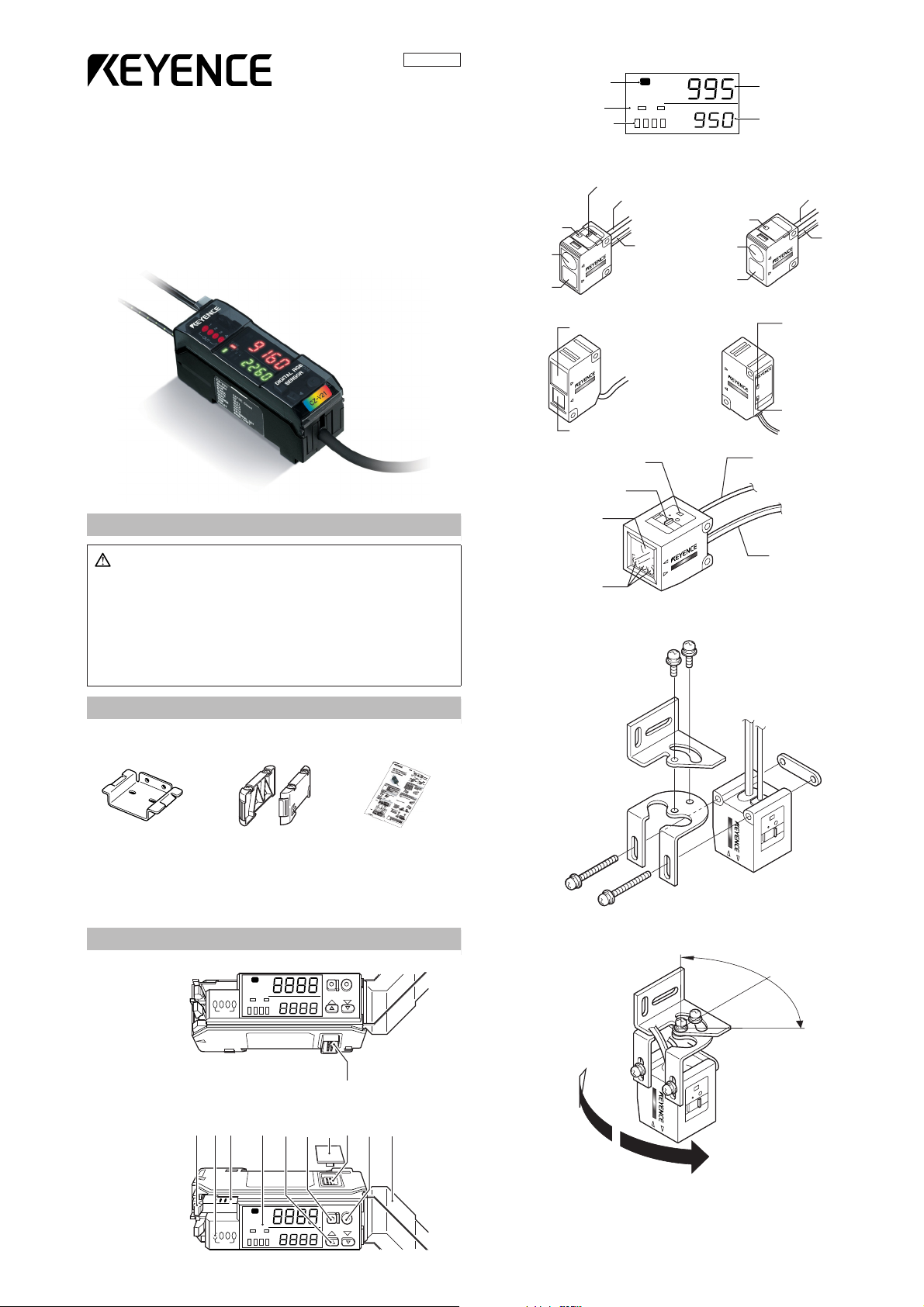
Color indicator*
(Lights at C/C+I mode)
Bank indicator
(At C/C+I mode)
Channel indicator
Current value monitor (red)
Setting value monitor (green)
C
Z
-
H
3
2
CZ-H35S
Detection
indicator
Emitter
Receiver
Spot selection switch
Light emission fiber
cable
Light reception
cable
Detection
indicator
Emitter
Receiver
Light emission
fiber cable
Light reception
cable
U
V
O
N
D
E
T
E
C
T
C
Z
-H
5
2
Receiver
Emitter
UV irradiation indicator
(green)
Detection indicator
(red)
Detection indicator
Spot selection switch
Emitter
Receiver
Light emission fiber cable
Light reception cable
■
■
■
■
■
96M1382
RGB Digital Fiberoptic Sensor
CZ-V21A(P)/V22A(P)
Instruction Manual
Display
* Film calibration indicator when using the CZ-H72
Sensor head
CZ-H32 CZ-H35S/H37S
CZ-H52
CZ-H72
BE SURE TO READ THESE MESSAGES CAREFULLY
Warning
• The CZ-V21(P)/V22(P) is just intended for the detection of target
objects. Do not use the CZ-V21(P)/V22(P) in a safety circuit to protect the human body.
• The CZ-V21(P)/V22(P) does not have an explosion-proof structure. Do not use it in a location where any flammable gases, liquid
or powder exist.
• The CZ-V21(P)/22(P) is a direct current type sensor. Application of
the AC power may lead to burst or fire.
• Do not directly look at the emitted LED beam.
• The CZ-H32/H35S/H37S/H72 are the Class 1 LED product in which
the light source LED is located in the amplifier unit.
• The CZ-H52 is the Class 1M LED product.
*When using the CZ-H52, be sure to read Precaution on Using CZ-
H52 on page 8.
ACCESSORIES
Amplifier unit
•Mounting bracket: 1 • End unit: 2 • Instruction manual: 1
Supplied with the CZ-V21A(P) Supplied with the CZ-V22A(P)
Sensor head
Common:
CZ-H32/H35S/H37 only : • M3 x 20 screw: 2
CZ-H52 only :
CZ-H72 only :
• Mounting bracket: 1 (two types, one of each for the CZ-H72)
• Board nut: 1
• M3 x 22 screw: 2
• Fiber insertion port cover seal: 1
• Ultraviolet ray spot check sheet : 1
• M3 x 30 screw: 2
• M3 x 6 screw: 2
PART NAMES
Amplifier unit
CZ-V22A(P)
1234
OUT
C
BANK
AB
1234
MODE
SET
Installing the supplied brackets on the CZ-H72
Install the two supplied brackets by combining them as shown below.
The sensor angle can be adjusted within 90° (± 45°).
(Refer to the lower right of page 9.)
Fixing lever
Output indicator
CZ-V21A(P)
E CZ-V21A(P)/V22A(P)-IM
1234
Display
Receiver connector
port
C
BANK
AB
1234
OUT
MODE button
Manual adjustment
button
MODE
Connection
connector
Connection
protection cover
SET
SET button
Dust cover
1
Page 2

■
MOUNTING THE AMPLIFIER UNIT
■ Mounting on a DIN rail
Hook the claw located on the bottom
of the amplifier unit to the DIN rail.
While pushing the amplifier unit in
the direction of the arrow 1, push it
down in the direction of the arrow 2.
To dismount the amplifier unit, while
pushing the main body in the direction of the arrow 1, raise the body in
the direction of the arrow 3.
3
2
1
■ Mounting on a bracket
Mount the amplifier unit using the
supplied mounting bracket as
shown in the figure.
CONNECTING SEVERAL AMPLIFIER UNITS
Up to three sub-units CZ-V22A(P) can be mounted adjacent to the main unit CZV21A(P). By connecting several units, the number of power cables can be
reduced.
1
Remove the protection cover on the side of the
amplifier.
2
Mount the sub-unit on the DIN rail.
MOUNTING THE SENSOR HEAD
4
3
2
B
1
K
N
A
A
T
B
U
Connector
port
Fiber cable port
Open the dust cover.
1
2
Tilt the fixing levers.
3
Insert the fiber cable and the connector of the sensor head into the corresponding ports.
Be sure to insert the fiber cable until it reaches the deepest end (the
inserted length: about 20 mm).
* The CZ-H52 is not supplied with the fiber cable.
Attach the supplied cover seal on the fiber cable insertion slot when
using the CZ-H52.
4
Lock them with the fixing levers.
5
Route the cable of the connector under the fixing lever.
When the cable of the sensor head is too long
Fabricate the cable end as shown in the figure.
1
C
O
4
3
2
1
2
1
3
Connect the sub unit to
the connector on the main
unit by sliding the sub unit
toward the main unit until a
clicking sound is heard.
Mount the end units on both
4
sides.
Fasten the screws on the top
of the end units (at two positions on both end units) with
the Philips screwdriver.
10 mm or more
Tilt the lid of the connector in the direction of the arrow indicated on its
2
left-hand side, and open the connector.
3
Insert the wires to the deepest end with the shielded wires bent upward.
Bend the shielded wires along the grooves in the direction of the arrows.
Be sure to match the colors of the sticker on the connector with those of
the shielded wires.
White
Close the connector to crimp down the wires, and tilt the top to lock.
4
Shielded wire
Red
Core
90°
Trim off the wires sticking out of the connector by using a nipper or the
5
like.
Note
2
Limit the reconnection to two times.
E CZ-V21A(P)/V22A(P)-IM
Page 3
■
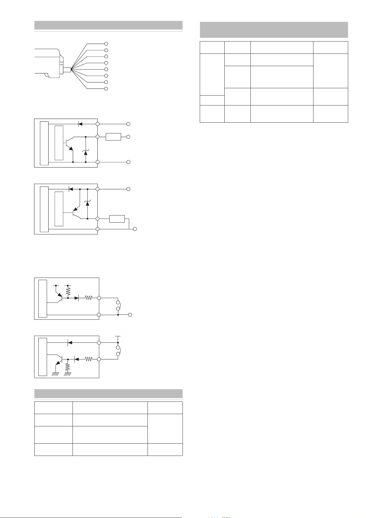
INPUT/OUTPUT CIRCUIT SCHIMATIC
Connection diagram
*
CZ-V21A and V21AP only
■ Output circuit
CZ-V21A • V22A *CZ-V21A only
Overcurrent protection
Sensor main circuit
CZ-V21AP • V22AP *CZ-V21AP only
*
Brown
Black
White
Gray
Orange
Pink
Purple
Blue
24 VDC
Output 1
Output 2
Output 3
Output 4
*
External calibration
External bank selection/external shift
*
0 V
Brown*
Black/white/gray/orange
Load
Blue*
Brown*
24 VDC
5 to 40 VDC
0 V
24 VDC
SENSOR HEAD MODES AND REFERENCE PAGES
FOR SENSITIVITY SETUP METHOD
Model Mode Description
Detects the target based on the
color components (R, G, B).
Detects the target based on the
color components (R, G, B) and
light intensity (amount of light
received).
Detects the target based on the
light intensity (amount of light
received).
Detects the target based on the
luster difference.
CZ- H32
/H35S
/H37S
CZ-H52
CZ-H72
C mode
C+I mode
Super I
mode
Luster
detection
mode
Sensitivity setup
method
Refer to page 4.
Refer to page 5.
Refer to page 6.
Black/white/gray/orange
Sensor main circuit
Overcurrent protection
Blue*
■ Input circuit
• External calibration (pink)
• External bank selection/external shift (purple)
CZ-V21A • V22A *CZ-V21A only
3.3 VDC
Pink*/purple
(Short-circuit current
1 mA max.)
Sensor main circuit
C
CZ-V21AP • V22AP *CZ-V21AP only
t 1
t 2
t 3
t 4
nal calibration
nal bank selection/external shift
Sensor main circuit
Blue*
Brown*
Pink*/purple
Load
0 V
PLC etc.
0 V
24 V
PLC etc.
DETECTION MODES
Mode Description
C mode
C+I mode
Super I mode
Detects the target based on the color
components (R,G,B).
Detects the target based on the color
components (R, G, B) and light intensity
(amount of light received).
Detects the target based on the lithgt
intensity (amount of light received).
* For the CZ-H52, the selectable detection mode is “Super I” mode only.
E CZ-V21A(P)/V22A(P)-IM
Sensitivity setup
method
Refer to page 3.
Refer to page 4.
3
Page 4

AB
MODE
BANK
1234
SET
■
■
■
■
■
■
OPERATION PROCEDURE FOR USING THE C/C+I MODE
Description of indication
Matching rate display Received light intensity/
Matching
rate
Setting
value
Selecting the displaying channel: While holding down the MODE button,
press the UP or DOWN button (refer to page 6).
Press MODE.
Matching rate
Displays the degree of correspondence between the target color calibrated
as a reference and the target color currently being detected.
Setting range: 0 to 999 (larger value for higher matching rate)
Setting value
Displays the threshold value that judges how much correspondence between
the color of the current target and the color of the target calibrated as a reference is considered as an identical color.
Received light intensity
Displays the amount of light currently received.
Power mode (response time)
Displays the power mode currently being selected.
power mode display
(response time)
Received light
intensity
Power mode
Setting a sensitivity
For selecting a calibration mode, refer to page 5.
1-point calibration (for detecting a single specified color)
Place a tar
tion of the beam spot emitted from the sensor. Then press the SET button once.
• The set value appears in green.
get of which color is to be used as a reference onto the focus posi-
Fine-adjusting a sensitivity
Fine-adjusting a sensitivity by changing the setting value
The larger the setting value, the stricter the detection becomes, and the
smaller the setting value, the rougher the detection becomes.
To change the setting value (displayed in green digits), press the UP or
DOWN button.
MODE
C
BANK
AB
1234
1234
OUT
Fine-adjusting by using a target
Fine-adjust the setting value by performing an adding or eleminating calibration.
Adding calibration (setting-value decreasing calibration)
Set the target to be judged as an identical color. While holding down the SET
button, press the DOWN button.
C
BANK
AB
1234
Eliminating calibration (setting-value increasing calibration)
Set the target not to be judged as an identical color. While holding down the
SET button, press the UP button.
OUT
1234
SET
MODE
SET
MODE
SET
1234
OUT
C
BANK
AB
1234
2-point calibration (for discriminating two colors)
1
Place a target of which color is to be used as a reference onto the focus
position of the beam spot emitted from the sensor. Then press the SET
button once.
"SET" appears in green on the setting value monitor.
MODE
C
BANK
AB
1234
Place a target of which color is to be discriminated. Then press the SET
2
OUT
1234
button once.
• The set value appears in green.
Note
If the sensitivity difference is insufficient, the setting value monitor shows
"- - - -" in green.
SET
MODE
SET
1234
OUT
C
BANK
AB
1234
Permitting uneven color
At a 1-point calibration or a pinpoint calibration, the sensor continues sampling while the SET button is held down.
• The sampled colors are set to be judged as an identical color.
MODE
SET
1234
OUT
C
BANK
AB
1234
Setting value
At the sensitivity setting, the sensor automatically determines the setting
value. The setting value can also be preset to a fixed value manually. In that
case, perform the following operation.
MODE
1234
OUT
C
BANK
AB
1234
Pinpoint calibration (1-point calibration with a stricter criterion)
Suitable for performing a stricter detection than 1-point calibration.
The setup method is the same as that for 1-point calibration.
• The setting value becomes larger than that of 1-point calibration even if the
same target is used for calibration.
SET
Press the UP and DOWN buttons at the same time for three seconds or more.
• "F" appears in green on the left-hand side of the setting value monitor.
The cancellation method is the same as the method of fixing the setting value.
With the “F” being on display, the setting value does not change from the
fixed value even if the sensitivity setting is performed.
4
E CZ-V21A(P)/V22A(P)-IM
Page 5

AB
MODE
BANK
1234
SET
C
OUT
1234
■
■
■
■
■
■
■
OPERATION PROCEDURE FOR USING THE SUPER I MODE
Description of indication
(CZ-H32/H35S/H37S)
Received light
intensity indication
Received
light
intensity
Setting
value
Received light intensity hold indication
Peak
intensity
Bottom
intensity
Selecting the displaying channel: While holding down the MODE button,
(CZ-H52 only)
Received light
intensity indication
Received
light
intensity
Setting
value
press the UP or DOWN button (refer to page 6).
Press MODE.
When EASY
is selected
Press
MODE.
Press
MODE.
Received light intensity/
lightsource indication
When FULL
is selected
Press MODE.Press MODE.
Received light
intensity hold indication
Received light
intensity
Selected light
source
r: red
G: green
b: blue
Peak
intensity
Bottom
intensity
Setting a sensitivity
2-point calibration (basic)
1
Place a target onto the focus position of the beam spot emitted from the
sensor. Then press the SET button once.
• "SET" appears in green on the setting value monitor.
Positioning calibration (when positioning a target)
1
Press the SET button without a target.
• "SET" appears in green on the setting value monitor.
2
Place a target on the desired position. Then press the SET button for three
seconds or more.
Check that "SET" flashes, and release the SET button.
3
Fine-adjusting a sensitivity
Fine-adjusting a sensitivity by changing the setting value
To change the setting value (displayed in green digits), press the UP or
DOWN button.
MODE
1234
OUT
C
BANK
AB
1234
Shift function
Forcibly synchronizes the received light intensity with the preset value.
• Regular shift inputs from a PLC or other device stabilizes the detection of
the target that has a little light intensity difference. (For external inputs from
a PLC or other devices, refer to page 6.)
• The shift function can be used when the shift function selection is set to ON
(refer to page 5).
Note
The updated value after a zero shift input is cleared when the power is
turned off.
SET
MODE
BANK
AB
1234
OUT
Press the SET button once without the target.
2
• The set value appears in green.
Note
If the sensitivity difference is insufficient, the setting value monitor shows
"- - - -" in green.
C
1234
Setting the maximum sensitivity (when maximizing the sensitivity)
Press the SET button and hold it for three seconds or more without the tar-
1
get.
Check that "SET" flashes, and release the SET button.
2
Full auto calibration (when a target is moving)
1
While holding down the SET button, pass the target through the optical
axis.
2
Check that "SET" flashes, and release the SET button.
SET
MODE
1234
OUT
C
BANK
AB
1234
SET
Selecting a light source
The sensor selects the optimum source of the RGB lights used for detection
automatically at sensitivity setting.
The light source can be selected for each channel.
Note
To select the light source manually, perform the following operations.
1
2
To return to the automatic light source selection, press the UP and DOWN
button at the same time for three seconds or more.
* The CZ-H52 does not have the light source selection function.
The light actually emitted appears pale regardless of the selected light
source.
Manually selecting the light source
At the display of the received light intensity/light source selection, press
the UP and DOWN button at the same time for three seconds or more.
"F" appears on the left-hand side of the setting value monitor.
Select a light source by pressing the UP or DOWN button.
MODE
C
BANK
AB
1234
• Once the light source is selected manually, the light source remains
fixed even if the sensitivity value is changed.
OUT
1234
SET
E CZ-V21A(P)/V22A(P)-IM
5
Page 6

OPERATION PROCEDURE FOR USING THE
LUSTER DETECTION MODE (CZ-H72)
■ Description of indication
Received light intensity indication
(The value is larger as the luster is stronger.)
Received
light
intensity
Set value
Selecting the displaying channel: While holding down the MODE button,
press the UP or DOWN button.
Received light intensity
Received light
peak intensity
Received light
bottom intensity
hold indication
■
Film calibration (for detecting the presence or absence of a film)
1 Place a target with a film onto the focus position of the beam spot emitted
from the sensor. Then press the SET button once.
MODE
SET
1234
OUT
C
BANK
AB
1234
2 Place a target without a film onto the focus position of the beam spot emit-
ted from the sensor. Then press the SET button once.
Setting a sensitivity
■ 2-point calibration (basic)
1 Place a lustrous portion of the target onto the focus position of the beam
spot emitted from the sensor. Then press the SET button once.
• "SET" appears in green on the setting value monitor.
MODE
SET
1234
OUT
C
BANK
AB
1234
2 Place a matte portion of the target onto the focus position of the beam
spot emitted from the sensor. Then press the SET button once.
• The set value appears in green.
MODE
SET
1234
OUT
C
BANK
AB
1234
Fine-adjusting a sensitivity
■ Fine-adjusting a sensitivity by changing the setting value
To change the setting value (displayed in green digits), press the UP or
DOWN button.
■ Base calibration
(maximum sensitivity that does not detect the matte portion)
Place a matte portion of the target onto the focus position of the beam spot
emitted from the sensor. Then press the SET button once.
• The set value appears in green.
MODE
SET
Matte
Lustrous
1234
OUT
C
BANK
AB
1234
6
E CZ-V21A(P)/V22A(P)-IM
Page 7

MENU SELECTION
Pressing the MODE button for three seconds or more displays the menu, from
which each mode can be configured.
To exit the menu during setting, press the MODE button again for three seconds or more.
C
BANK
AB
1234
Press MODE for three seconds or more
enu display
C
BANK
AB
1234
When using
the CZ-H52/H72
C
BANK
AB
1234
C
BANK
AB
1234
C
BANK
AB
1234
End of the basic
menu display
C
BANK
AB
1234
When timer
is selected
as OFF
Press MODE
When using the
CZ-H32/H35S/H37S
Press MODE
Press MODE
When the access mode is selected as FULL
Press MODE
C
BANK
AB
1234
Selecting an access mode
Select by pressing UP or DOWN.
• Displays the basic menu only.
• Displays all menus.
Selecting a function (detection mode)
Select by pressing UP or DOWN.
• C mode: Detects color based on
• C+I mode: Detects color based
• Super I mode: Detects color
Selecting a power mode (response time)
Select by pressing UP or DOWN.
• HIGH SPEED: 200µs
• FINE : 1ms
• TURBO: 4ms
• SUPER: 8ms
Selecting an output mode
(can be set for each channel)*
Select by pressing UP or DOWN.
• Turns on at light green
• Turns on at a color other
The display inside the parentheses is when the Super
I mode is selected or the CZ-H52/H72 is used.
Selecting a timer mode
(can be set for each bank)*
Select by pressing UP or DOWN.
• Time r OFF
• On-delay
• Off-delay
• One shot
When timer is
other than OFF
color components
on color components
and light intensity
on
light intensity
(Turns on when the light
enters)
than light green
(Turns on when the light
is shielded)
Setting the timer time
Set by pressing UP or
DOWN.
Press MODE
based
When the Super
I detection mode
is selected or the
CZ-H52 is used
When the C/C+I
detection mode is
selected or the
CZ-H72 is used
When the
shift function
is selected
as off
End of menu
display
C
BANK
AB
1234
C
BANK
AB
1234
C
BANK
AB
1234
C
BANK
AB
1234
C
BANK
AB
1234
Selecting the power saving function (Eco mode)
Select by pressing UP or DOWN.
• Normal use
• Enables the power saving function
Press MODE
When the C/C+I
detection mode is
selected or the
CZ-H72 is used
Press MODE
Press MODE
When the Super I detection
mode is selected or the
CZ-H52/H72 is used
Press MODE
C
BANK
AB
1234
Selecting calibration mode
Select by pressing UP or DOWN.
When the C/C+I mode is selected
• 1-point calibration
• 2-point calibration
• Pinpoint calibration
When the CZ-H72 is used
• 2-point calibration
• Base calibration
• Film calibration
Selecting the attenuation mode
Select by pressing UP or DOWN.
• Normal use
• Lowers the light receiving sensitivity
Selecting the shift function
Select by pressing UP or DOWN.
• Normal use
• Enables the shift function
When the shift
function is
selected as on
Press MODE
Setting the shift target value
Set the value by pressing UP
or DOWN.
* For the method of selection, refer to page 6.
E CZ-V21A(P)/V22A(P)-IM
7
Page 8

OTHER FUNCTIONS
■ Power saving function
If the Eco mode is turned on, three minutes’ absence of operation brings the
sensor to the power saving state. (For switching to the Eco mode, refer to
page 5.)
To r eturn the display to the normal state, press any one of the operation buttons.
■ Changing channels
The sensitivity can be set for each of the following number of channels
depending on the detection mode.
• C/C+I mode: 8 channels (4 channels x 2 banks)
• Super I mode: 4 channels (no bank selection)
* When using the CZ-H52/H72, the 4 channels can be used.
To select the display channel, perform the following operation.
While holding down the MODE button, press the UP or DOWN button.
MODE
SET
BANK
AB
1234
C/C+I mode
1 channels 2 channels 3 channels 4 channels
BANK
AB
1234
BANK
AB
1234
BANK
AB
1234
BANK
AB
1234
■ Externally inputting a shift input
(In the Super I mode setting/When using the CZ-H52/CZ-H72)
1 Connect the purple wire to the external devices such as a switch and a
PLC.
2 Short-circuiting the purple wire as shown below for each model enables
the shift input.
(The shift input is performed at the rising edge of the input signal.)
Brown
Blue
Purple
The minimum input time is 20 ms.
CZ-V21APCZ-V21A
Brown
Purple
Blue
■ Selecting a bank by the external input (in C/C+I mode)
1 Activate the keylock function.
2 Connect the purple wire to the external devices such as a switch and a
PLC.
3 Short-circuiting the purple wire as shown below for each model switches
the bank from A to B.
(The bank is set to B while the input signal is ON.)
Brown
Blue
Purple
The minimum input time is 20 ms.
CZ-V21APCZ-V21A
Brown
Purple
Blue
5 channels 6 channels 7 channels 8 channels
BANK
AB
1234
BANK
AB
1234
BANK
AB
1234
BANK
AB
1234
Super I mode
1 channels 2 channels 3 channels 4 channels
BANK
AB
1234
BANK
AB
1234
BANK
AB
1234
BANK
AB
1234
■ Keylock
Disables the key operation to change settings.
While holding down the MODE button, press the UP button for three seconds
or more.
The cancellation method is the same as that of locking.
■ Interference protection function
The CZ-V20A series can prevent mutual interference by connecting several
amplifier units.
Power mode HIGH SPEED FINE/TURBO/SUPER
Number of units
required to prevent
interference
Unavailable 2
* Total number of the main- and sub-units
EXTERNAL INPUT
■ Setting a sensitivity by the external input (external calibration)
1 Activate the keylock function.
2 Connect the pink wire to the external devices such as a switch and a PLC.
3 Short-circuiting the pink wire as shown below for each model equals the
operation of pressing the SET button.
Brown
Blue
Pink
The minimum input time is 20 ms.
The external calibration to the connected sub-units (CZ-V22A(P), FS-T2(P), or
PS-T2(P)) can be performed together with the main unit.
Lock only the sensor for which to perform external calibration. The setting
content is the same as that of the main unit.
CZ-V21PCZ-V21
Brown
Pink
Blue
DEFAULT MODE SETTINGS (INITIALIZATION)
Access mode EASY
Function (detection mode) C mode
Calibration mode 1-point calibration
Power mode (response time) TURBO
Output mode no (L-on)
Timer mode OFF (timer value 20 ms)
Power saving function (Eco mode) OFF
Attenuation OFF
Shift function OFF (shift value 0)
* When using the CZ-H52, the function (detection) mode and the calibration
mode are not displayed.
** When the CZ-H72 is used, the function (detection) mode is not displayed.
■ Resetting to the default settings
1 While holding down the MODE button, press the SET button five times.
• The monitor shows "rSt/no".
SET
MODE
BANK
AB
1234
2 Press the UP button.
• The monitor shows "rSt/YES".
SET
MODE
BANK
AB
1234
3 Press the MODE button.
• The sensor returns to the default state.
To cancel the reset operation, select “no” in step 2, and press the MODE button.
8
E CZ-V21A(P)/V22A(P)-IM
Page 9

SPECIFICATIONS
45°
■ Sensor head
(small
spot
ø1
IP40
45 g
Fluorescent
object
detection
CZ-H52 CZ-H72
)
At the
setting
distance of
25 mm:
ø10
(ultraviolet)
LED
(35 nm)
425 to 550
Approx. 40 g
UV
nm
Glass
Luster
detection
15-mm
center
At the
setting
distance
of
15 mm
Small:
approx. ø3
large:
approx. ø5
Red LED
(665nm)
–
Approx.
50 g
*2
*3
:
Type
Model CZ-H32
Detecting range
(mm)
Recommended
setting distance
(mm)
Minimum spot
diameter
Light source
Received light
wavelength
(at receiver)
Tolerated
bending radius of
fiber (mm)
Operating
ambient
temperature:
Operating
ambient
illumination
Protection
structure
Housing
Materi
Lens
als
cover
Weight
(including 2-m
cable)
Spot
selectable
50 to 95 28 to 52 11 to 20 25 to 55
70 40 15 35 15
Depending on
the reference
distance*
Small: ø3/
medium: ø4.5/
large: ø5.5
Polyarylate
Approx. 40 g
Canceling glaze
CZ-H37S
CZ-
H35S
Setting
distance
40 mm
ø4.5
Red LED (665nm)
Green LED (520nm)
Bule LED (465nm)
–
R25 R15 – R25
Incandescent lamp: 10000 rx or less
(Metal part: SUS304)
Setting
distance
16 mm
–10 to +55°C (No freezing)
Sunlight: 20000 rx or less
Glass reinforced resin
Tr iacetate
Polyarylate
Approx.
*1 Reference distance
Small: 65 mm, medium: 60 mm, large: 50 mm
*2 Large spot: 15 ± 5 mm, small spot: 15 ± 3 mm
*3 The focus distance is about 10 mm, but stable detection can be achieved
with 15 mm.
■ Amplifier unit
Model
Main/sub Main unit Sub-unit
Response speed
Control output*
External calibration input
External bank selection
input (C/C+I mode)
External shift input
(Super I mode)
Protection circuit
Power supply voltage
Current consumption
IEC Class (IEC 60825-1) Class 1 LED product
Operating ambient
temperature*
Vibration
Materials Housing material: Plycarbonate
Weight (including 2-m cable)
*1 20 mA maximum when several units are connected.
*2
NPN output CZ-V21A CZ-V22A
PNP output CZ-V21AP CZ-V22AP
200 µ s (HIGH SPEED)/1 ms (FINE)/4 ms (TURBO) /
8 ms (SUPER)
NPN (PNP) open collector x 4 CHs 40 VDC (30 VDC) max.
1
2
100 mA max. per output, 200 mA max. for the total of four
outputs
Residual voltage 1 V max.
No voltage input
Input response time 20 ms min.
Reverse-polarity protection, overcurrent protection, surge
absorber
24 VDC, Ripple (P-P): 10% max, Class 2
(the power-on reset time is 3 seconds.)
Normal mode: 1.5 W (62.5 mA max.)
Eco mode: 1 W (42 mA max.)
–10 to +55°C (No freezing)
10 to 55 Hz, 1.5 mm double amplitude in the X, Y, and Z
directions, 2 hours respectively
Approx. 110 g Approx. 100 g
When several units are connected, the acceptable ambient temperature var-
ies depending on the conditions given below. To connect several units, be
sure to mount them to a DIN rail. Ensure that the output current is 20 mA max.
When 1 to 2 units are connected: -10 to +50 °C
When 3 units are connected: -10 to +45 °C
MOUNTING THE SENSOR HEAD
■ Extraneous light
A detection error may occur when the light from high-frequency lighting equipment
such as an inverter fluorescent lamp directly enters or reflected on the target into
the emitter. In such a case, apply a light shield plate or change the location of the
sensor
.
Inverter fluorescent lamp, etc.
Light shield plate
■ Ta rget movement and sensor orientation
To stabilize the sensor output at a border, mount the sensor as shown in the
following figure as much as possible.
Movement direction
■ When using the CZ-H32
When detecting a metal surface or glossy target
When a target has a metal or glossy surface, the calibration/differentiation
may fail. To detect such a target, tilt the sensor head by approximately 10 to
15 degrees.
10° to 15°
■ When using the CZ-H35S/CZ-H37S/H72
When a target has a glossy surface (a birefringence target such as an oriented film), the detection may fail depending on the mounting orientation. To
detect such a target, displace the sensor head by approximately 45 degrees.
Movement direction
E CZ-V21A(P)/V22A(P)-IM
9
Page 10

ERROR INDICATION
The following indications on the LCD display show the error events.
Correct the problem using the following countermeasures.
Error
indication
nnnn
vvvv
Erk
Er[
Note
When an error indication not listed above is displayed, contact your nearest
KEYENCE office.
Cause Countermeasures
• Install the sensor within the specified
detecting distance.
Received light intensity
is insufficient.
Received light intensity
is excessive.
Sensor head is not
connected.
Head cable is broken.
Overcurrent flows
through the output
wire.
ON/OFF judgment is performed even with the “nnnn” of “ ” display.
• Check whether the fiber cable is inserted
into the sensor to its deepest end.
(approx. 20 mm)
• Delay the response time.
Tu rn on the attenuation mode.
• Tilt the sensor head by approx. 10 to 15
degrees.
• Check that the sensor head is
connected.
• Check that the head cable is not broken.
• After checking these points, turn on the
power again.
• Check the load and reduce the current to
be within the rated range.
• Check that the output wire does not
touch another wire or a frame.
vvvv
RECEIVED LIGHT INTENSITY INDICATION
In the received light intensity indication, the number larger than 9 at the top
digit is substituted with an alphabet.
Maximum value displayed: P599 Actual value: 25599
■ Denotation of indication
Indication
Alphabet
A
B
C
D
E
F
Number
10
11
12
13
14
15
Indication
Alphabet
I
J
K
L
M
N
Number
18
19
20
21
22
23
SAFTY PRECAUTIONS
• Isolate the sensor cable from the power line or the high voltage line.
The use of these lines in the same pipe generates noise, which may cause
malfunction.
• When a number of colors enter into the beam spot, they are averaged
down in recognition, resulting in the output of the color that is different from
the preset color.
•To extend the amplifier cable, use the cable with the nominal cross-sectional area no less than 0.3 mm
• When using the commercially available switching regulator,
be sure to earth the frame ground terminal and the ground terminal.
• Do not use the sensor outdoors.
• Even in the detection of the same color, the displayed value may vary due
to the reason such as amplifier’s individual characteristics, sensor head
cable length, and different mounting conditions.
2
, and with the length no more than 100 m.
WARRANTIES AND DISCLAIMERS
KEYENCE warrants its Products to be free from defects of material and workmanship and will, without charge, replace or repair (at KEYENCE’s sole
option) any Products found defective upon inspection at its factory, or other
designated point provided the equipment has been returned, transportation
prepaid, within one year from the date of shipment. Warranty is specifically at
the factory. Any on-site service will be provided at the sole expense of the
Purchaser at standard field service rates. All associated equipment must be
protected by properly rated electronic/electrical protection devices.
KEYENCE shall not be liable for any damage due to improper engineering,
installation, interfacing, use, modification or any action not in accordance with
this instruction manual. Proper installation, operation and maintenance of the
product in accordance with this instruction manual become the responsibility
of the user upon receipt of the Product. The user shall indemnify KEYENCE
and hold KEYENCE harmless from any liability or damage whatsoever arising
out of any action not in accordance with this instruction manual. Components
which wear are not warranted.
OTHER THAN AS STATED HEREIN, THE PRODUCTS ARE PROVIDED WITH
NO OTHER WARRANTIES WHATSOEVER.
ALL EXPRESS, IMPLIED, AND STATUTORY WARRANTIES, INCLUDING,
WITHOUT LIMITATION, THE WARRANTIES OF MERCHANTABILITY, FITNESS
FOR A PARTICULAR PURPOSE, AND NON-INFRINGEMENT OF PROPRIETARY RIGHTS, ARE EXPRESSLY DISCLAIMED. IN NO EVENT SHALL KEYENCE AND ITS AFFILIATED ENTITIES BE LIABLE TO ANY PERSON OR
ENTITY FOR ANY DIRECT, INDIRECT, INCIDENTAL, PUNITIVE, SPECIAL OR
CONSEQUENTIAL DAMAGES (INCLUDING, WITHOUT LIMITATION, ANY
DAMAGES RESULTING FROM LOSS OF USE, BUSINESS INTERRUPTION,
LOSS OF INFORMATION, LOSS OR INACCURACY OF DATA, LOSS OF
PROFITS, LOSS OF SAVINGS, THE COST OF PROCUREMENT OF SUBSTITUTED GOODS, SERVICES OR TECHNOLOGIES, OR FOR ANY MATTER
ARISING OUT OF OR IN CONNECTION WITH THE USE OR INABILITY TO
USE THE PRODUCTS, EVEN IF KEYENCE OR ONE OF ITS AFFILIATED ENTITIES WAS ADVISED OF A POSSIBLE THIRD PARTY’S CLAIM FOR DAMAGES
OR ANY OTHER CLAIM AGAINST THE PURCHASER. No representation or
warranty, express or implied, made by any sales representative, distributor, or
other agent or representative of KEYENCE which is not specifically set forth
herein shall be binding upon KEYENCE. In some jurisdictions, some of the
foregoing warranty disclaimers or damage limitations may not apply.
G
H
16
17
O
P
24
25
Precaution on Using the CZ-H52
This sensor uses an ultraviolet LED as the light emitting source and a light
receptor element that has the enhanced sensitivity in the visible region. The
sensor is designed to reliably and easily detect fluorescent marks (such as
hidden marks painted with fluorescent paint, or fluorescent marks painted
with fluorescent paint).
■ Caution
Class 1M LED
The LED emits powerful ultraviolet light while turned on, which can be very
dangerous to the unprotected human eye. Do not view directly with optical
instruments (such as a microscope or a telescope or a magnifiers).
Doing so may result in eye injury.
If there is a risk of reflected ultraviolet light entering the eye, wear protective
goggles and avoid all risks of direct exposure to the eye.
■ Precaution on Detection
Some fluorescent objects cannot be detected by this sensor even though they
may be visible to the human eye. Check the types of fluorescence before use.
For your information, fluorescent materials include those which emit fluorescent light, phosphorescent light, and light accumulated from light-accumulative materials.
KEYENCE CORPORATION
1-3-14, Higashi-Nakajima, Higashi-Yodogawa-ku,
Osaka, 533-8555, Japan
Phone: 81-6-6379-2211 Fax: 81-6-6379-2131
AFFILIATED COMPANIES
KEYENCE CORPORATION OF
AMERICA
Phone: 201-930-0100 Fax: 201-930-0099
KEYENCE DEUTSCHLAND GmbH
Phone: 06102-36 89-0 Fax: 06102-36 89-100
KEYENCE (UK) LIMITED
Phone: 01908-696900 Fax: 01908-696777
KEYENCE FRANCE S.A.
Phone: 01 56 37 78 00 Fax: 01 56 37 78 01
KEYENCE ITALIA S.p.A
Phone: 02-6688220 Fax: 02-66825099
KEYENCE SINGAPORE PTE LTD.
Phone: 6392-1011 Fax: 6392-5055
Specifications are subject to change without notice.
.
10
KEYENCE (MALAYSIA) SDN BHD
Phone: 03-2092-2211 Fax: 03-2092-2131
KEYENCE (THAILAND) CO., LTD.
Phone: 02-369-2777 Fax: 02-369-2775
KEYENCE TAIWAN CO., LTD.
Phone: 02-2718-8700 Fax: 02-2718-8711
KEYENCE (HONG KONG) CO.,LTD.
Phone: 3104-1010 Fax: 3104-1080
KEYENCE INTERNATIONAL
TRADING (SHANGHAI) CO.,LTD.
Phone: 021-68757500 Fax: 021-68757550
KOREA KEYENCE CO., LTD.
Phone: 02-563-1270 Fax: 02-563-1271
© KEYENCE CORPORATION, 2005
0076-3 96M1382
Printed in Japan
E CZ-V21A(P)/V22A(P)-IM
B0124
 Loading...