

Page 1
WARNING
96M0744
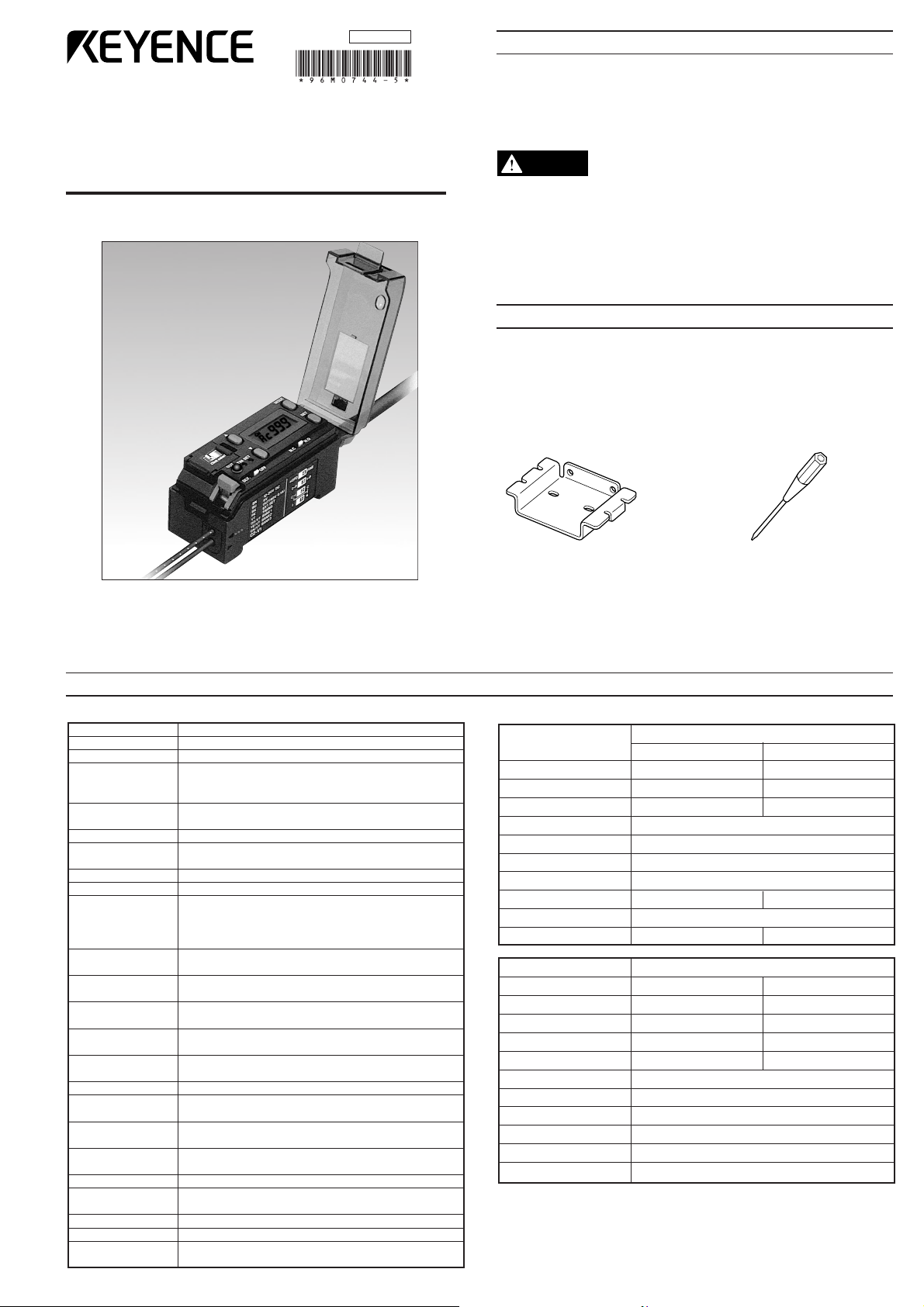
RGB Digital Fiberoptic Sensors
SAFETY PRECAUTIONS
This manual describes the instructions, operating procedures and
precautions for using the CZ Series.
Before beginning operation, please read this manual carefully to get the
most from your CZ Series.
Keep this manual handy for future reference.
CZ Series
Instruction Manual
• The CZ Series is intended for the detection of target objects. Do
not use the CZ Series in a safety circuit to protect the human
body.
• The CZ Series does not have an explosion-proof structure. Do
not use it in a location where any flammable gases, liquid or
powder exist.
ACCESSORIES
Instruction manual (This manual): 1
Mounting bracket: 1 Plastic screw driver: 1
SPECIFICATIONS
Amplifier Fiber unit
Model
Light source
Response time
Indicators
Error indication
Calibration method
Tolerance value
adjustment
Differentiation mode
Timer function
Output mode
selection
External synchronization input
External calibration
input
Registered color
selection
Control output
Protection circuit
Power supply
Current
consumption
Ambient light
Ambient
temperature
Relative humidity
Vibration
Shock
Housing material
Weight (including
2 m cable)
Red LED, Green LED, Blue LED
300 µs/1 ms (switch selectable)
Output: Red LED, Calibration: Orange LED,
External synchronization input: Green LED,
Matching rate/received light intensity: LCD (Red/Green)
Excess light intensity, insufficient light intensity,
C mode/C + I mode/I mode (switch selectable)
Timer OFF/OFF-delay timer (40 ms) (switch selectable)
Mismatch output: Turns on when target color is different
8-bank selection (By external input or key operation),
NPN open-collector: 40 VDC max. (100 mA max.),
overcurrent protection (output), surge protection (output)
1.
10 to 55 Hz, 1.5 mm double amplitude in X, Y, and Z
500 m/s
insufficient color difference
1-point/2-point calibration (switch selectable)
Numerical value setting on digital display
Match output: Turns on when target color
from registered color. (switch selectable)
Response speed: 500 µs max.
Input response time: 20 ms min.
Input response time: 20 ms min.
Residual voltage: 1.0 V max.
Reverse-polarity protection (power supply),
12 to 24 VDC±10%, Ripple (P-P): 10% max.
Incandescent lamp: 5,000 lux max.,
–10 to +55°C (14 to 131°F), No freezing
35 to 85%, No condensation
directions, 2 hours respectively
2
in X, Y, and Z directions, 3 times respectively
CZ-V1
matches registered color.
75 mA max.
Sunlight: 10,000 lux max.
Polycarbonate
Approx. 115 g
Type
Model
Detection range
Smallest spot diameter
Minimum bend radius
Enclosure rating
Ambient temperature
Relative humidity
Fiber length
Housing material
Weight
Detection method
Model
Type
Detection range
Smallest spot diameter
Minimum bend radius
Enclosure rating
Ambient temperature
Relative humidity
Fiber length
Housing material
Weight
1. When several units are connected, the acceptable ambient temperature varies
depending on the conditions given below. To connect several units, be sure to
mount them to a DIN rail (metallic plate). Ensure that the output current is 20
mA max.
• When 3 to 10 units are connected: -10 to +50°C (14 to 122°F)
• When 11 to 16 units are connected: -10 to +45°C (14 to 113°F)
Adjustable small beam spot
CZ-10
10 to 30 mm
0.9 to 3.5 mm dia.
–40 to +70°C (–40 to 158°F), No freezing
2 m (free-cut) 1 m (free-cut)
Lens housing: Aluminum, Fiber case: Stainless steel
Approx. 5 g Approx. 13 g
CZ-40
Long detecting distance
70±20 mm
6 mm dia.
R25 mm
–40 to +70°C (–40 to 158°F), No freezing
Reflective
Adjustable small beam spot, sideview
CZ-11
3 to 15 mm
0.9 to 1.5 mm dia.
R25 mm
IP40
35 to 85%, No condensation
Reflective
CZ-41
Small beam spot
16±4 mm
1 mm dia.
R15 mm
IP67
35 to 85%, No condensation
2 m (free-cut)
Polyarylate
Approx. 27 g
1
Page 2
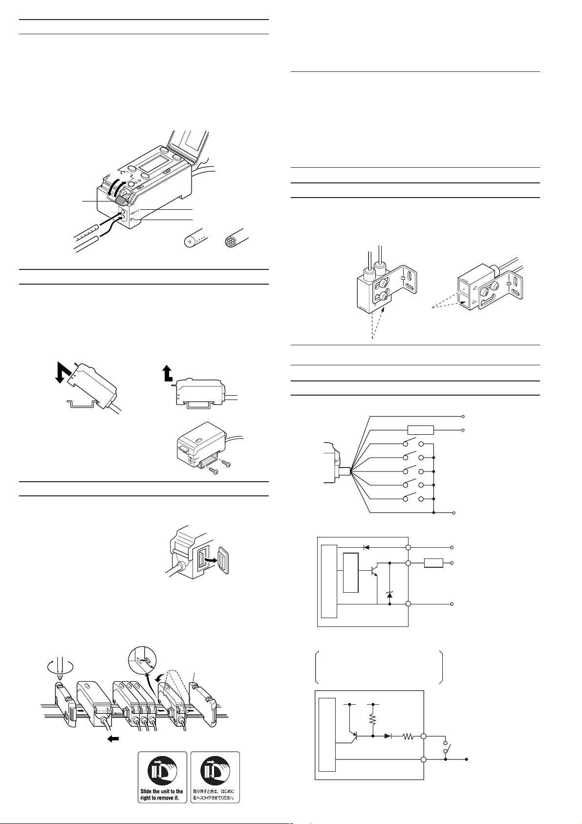
CONNECTING FIBER UNIT AND AMPLIFIER
1. Tilt the quick-release lever.
2. Push the single-core fiber to the transmitter side, and the multiplecore fiber to the receiver side as far as they will go (Approx. 14 mm of
the fiber will be inserted.).
* Inserting the fiber in the wrong side will decrease the original
detection performance. Be sure to check the markings on the
amplifier’s lateral side before inserting the fiber.
3. Raise the quick-release lever.
1
3
Quick-release lever
Single-core fiber
(with markings)
2
Multiple-core fiber
Single-core
(Transmitter side)
Transmitter side
(with markings)
Receiver side
Multiple-core
(Receiver side)
MOUNTING AMPLIFIER
■ Mounting/detaching amplifier to/from DIN rail or
mounting bracket
Hook the claw on the rear side of the amplifier onto the DIN rail or the
mounting bracket, and then hook the front side claw to the rail or
bracket while pressing the amplifier forward. To detach the amplifier,
unhook the front claw by lifting the amplifier front side while pressing it
forward.
Mounting
Detaching
■ DETACHING EXPANSION UNITS FROM DIN RAIL
1. Detach the end units.
2. Slide the expansion unit that is to be detached. Detach it individually
from the DIN rail.
Note 1: When connecting several amplifiers, be sure to use a DIN rail
and the end units.
Note 2: Be sure to turn the power off before connecting/disconnecting
amplifiers.
Note 3: Do not remove the protective cover on the expansion connector
from the outermost unit.
Note 4: Do not detach several units from the DIN rail while they are
connected to each other.
Note 5: When several units are connected, confirm that the ambient
temperature is appropriate. (See “Specifications” on page 1.)
MOUNTING FIBER UNIT
• Use the supplied special mounting bracket to mount the fiber unit in
the desired position according to the location.
• Be sure to limit the tightening torque to 0.3 Nm or less.
Mounting example 1 Mounting example 2
Reference: To cut the fiber to the desired length, use the special cutter
included with the fiber unit.
■ Side mounting
Using the side holes of the supplied
mounting bracket, secure the amplifier
with the screws.
CONNECTING SEVERAL AMPLIFIERS
■ Mounting expansion units
Up to 16 expansion units (FS-T2, FS-M2, FS-V12, PS-T2) can be
mounted to the side of the CZ-V1 amplifier.
1. Remove the protective cover on the
side of the amplifier.
2. Mount expansion units to the DIN rail
one at a time.
3. Slide one expansion unit toward the main unit or another unit. Align
the front claws of the units and push them together until you hear a
click.
4. Secure the units together by pushing the end units (included in the
expansion unit) from both sides.
Align the claw.
Main unit
Expansion
units
Up to 16 expansion units can be connected.
The sticker on the right is
included with the expansion
unit. Attach the sticker
close to the sensor units.
Remove the
protective cover.
End unit (included with
the expansion unit)
INPUT/OUTPUT CIRCUIT
Connections
Output circuit
Photoelectric sensor
main circuit
Input circuit
External calibration input
External synchronization input
External bank selection input 1 to 3
main circuit
Photoelectric sensor
Short-circuit current: Approx. 1 mA
Orange/purple
Overcurrent
protection
+5 V
Brown
Black
Pink
Purple
Yellow/purple
Green/purple
Blue
+5 V
100 mA max.
Load
External calibration
External synchronization
input
External bank selection 1
External bank selection 2
External bank selection 3
0 V
Brown
Black
Load
100 mA max.
Blue
12 to 24 VDC
5 to 40 VDC
0 V
Pink
Purple
Orange/purple
Yellow/purple
Green/purple
PLC, etc.
Blue
12 to 24 VDC
5 to 40 VDC
0 V
2
Page 3
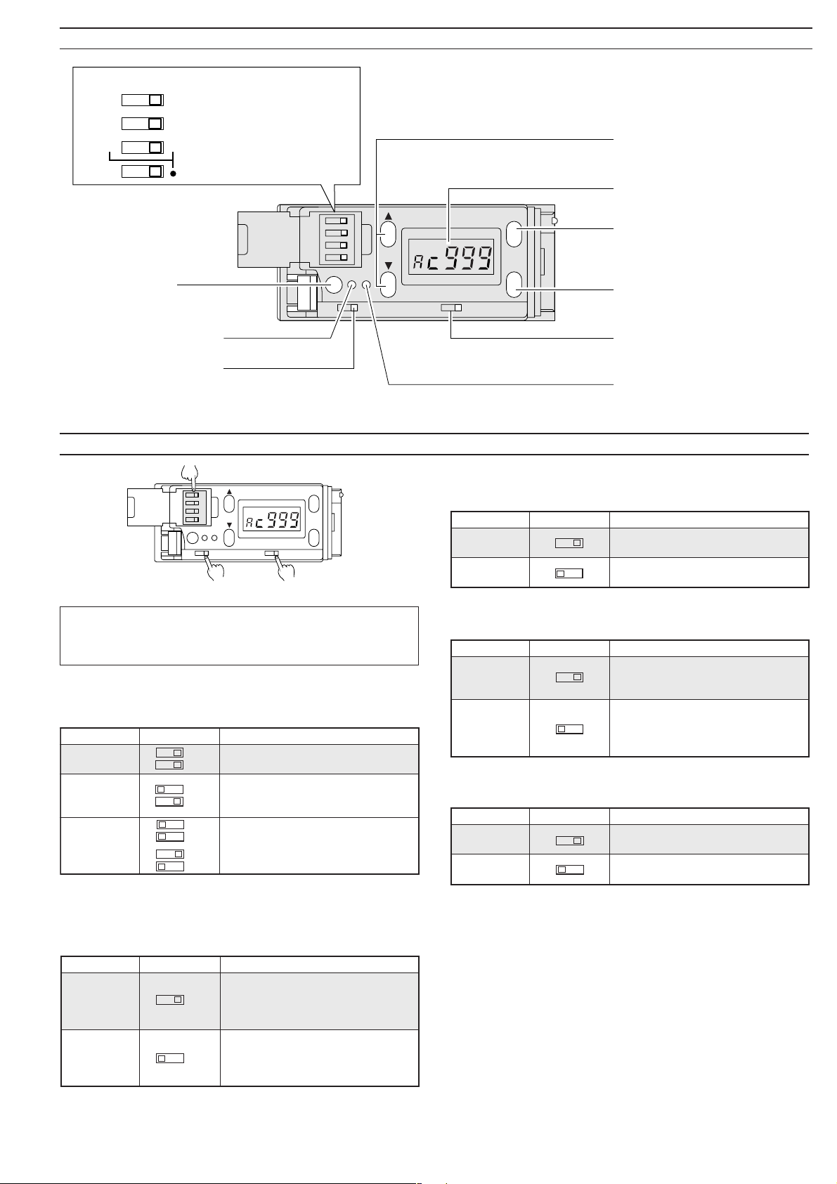
PART NAMES
DIP switches for mode setting
HSPD
2-P
C+I C
I
FINE
1-P
High-speed/High-precision
2-point/1-point calibration
Differentiation mode
selection
UP/DOWN key
• Changes sensitivity setting value.
• Changes channels.
LCD display monitor
1234
OUT
SET
DLY.
TIM
OFF
Output indicator
External synchronization
input indicator
Timer selection switch
Switches between Timer
OFF and 40 ms OFF-delay.
SETTING EACH MODE
DIP switch
MODE
SET
OFF
CH
N.C
SET
N.O
Output selection switch
.)Bdna,G,R(
thgildeviecerdna)Bdna,G,R(
1234
OUT
TIM
DLY.
Timer selection switch
Factory setting
“❋” indicates the factory-set mode. Normally, you should use the CZV1 with the setting indicated by “❋”, and only change the setting if
required.
■ Differentiation mode setting (Using DIP switches 1 and 2)
Change the setting according to the detection conditions such as the
target color or received light intensity.
edoMhctiwSnoitpircseD
❋
)roloC(C
I+C
dnaroloC(
)ytisnetni
I
or
)ytisnetnI(
Sensitivity setting in C or C + I mode ➞ Go to page 4.
Sensitivity setting in I mode ➞ Go to page 5.
2
1
2
1
2
1
2
1
MODE
MODE selection button
CH
SET
• Changes display.
• Shows matching rate.
• Shows setting value.
SET button
N.C
N.O
Sets sensitivity.
Output selection switch
Switches between N.O. and N.C.
Calibration indicator
■ FINE/HSPD selection (Using DIP switch 4)
Use HSPD when the detection requires a response speed less than 1
ms.
edoMhctiwSnoitpircseD
❋
ENIF
)niaF(
DPSH
)deeps-hgiH(
4
4
.noisicerp
003foesnopser µ .s
hgihhtiwsrolocsetaitnereffiD
deeps-hgihahtiwsrolocsetaitnereffiD
■ N.O./N.C. selection
Change the setting to invert the output mode.
edoMhctiwSnoitpircseD
.O.N
❋
N.C.
hctamroloC(
N.O.
)tuptuo
.C.N
roloC(
N.C.
hctamsim
stnenopmocrolocgnisurolocstceteD
stnenopmocrolocgnisurolocstceteD
■ Timer OFF/40 ms OFF-delay selection
)tuptuo
N.O.
.roloc
Change the setting to delay the output timing.
.)ytitnauqthgildeviecer(ytisnetni
thgildeviecergnisurolocstceteD
❋
.)ytitnauqthgildeviecer(ytisnetni
edoMhctiwSnoitpircseD
FFOremiT .yaledynatuohtiwnodenrutsituptuO
DLY.
sm04
DLY.
yaled-FFO
OFF
OFF
tegratehtnehwnodenrutsituptuO
.rolocderetsigerehtsehctamroloc
tegratehtnehwnodenrutsituptuO
deretsigerehthctamtonseodroloc
.sm04rofdeyaledsituptuO
■ 1-point/2-point calibration selection1. (Using DIP switch 3)
Change the calibration method.
edoMhctiwSnoitpircseD
❋
tniop-1(
)noitarbilac
3
).noitarbilac
P-2
P-1
tniop-2(
3
)noitarbilac
1. The setting of DIP switch 3 is effective only in the C and C + I modes.
The setting is unnecessary in I mode.
ehT(.rolocdeificepsenostceteD
tcetedottesyllacitamotuasiytivitisnes
gniruddetcelesrolocenoehtylno
.srolocdeificepsowtsetaitnereffiD
ottesyllacitamotuasiytivitisnesehT(
ehtetaitnereffidoteulavlamitpoeht
).noitarbilacgniruddetcelessrolocowt
3
Page 4

OPERATING PROCEDURE FOR USING C OR C + I MODE
CH
MODE
SET
N.O
N.C
OFF
SET
Press
Setting sensitivity
■ 1-point calibration (Detection of one specified color)
Place a target that is the reference color in the detection area of the
fiber unit. Press the SET button and then release it.
The calibration indicator illuminates momentarily and the reference
color is saved.
CH
OUT
TIM
SET
OFF
DLY.
N.C
Calibration indicator
● To ignore certain color differences
There are two methods for ignoring color differences.
• Perform the sensitivity adjustment after calibration. (➞ See the lower
right part of page 4.)
• Use the quick color difference cancellation function.
In 1-point calibration, hold down the SET button and continue the
calibration with targets of different colors. The CZ Series ignores the
color variation and saves them as the reference color.
CH
OUT
TIM
SET
OFF
DLY.
Calibration indicator
(Illuminates while the
SET button is held down.)
N.C
MODE
SET
N.O
Press this
button once.
MODE
SET
N.O
Hold down the
SET button.
● When calibration/differentiation fails
Check the following points.
• Check whether the fiber unit is mounted properly (detection
distance and detection angle). (See page 7.)
• Perform the sensitivity adjustment. (See below.)
• Select the other differentiation mode and then perform calibration
again. (See page 3.)
LCD display indication
Current value
(Matching rate display)
Channel
CH
Indicates the channel of
the amplifier currently
being monitored.
▲
Mode
“C” indicates that the current
mode is C or C + I. Nothing
appears while in I mode.
▲
CH
When “
nnnnnn
nnn” or “
nnnnnn
Setting value
The setting value
flashes on and off.
VVVVVV
VVV” is displayed
VVVVVV
These displays indicate that the received light is insufficient or
excessive. ➞ See page 7.
● Matching rate display
Displays the matching
degree (matching rate) of
the color of the currently
detected target to the
reference color registered
during calibration.
* Displays a value between 0
and 999. (Higher value
indicates a better match.)
MODE
Press the button once.
● Setting value display
Displays the threshold
value (criteria) of the
matching rate.
■ 2-point calibration (Differentiation of two colors)
1. Place a target that is the reference color in the detection area of the
fiber unit. Press the SET button and then release it.
The calibration indicator illuminates and the reference color is
saved.
MODE
CH
1234
OUT
TIM
SET
OFF
DLY.
N.C
Calibration indicator
2. Place a target that is the color to be differentiated in the detection
area. Press the SET button and then release it.
The calibration indicator goes off. The CZ Series sets the optimal
sensitivity to differentiate the two colors.
CH
OUT
TIM
SET
OFF
DLY.
Calibration indicator
N.C
SET
N.O
Press the
SET button
once.
MODE
SET
N.O
Press the
SET button
once.
Sensitivity adjustment
The tolerance of the detection can be adjusted.
1. Press the MODE button to show the setting value.
2. Press the UP/DOWN button to change the setting value.
CH
A higher value means
precise detection.
Narrow tolerance range
* After the adjustment, press the MODE button to return to the
matching rate display.
Press
A lower value means
Press
rough detection.
Wide tolerance range
CH
● When “- - -” is displayed:
When the sensitivity difference is insufficient for proper detection, the
LCD display monitor shows “- - -” for 3 seconds after calibration.
In this case, see “When calibration/differentiation fails” on the upper
right part of this page and try the calibration again.
4
Page 5

OPERATING PROCEDURE FOR USING I MODE
MODE
MODE
MODE
CH
CH
CH
Setting sensitivity
Select the sensitivity setting procedure according to the target conditions.
■ To set sensitivity using a moving target (Fully-automatic
calibration)
1. Pass a target through the optical
axis while pressing the SET
button (3 seconds or more).
2. Confirm that the calibration
indicator (orange LED) flashes.
3. Release the SET button. The
calibration indicator (orange
LED) goes off.
1234
OUT
TIM
SET
OFF
DLY.
Calibration
indicator
CH
N.C
Press the button
for 3 seconds or
more.
MODE
SET
N.O
LCD display indication
The display is factory-set to show the received light intensity.
Received light
intensity (4 digits)
Press this
button once.
Channel display:
Indicates the
channel of the
amplifier currently
being monitored.
Hold this button down
for 3 seconds or more.
Setting value (4 digits)
* The setting value flashes on and off.
Excess gain (%)
Press this button
once.
■ Excess gain display
Received light intensity is converted by
defining the setting value as 100P (%).
CH
■ To detect a minute color difference (2-point calibration)
1. With a target in place, press the
SET button and release it. The
calibration indicator (orange
LED) illuminates.
2. With the target removed, press
the SET button and release it.
The calibration indicator (orange
LED) goes off.
OUT
TIM
DLY.
Calibration
indicator
1234
SET
OFF
MODE
CH
N.C
SET
N.O
1. Press and release
the button with a
target in place.
2. Press and release
the button without
the target.
• Stable LIGHT status is obtained with 110P (%) or more.
• Stable DARK status is obtained with 90P (%) or less.
This display enables sensitivity adjustment using the UP/DOWN button.
■ Received light intensity display
Received light intensity is displayed in 4
digit numbers by defining the maximum
value as approximately 4000.
The maximum/minimum values vary depending on the fiber unit
characteristics.
CH
■ Setting value display
The current setting value is displayed.
This display enables sensitivity
■ For target positioning (Positioning calibration)
1. With no target, press the SET
button and release it.
The calibration indicator (orange
LED) illuminates.
2. Place a target in the position
where it is to be stopped.
3. Press the SET button for 3
seconds or more and confirm
that the calibration indicator
(orange LED) flashes.
OUT
TIM
DLY.
Calibration
indicator
1234
SET
OFF
CH
MODE
N.O
N.C
Press the button
and release it.
SET
adjustment using the UP/DOWN button.
Changing the setting value
You can change the setting value in the “Setting value display” and
“Excess gain display” modes.
In setting value display mode
MODE
increases the sensitivity.
SET
4. Release the SET button.
MODE
decreases the sensitivity.
SET
■ For stable detection unaffected by dust or dirt (Maximum
sensitivity setting)
1. Under the conditions shown in
the figure, press the SET button
for 3 seconds or more until the
calibration indicator (orange
LED) flashes.
With no target
OUT
TIM
DLY.
Calibration
indicator
1234
SET
OFF
CH
N.C
2. Release the SET button.
● When the sensitivity difference is insufficient:
“- - - - -” flashes for 3 seconds on the LCD display monitor after
calibration.
CH
MODE
SET
N.O
Press the button
for 3 seconds or
more.
In excess gain display mode
MODE
increases the sensitivity.
SET
MODE
decreases the sensitivity.
SET
Reference: Holding down the UP/DOWN button quickly changes
displayed values.
5
CH
(The setting value is
decreased.)
(The setting value is
increased.)
(The excess gain is
increased.)
(The excess gain is
decreased.)
Page 6

OTHER FUNCTIONS (COMMON TO C, C + I, AND I MODES)
+V
0V
Brown
Blue
Orange/purple
Yellow/purple
Green/purple
ON
OFF
ON
OFF
Locking the sensitivity setting
Hold down the MODE button and press the UP button for 3 seconds.
This locks the operation buttons.
•“Loc” flashes on and off on the LCD display monitor.
• You can still change the display mode and channel when in setting
locked status.
MODE
CH
DRY.
OUT
1234
TIM
SET
OFF
2
N.C
SET
➞
1
N.O
● To cancel the locked status
Repeat the procedure above while in
setting locked status. “UnL” flashes on and
off on the LCD display monitor.
Setting sensitivity using an external input
(External calibration function)
1. Lock the sensitivity setting using the
procedure above. (If “UnL” is displayed,
repeat the same procedure.)
2. Connect the pink cable to a switch or a PLC.
The minimum input time is 20 ms.
NPN
Brown
Blue
3. The external calibration procedure is the same as using the SET
Pink
+V
0 V
button. (➞ All the setting procedures on pages 4 and 5 are available
with the external input.)
Selecting CH display
The CZ-V1 can internally store 8 colors (banks). The banks can be
selected using the buttons or an external input.
● Selecting registered colors (banks) using an external input
The external bank selection cable allows the selection of 8 registered
colors from A through H.
knaB
A XXX
B
C X
D
E XX
F
G X
H
Controlling expansion units (FS-T2, FS-V12, PS-T2)
1. When “CH” is displayed, hold down the MODE button and momentarily press the UP/DOWN button. You can change the channel of the
amplifier being controlled. Select the channel of the desired expansion unit.
• The number of channels varies depending on the connected
expansion units. Up to 16 expansion units can be connected.
• The channel number starts at 2, which is the number of the expansion unit next to the main unit, and it increases to 3 through to 17.
CH
Channel
/egnarO
rolocelbaC
elprup
●
●●
●
●●●
/wolleY
elprup
XX
●
X
●●
/neerG
elprup
X
X
●
●
●:
X:
MODE
+
Main unit Expansion unit
MODE
+
CH2 CH3 CH4 CH17
● Selecting registered colors (banks) using the buttons
1. Hold down the MODE button*
and press the DOWN button for 3
seconds.
“CH” appears and flashes on the
LCD display.
2. Hold down the MODE button*
DRY.
OUT
TIM
1234
SET
OFF
CH
N.C
2
and momentarily press the UP/
DOWN button. The banks are
changed each time the UP/
DOWN button is pressed.
There are 8 banks from A
through H.
MODE
+
MODE
+
DRY.
OUT
TIM
1234
SET
OFF
CH
N.C
2
3. To finish the selection, hold down the MODE button and press the
DOWN button for 3 seconds.
“CH” stops flashing and remains illuminated.
MODE
CH
1234
OUT
TIM
SET
OFF
DRY.
* Be sure to hold down the MODE button first when operating the
MODE and UP/DOWN buttons.
N.C
2
SET
1
N.O
➞
CH
MODE
SET
Channel number
indication
CH
1
N.O
MODE
1-line expansion units
2. You can use the CZ-V1 to operate the selected expansion unit, for
SET
1
N.O
example to change the monitor display or sensitivity setting.
* The red and green color of the LCD display represents the ON/OFF
condition of the selected expansion unit.
Note 1: The FS-M2 cannot be controlled using the CZ-V1.
Note 2: When the channel of the FS-M2 is selected, “- - - -” appears on
the LCD display. (The red or green color of the LCD display represents
the ON/OFF condition of the FS-M2.)
External synchronization function
When the external synchronization input cable (purple) receives a
signal (connected to 0 V), the control output retains the condition at that
exact moment.
Detection
condition
External
synchronization
input
Control output
6
Match
Mismatch
This output
condition is
retained.
This output condition
is retained.
Page 7

HINTS ON CORRECT USE
Mounting amplifier
• If the amplifier cable is placed together with power lines or high
voltage lines in the same conduit, detection errors may occur due to
noise interference. Isolate the amplifier cable from these lines.
• If there are several colors in a single beam spot, the CZ-V1 determines the color by averaging those colors. Therefore, it may produce
an output even though the color is different from the registered color.
• To extend the cable length, use a cable with at least a 0.3 mm
nominal cross-section area. Limit the length of cable extension to
100 m or less. (To connect several units, contact Keyence for further
information.)
• When using a commercially available switching regulator, ground the
frame ground terminal and ground terminal.
• Do not use the CZ-V1 outdoors.
• Even when the same color is detected, the displayed value may vary
depending on the characteristics of each amplifier, the length of the
fiber cable and the location.
• When any of the external inputs (calibration, synchronization or bank
selection) are not used, cut the appropriate input cables (pink, purple,
orange/purple, yellow/purple or green/purple) at the root or connect
them to the “+” terminal of the power supply.
2
• Target movement and fiber unit orientation
To stabilize the sensor output at a border, mount the fiber unit parallel to
the border line as much as possible.
Incorrect
Target movement
direction
Correct
Target movement
direction
Fiber unit
• Prevent any objects from bumping the sensing surface.
• Do not pull the fiber cable of the CZ-40 and 41 using a strength of
greater than 20 N, 3 seconds.
Mounting fiber unit
•A detection error may occur when the target is subjected to direct or
reflected light from high-frequency lighting equipment such as an
inverter fluorescent lamp. In such a case, apply a light shield plate or
change the location of the fiber unit.
Inverter fluorescent lamp, etc.
Light shield
plate
• When detecting a metal surface or glossy target
When a target has a metal or glossy surface, the calibration/differentiation may fail. To detect such a target, tilt the fiber unit by approximately
10 to 15 degrees.
10° to 15°
ERROR INDICATIONS
The following indications on the LCD display show the error events.
rorrE
noitacidni
nnn
vvv
----
esuaCserusaemretnuoC
thgildevieceR
siytisnetni
.tneiciffusni
thgildevieceR
siytisnetni
.evissecxe
ni(ecnereffidroloC
➞ /noitarbilacnehW“eeS
ecnereffid“,edomI
si)”ytisnetnithgilni
otllamsoot
srolocetaitnereffid
tniop-2gnirud
.noitarbilac
sitinurebifehtrehtehwkcehC
.)mm41
(.seerged ➞ ”tinurebifgnitnuoM“eeS
).egapsihtfotraptfelehtno
.tnemtsujdaytivitisnesehtyrter
gnitceteddeificepsehttadellatsni
ehtotnielbacrebifehttresnI.ecnatsid
.xorppa(oglliwtisarafsatinurebif
51ot01.xorppaybtinurebifehttliT
dna4egapno”sliafnoitaitnereffid
7
Page 8

Correct the problem using the following countermeasures.
DIMENSIONS
CZ-V1
When mounted to DIN rail
Brown, blue: 0.45 mm
Black, Pink, Purple, Orange/purple,
ø5.2 x
green/purple, yellow/purple:
0.25 mm
Cable length: 2 m
2
2
When mounting bracket is attached
1.1
When the cover is opened: 78max
6.7
10.7
6.5
CZ-10
M6 P=0.75 mounting part
A
A
10 9.6
L 2000
L: lens unit length *adjustable part 4.2 to 9.3
5.2
A-A
cross
section
view
ø5.5
lens
2.6
ø6
CZ-40
5.8
6.3
13.2
25.5
13.2
24
5.8
36.5
16
5
11.6
1518.5
24 min.
2-ø3.2
8
Amplifier mounting bracket (accessory)
2 - (4.4 x 3.4)
8.4
3
*
11.514
28
35.4
53.5
Slot (Note)
ø3.3
(Mounting hole)
2-ø1.3
24 min.
transmitter
ø2.2 x 2
200033
(12.7)
CZ-11
2-ø3.2
45.0°
8.7
CZ-41
5.8
6.3
15.0
13.2
10.4
5.5
12.0
lens ø3.7
28.4
5.0
L
2.1
2.4
5.6
27
22
15
28.5
ø4.5 stainless steel
ø3.5 stainless steel
5.4
13.2
300
M3, P=0.5
Lens housing: Black anodized aluminum
L: 2.6 to 5.0
17.5 11.5
32
37 2000
SPCC
ø4.5 stainless steel
5.0
1000
2 - ø3.3
(Mounting hole)
ø2.2 x 2
0.5 11.5
(Note) Detail of slot
Fiber unit mounting bracket
(accessory)
33
t = 1.2
6
3.5
Stainless steel
2 x M3 screw
17.5
11.5
t = 1.5
9.5
11.5
18.7
Detail of slot
3.5
5
14.5
4
Stainless steel
3.6
8
11.518
3.6
WARRANTIES (MUST ACCOMPANY THE PRODUCTS): KEYENCE,
When mounting bracket is
attached to CZ-40
45
(32)
The fiber unit angle can be changed
by a maximum of 45 degrees upward
and downward.
at its sole option, will
refund, repair or replace at no charge any defective Products within 1year from the date of shipment. Unless
stated otherwise herein, the Products should not be used internally in humans, for human transportation, as
safety devices or fail-safe systems.
EXCEPT FOR THE FOREGOING, ALL EXPRESS, IMPLIED
AND STATUTORY WARRANTIES, INCLUDING WARRANTIES OF MERCHANTABILITY,
FITNESS FOR A PARTICULAR PURPOSE AND NON-INFRINGEMENT OF PROPRIETARY
RIGHTS, ARE EXPRESSLY DISCLAIMED. KEYENCE SHALL NOT BE LIABLE FOR ANY
DIRECT, INDIRECT, INCIDENTAL, CONSEQUENTIAL OR OTHER DAMAGES, EVEN IF
DAMAGES RESULT FROM THE USE OF THE PRODUCTS IN ACCORDANCE WITH ANY
SUGGESTIONS OR INFORMATION PROVIDED BY KEYENCE. In some jurisdictions, some of the
foregoing warranty disclaimers or damage limitations may not apply.
Copyright (c) 2002 KEYENCE CORPORATION. All rights reserved.
0744E 0059-5 96M0744 Printed in Japan
8
 Loading...