

Page 1
High-speed, High-capacity Machine Vision System
CV-X Series
Easy Setup Guide
369GB
Control/Communication I/O
(for all models)
Page 2

Contents
Easy Setup Guide: Control/Communication I/O (for all PLC models)
3
1. Outputting the Total Status
10
14
2. Outputting the individual status of each tool (parallel I/O)
3. Terminal command control
19
4. I/O terminal control (PW: Change Programs)
5. I/O terminal control (EXW: Write execute condition)
20
21
6. I/O terminal control (SS: Save Settings)
7. I/O terminal control (BS: Register Image)
22
Page
Page
Page
Page
Page
Page
Page
KEYENCE CORPORATION. Vision System Division
‐ 2 ‐ www.keyence.com
Page 3
Outputting the Total Status
1. Wiring
Perform the following wiring to output the total status of inspections.
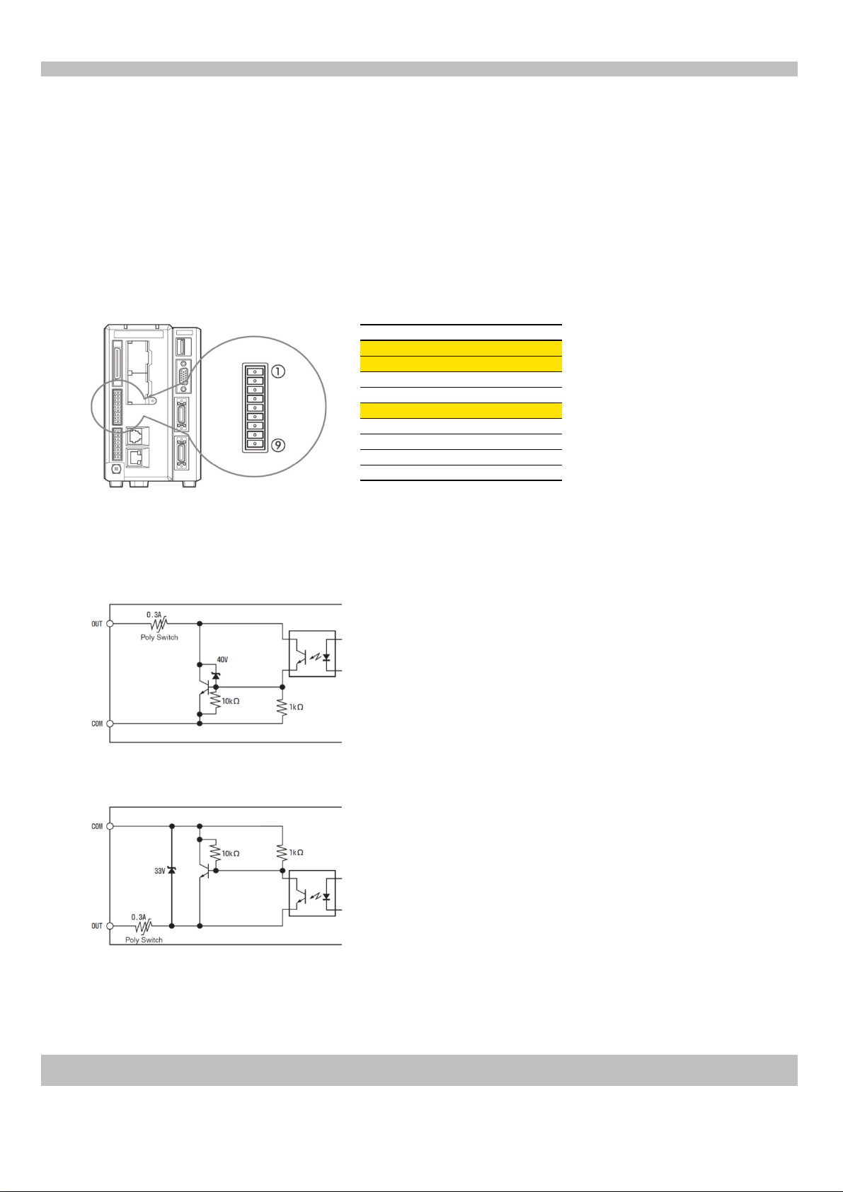
This section explains how to wire the terminal block "OUT22:STO" "OUT23:OR" to a PLC or relay.
(The terminal block is attached to the main unit)
Controller terminal block (OUT connector)
No.
1
2
3
4
Terminal name *1
OUT22 (STO)
OUT23 (OR)
F_OUT2 (ERR)
F_OUT3 (RUN)
COMOUT1 (COMOUT)5
F_OUT0 (FLS1)6
78F_OUT1 (FLS2)
COMOUT_F+ (COM1F+)
COMOUT_F‐ (COM1F‐)9
Suitable wire: AWG 16 to 28 Terminal block screw torque: 0.25 Nm or less
*1 The characters in brackets in the terminal name are the characters written on the supplied terminal blocks when shipped.
Output circuit diagram (NPN output type)
• Maximum applied voltage: 30 V
(No. 1, 2)
(No. 5)
• Maximum sink current: 50 mA
• Leakage current: 0.1 mA or less
• Residual voltage:
1.4 V or less (50 mA)
1.0 V or less (20 mA)
Output circuit diagram (PNP output type, controllers with a "P" at the end of the part number)
• Maximum applied voltage: 30 V
(No. 5)
(No. 1, 2)
KEYENCE CORPORATION. Vision System Division
• Maximum sink current: 50 mA
• Leakage current: 0.1 mA or less
• Residual voltage:
1.4 V or less (50 mA)
1.0 V or less (20 mA)
‐ 3 ‐ www.keyence.com
369GB
Page 4
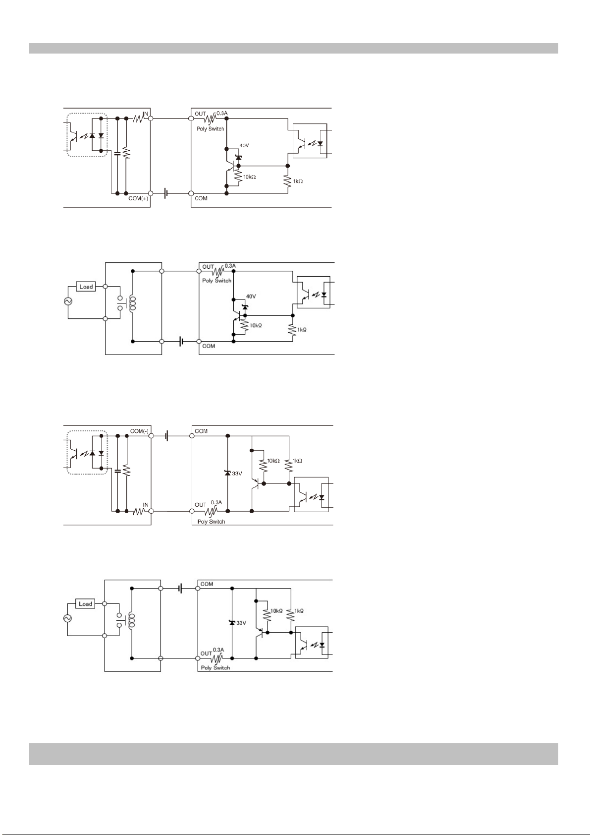
Example of connections (NPN output)
When connecting an NPN output from the controller to a PLC with a positive common
PLC input circuit positive common
Output circuit on controller
When connecting an NPN output from the controller to a relay
Output circuit on controller Relay
Example of connections (PNP output type, controllers with a "P" at the end of the part number)
When connecting a PNP output from the controller to a PLC with a negative common
PLC input circuit negative common
When connecting a PNP output from the controller to a relay
KEYENCE CORPORATION. Vision System Division
Output circuit on controller
Output circuit on controller Relay
‐ 4 ‐ www.keyence.com
Page 5
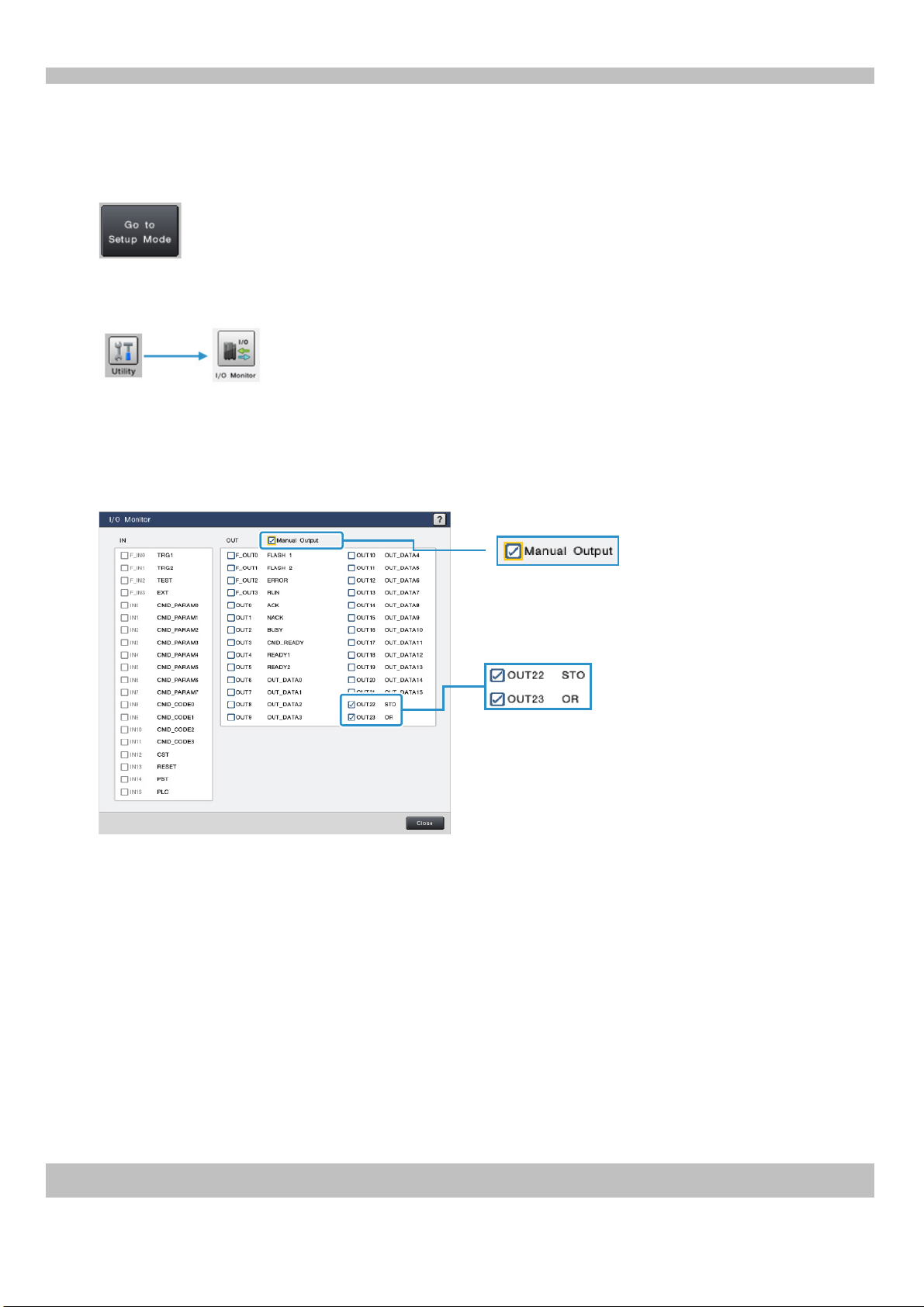
2. Checking the connection status of the external terminal (I/O Monitor)
The wiring connection of the external terminal of the CV‐X100 Series can be checked.
Cl
ick the button at the top right of the screen to switch to Setup Mode.
Select "Utility" > "I/O Monitor" to open the I/O Monitor.
Check the "Manual Output" box to forcefully turn selected output terminals ON, in order to confirm the signal on
the target.
Check the "OUT22 (STO)" and "OUT23 (OR)" boxes, and confirm that the ON/OFF status of the signal can be
detected on the target (PLC, relay, etc.). Check the box to set to ON (short circuit), and uncheck it to set to OFF
(open).
Manual Output can only be used in Setup Mode.
Check the box to set to ON (short circuit), and
uncheck it to set to OFF (open).
If proper ON/OFF status in conjunction with checking/unchecking the box cannot be confirmed, check the wiring
again.
KEYENCE CORPORATION. Vision System Division
‐ 5 ‐ www.keyence.com
Page 6
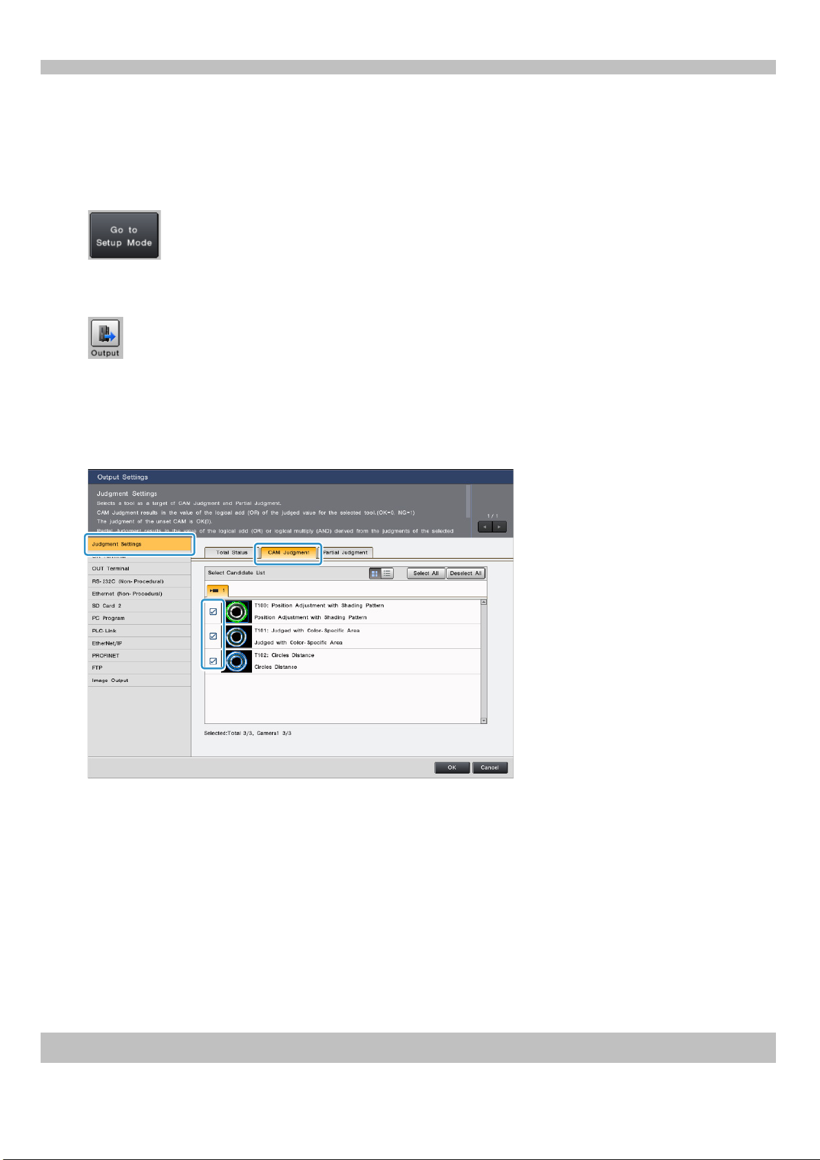
3. Setting the tools to be included in total status
Tools to include in the Total Status can be selected. This is useful when you wish to perform an overall judgment
using only the judgment results of specified tools.
Click the button at the top right of the screen to switch to Setup Mode.
Click "Output".
Select "Judgment Settings" > "CAM Judgment".
In the "Select Candidate List", confirm that the boxes for the tools to be included in total status are checked (when using
multiple cameras, confirm the settings for each camera tab).
KEYENCE CORPORATION. Vision System Division
www.keyence.com‐ 6 ‐
Page 7
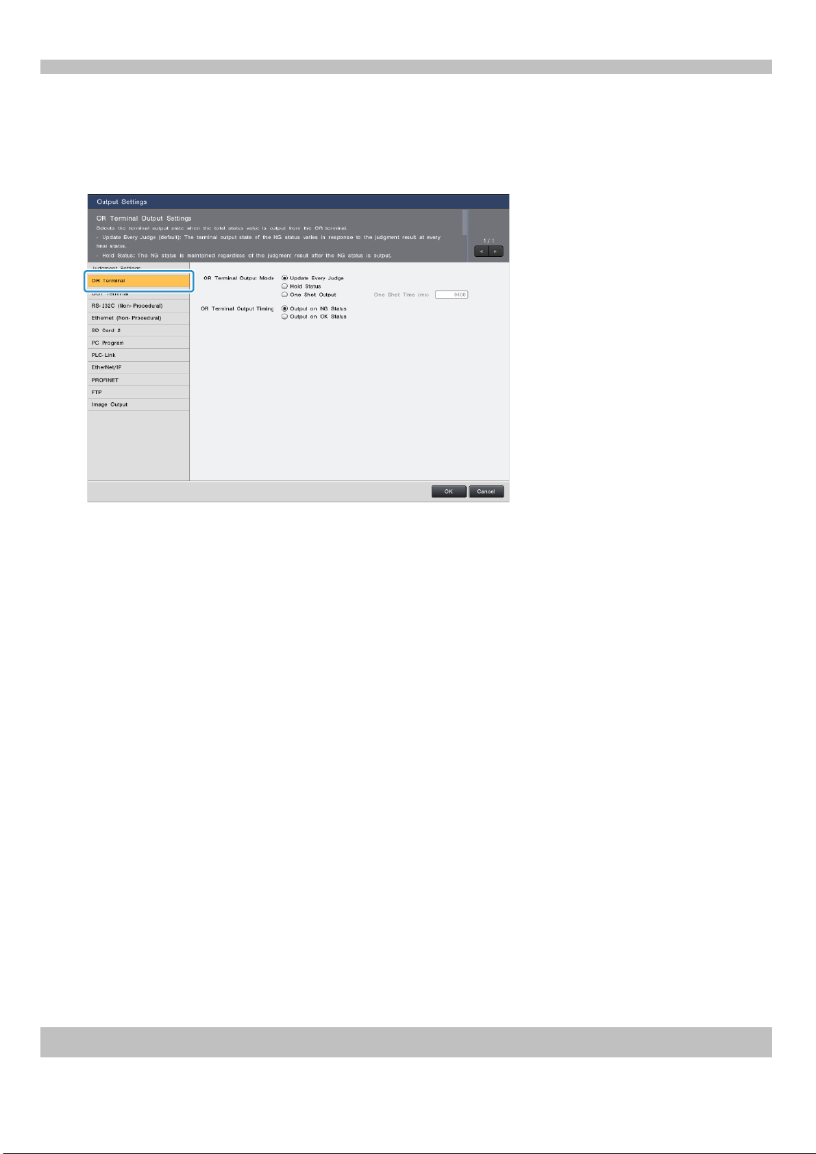
4. Setting the OR Terminal Output Mode
Select the terminal output mode for outputting Total Status from the OR Terminal.
Select "OR Terminal", and then set the "OR Terminal Output Mode" and "OR Terminal Output Timing".
OR Terminal Output Mode
•Update Every Judge: The terminal output state of the OR terminal is updated every time judgment is performed,
and is in accordance to the judgment result. It is synchronized with the leading edge of STO that is output every
time a judgment is finalized, and reads.
•Hold Status: When an NG Status is output, the NG status is retained, regardless of further judgment results.
•One Shot Output: The OR terminal turns on for the amount of time specified in "One Shot Time" and then turns
off.
OR Terminal Output Timing
•Output on NG Status
•Output on OK Status
Refer to the timing charts for each output mode on the following pages.
KEYENCE CORPORATION. Vision System Division
‐ 7 ‐ www.keyence.com
Page 8
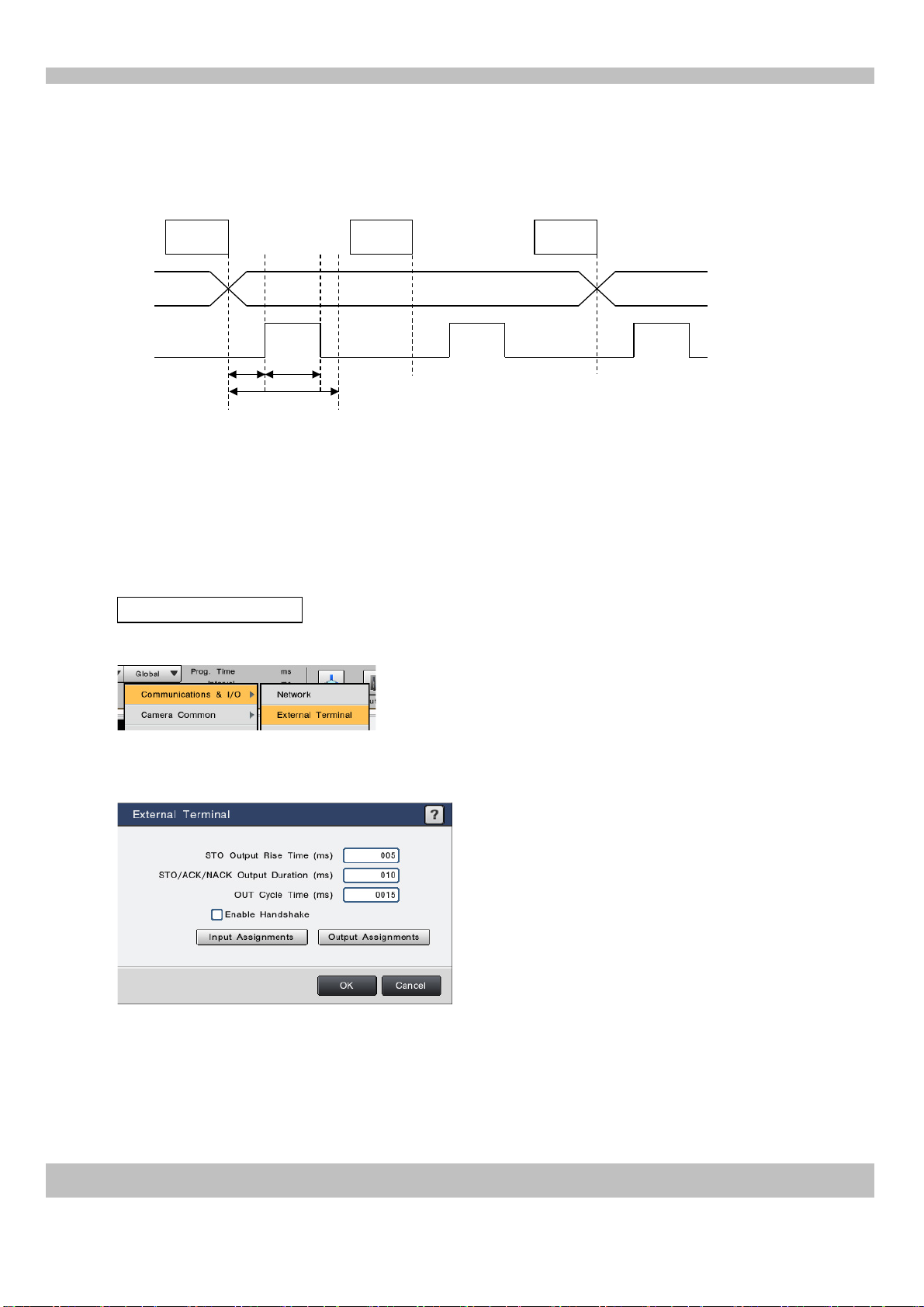
5. Timing Charts
This section includes a time chart for each OR Terminal Output Mode
•Update Every Judge
Image processing
NG Status
Image processing
NG Status
Image processing
OK Status
OR
STO
A B
C
When judgment is finalized, STO (OUT22) rises and the ON/OFF status of OR (OUT23) is checked simultaneously.
Adjust the output time for STO (A/B/C in the time chart) in global settings so that there is time for the target PLC to
detect the status.
A: Output rise time (1 to 999 ms)
B: Output time (1 to 999 ms)
C: Output change time (2 to 1000 ms)
However, ensure that "A + B ≦ C".
Changing the STO output time
Select "Global" > "Communications & I/O" > "External Terminal".
Adjust A: Output rise time (1 to 999 ms), B: Output time (1 to 999 ms) and C: Output change time (2 to 1000 ms) so
that there is time for the target PLC to detect the status. However, ensure that "A + B ≦ C".
KEYENCE CORPORATION. Vision System Division
‐ 8 ‐ www.keyence.com
Page 9

•Hold Status
Image processing
NG Status
Image processing
OK Status
Image processing
NG Status
Image processing
NG Status
OR
TEST
A A: TEST minimum input time (1 ms or more)
The status condition is normally updated for each trigger. However, if the status is NG, the condition is unchanged
until input such as TEST is executed.
If one NG is detected, the OR output status remains NG from that point, regardless of the actual judgment results.
When the TEST input is turned on/off, the hold status is canceled and all terminals are reset to the normal state. The
OR output condition will be updated when the result for the next OR output is output.
•One Shot Output
Image processing
NG Status
Image processing
NG Status
Image processing
OK Status
OR
A: One shot time (1 to 9999 ms) A
The OR output holds the NG state for the specified period of time, and then resets the NG state.
If image processing is continuously performed with One Shot Output enabled, the previous NG state may still be
remaining at the time the image processing judgment result is finalized by the STO.
KEYENCE CORPORATION. Vision System Division
‐ 9 ‐ www.keyence.com
Page 10

39
OUT21 (OUT_DATA15)
White
40
COMOUT2
Black
37
OUT19 (OUT_DATA13)
Purple
29
↓
36
OUT18 (OUT_DATA12)
Blue
Blue38OUT20 (OUT_DATA14)
Gray
27
OUT9 (OUT_DATA3)
Purple
28
OUT10 (OUT_DATA4)
Gray
24
OUT6 (OUT_DATA0)
Yellow
OUT11 (OUT_DATA5)
White
30
OUT12 (OUT_DATA6)
Black
26
OUT8 (OUT_DATA2)
Color
Input
25
OUT7 (OUT_DATA1)
Green
17
COMIN2 (COMIN2)
Purple
No.
Terminal name
Outputting the individual status of each tool (parallel I/O)
1. Wiring
Perform the following wiring to output the individual status of tools from the I/O terminal (parallel I/O interface).
This section describes the necessary terminal (outputs: OUT6 to 21 (OUT_DATA0 to 15), COMOUT2) wiring for
outputting the individual status of tools from the I/O terminal. (The parallel I/O cable, OP
separately)
Controller (parallel I/O interface)
‐51657, i
s sold
Suitable wire: AWG 16 to 28
Terminal block screw torque: 0.25 Nm or less
Output circuit diagram (NPN output type)
‐ Maximum applied voltage: 30 V
ximum sink current: 50 mA
(No. 1, 2)
(No. 5)
‐ Ma
akage current: 0.1 mA or less
‐ Le
‐ Re
sidual voltage:
1.4 V
or less (50 mA)
1.0 V or less (20 mA)
Output circuit diagram (PNP output type, controllers with a "P" at the end of the part number)
imum applied voltage: 30 V
‐ Max
‐ Ma
(No. 5)
ximum sink current: 50 mA
‐ Le
akage current: 0.1 mA or less
‐ Residual voltage:
1.4 V or less (50 mA)
1.0 V or less (20 mA)
(No. 1, 2)
KEYENCE CORPORATION. Vision System Division
‐ 10 ‐ www.keyence.com
Page 11

Example of connections (NPN output)
When connecting an NPN output from the controller to a PLC with a positive common
PLC input circuit positive common
Output circuit on controller
When connecting an NPN output from the controller to a relay
Output circuit on controller Relay
Example of connections (PNP output type, controllers with a "P" at the end of the part number)
When connecting a PNP output from the controller to a PLC with a negative common
PLC input circuit negative common
When connecting a PNP output from the controller to a relay
KEYENCE CORPORATION. Vision System Division
Output circuit on controller
Output circuit on controller Relay
‐ 11 ‐ www.keyence.com
Page 12

2. Checking the connection status of the external terminal (I/O Monitor)
The wiring connection of the external terminal of the CV‐X100 Series can be checked.
Click the button at the top right of the screen to switch to Setup Mode.
Select "Utility" > "I/O Monitor" to open the I/O Monitor.
Check the "Manual Output" box to forcefully turn selected output terminals ON, in order to confirm the signal on the
target. Manual Output can only be used in Setup Mode.
Check the "OUT6 (OUT_DATA0)" and "OUT7 (OUT_DATA1)" boxes, and confirm that the ON/OFF status of the signal can
be detected on the target (PLC, relay, etc.). Check the box to set to ON (short circuit), and uncheck it to set to OFF (open).
If proper ON/OFF status in conjunction with checking/unchecking the box cannot be confirmed, check
the wiring again.
KEYENCE CORPORATION. Vision System Division
‐ 12 ‐ www.keyence.com
Page 13

3. Setting the items to output for the individual tool status
Click the button at the top right of the screen to switch to Setup Mode.
Click "Output".
Select "OUT Terminal".
In the "Count" box, set an output count between 1 and 8. If there are 16 items or less, select 1 time (the default setting).
Select "OUT6" ‐ "Tool Judgment" and then select a tool.
As necessary, assign a Tool Judgment to an OUT terminal between OUT6 and 21.
KEYENCE CORPORATION. Vision System Division
‐ 13 ‐ www.keyence.com
Page 14

Black
21
OUT3 (CMD_READY)
Brown
18
OUT0 (ACK)
Gray
White
17
COMOUT2 (COMOUT2)*1
Purple
20
OUT2 (BUSY)
15
IN13 (RESET)
Green
19
OUT1 (NACK)
13
IN11 (CMD_CODE3)
Orange
14
IN12 (CST)
Yellow
16
IN14 (PST)
Blue
No.
Terminal name
Color
Output
9
IN7 (CMD_PARAM7)
White
10
IN8 (CMD_CODE0)
Black
11
IN9 (CMD_CODE1)
Brown
12
IN10 (CMD_CODE2)
Red5IN3 (CMD_PARAM3)
Green
6
IN4 (CMD_PARAM4)
Blue
7
IN5 (CMD_PARAM5)
Purple
8
IN6 (CMD_PARAM6)
Gray
1
COMIN2 (COMIN2)
Brown
2
IN0 (CMD_PARAM0)
Red
3
IN1 (CMD_PARAM1)
Orange
4
IN2 (CMD_PARAM2)
Yellow
No.
Terminal name
Color
Input
Terminal command control
1. Wiring
Perform the following wiring to control the controller via the I/O terminal (parallel I/O interface). This section
describes the necessary terminal (Inputs: CMD_PARAM0 to 7, CMD_CODE0 to 3, CST. Outputs: ACK, NACK) wiring
for command control via the I/O terminal. (The parallel I/O cable, OP
Controller (parallel I/O interface)
‐51657,
is sold separately)
*1 COMOUT2 is the same for 17 pin and 40 pin
connectors.
Input circuit diagram
(No. 2-14)
(No. 1)
• Maximum applied voltage: 26.4 V
• ON voltage: 10.8 V or higher
• ON current: 2 mA or higher
• OFF voltage: 3 V or less
• OFF current: 0.3 mA or less
KEYENCE CORPORATION. Vision System Division
‐ 14 ‐ www.keyence.com
Page 15

Example of connections
When connecting an NPN output PLC to the controller input
PLC (NPN output) Input circuit on controller
When connecting a PNP output PLC to the controller input
Input circuit on controller
PLC (PNP output)
Output circuit diagram (NPN output type)
•
Maximum applied voltage: 30 V
(No. 18, 19, 20)
• Maximum sink current: 50 mA
• Leakage current: 0.1 mA or less
• Residual voltage:
1.4 V or less (50 mA)
1.0 V or less (20 mA)
(No. 17)
Output circuit diagram (PNP output type, controllers with a "P" at the end of the part number)
• Maximum applied voltage: 30 V
• Maximum sink current: 50 mA
• Leakage current: 0.1 mA or less
• Residual voltage:
1.4 V or less (50 mA)
1.0 V or less (20 mA)
KEYENCE CORPORATION. Vision System Division
‐ 15 ‐ www.keyence.com
Page 16

Example of connections (NPN output)
When connecting an NPN output from the controller to a PLC with a positive common
PLC input circuit positive common
Output circuit on controller
When connecting an NPN output from the controller to a relay
Output circuit on controller Relay
Example of connections (PNP output type, controllers with a "P" at the end of the part number)
When connecting a PNP output from the controller to a PLC with a negative common
PLC input circuit negative common
When connecting a PNP output from the controller to a relay
KEYENCE CORPORATION. Vision System Division
Output circuit on controller
Output circuit on controller Relay
‐ 16 ‐ www.keyence.com
Page 17

2. Checking the connection status of the I/O terminal (I/O Monitor)
The wiring connection of the I/O terminal of the CV‐X100 Series can be checked.
Click the button at the top right of the screen to switch to Setup Mode.
Select "Utility" > "I/O Monitor" to open the I/O Monitor.
[Input terminal]
Turn ON the terminals corresponding to "IN0 to 7 (CMD_PARAM0 to 7)", "IN8 to 11 (CMD_CODE0 to 3)" and "IN12 (CST)" from the
connected PLC. When the boxes for the terminals that were turned ON become checked, it can be confirmed that the wiring is correct.
When the corresponding terminal is turned ON from the PLC, the
box becomes checked.
[Output Terminal]
Check the "Manual Output" box to forcefully turn selected output terminals ON. Check the "OUT0 (ACK)", "OUT1 (NACK)" and
"OUT3 (CMD_READY)" boxes, and confirm that the ON/OFF status of the signal can be detected on the target PLC.
Manual Output can only be used in Setup Mode.
Check the box to set to ON (short circuit), and uncheck it to set to
OFF (open).
If proper ON/OFF status in conjunction with checking/unchecking the box cannot be confirmed, check the wiring again.
KEYENCE CORPORATION. Vision System Division
‐ 17 ‐ www.keyence.com
Page 18

3. Command input timing
ACK
NACK
Basic flow when controlling via command input from the I/O terminal.
CMD_CODE
CMD_PARAM
CST
CMD_READY
execution successful
execution failed
A: 1 msec or more B: Same as the STO output time C: Within 500 μsec D: 500 μsec or more
D
A
C
B
B
C
The command is executed when the CMD_CODE and CMD_PARAM of the command you wish to execute (some
commands do not use CMD_PARAM) are input, and then the CST input is turned ON (leading edge is detected).
After the command is executed, ACK (execution successful) or NACK (execution failed) turns ON.
CST input when CMD_READY is OFF is ignored. In this case, neither ACK nor NACK is returned for CST.
KEYENCE CORPORATION. Vision System Division
‐ 18 ‐ www.keyence.com
Page 19

IN4
IN3
IN12
IN11
IN10
IN9
IN8
IN7
IN2
IN1
IN0
IN6
IN5
CST
CMD_CODE
CMD_PARAM
IN4
IN7
IN6
IN3
IN2
IN4
IN7
IN6
IN12
IN11
CST
CMD_CODE
CMD_PARAM
IN1
IN0
IN5
IN10
IN9
IN8
CST
CMD_CODE
CMD_PARAM
IN12
IN11
IN10
IN9
IN8
IN5
IN1
IN0
IN1
IN0
IN3
IN2
IN4
IN3
IN12
IN11
IN10
IN9
CST
CMD_CODE
CMD_PARAM
IN7
IN6
IN5
IN2
IN8
I/O terminal control (PW: Change Programs)
Change Programs (SD Card 1)
Change Programs (SD Card 2)
PW command: Change Programs
Closes all open dialog boxes and changes the program setting to the No. specified.
The CMD_CODE to specify differs according to whether the program setting to change to is in SD1 or SD2.
0 0 1
1: ON (short circuit), 0: OFF (open)
0 0 1
1: ON (short circuit), 0: OFF (open)
Program Setting No. to change to (0 to 255)
0
Program Setting No. to change to (0 to 255)
1
Sample PW command execution procedure: Changing to setting 088 of SD Card 2
1. Turn IN8 and IN9 ON, and enter "88" in binary into CMD_PARAM (IN7 to 0).
0 0 0 1 1
1: ON (short circuit), 0: OFF (open)
2. Set CST (IN12) to ON.
1 01 0 1 0 0
1 0 0 1 1
1: ON (short circuit), 0: OFF (open)
1 00 1 0 1 0 0
0
3. CMD_READY (OUT3) turns OFF, and the setting change starts.
4. When the setting has been changed, ACK (OUT0) turns ON for the specified amount of time (set in "Global" > "Communications
& I/O" > "External Terminal"). When ACK turns off, CMD_READY (OUT3) turns ON.
* If the command execution fails, NACK (OUT1) turns on for the specified amount of time instead of ACK. Ensure that the wiring
and CMD_CODE/CMD_PARAM specifications are correct.
When NACK turns ON (the setting will not change) despite correct wiring etc., check whether the program setting to change to
exists or not.
* To specify Program Setting No. 256 to 999, use the "Specify parameter in upper 8 bits" command and specify 15 to 8 bits.
KEYENCE CORPORATION. Vision System Division
‐ 19 ‐ www.keyence.com
Page 20

IN0
IN6
IN5
IN4
IN3
IN2
IN1
CST
CMD_CODE
CMD_PARAM
IN12
IN11
IN10
IN9
IN8
IN7
CMD_CODE
CMD_PARAM
IN12
IN11
IN10
IN9
IN8
IN5
IN4
IN2
IN7
IN6
CST
IN9
IN1
IN0
IN8
IN1
IN0
IN3
IN2
IN7
IN6
IN5
IN4
IN3
CST
CMD_CODE
CMD_PARAM
IN12
IN11
IN10
I/O terminal control (EXW: Write execute condition)
Write execute condition
EXW command: Write execute condition
Sets the Currently Valid Execute No. to the specified execute No.
0 1 1 1
1: ON (short circuit), 0: OFF (open)
Execute No. to rewrite to (0 to 99)
Sample EXW command execution procedure: Writing 7 in Execute No.
1. Turn IN8, IN9 and IN10 ON, and enter "7" in binary into CMD_PARAM (IN7 to 0).
10
0 0 1 1 0 01 0 1
1: ON (short circuit), 0: OFF (open)
2. Set CST (IN12) to ON.
1 0 1 1 1
1: ON (short circuit), 0: OFF (open)
3. CMD_READY (OUT3) turns OFF, and the Currently Valid Execute No. changes to the specified No.
4. When the Execute No. has been written, ACK (OUT0) turns ON for the specified amount of time (set in "Global" >
"Communications & I/O" > "External Terminal"). When ACK turns off, CMD_READY (OUT3) turns ON.
* If the command execution fails, NACK (OUT1) turns on for the specified amount of time instead of ACK. Ensure that the
wiring and CMD_CODE/CMD_PARAM specifications are correct.
0 0 0
0 10 1
10
1
KEYENCE CORPORATION. Vision System Division
‐ 20 ‐ www.keyence.com
Page 21

IN2
IN1
IN0
IN6
IN5
IN4
IN3
CST
CMD_CODE
CMD_PARAM
IN12
IN11
IN10
IN9
IN8
IN7
CST
CMD_CODE
CMD_PARAM
IN12
IN11
IN10
IN9
IN8
IN5
IN4
IN1
IN0
IN3
IN2
IN7
IN6
IN2
IN7
IN6
IN12
IN11
IN10
IN9
IN1
IN0
IN8
IN5
IN4
IN3
CST
CMD_CODE
CMD_PARAM
I/O terminal control (SS: Save Settings)
Save Settings
SS command: Save Settings
Saves the current Program Setting and Global Settings.
0 0 0 0
1: ON (short circuit), 0: OFF (open)
None
Sample SS command execution procedure
1. Set IN0 to 11 to OFF (open).
0 00 0 0 0 0 00 0 0 0 0
1: ON (short circuit), 0: OFF (open)
2. Set CST (IN12) to ON.
1 0 0 0 0
1: ON (short circuit), 0: OFF (open)
3. CMD_READY (OUT3) turns OFF, and the settings are saved.
4. When the settings are saved, ACK (OUT0) turns ON for the specified amount of time (set in "Global" >
"Communications & I/O" > "External Terminal"). When ACK turns off, CMD_READY (OUT3) turns ON.
* If the command execution fails, NACK (OUT1) turns on for the specified amount of time instead of ACK. Ensure that the
wiring and CMD_CODE/CMD_PARAM specifications are correct.
0 00 0 0 0
0 0
KEYENCE CORPORATION. Vision System Division
‐ 21 ‐ www.keyence.com
Page 22

I/O terminal control (BS: Register Image)
BS command: Register Image
The Current Image is saved as Reference Image of the specified number, and the saved Reference Image is used to
calculate the Reference Value.
Register Image
CST CMD_CODE CMD_PARAM
IN12 IN11 IN10 IN9 IN1 IN0IN8
0100
1: ON (short circuit), 0: OFF (open)
IN7 IN6 IN2
IN7 to 6: Camera number (specified with 0 to 3)
IN5 to 0: Destination number
Sample BS command execution procedure: Registering CAM 2 Reference Image 005 (2-005)
1. Turn IN10 ON. Then enter "1" in binary into CMD_PARAM (IN7 to 6) and "5" in binary into (IN5 to 0).
(0: CAM 1, 1: CAM 2, 2: CAM 3, 4: CAM 4)
CST CMD_CODE CMD_PARAM
IN12 IN11 IN10 IN9 IN8
IN7 IN6 IN5 IN4
IN5 IN4 IN3
IN3 IN2
IN1 IN0
00
1: ON (short circuit), 0: OFF (open)
2. Set CST (IN12) to ON.
CST
IN12 IN11
CMD_CODE CMD_PARAM
IN10 IN9
IN8 IN7
IN6 IN5
1010001
1: ON (short circuit), 0: OFF (open)
3. CMD_READY (OUT3) turns OFF, and the image is registered.
4. When the reference image has been registered, ACK (OUT0) turns ON for the specified amount of time (set in
"Global" > "Communications & I/O" > "External Terminal"). When ACK turns off, CMD_READY (OUT3) turns ON.
* If the command execution fails, NACK (OUT1) turns on for the specified amount of time instead of ACK. Ensure
that the wiring and CMD_CODE/CMD_PARAM specifications are correct.
00100010 10
IN3
IN4
00010
1
IN0IN2 IN1
1
KEYENCE CORPORATION. Vision System Division
‐ 22 ‐ www.keyence.com
Page 23

Page 24

Copyright (c) 2014 KEYENCE CORPORATION. All rights reserved. 124298E 1084-1 369GB Printed in Japan
 Loading...