

Page 1
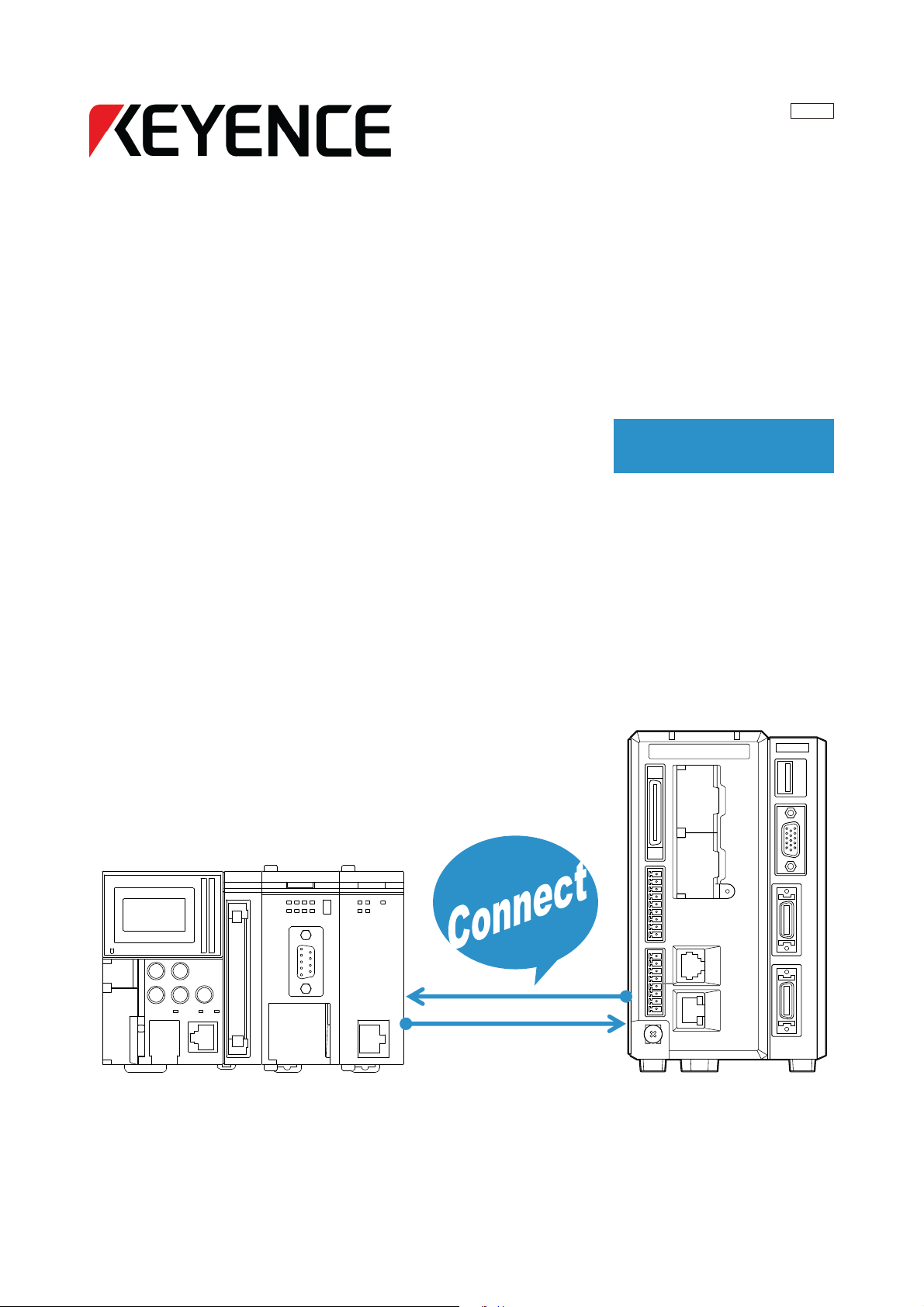
High-speed, High-capacity Machine Vision System
CV-X Series
Easy Setup Guide
365GB
Control/Communication EtherNet/IP
(KEYENCE KV Series)
Page 2

Contents
Easy Setup Guide: Control/Communication EtherNet/IP (KEYENCE KV Series)
3
1. Before Connecting EtherNet/IP
6
9
2. Outputting the Measured Value/Judged Value
3. Controlling the Controller
15
4. Data Allocation
5. Troubleshooting
17
Page
Page
Page
Page
Page
KEYENCE CORPORATION. Vision System Division
‐ 2 ‐ www.keyence.com
Page 3
1. Before Connecting EtherNet/IP (EtherNet/IP) [Keyence KV Series]
3
This section describes how to establish EtherNet/IP.
[Important]
If it fails, establish a one-to-one connection between the
PLC and CV-X, and follow this manual to configure the
settings and check the operations.
Confirm that it operates properly, and change settings if
necessary.
1. Checking the Global Settings of the CV-X100 Series
1
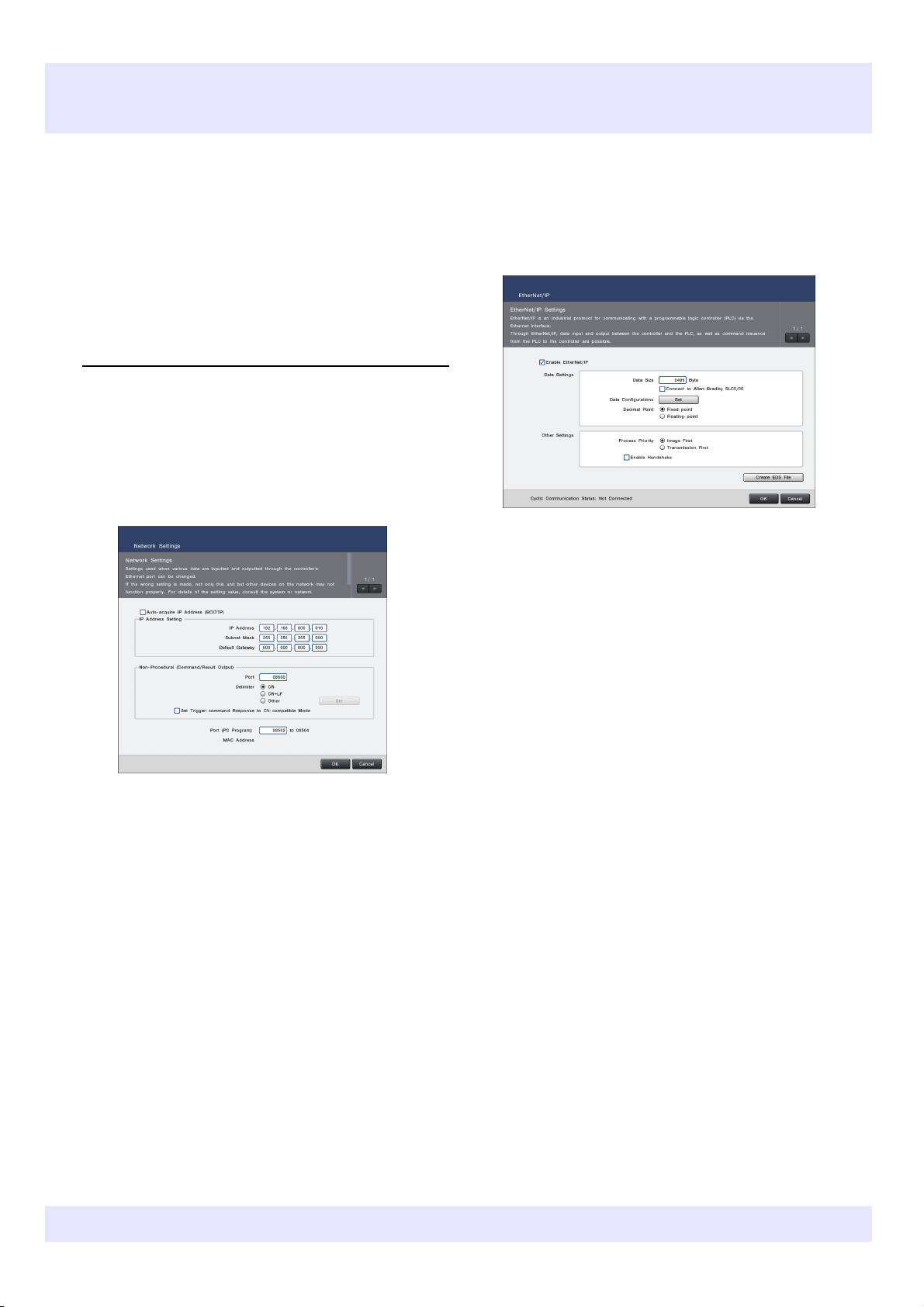
From "Global", select "Communications & I/O" "Network".
2
Change the Ethernet settings and then left-click
"OK".
From "Global", select "Communications & I/O" "EtherNet/IP".
4
Change the EtherNet/IP settings and then left-click
"OK".
In this section, the set values below will be
configured as an example (change the settings
according to the target device).
In this section, the set values below will be configured
as an example (change the settings according to the
target device).
•IP Address: 192.168.0.10
•Subnet Mask: 255.255.255.0
•Enable EtherNet/IP: Check this box.
•Data Size: 496 bytes
•Data Configurations: Set the desired data
allocations and allocation offset for the bit
address and byte address.
•Decimal Point: Fixed‐point
•Process Priority: Image First
5
Restart the controller.
KEYENCE CORPORATION. Vision System Division
365GB
‐ 3 ‐ www.keyence.com
Page 4
2. Changing the KV-Series settings
2
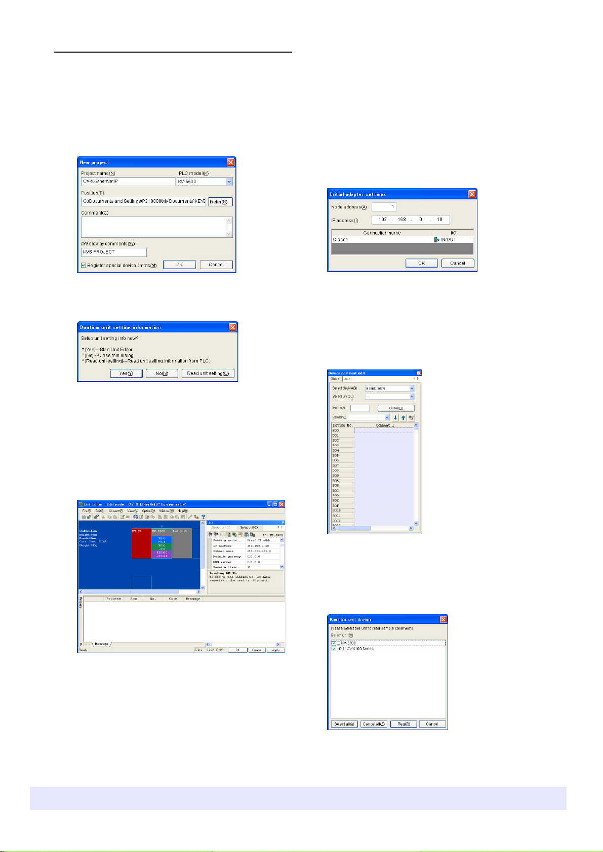
Enter the "Project name", select the "PLC model",
A "Confirm unit setting information" dialog appears.
3
Click "Read unit setting".
4
In the workspace, click the Ethernet/IP
5
Select "Convert" - "Auto-assign relay/DM" in the
6
Click the icon in "Setup unit (2)" to open
7
Save the changes and exit the "EtherNet/IP
8
Select "Device comment edit window" from the
9
Click "Details".
10
Confirm that the box for "CV-X100" is checked in
Device comments regarding CV‐X100 are
1
Start KV STUDIO with the PLC connected to the
computer, and select "New project" from the
"File" menu.
and then press "OK".
"EtherNet/IP settings". Configure the CV-X100
Series and EtherNet/IP communication settings.
•Drag "CV‐X100" from the "Unit list (1)" tab in
erNet/IP settings" and drop it into the scan list
"Eth
to add it.
•In the "Initial adapter settings" screen that is
displ
ayed after start up, enter the CV
dress (192.168.0.10) that was set in the
IP Ad
CV‐X100
Series global settings.
‐100 S
settings" and Unit Editor.
"Display" menu in KV STUDIO.
The "Device comment edit" screen appears.
eries
communication unit or CPU unit that will be
connected to the CV-X100 Series to start "Unit
Editor". Set up the IP Address of the KV Series in
the "Setup unit (2)" tab.
•IP Address: 192.168.0.20
•Subnet Mask: 255.255.255.0
Unit Editor to allocate a device.
When automatically allocated, the bit device is
allocated to B (link relay) and the byte device is
allocated to W (link register).
The "Register unit device" screen appears.
the "Select unit" list, and then click "Register".
KEYENCE CORPORATION. Vision System Division
automatically registered.
‐ 4 ‐ www.keyence.com
Page 5

11
Select "Transfer to PLC" from the
"Monitor/Simulator" menu in KV STUDIO.
12
Restart both the CV-X100 Series and the KV Series.
If the LINK LED on the KV Series Ethernet port stays lit
When the connection is successful, the LINK LED
(green) will start flashing on the KV Series Ethernet
port.
Successful connection can also be confirmed by
selecting "Communications & I/O"
"Global" on the CV
"Cyclic Communication Status".
(does not flash) or does not light
The EtherNet/IP may not be set up correctly, the cables may
not be connected correctly, or the CV
be started up. Check the connection equipment (if a
crossover cable is being used as a LAN cable when
connected directly, if the HUB is working, etc.)
Series, and checking the
‐X100
‐X100
rNet/IP" in
‐ "Ethe
Series may not
KEYENCE CORPORATION. Vision System Division
‐ 5 ‐ www.keyence.com
Page 6
2. Outputting the Measured Value/Judged Value (EtherNet/IP) [Keyence KV Series]
Use the output settings to output the measured values
1
Check an example of result data stored to the
Outputting the Measured Value/Judged
3
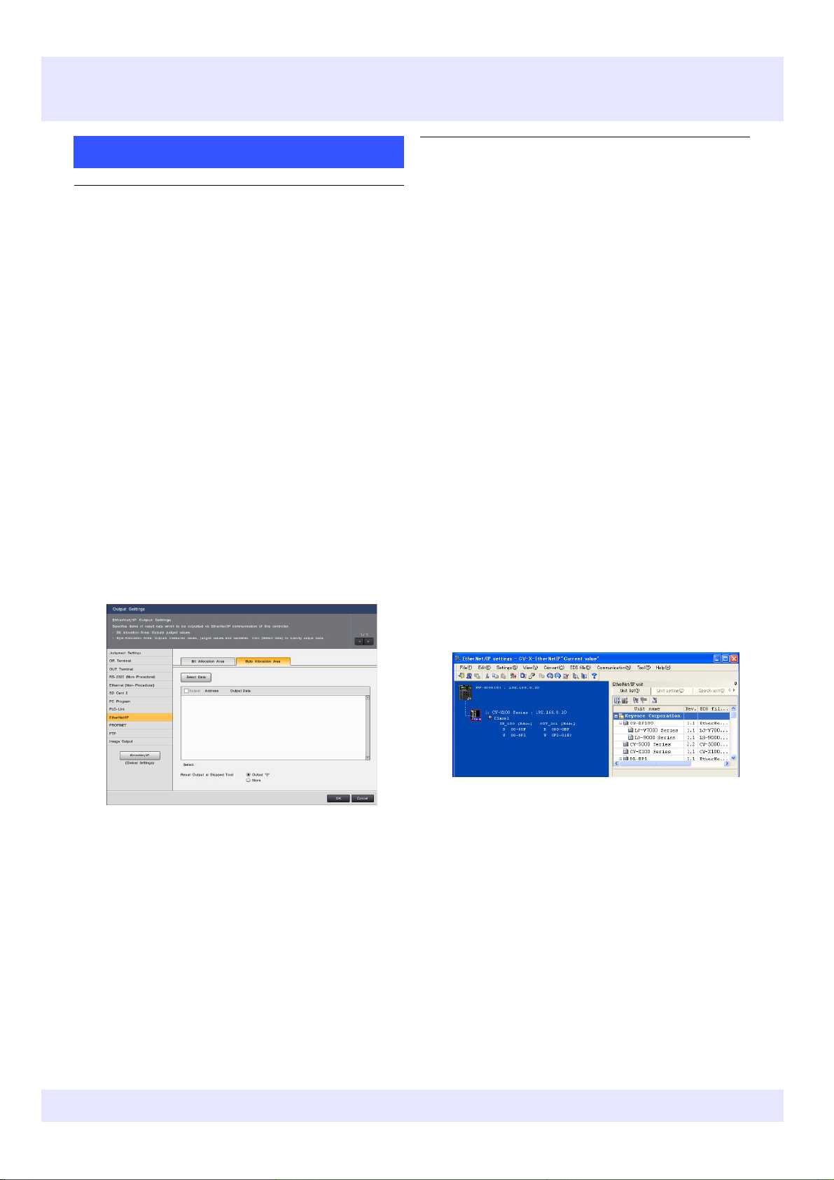
Left-click "Select Data", select the items to output,
4
Check the byte address for output.
1
From the "Output Settings" screen, left-click
2
Left-click the "Byte Allocation Area" tab.
2
Check the relationship between the byte address
•Check the range (hexadecimal) of the link relay
2. Checking the format for output to the byte
address, and the relationship between the byte
1. Setting the output data (Output Settings)
address and the link register (W)
and judged values. This section explains how to
allocate the measured/judged values below as an
example.
•Total Status Value
•T100: Position Adjustment with Shading Pattern
(position X)
•T100: Position Adjustment with Shading Pattern
(position XY)
•T101: Area
•T102: OCR (Recognize Strings)
•T100: Position Adjustment with Shading Pattern
(tool judgment value)
•T101: Area (tool judgment value)
•Program Time
•Date & Time
"EtherNet/IP".
The EtherNet/IP output settings screen appears.
byte address.
The EtherNet/IP output settings are set so that the
result data shown below is output.
•Total Status Value
•T100: Position Adjustment with Shading Pattern
(position X)
•T100: Position Adjustment with Shading Pattern
(position XY)
•T101: Area
•T102: OCR (Recognize Strings)
•T100: Position Adjustment with Shading Pattern
(tool judgment value)
•T101: Area (tool judgment value)
•Program Time
•Date & Time
and the link register (W) in KV STUDIO.
Open "EtherNet/IP settings" from the "Setup unit (2)"
tab in KV STUDIO Unit Editor, and click the plus sign
(+) next to "Class1" for the registered CV
check the allocation status of the device. (In the
notation, output from CV
(input)".)
is treated as "IN
‐X100
‐X100
to
and then left-click "Add".
KEYENCE CORPORATION. Vision System Division
•When allocating output data, the destination byte
address is automatically displayed in "Address".
•The byte address starting position is the position
allocated to "Result Data1" on the "Data
igurations"
Conf
he example above, it is byte address 048.)
(In t
‐ "Send‐Data" ‐ "Vie
w List" screen.
(B)/link register (W) allocated to the registered
CV‐X100
changed
•Byte addresses 0000‐0011 are for the link relay
(fro
0012 onwards are for the link register. Allocation
begins at the start from W0000, with 1 register
used for each 2‐byte address.
‐ 6 ‐ www.keyence.com
Series controller. (The range can also be
as desired by clicking "Edit".)
m B0000 onwards), and byte addresses from
Page 7

6
Input the trigger to the CV-X100 Series, then check
3
From "Global", select "Communications & I/O" -
4
Left-click "View List" in "Send-Data".
•By default, "Result Data1" (first result output) is
5
Restart the controller.
•Judged value OK=0, NG=1 is stored using 2 words.
"EtherNet/IP", and left-click "Set" in "Data
Settings".
The "EtherNet/IP Communication Data Structure"
screen appears.
The contents that are allocated to the controller send
set for byte address 0048, and the result data is
allocated there.
•As re
sult data is output in 32
addresses are used for each piece of result data
(1 character in the case of text).
‐bit u
nits, 4
‐byte
the output results in the KV STUDIO registration
monitor.
Check the current value beginning with device W012.
•Decimal fraction data is multiplied by 1000 and
stored using 2 words: 124.121 → 124121
•When XY data is output, it is stored in order XY
using 2 words each.
•Integer data is stored unchanged using 2 words
•Text data is stored in ASCII code using 2 words
per character
‐ When
dev
character string. In this example, because the
OCR unit "Detected String" is output, the character
string is "KEYENCE" (7 characters). However
because 10 is set for "Characters" in "Block Set",
the 20 words (for 10 characters) from W042 to
W054 are used.
‐ When
used changes. If there is a possibility that it might
be changed, it is recommended that it be set at
the end of the output data.
•Judged value OK=0, NG=1 is stored using 2 words.
•System variable: Integer type: Stored using 2 words
as is
Decimal type: Multiplied by 1,000 and stored using
2 words
outputting with "String", the number of
ices used varies depending on the set
the characters setting is changed, the device
KEYENCE CORPORATION. Vision System Division
‐ 7 ‐ www.keyence.com
Page 8

KEYENCE CORPORATION. Vision System Division
‐ 8 ‐ www.keyence.com
Page 9

3. Controlling the Controller (EtherNet/IP) [Keyence KV Series]
5
Restart the controller.
1
From "Global", select "Communications & I/O" -
Controlling the Controller
2
Click "Set" in "Data Settings".
3
Left-click "View List" in "Send-Data" and "Receive-
4
Click "OK".
The changed settings are saved.
1. Checking the Global Settings of the CV-X100 Series
"EtherNet/IP".
The "EtherNet/IP Communication Data Structure"
screen appears.
Data" to check the status of byte address and bit
address allocation for the items that are required
for controller control.
Receive-Data (PLC to Controller: OUT)
•Command request flag: Turns OFF→ON when a
command is executed (bit).
•Command Number: Sets the command No. of the
command to execute (double word).
•Command Parameter#: Sets the No. # argument
for the command (word). (Whether or not there
are arguments depends on the command.)
Send-Data (Controller to PLC: IN)
•Command complete flag: Turns ON when the
command process is completed (bit).
•Command error flag: Turns OFF when the
command process is completed, and ON when
a failure occurs (bit).
•Command ready flag: Turns ON when ready to
receive the command process (bit).
•Command Result: Sets the command execution
results (0: Success, <Error code>: Failure)
(double word).
•Command Data#: Sets the command No. #
response data (word). (Whether or not there is
response data depends on the command.)
KEYENCE CORPORATION. Vision System Division
‐ 9 ‐ www.keyence.com
Page 10

KEYENCE CORPORATION. Vision System Division
‐ 10 ‐ www.keyence.com
Page 11

✎ Command Execution Procedure Example Save Settings (SS)
Here is an example of a command execution procedure. This section shows an example of executing the SS (Save Settings)
Check the SS (Save Settings) command operation.
4.Check if the values of the devices corresponding to
flag, and "0" into Command result.
command which does not use a command parameter. The screens with blue frames show when the "Registration monitor"
function of KV STUDIO is used for confirmation.
1. Enter "12", the SS command No., in the device
corresponding to the PLC Command Number (W0F4
in this example).
2. Enter "1" in the device corresponding to the PLC
Command request flag (B060 in this example).
3. The command is executed.
the PLC Command complete flag and Command
result (B00 and W04 respectively in this example)
have changed.
When the command is successful: CV‐X writes "1" into Command complete
When the command fails: CV‐X writes "1" into Command complete flag, and
an error code into Command result.
KEYENCE CORPORATION. Vision System Division
‐ 11 ‐ www.keyence.com
Page 12

4. Check if the values of the devices corresponding to
✎Command Execution Procedure Example Switch Program Setting No. (PW)
Here is an example of a command execution procedure. This section shows an example of executing the PW (Switch Program
Check the PW (Switch Program Setting No.) command operation.
1. Enter "24", the PW command No., in the device
Setting No.) command which uses command parameters. The screens with blue frames show when the "Registration monitor"
function of KV STUDIO is used for confirmation.
corresponding to the PLC Command number (W0F4 in
this example), and enter the switch target SD drive No.
and program number in the device corresponding to
Command Parameter (W0F6 and W0F8 in this
example).
The figure on the right shows an example of switching
to program number "11" on "SD1".
2. Enter "1" in the device corresponding to the PLC
Command request flag (B060 in this example).
3. The command is executed.
the PLC Command complete flag and Command
result (B00 and W04 respectively in this example)
have changed.
When the command is successful: CV‐X writes "1" into Command complete
flag, and "0" into Command result.
When the command fails: CV‐X writes "1" into Command complete flag, and
an error code into Command result.
KEYENCE CORPORATION. Vision System Division
‐ 12 ‐ www.keyence.com
Page 13

✎ Command Execution Procedure Example Rewrite Judgment Conditions (DW)
Here is an example of a command execution procedure. This section shows an example of executing the DW (Rewrite Judgment
Check the DW (Rewrite Judgment Conditions) command operation.
1. Enter "45", the DW command No., in the device
4. Check if the values of the devices corresponding to
complete flag, and "0" into Command result.
flag, and an error code into Command result.
Conditions) command which uses command parameters and specifies integer and fractional values. The screens with blue frames
show when the "Registration monitor" function of KV STUDIO is used for confirmation.
corresponding to the PLC Command number (W0F4 in
this example), and enter the parameters in order in the
devices corresponding to the Command parameter
(W0F6, W0F8, W0FA and W0FC in this example).
The figure on the right shows an example of rewriting
the lower limit of the area of "T101" to "900".
‐ Parameter 1 101 (Tool ID: 101)
meter 2 105 (judgment condition item ID for
‐ Para
ea")
"Ar
→For information about the judgment condition
i
tem ID, refer to the CV
‐ Parameter 3 1 (lower limit)
‐ Parameter 4 900000 (value)
→If "Decimal Point" is set to "Fixed- point", specify
he value multiplied by 1000 (900000)
t
→If "Decimal Point" is set to "Floating- point",
specify a single precision floating point number
(900.000).
‐X Seri
es user's manual.
2. Enter "1" in the device corresponding to the PLC
Command request flag (B060 in this example).
3. The command is executed.
the PLC Command complete flag and Command result
(B00 and W04 respectively in this example) have
changed.
When the command is successful: CV‐X writes "1" into Command
When the command fails: CV‐X writes "1" into Command complete
KEYENCE CORPORATION. Vision System Division
‐ 13 ‐ www.keyence.com
Page 14

✎Command Execution Procedure Example Rewrite Registered String (CW)
Here is an example of a command execution procedure. This section shows an example of executing the CW (Rewrite
Check the CW (Rewrite Registered String) command operation.
4. Check if the values of the devices
complete flag, and "0" into Command result.
flag, and an error code into Command result.
Registered String) command which uses command parameters and specifies a string. The screens with blue frames
show when the "Registration monitor" function of KV STUDIO is used for confirmation.
1. Enter "43", the CW command No., in the device
corresponding to the PLC Command number
(W0F4 in this example), and enter the parameters
in order in the devices corresponding to the
Command parameter (W0F6 to W0106 in this
example).
T102: To rewrite the registered string of the OCR
tool to "ABCDE", specify the following.
meter 1 102 (Tool ID: 102)
‐ Para
‐ Parameter 2 1 (In the case of "OCR": Always 1)
‐ Para
meter 3 1 (When specifying characters on
th
e PLC side: "1")
meter 4 65 (ASCII code for "A")
‐ Para
meter 5 66 (ASCII code for "B")
‐ Para
‐ Parameter 6 67 (ASCII code for "C")
‐ Para
meter 7 68 (ASCII code for "D")
‐ Para
meter 8 69 (ASCII code for "E")
meter 9 0 (0 at the end of the string)
‐ Para
2. Enter "1" in the device corresponding to the PLC
Command request flag (B060 in this example).
* The device to use is 1 word.
3. The command is executed.
corresponding to the PLC Command complete
flag and Command result (B00 and W04
respectively in this example) have changed.
When the command is successful: CV‐X writes "1" into Command
When the command fails: CV‐X writes "1" into Command complete
KEYENCE CORPORATION. Vision System Division
‐ 14 ‐ www.keyence.com
Page 15

4. Data Allocation
KEYENCE CORPORATION. Vision System Division
‐ 15 ‐ www.keyence.com
Page 16

KEYENCE CORPORATION. Vision System Division
‐ 16 ‐ www.keyence.com
Page 17

5. Troubleshooting
KEYENCE CORPORATION. Vision System Division
‐ 17 ‐ www.keyence.com
Page 18

KEYENCE CORPORATION. Vision System Division
.
from [Image First]
‐ 18 ‐ www.keyence.com
Page 19

Page 20

Copyright (c) 2014 KEYENCE CORPORATION. All rights reserved. 124294E 1084-1 365GB Printed in Japan
 Loading...