

Page 1
Communication Software
with Simulator for Use with
CV-5001 Series Controller
CV-H5N
User's Manual
Read this manual before using the software in order to achieve
maximum performance.
Keep this manual in a safe place for future reference.
96095E
Page 2
Introduction
This manual describes the installation, use, procedures and cautions for the "CV-H5N Communication Software
with Simulator for Use with CV-5001 Series Controller." To get the most out of the CV-H5N Communication Software
be sure to read this manual. Always keep this manual in a safe place for future reference whenever needed.
■ Related manuals
Be sure to refer to the following manuals when using the CV-H5N.
CV-5001 Series
User’s Manual
This manual explains the specifications and functions of the CV-5001 super-high-speed
digital machine vision.
■ Symbols
The following warning symbols are used to ensure safety and to prevent injury and/or damage to property when
using the CV-5001 Series.
Danger
Indicates that the operator is at risk of death or serious physical injury if the system is improperly operated or this
precaution is not followed.
Warning
Indicates that the operator is at risk of physical injury if the system is improperly operated or this precaution is not
followed.
Caution
Indicates that property damage (including product malfunction) may occur if the system is improperly operated or
if this precaution is not followed.
Note
Indicates an important operating procedure that could be easily overlooked.
Reference
Indicates further information that may be useful to know.
CV-H5N-M-WW-NO0-E
Page 3

General Cautions
• Be sure that the CV-5001 Series machine vision system is operating correctly before using the CV-H5N
Communication Software
• Before starting work or before starting the system, confirm that all the functions of the system are working
.
properly.
• Be sure to configure the safety circuit without involving the machine vision system device in the circuit so
that the entire system ensures safety even when the machine vision system device malfunctions.
• The system may not operate correctly due to a possible output circuit or internal circuit malfunction. Be
sure to build a safety circuit for controls that may cause fire or major accident.
• If the system is used beyond published specifications or if the system is modified, the functions and
performance cannot be guaranteed.
• Please note that when the CV-5001 is used in combination with other instruments, its functions and
performance may be degraded.
• Do not use the CV-5001 for protecting the human body.
Request
Be sure to take safety precautions, like appropriate use within the rating and the intended performance
capabilities or installing fail safes, when using the CV-5001 Series and the CV-H5N software in the following
conditions or environment:
• Applications under conditions or environment not written in this manual.
• Applications involving atomic power plant control, railroad installations, airport installations, automotive,
combustible equipment, medical devices, amusement machines or safety equipment
• Applications in situations where there is a risk of loss of life, damage to property or extreme safety is
required
• Contact a Keyence representative with any questions or concerns.
Cautions
• Be sure to close Excel before starting CV-H5N Communication Software. Other applications do not need to
be shut down. However, it is recommended that they be closed as they may interfere with the performance
of this software.
• Do not run multiple instances of CV-H5N Communication Software on the same PC.
• The statistical analysis functions of this software can use data from the computer.
• A serial key is required to run the simulator.
To obtain a serial key, refer to "Obtaining a Serial Key for the Simulator" (page 1-12).
CV-H5N-M-WW-NO0-E
96095E
1
Page 4

Terms of Software License
NOTICE TO USER: PLEASE READ THIS SOFTWARE LICENSE AGREEMENT (“THIS AGREEMENT”)
CAREFULLY. BY USING ALL OR ANY PORTION OF THE CV-H5N (“THIS SOFTWARE”), YOU ARE
AGREEING TO BE BOUND BY ALL THE TERMS AND CONDITONS OF THIS AGREEMENT. IF YOU DO NOT
AGREE TO THE TERMS OF THIS AGREEMENT, DO NOT USE THIS SOFTWARE.
If you install, copy and or use all or a portion of this Software on a device or computer, you will be deemed to
have agreed to all the terms of this Agreement, and this Agreement will come into effect.
1. Definitions
1.1 “Use” or “using” refers to the accessing, installing, downloading, copying, operating and or otherwise
benefiting from the utilization of this Software.
1.2 “This Software” denotes the software and all associated documentation provided by KEYENCE.
1.3 “User” or “User’s” infers the company or persons who have had the license to use this Software granted
to them by KEYENCE.
2. Grant of License.
2.1 In compliance with all of the terms and conditions of this Agreement, KEYENCE grants the nonexclusive and non-transferable license to install and use this Software.
2.2 The granting of the license permits the single reproduction and or copying of this Software for the User’s
backing up or archiving purposes.
2.3. This Software maybe installed on multiple devices and computers for the User’s benefit and use.
2.4. The transfer of this Software via devices and computers with this Software installed on them by the User
to third parties is permitted. In such a case, the third party who receives this Software may continue to
use this Software in the same manner as the previous User.
2.5. With the transfer of this Software to a third party, the original User may install this Software to additional
devices and computers for further use as required. In such a case, the third party who receives this
Software may continue to use this Software in the same manner as the previous User.
2.6. The User maintains and guarantees that any thirdparties (as detailed in the previous two sections) who
receive and use this Software agree to this license Agreement and comply with all the terms and
conditions.
3. Restrictions.
3.1. This Software may not be modified by the User in any form except from the installation of updates or
new functions provided by KEYENCE.
3.2. The reverse engineering, decompiling or disassembling of this Software by any persons are not
permitted.
3.3. Without the prior permission of KEYENCE, the User may not reproduce or copy this Software for selling
or distributing to a third party
4. Intellectual Property Rights.
Except as expressly stated herein, KEYENCE reserves all right, title and interest in this Software, and all
associated copyrights, trademarks, and other intellectual property rights therein.
5. Disclaimer.
This Software is licensed to the User “AS IS” and without any warranty of any kind. In no event does
KEYENCE or its suppliers accept or assume any liability for any damages, claims, costs or profit loss as a
result of operating this Software.
2
CV-H5N-M-WW-NO0-E
Page 5

6. Termination.
6.1 Under this Agreement the User’s license will automatically terminate if this Software and any associated
copies of this Software are destroyed or voluntarily returned to KEYENCE.
6.2 Under this Agreement the User’s license will terminate immediately and automatically without any notice
from KEYENCE if there is any failure to comply with any of the terms and conditions of this Agreement.
Upon termination, the using of this Software shall cease, and all copies (full or partial) of this Software
should be destroyed or returned to KEYENCE.
6.3 Compensation will be sought by KEYENCE should any violation or breach of this Agreement result in
any incurred costs or lost profit to KEYENCE.
7. Governing Law.
7.1 This Agreement will be governed by and construed in accordance with the substantive laws of Japan.
7.2 If any part of this Agreement is found void and unenforceable, the rest of this Agreement will remain
intact, valid and enforceable according to the associated terms and conditions.
CV-H5N-M-WW-NO0-E
3
Page 6
Package Confirmation
Installer
PDF manual (cvh5n_users.pdf)
The following items are included in this package. Confirm that all of these items are included before use. While all items
should be included and functional, if an item is missing or broken, please contact your nearest KEYENCE sales office.
CV-H5N communication software for use with CV-5001 series (CD-ROM) ............................................................1
This CD-ROM includes installer, PDF manual and software for the communication software. Keep the CD in a
safe place once installation is complete.
Note
It is recommended that the software be backed up so that it can be recovered should the CD-ROM become damaged.
■ CD-ROM contents
[setup.exe] will run when the software is installed.
(It will start automatically at installation)
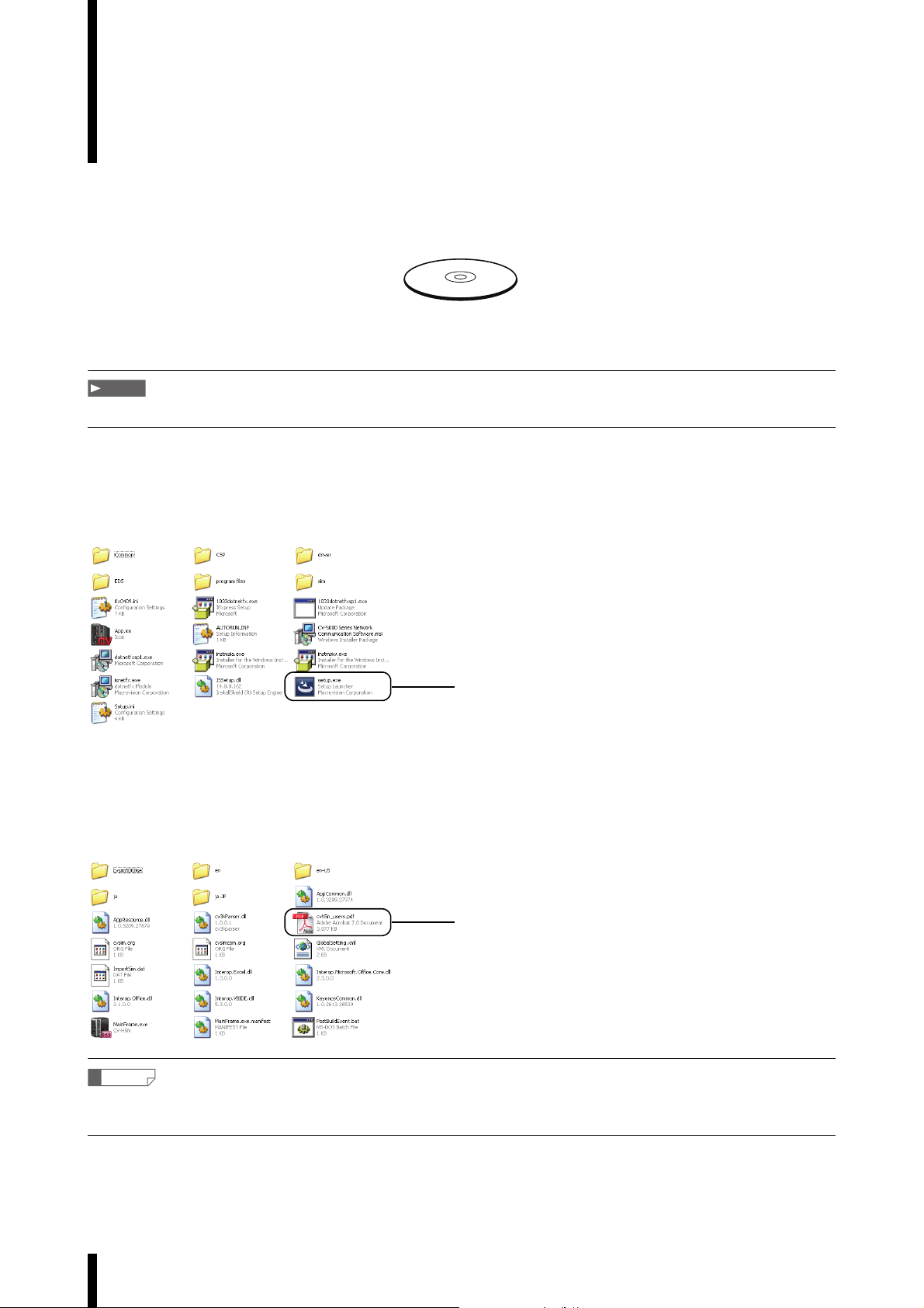
■ User’s manual storage location
The user’s manual for this software is found in the following location. (Assuming the CD-ROM is the D: drive)
D:\program files\KEYENCE Applications\CV-5001 Series Software\bin
Reference
• After installation, the PDF manual will be saved in the installation folder.
• A shortcut to the PDF manual will automatically be installed on the desktop of the computer.
4
CV-H5N-M-WW-NO0-E
Page 7
How this Manual is Organized
Chapter
1
Chapter
2
Chapter
3
Chapter
4
Appendix
Installation
Examples of
Software Use
Basic Operation
Detailed Software
Operation
Error Messages
Index
This chapter provides a list of package contents, an overview of the software
and an explanation of the conditions necessary for the operation of this device.
This chapter gives examples of functions of this software and their use.
This chapter describes the names and functions of the menu items and tools for
this software, as well as connecting this software with CV-5001 Series controller.
This chapter describes in detail the operation and settings of the menus,
including the Settings, Collection and Tools menus.
This chapter describes error messages.
1
2
3
4
A
CV-H5N-M-WW-NO0-E
5
Page 8

Table of contents
Introduction
General Cautions . . . . . . . . . . . . . . . . . . . . . . . . . . . . . . . . . . . . . . . . . . . . . . . . . . . . . . . . . . . . . . . . . . . . . . 1
Request . . . . . . . . . . . . . . . . . . . . . . . . . . . . . . . . . . . . . . . . . . . . . . . . . . . . . . . . . . . . . . . . . . . . . . . . . . . . . 1
Cautions . . . . . . . . . . . . . . . . . . . . . . . . . . . . . . . . . . . . . . . . . . . . . . . . . . . . . . . . . . . . . . . . . . . . . . . . . . . . . 1
Terms of Software License . . . . . . . . . . . . . . . . . . . . . . . . . . . . . . . . . . . . . . . . . . . . . . . . . . . . . . . . 2
How this Manual is Organized . . . . . . . . . . . . . . . . . . . . . . . . . . . . . . . . . . . . . . . . . . . . . . . . . . . . . 5
Table of contents . . . . . . . . . . . . . . . . . . . . . . . . . . . . . . . . . . . . . . . . . . . . . . . . . . . . . . . . . . . . . . . 6
Chapter 1 Installation
Software Overview . . . . . . . . . . . . . . . . . . . . . . . . . . . . . . . . . . . . . . . . . . . . . . . . . . . . . . . . . . . . .1-2
Application System Configuration . . . . . . . . . . . . . . . . . . . . . . . . . . . . . . . . . . . . . . . . . . . . . . . . .1-3
Operating Configuration . . . . . . . . . . . . . . . . . . . . . . . . . . . . . . . . . . . . . . . . . . . . . . . . . . . . . . . . .1-4
Installation . . . . . . . . . . . . . . . . . . . . . . . . . . . . . . . . . . . . . . . . . . . . . . . . . . . . . . . . . . . . . . . . . . .1-5
Installing from CD-ROM Files . . . . . . . . . . . . . . . . . . . . . . . . . . . . . . . . . . . . . . . . . . . . . . . . . . . . . . . 1-5
Installing from Downloaded Files . . . . . . . . . . . . . . . . . . . . . . . . . . . . . . . . . . . . . . . . . . . . . . . . . . . . 1-7
Uninstallation . . . . . . . . . . . . . . . . . . . . . . . . . . . . . . . . . . . . . . . . . . . . . . . . . . . . . . . . . . . . . . . .1-10
Cautions when using with Windows Vista or later version of OS . . . . . . . . . . . . . . . . . . . . . . . . .1-11
Obtaining a Serial Key for the Simulator . . . . . . . . . . . . . . . . . . . . . . . . . . . . . . . . . . . . . . . . . . .1-12
Chapter 2 Examples of Software Use
Example 1: Using the Simulator . . . . . . . . . . . . . . . . . . . . . . . . . . . . . . . . . . . . . . . . . . . . . . . . . . .2-2
Using the Simulator with a Sample File . . . . . . . . . . . . . . . . . . . . . . . . . . . . . . . . . . . . . . . . . . . . . . . 2-2
Simulation Using Programs and Image Data on an SD Card. . . . . . . . . . . . . . . . . . . . . . . . . . . . . . 2-10
Using the Simulator when Communicating with a CV-5001 Series . . . . . . . . . . . . . . . . . . . . . . . . . 2-20
Editing a CV-5001 Series Controller Program File on the Computer . . . . . . . . . . . . . . . . . . . . . . . . 2-22
Example 2: Creating a Log File and Displaying it with Excel . . . . . . . . . . . . . . . . . . . . . . . . . . . .2-28
Creating a Log File and Displaying it with Excel . . . . . . . . . . . . . . . . . . . . . . . . . . . . . . . . . . . . . . . 2-28
Example 3: Displaying Output Data . . . . . . . . . . . . . . . . . . . . . . . . . . . . . . . . . . . . . . . . . . . . . . .2-33
Displaying Output Data . . . . . . . . . . . . . . . . . . . . . . . . . . . . . . . . . . . . . . . . . . . . . . . . . . . . . . . . . . 2-33
Example 4: Saving and Displaying OK or NG Images . . . . . . . . . . . . . . . . . . . . . . . . . . . . . . . . .2-37
Saving and Displaying OK or NG Images . . . . . . . . . . . . . . . . . . . . . . . . . . . . . . . . . . . . . . . . . . . . 2-37
Chapter 3 Basic Operation
Starting Up and Shutting Down . . . . . . . . . . . . . . . . . . . . . . . . . . . . . . . . . . . . . . . . . . . . . . . . . . .3-2
Starting the Software. . . . . . . . . . . . . . . . . . . . . . . . . . . . . . . . . . . . . . . . . . . . . . . . . . . . . . . . . . . . . . 3-2
Shutting Down the Software . . . . . . . . . . . . . . . . . . . . . . . . . . . . . . . . . . . . . . . . . . . . . . . . . . . . . . . . 3-2
Names and Functions of Screen Elements . . . . . . . . . . . . . . . . . . . . . . . . . . . . . . . . . . . . . . . . . .3-3
6
CV-H5N-M-WW-NO0-E
Page 9

Connecting to a CV-5001 Series Controller . . . . . . . . . . . . . . . . . . . . . . . . . . . . . . . . . . . . . . . . . .3-6
Before Connecting . . . . . . . . . . . . . . . . . . . . . . . . . . . . . . . . . . . . . . . . . . . . . . . . . . . . . . . . . . . . . . . 3-6
Settings for a 1-to-1 Ethernet Connection. . . . . . . . . . . . . . . . . . . . . . . . . . . . . . . . . . . . . . . . . . . . . . 3-7
Settings for a LAN Ethernet Connection . . . . . . . . . . . . . . . . . . . . . . . . . . . . . . . . . . . . . . . . . . . . . . . 3-9
Connecting via USB . . . . . . . . . . . . . . . . . . . . . . . . . . . . . . . . . . . . . . . . . . . . . . . . . . . . . . . . . . . . . 3-10
Settings for an RS-232C Connection . . . . . . . . . . . . . . . . . . . . . . . . . . . . . . . . . . . . . . . . . . . . . . . . 3-13
Obtaining CV-5001 Series Controller Output Configuration Data from a Computer . . . . . . . . . . . . 3-15
Menu Bar . . . . . . . . . . . . . . . . . . . . . . . . . . . . . . . . . . . . . . . . . . . . . . . . . . . . . . . . . . . . . . . . . . .3-16
Toolbars . . . . . . . . . . . . . . . . . . . . . . . . . . . . . . . . . . . . . . . . . . . . . . . . . . . . . . . . . . . . . . . . . . . .3-20
Chapter 4 Detailed Software Operation
File . . . . . . . . . . . . . . . . . . . . . . . . . . . . . . . . . . . . . . . . . . . . . . . . . . . . . . . . . . . . . . . . . . . . . . . . .4-2
Creating a New Program File . . . . . . . . . . . . . . . . . . . . . . . . . . . . . . . . . . . . . . . . . . . . . . . . . . . . . . . 4-2
Opening a Program File . . . . . . . . . . . . . . . . . . . . . . . . . . . . . . . . . . . . . . . . . . . . . . . . . . . . . . . . . . . 4-3
Saving a Program File. . . . . . . . . . . . . . . . . . . . . . . . . . . . . . . . . . . . . . . . . . . . . . . . . . . . . . . . . . . . . 4-4
Saving a Program File. . . . . . . . . . . . . . . . . . . . . . . . . . . . . . . . . . . . . . . . . . . . . . . . . . . . . . . . . . . . . 4-4
Shutting Down the Software. . . . . . . . . . . . . . . . . . . . . . . . . . . . . . . . . . . . . . . . . . . . . . . . . . . . . . . . 4-5
Opening the Most Recent Program File . . . . . . . . . . . . . . . . . . . . . . . . . . . . . . . . . . . . . . . . . . . . . . . 4-5
Connections . . . . . . . . . . . . . . . . . . . . . . . . . . . . . . . . . . . . . . . . . . . . . . . . . . . . . . . . . . . . . . . . . .4-6
Specifying a New Connection Point . . . . . . . . . . . . . . . . . . . . . . . . . . . . . . . . . . . . . . . . . . . . . . . . . . 4-6
Connecting to a Selected Connection Point. . . . . . . . . . . . . . . . . . . . . . . . . . . . . . . . . . . . . . . . . . . . 4-9
Disconnecting from a Selected Connection Point . . . . . . . . . . . . . . . . . . . . . . . . . . . . . . . . . . . . . . . 4-9
Verify Output Data . . . . . . . . . . . . . . . . . . . . . . . . . . . . . . . . . . . . . . . . . . . . . . . . . . . . . . . . . . . . . . 4-10
Creating a Log File . . . . . . . . . . . . . . . . . . . . . . . . . . . . . . . . . . . . . . . . . . . . . . . . . . . . . . . . . . . . . . 4-11
Saving Images . . . . . . . . . . . . . . . . . . . . . . . . . . . . . . . . . . . . . . . . . . . . . . . . . . . . . . . . . . . . . . . . . 4-14
Create Output Data Display . . . . . . . . . . . . . . . . . . . . . . . . . . . . . . . . . . . . . . . . . . . . . . . . . . . . . . . 4-16
Creating an Image Display . . . . . . . . . . . . . . . . . . . . . . . . . . . . . . . . . . . . . . . . . . . . . . . . . . . . . . . . 4-19
Exporting Measurement Results to an Excel File . . . . . . . . . . . . . . . . . . . . . . . . . . . . . . . . . . . . . . . 4-21
Editing Connection Settings . . . . . . . . . . . . . . . . . . . . . . . . . . . . . . . . . . . . . . . . . . . . . . . . . . . . . . . 4-24
Deleting Connection Settings . . . . . . . . . . . . . . . . . . . . . . . . . . . . . . . . . . . . . . . . . . . . . . . . . . . . . . 4-25
Data Collection . . . . . . . . . . . . . . . . . . . . . . . . . . . . . . . . . . . . . . . . . . . . . . . . . . . . . . . . . . . . . . .4-26
Global Connect. . . . . . . . . . . . . . . . . . . . . . . . . . . . . . . . . . . . . . . . . . . . . . . . . . . . . . . . . . . . . . . . . 4-26
Global Disconnect . . . . . . . . . . . . . . . . . . . . . . . . . . . . . . . . . . . . . . . . . . . . . . . . . . . . . . . . . . . . . . 4-26
Verifying CV-5001 Series Controller Output Data. . . . . . . . . . . . . . . . . . . . . . . . . . . . . . . . . . . . . . . 4-27
Enabling Data Collection . . . . . . . . . . . . . . . . . . . . . . . . . . . . . . . . . . . . . . . . . . . . . . . . . . . . . . . . . 4-28
Ending Data Collection . . . . . . . . . . . . . . . . . . . . . . . . . . . . . . . . . . . . . . . . . . . . . . . . . . . . . . . . . . . 4-28
Simulator . . . . . . . . . . . . . . . . . . . . . . . . . . . . . . . . . . . . . . . . . . . . . . . . . . . . . . . . . . . . . . . . . . .4-29
Selecting a Virtual CV . . . . . . . . . . . . . . . . . . . . . . . . . . . . . . . . . . . . . . . . . . . . . . . . . . . . . . . . . . . . 4-29
Starting the Simulator . . . . . . . . . . . . . . . . . . . . . . . . . . . . . . . . . . . . . . . . . . . . . . . . . . . . . . . . . . . . 4-30
Importing the Simulator of the CV-5001 Series First Edition. . . . . . . . . . . . . . . . . . . . . . . . . . . . . . . 4-34
Managing Virtual CVs (Adding, Editing, Copying, Deleting) . . . . . . . . . . . . . . . . . . . . . . . . . . . . . . 4-35
CV-H5N-M-WW-NO0-E
7
Page 10

Loading “Trigger” Image Data into the Simulator. . . . . . . . . . . . . . . . . . . . . . . . . . . . . . . . . . . . . . . 4-44
Reading and Writing Program Data from a CV-5001 Series Controller . . . . . . . . . . . . . . . . . . . . . . 4-50
Exporting Program Configurations to Excel . . . . . . . . . . . . . . . . . . . . . . . . . . . . . . . . . . . . . . . . . . . 4-60
Window . . . . . . . . . . . . . . . . . . . . . . . . . . . . . . . . . . . . . . . . . . . . . . . . . . . . . . . . . . . . . . . . . . . .4-66
Selecting a Window . . . . . . . . . . . . . . . . . . . . . . . . . . . . . . . . . . . . . . . . . . . . . . . . . . . . . . . . . . . . . 4-66
Tools . . . . . . . . . . . . . . . . . . . . . . . . . . . . . . . . . . . . . . . . . . . . . . . . . . . . . . . . . . . . . . . . . . . . . .4-67
Managing CV-5001 Series Controller Program Data . . . . . . . . . . . . . . . . . . . . . . . . . . . . . . . . . . . . 4-67
Exporting Program Configurations to Excel . . . . . . . . . . . . . . . . . . . . . . . . . . . . . . . . . . . . . . . . . . . 4-71
Communication Command Monitor . . . . . . . . . . . . . . . . . . . . . . . . . . . . . . . . . . . . . . . . . . . . . . . . . 4-77
Capturing the Display Screen. . . . . . . . . . . . . . . . . . . . . . . . . . . . . . . . . . . . . . . . . . . . . . . . . . . . . . 4-78
Prohibiting Transmission. . . . . . . . . . . . . . . . . . . . . . . . . . . . . . . . . . . . . . . . . . . . . . . . . . . . . . . . . . 4-79
Setting a Password . . . . . . . . . . . . . . . . . . . . . . . . . . . . . . . . . . . . . . . . . . . . . . . . . . . . . . . . . . . . . . 4-80
Help . . . . . . . . . . . . . . . . . . . . . . . . . . . . . . . . . . . . . . . . . . . . . . . . . . . . . . . . . . . . . . . . . . . . . . .4-83
Displaying the Help File . . . . . . . . . . . . . . . . . . . . . . . . . . . . . . . . . . . . . . . . . . . . . . . . . . . . . . . . . . 4-83
Displaying Version Information . . . . . . . . . . . . . . . . . . . . . . . . . . . . . . . . . . . . . . . . . . . . . . . . . . . . . 4-83
Appendix
Error Message List . . . . . . . . . . . . . . . . . . . . . . . . . . . . . . . . . . . . . . . . . . . . . . . . . . . . . . . . . . . . A-2
Index . . . . . . . . . . . . . . . . . . . . . . . . . . . . . . . . . . . . . . . . . . . . . . . . . . . . . . . . . . . . . . . . . . . . . . . A-4
8
CV-H5N-M-WW-NO0-E
Page 11

Installation
This chapter provides an overview of the software and an
explanation of the conditions necessary for the operation of this
device.
Software Overview. . . . . . . . . . . . . . . . . . . . . . . . . . . . . . . . . . . . 1-2
Application System Configuration . . . . . . . . . . . . . . . . . . . . . . . . 1-3
Chapter
Operating Configuration . . . . . . . . . . . . . . . . . . . . . . . . . . . . . . . 1-4
Installation . . . . . . . . . . . . . . . . . . . . . . . . . . . . . . . . . . . . . . . . . . 1-5
Uninstallation . . . . . . . . . . . . . . . . . . . . . . . . . . . . . . . . . . . . . . . 1-10
Cautions when using with Windows Vista or later version of OS. . . 1-11
Obtaining a Serial Key for the Simulator . . . . . . . . . . . . . . . . . . 1-12
CV-H5N-M-WW-NO1-E
1-1
Page 12
1
Software Overview
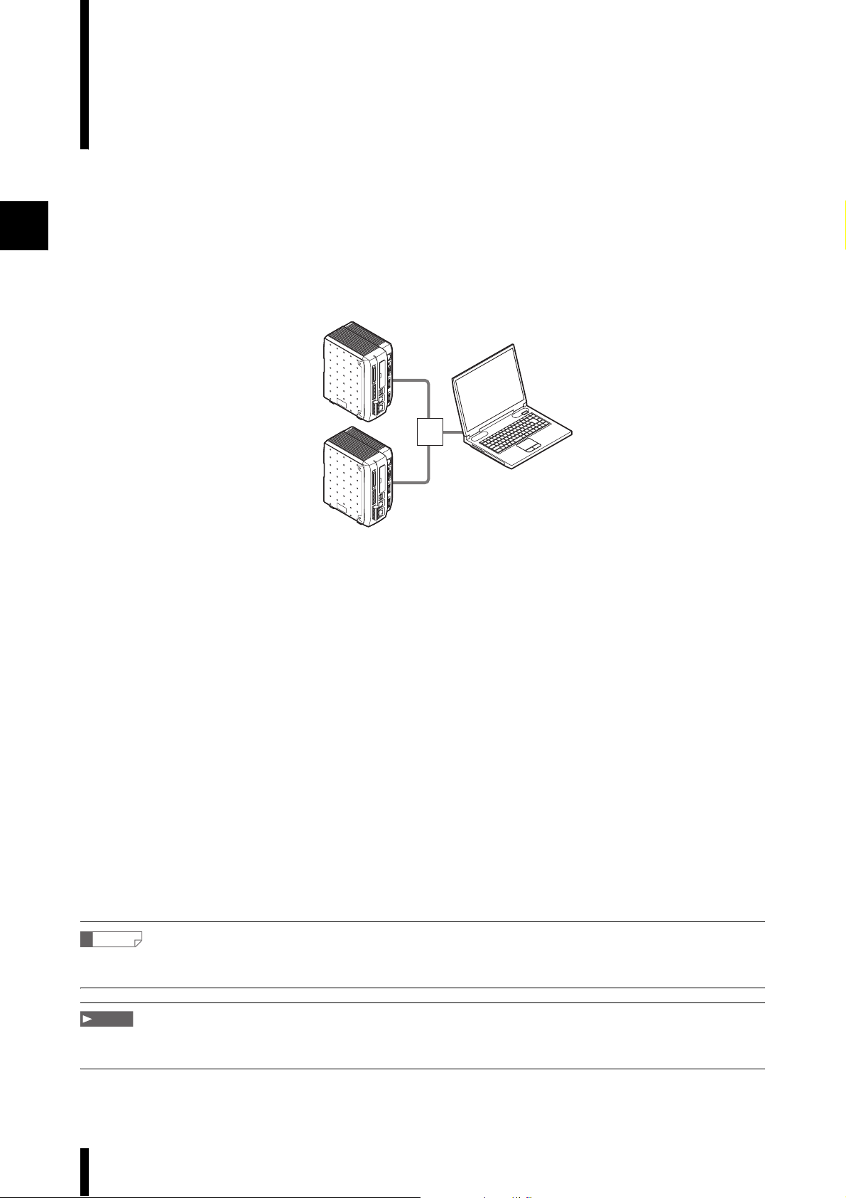
The CV-H5N communication software is for use with the CV-5001 Series machine vision system.
■ Overview
This software allows the user to acquire and store data from a CV-5001 Series controller to a computer via an
Ethernet, USB or RS-232 connection. Data can be displayed on the computer screen in real time and can be
output to an Excel file. Setting and image files from the CV-5001 can be backed up on the computer and loaded
into another CV-5001 unit. The CV-5001 settings can be edited and the results can be confirmed on a computer
using the Simulator feature.
Hub
(Router)
■ Software functions
1. Simulator
The operation of a CV-5001 can be simulated on a computer.
The simulator interface is designed to emulate the CV-5001 user interface exactly.
2. Data loading function
Data created on a CV-5001 Series controller can be loaded onto a computer and displayed in real time.
The computer can then determine if the output results are valid and save them.
3. Log creation function
Output data loaded from a CV-5001 Series controller can be saved in a log file according to preset conditions.
4. Exporting to an Excel file
Output data loaded from a CV-5001 Series controller can be saved in an Excel file.
5. Program data management and program parameter list creation
CV Program files, saved images and configuration files for the CV-5001 Series can be downloaded and saved on
a computer. Also, CV Program and image files saved on a CV-5001 Series controller or a computer can be loaded
into a different CV-5001 Series controller. CV Programs that have been loaded onto a computer can be displayed
and stored in Excel.
Reference
These functions can all be used with multiple CV-5001 Series controllers connected over a network (maximum 8 devices).
However, only one series controller can be connected via USB or RS-232.
Note
A serial key is required to run the simulator.
For more details, refer to "Obtaining a Serial Key for the Simulator" (page 1-12).
1-2
CV-H5N-M-WW-NO1-E
Page 13
Application System Configuration
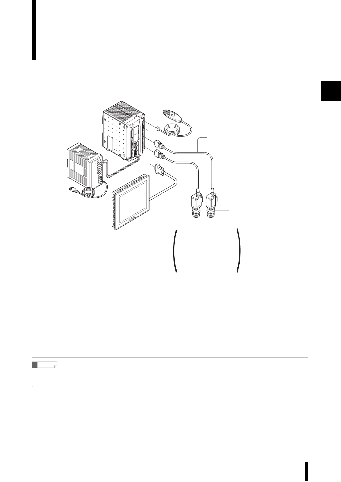
This example portrays a system with two cameras connected.
Controller unit
CV-5701/5501/5001
24VDC power supply
CA-U2 (Optional)
Monitor
CA-MP80
(Optional)
Console
(OP-42342)
SD card (256 MB)
(To be inserted in the SD card slot of the controller unit)
*1GB for the CV-5701
Camera cable
CV-C3 (3m) (Optional)
Lens (Optional)
Camera 1
CV-200C*1/CV-035C
CV-200M*1/CV-035M
CV-S200C*1/CV-S035C
CV-S200M*1 /CV-S035M
CV-H100C*1 /CV-H035C
CV-H100M*1/CV-H 035M
CV-H200C*1 /CV-H200M
CV-H500C*2 /CV-H500M
*1 Can be connected to the CV-5701 and CV-5501.
*2 Can be connected to the CV-5701 only.
Camera 2
(Sold separately)
*1
*2
1
■ Connector cable part numbers
• Ethernet : OP-66843
• USB : OP-66844
• RS-232C : OP-26486 (D-dub 9-pin female connector)
OP-26485 (D-dub 25-pin male connector)
OP-26487 (Straight cable)
Reference
Up to 8 devices can be connected on the network. However, only one CV-5001 Series controller can be connected via USB or
RS-232.
CV-H5N-M-WW-NO1-E
1-3
Page 14

Operating Configuration
Note
The following conditions must be met before using this software.
Computer specifications
1
Part IBM PC or PC/AT compatible (DOS/V)
Compatible OS Microsoft Windows 7 Home Premium/Professional/Ultimate/Enterprise
Microsoft Windows Vista Ultimate/Business/Premium/Basic/Enterprise
Microsoft Windows XP Professional/Home Edition
Microsoft Windows 2000 Professional SP 4 or later
• Supports the 64-bit version of Microsoft Windows 7 only.
For all other operating systems, only the 32-bit version is supported.
• Will not operate in XP compatibility mode for Windows 7
CPU Windows 2000/XP: Celeron 1.40 GHz equivalent or higher,
Core 2 Duo 1.80 GHz equivalent or higher is recommended
Windows Vista/7 : Core 2 Duo 1.06 GHz equivalent or higher,
Core 2 Duo 1.80 GHz equivalent or higher is recommended
Memory Windows 2000/XP: 512 MB or higher, 1 GB or higher is recommended
Windows Vista/7 : 1 GB or higher, 2 GB or higher is recommended
Free hard disk space 600 MB or more at time of installation (500 MB or more for use)
Display resolution 800x600 pixels High Color 65536 colors or more
(1280x1024 pixels or more, True Color, 24 bit or more, recommended)
CD-ROM drive Required for CD-ROM installation
Interface Ethernet port, USB port or RS-232C serial port
Excel Excel 2000/2002/2003/2007/2010
• Only one network card (wireless or not) can be used.
• Only one CV-5001 Series controller can be connected via USB.
1-4
CV-H5N-M-WW-NO1-E
Page 15
Installation
The files on the CD-ROM or the files that have been downloaded will be decompressed and installed as
specified on the screen.
Installing from CD-ROM Files
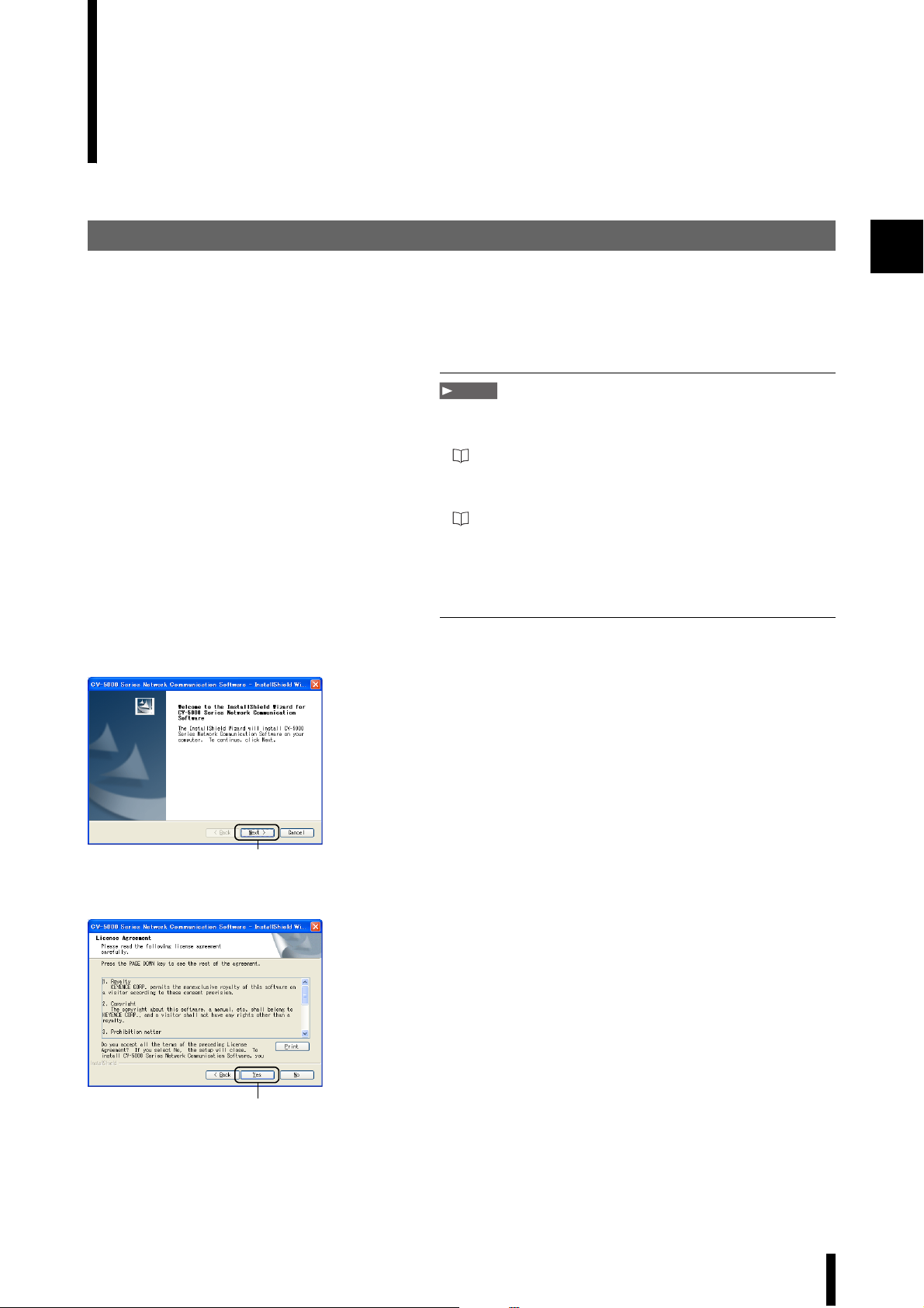
Insert the CD-ROM into the CD-ROM drive on the
1
computer.
The installer will start, and the “Welcome” screen of the
install wizard will appear.
Note
• If the installer does not start, run [setup.exe] from the CD-ROM to
begin installation.
Refer to page 3
• If an earlier version of the software has been installed, uninstall
the software before installing the new version.
For uninstalling the software, refer to "Uninstallation" (page 1-10).
• Install the software before connecting the OP-66844 USB cable
to the USB port of the CV-5001 Series controller.
• Installation must be done from an account with Administrator
rights.
1
Click the [Next] button.
2
The [License Agreement] menu appears.
2
Click the [Yes] button.
3
The [Customer Information] menu appears.
3
CV-H5N-M-WW-NO1-E
1-5
Page 16
1
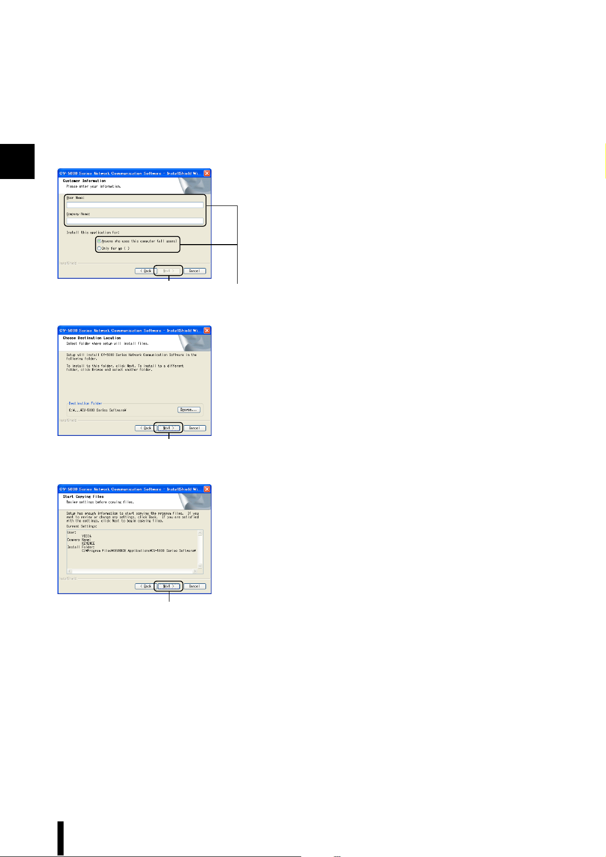
Enter customer information (User Name, Company
4
Name). Then specify the user.
Click the [Next] button.
5
The [Choose Destination Location] menu appears.
When installing to any location other than the default folder,
click the [Browse...] button and select a folder in the
[Choose Folder] menu.
5
4
Click the [Next] button.
6
The [Start Copying Files] menu appears.
6
Click the [Next] button.
7
Installation begins.
7
1-6
CV-H5N-M-WW-NO1-E
Page 17
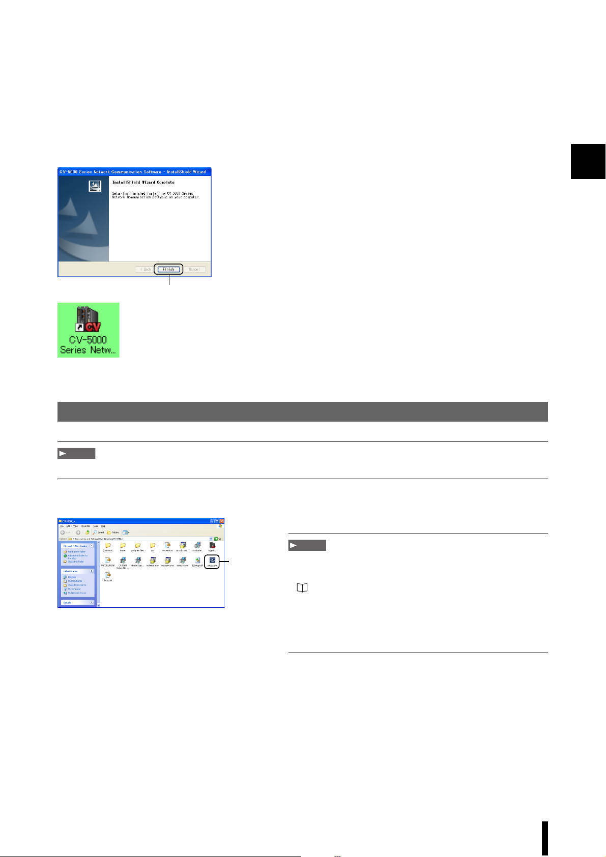
When installation is complete, the [InstallShield Wizard
8
Complete] screen will appear. Click [Finish] to end
installation.
Shortcuts for "CV-5000 Series Network Communication
Software" will appear on the desktop and under the
Windows [Start] menu in the [Network Communication
Software] section of the [CV-5000 Series] subfolder of the
[KEYENCE Applications] folder.
8
Installing from Downloaded Files
Note
Use decompression software to decompress the files. These files cannot be decompressed simply by double-clicking.
1
Start [setup.exe] from the folder to begin installation.
1
Note
1
• If an earlier version of the software has been installed, uninstall
the software before installing the new version.
For uninstalling the software, refer to "Uninstallation" (page 1-10).
• Install the software before connecting the OP-66844 USB cable
to the USB port on the CV-5001 Series.
• Installation must be done from an account with Administrator
rights.
CV-H5N-M-WW-NO1-E
1-7
Page 18
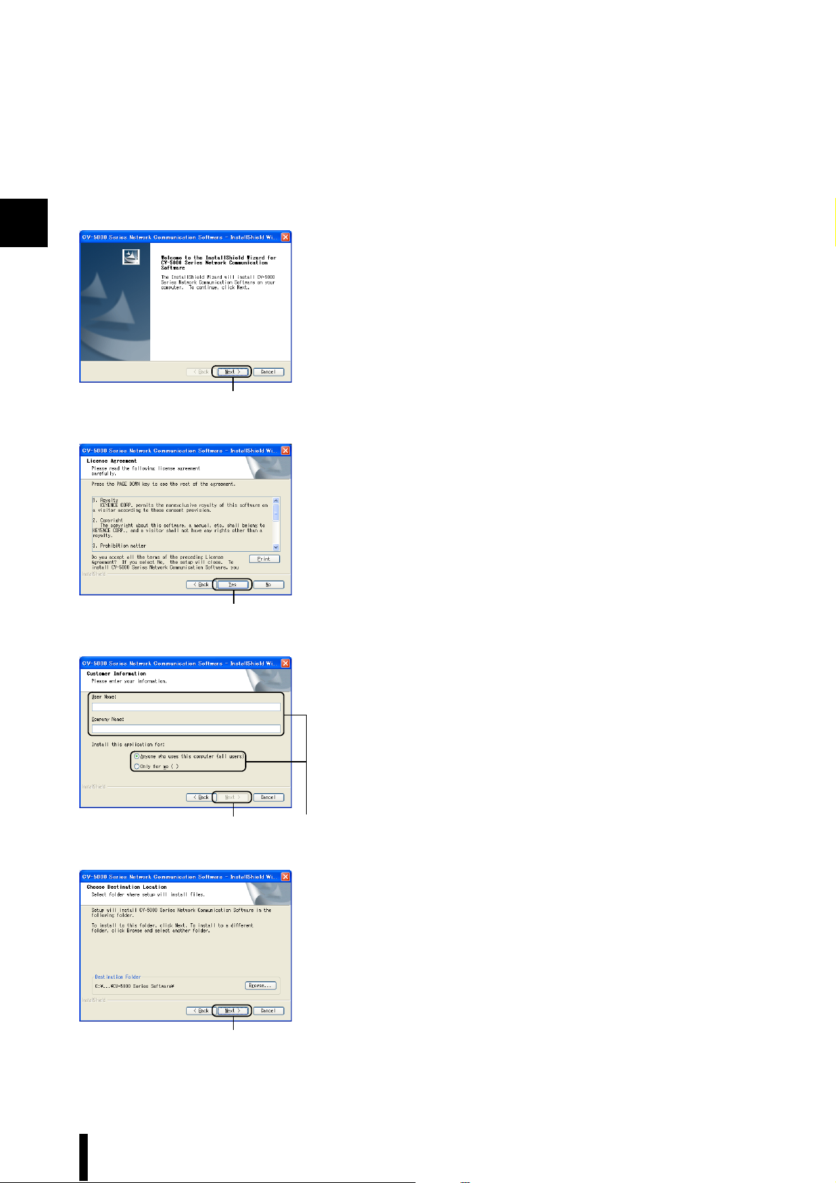
1
Click the [Next] button.
2
The [License Agreement] screen appears.
2
Click the [Yes] button.
3
The [Customer Information] dialog appears.
3
5 4
6
Enter the user information (User Name, Company name).
4
Then specify the user.
Click the [Next] button.
5
The [Choose Destination Location] screen appears.
To install to a folder other than the default folder, click the
[Browse] button and select a folder from the [Select
Directory] dialog.
Click the [Next] button.
6
The [Start Copying Files] screen appears.
1-8
CV-H5N-M-WW-NO1-E
Page 19
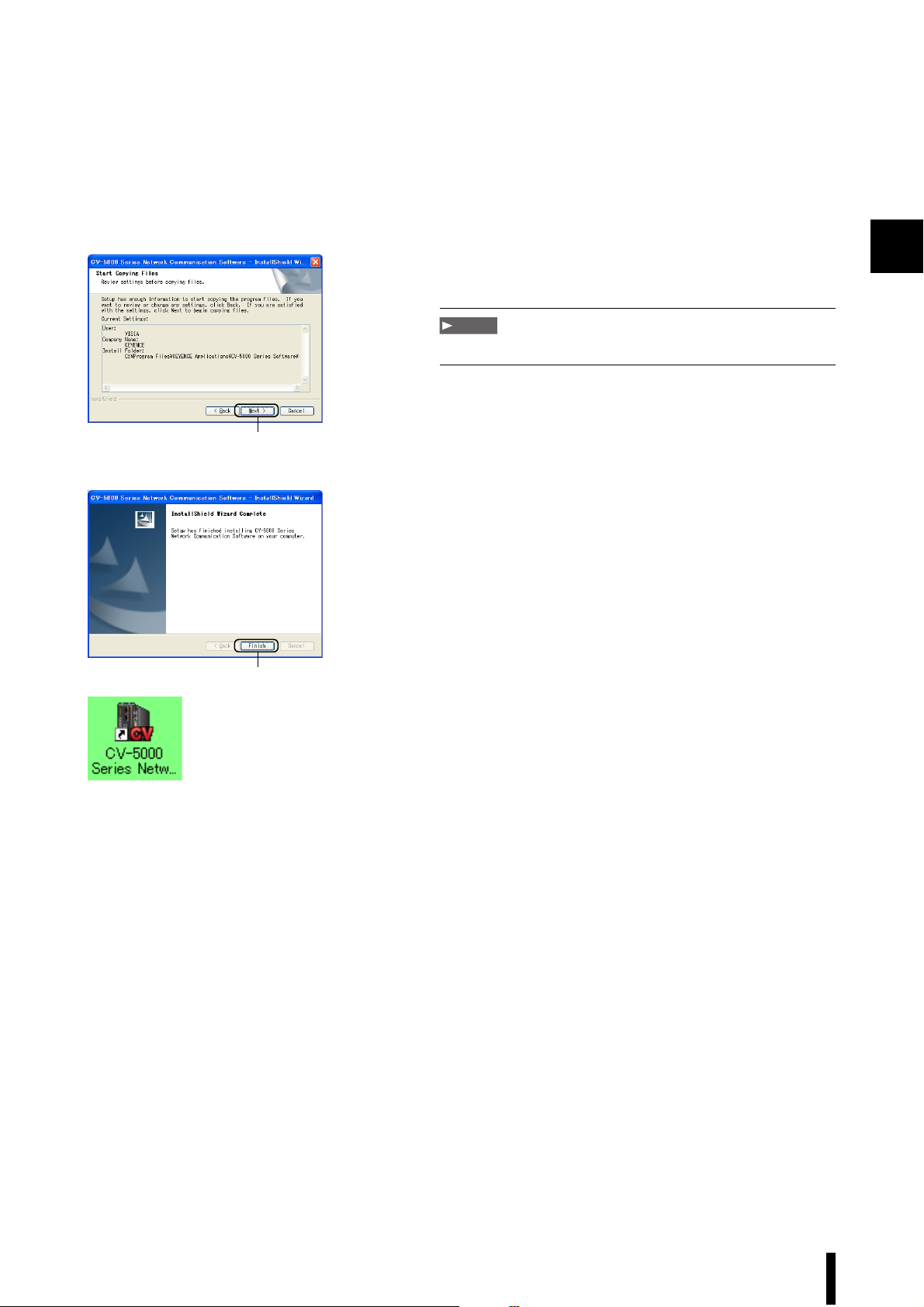
Click the [Next] button.
7
Installation begins.
Note
Installation may take several minutes.
1
7
When installation is complete, the [InstallShield Wizard
8
Complete] screen will appear. Click [Finish] to end
installation.
A “CV-5000 Series Network Communication Software”
shortcut will appear on the desktop. A similar shortcut will
appear under [Network Communication Software] in the
[CV-5000 Series] submenu of [KEYENCE Applications] on
the Windows [Start] menu.
8
CV-H5N-M-WW-NO1-E
1-9
Page 20
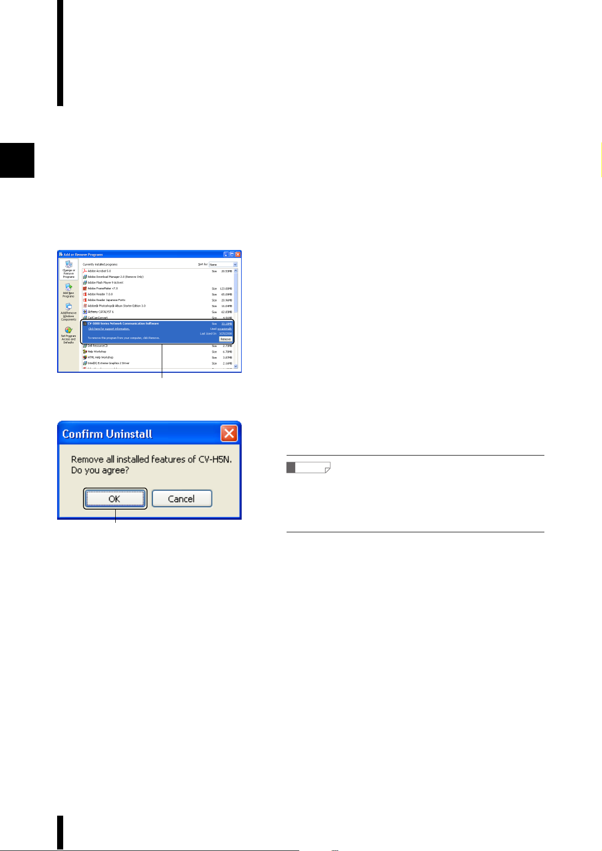
1
Uninstallation
To uninstall this software under Windows, go to [Control Panel] from the [Start] menu and select [Add or
Remove Programs].
Select [Control Panel] from the [Start] menu.
1
The [Control Panel] window appears.
Double-click the [Add or Remove Programs] icon.
2
The [Add or Remove Programs] window appears.
Select [CV-5000 Series Network Communication Software],
3
then select [Change/Remove]
[Confirm Uninstall] message appears.
3
Click the [OK] button.
4
The software will be removed.
Reference
• If a message asking to confirm deletion of shared files appears,
select [OK] to delete all of them.
• If uninstallation cannot be completed properly, run the installation
program again, then repeat the uninstallation procedure.
4
1-10
CV-H5N-M-WW-NO1-E
Page 21
Cautions when using with Windows Vista or later version of OS
If the simulator is started before the serial key is entered,
the ddscm.exe start confirmation dialog may appear twice.
Note
When the simulator is activated after import, re-entering the
serial key may be required. Additionally, it is not compatible
with import in a Windows 7 64-bit environment.
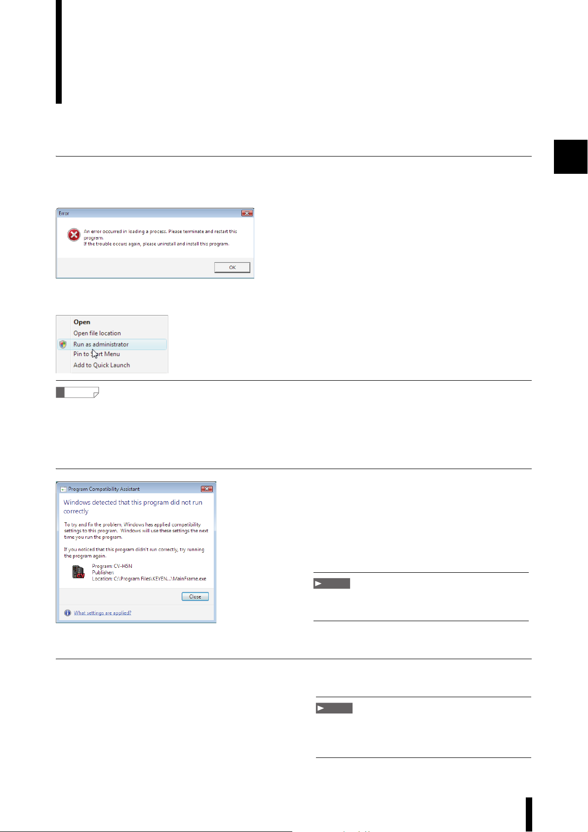
1. When starting the software for the first time
The following error may occur when [Start simulation] from the [Simulator] menu is clicked.
The software will need to be run in an account with administrator rights for the operation to be successful. If this is
not done, the following error will result.
Thus, do not start the software for the first time by double-clicking, but rather by selecting “Run as administrator”
from the right-click menu.
Reference
As a safeguard against compatibility issues when running applications designed for Windows XP applications under Windows
Vista/7, applications that generate compatibility warnings are automatically registered as programs to be run in XP compatibility
mode.
This software will terminate after the simulator fails to start and the following dialog will appear. The program chosen in this
dialog will be applied from the next time the dialog starts and the software will be usable.
1
2. When importing the simulator of the First Edition
Only a user with administrator rights can import the simulator of the First Edition.
CV-H5N-M-WW-NO1-E
Note
1-11
Page 22
1
Obtaining a Serial Key for the Simulator
A serial key from Keyence is required to run the simulator functions.
The procedure for obtaining a serial key is as follows.
Start the software.
1
2
3
Refer to "Starting the Software" (page 3-2) for information on
starting the software.
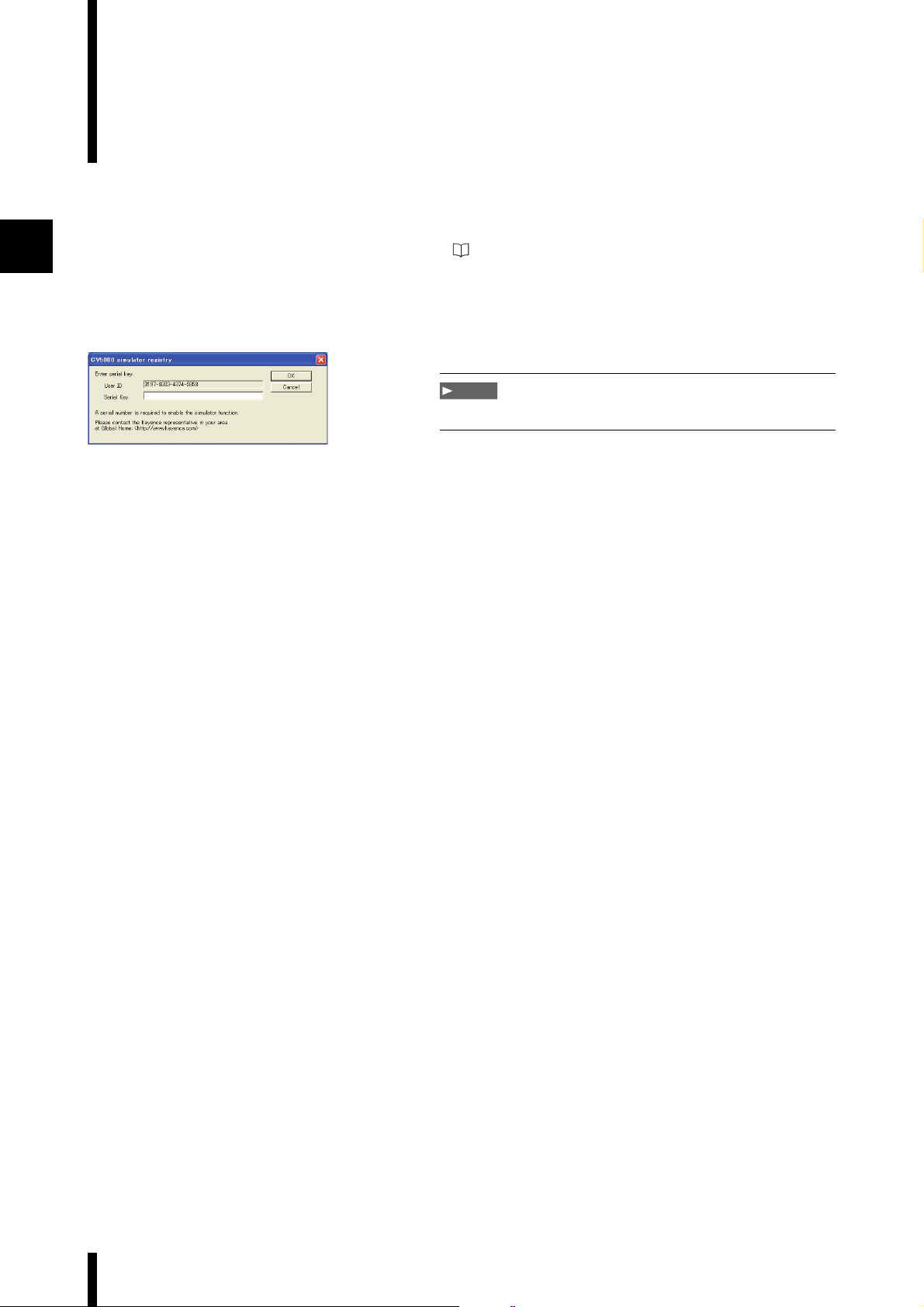
Select [Start simulation] from the [Simulator] menu.
The [CV5000 simulator registry] menu appears.
Note
The screens shown are only examples.
Write down the displayed [User ID (4 digit number-4 digit
number-4 digit number-4 digit number)] and store it in a
safe place. This will need to be input later.
To obtain the Serial Key for the simulator, please contact
4
the Keyence representative in your area at
Global Home: <http://www.keyence.com/>.
You will need to supply the User ID that is displayed when
the simulator is launched and your contact information.
1-12
CV-H5N-M-WW-NO1-E
Page 23
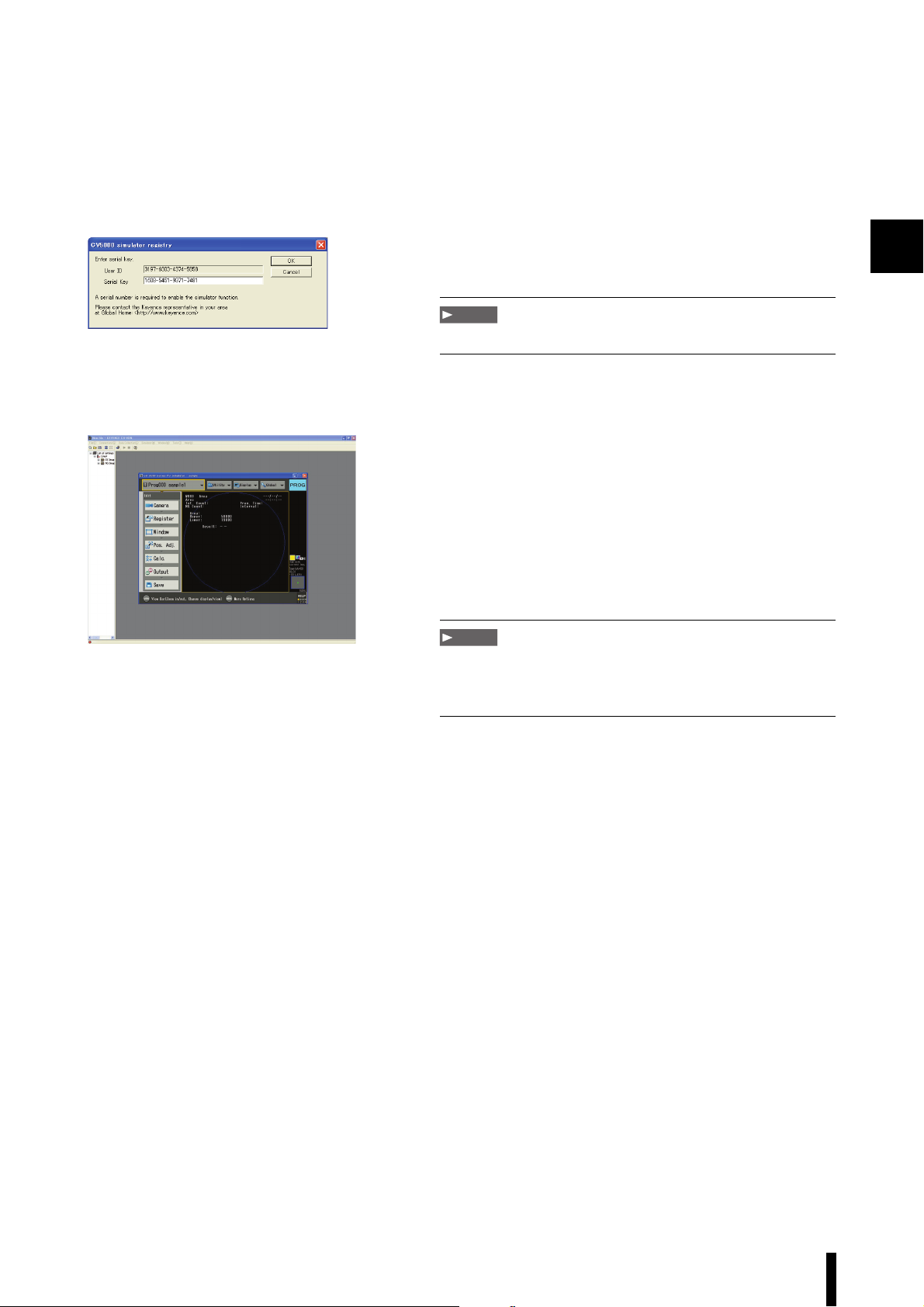
Enter the serial key obtained from the preceding
Example of the [CV5000 simulator registry] menu
5
procedure in the [Serial Key] text box of the [
simulator registry
Note
The screens shown are only examples.
The simulator screen appears.
Note
If the hardware configuration is changed, you will need to reinstall
the software and obtain a new serial key or return the computer to
the original hardware configuration.
] menu, then click [OK].
CV5000
1
CV-H5N-M-WW-NO1-E
1-13
Page 24

1
1-14
CV-H5N-M-WW-NO1-E
Page 25

Examples of Software Use
This chapter describes the representative functions of this software
and their use.
Example 1: Using the Simulator. . . . . . . . . . . . . . . . . . . . . . . . . . 2-2
Example 2: Creating a Log File and Displaying it with Excel . . 2-28
Example 3: Displaying Output Data . . . . . . . . . . . . . . . . . . . . . 2-33
Chapter
Example 4: Saving and Displaying OK or NG Images . . . . . . . 2-37
CV-H5N-M-WW-NO2-E
2-1
Page 26
2
Example 1: Using the Simulator
This section uses a sample file to explain the simulator.
Using the Simulator with a Sample File
1. Starting the simulator
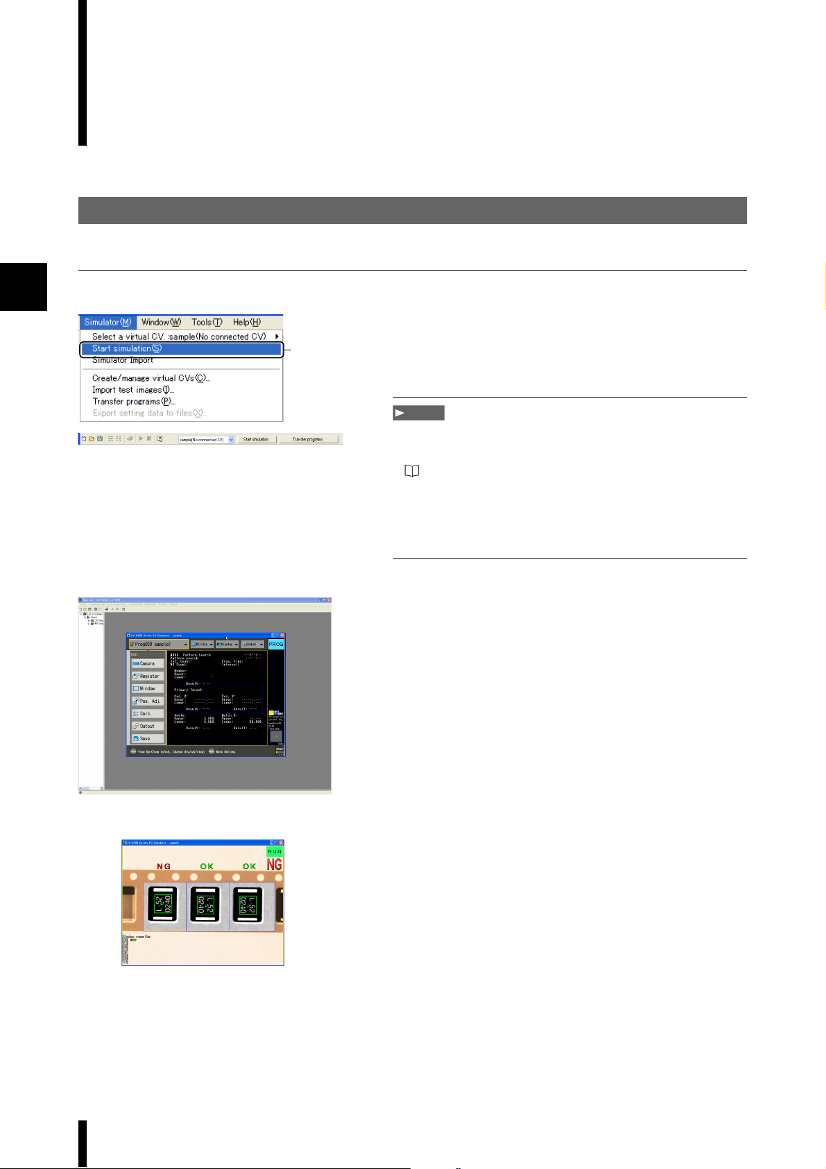
Select [Start simulation] from the [Simulator] menu.
1
1
The simulator screen appears. The settings for the sample
program (Virtual CV: sample) are selected. Start the
simulator.
Note
• Enter the serial key when the [CV5000 simulator registry] menu
appears.
For information about obtaining a serial key, refer to
"Obtaining a Serial Key for the Simulator" (page 1-12).
• It may take several minutes for the simulator to start.
• This function is not available while storing data. Suspend data
storing before proceeding with the simulator.
Press [T] on the keyboard to cycle through the saved
2
images.
2-2
CV-H5N-M-WW-NO2-E
Page 27
2. Using the simulator
Tabl e 1
Console menu and keyboard shortcuts
Console Keyboard
Enter Enter
Up n
Down p
Right o
Left m
Escape E or Esc
FNC F
TRG T
Screen S
View V
Menu M
Prog / Run P / R
Tabl e 2
Console menu and gamepad button
shortcuts (default settings)
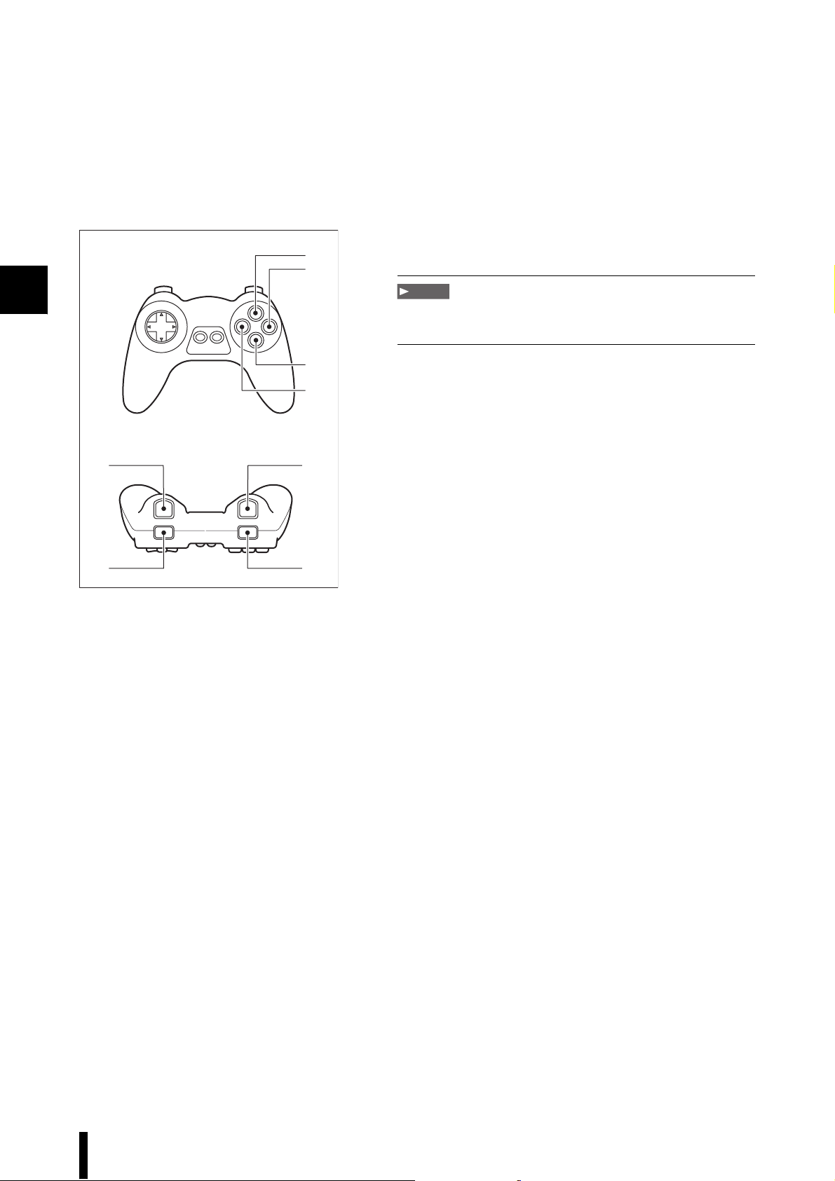
Operation of the simulator through the keyboard is the
1
same as through the CV remote console.
The relationship between console buttons and keyboard
keys is shown in Table 1.
Note
There is no keyboard key that corresponds to the button on the
under side of the remote (No.7)
For more information on operating a CV-5001 Series
controller, refer to the "CV-5001 Series User’s Manual," which
is packaged with any CV-5001 Series controller.
Note
There are some functions that cannot be performed with the
simulator.
For more information, refer to "Simulator" (page 4-29).
2
Console Gamepad
Enter 2
Up n
Down p
Right o
Left m
Escape 3
FNC 6
TRG 1
Screen 8
View 4
Menu 7
Prog / Run 5
Reference
As shown in Table 2, a gamepad can also be used to control the
device. Aside from the directional keys of the gamepad, all keys
can be freely reassigned.
For more information, refer to "Simulator" (page 4-29).
CV-H5N-M-WW-NO2-E
2-3
Page 28
2
Example of gamepad button layout
■Game pads certified by Keyence
Logitech
1
2
3
4
Precision Gamepad
Note
Use of gamepads not certified by Keyence may result in abnormal
operation.
5
7
6
8
2-4
CV-H5N-M-WW-NO2-E
Page 29
3. Differences Between the Simulator and the Actual CV-5001 Series
This section introduces the unique and convenient functions of the simulator that differentiate it from the CV-5001
device.
1. Name input via keyboard function
This function allows the computer keyboard to be used to enter names when the software keyboard is
displayed (including window names, calculation names and custom screen character input). This reduces the
time required to create multiple windows or calculations.
Reference
By using the Windows OS version that corresponds to the language selected in the Global setting, Japanese and Chinese
characters can be entered with the keyboard (See the following table).
However, special characters such as eszett or diacritics such as umlaut or accent marks cannot be entered.
Language selected in the Global setting Compatible Windows OS Input characters
2
Japanese Windows OS Japanese
(See specifications on page 1-4 for compatible versions)
Chinese (Simplified) Windows 2000/XP Simplified Chinese
Windows Vista/7 Chinese (PRC)
Chinese (Traditional) Windows 2000/XP Traditional Chinese
Windows 2000/XP Hong Kong
Windows Vista/7 Chinese (Hong Kong SAR)
Windows Vista/7 Chinese (Taiwan)
Other Windows OS for various languages
(See specifications on page 1-4 for compatible versions)
Note
When a program is created in Chinese (Traditional or Simplified) and then the language is switched (including between
Traditional and Simplified Chinese), the characters may not be displayed correctly.
Also, when a program is created in other languages than Chinese and then switched to Chinese (Traditional or Simplified), the
characters may not be displayed correctly.
To avoid this, use the Windows OS that is compatible with the language selected on the CV-5001 Series.
SJIS characters
GB13000 characters
BIG5 characters
ASCII characters
2. Special trigger function
The simulator has several unique triggers, including the loop trigger (press and hold T (TRG) for 3 or more
seconds), the reverse trigger (F + T (press TRG while holding FNC)) and the repeat trigger (S + T (Press TRG
while holding SCR)).
The loop trigger allows you to measure all of the images in an image folder with a single trigger, even if there
are more than 100 images. The results can be confirmed with statistical analysis.
The reverse trigger allows you to confirm the most recent NG image after changing programs.
The repeat trigger allows you to confirm results for the same image under different sets of detection conditions.
CV-H5N-M-WW-NO2-E
2-5
Page 30

2
There are 8 differences between the simulator and the physical device.
1. Measurement time / trigger delay
The hardware architecture of the computer and the device are different, so the same process may take a
different amount of time on one than on the other.
2. External input/output
General evaluations, terminal output, PLC- EIP - RS-232C, Ethernet, USB, and image output (except the memory
card) are not functional.
Output to SD2 acts as output to the Virtual CV D drive.
3. Image archive (utility)
No history is kept.
4. File manager (utility)
Unavailable.
5. Transferring programs and settings (global settings)
Unavailable.
6. Multi-Image Capture
The Multi-Image capture will not function if activated in the simulator. Normal measurement will be taken.
7. “Read” and “Write” under "Library settings" in OCR mode
Unavailable.
8. Differences in measurement results due to differences in hardware.
The differences between the calculation hardware in the PC and the device may result in the following
differences in measurement results.
• Recognition levels when library registration has been used in OCR or the simulator
• Digits two or more places after the decimal point in edge intensity and all forms of edge mode
• Digits two or more places after the decimal point in concentration detection mode and average concentration
9. Differences in camera settings
• Shutter speed, light intensity, or gain adjustment is not applied.
• The trigger delay is not applied.
• The continuous update of the window update mode is not applied.
2-6
CV-H5N-M-WW-NO2-E
Page 31
4. The Virtual CV
The simulator operating environment must be created before the simulator can be run. This environment is called
the “Virtual CV” and creates a virtual CV-5001 series on the computer.
Settings, including camera settings [Image folder and Image data] and drive path [select virtual C/D drive] can be
set so that the simulator operates on the PC as outlined below.
Note
To the Chinese Windows OS (Traditional or Simplified) users:
Use only single-byte alphanumeric characters for the following places. The software does not supports other characters.
Virtual CV Settings:
• Virtual CV name • Location of Test Image • Test Image File • Program Location
Windows account name
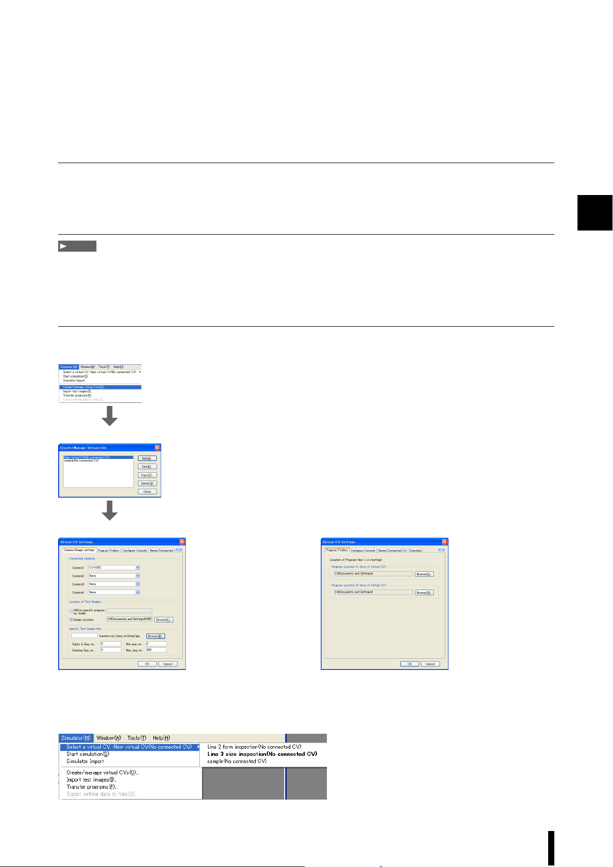
Simulator -> Create/manage virtual CVs
Line 3 size inspection(No connected CV)
2
Virtual CV Settings_Camera/Image settings Virtual CV Settings_Program Folders
There is no limit to the number of virtual CVs that may be created, a large number of different simulated
environments can be created and interchanged. This allows you to create simulator environments as needed for
each of the 8 possible CV-5001 series that can be connected.
Simulator -> Select a virtual CV. :Line 3 size inspection(No connected CV)
CV-H5N-M-WW-NO2-E
2-7
Page 32

2
5. Loading image data (from a digital camera or other digital imaging device)
Convert the image data into data that can be managed by
1
the ‘Sample’ simulator.
Use commercial image editing software to convert the
image to a 512 x 480 pixel, 24 bit color image.
The simulator can use the following types of image data.
The ‘Sample’ program can use [Color (VGA)] images.
Connected camera name
CV-035C/S035C
CV-035M/S035M
CV-200C/S200C
CV-200M/S200M
CV-H035C
CV-H035M
CV-H100C
CV-H200C
CV-H100M
CV-H200M
CV-H500C
CV-H500M
Select [Import test images] from the [Simulator] menu.
2
The [Import Test Images] menu appears.
Readable image data
512 x 480 pixels and 640 x 480 pixels / 24-bit
color BMP and JPEG
512 x 480 pixels and 640 x 480 pixels / 8-bit
grayscale BMP and JPEG
1600 x 1200 pixels and 1024 x 960 pixels / 24bit color BMP and JPEG
1600 x 1200 pixels and 1024 x 960 pixels /
8-bit grayscale BMP and JPEG
512 x 480 pixels and 640 x 480 pixels / 24-bit
color BMP and JPEG
512 x 480 pixels and 640 x 480 pixels / 8-bit
grayscale BMP and JPEG
1000 x 1000 pixels/ 24-bit color BMP and JPEG
1600 x 1200 pixels and 1024 x 960 pixels /
24-bit color BMP and JPEG
1000 x 1000 pixels / 8-bit grayscale BMP and JPEG
1600 x 1200 pixels and 1024 x 960 pixels /
8-bit grayscale BMP and JPEG
2432 x 2050 pixels / 24-bit color BMP and
JPEG
2432 x 2050 pixels / 8-bit grayscale BMP and JPEG
2
2-8
Click the [Browse...] button on the [Import from PC] tab
3
to display the [Open] menu.
3
CV-H5N-M-WW-NO2-E
Page 33

Select all of the image data to be loaded, then click the
4
[Open] button.
The data to be loaded will be displayed under [Filename
[before Import]] from the [Import Test Images] menu. Also,
data that has been converted into a format that is accessible
by the simulator will be displayed under [Filename [after
Import]].
4
5
Refer to "Loading “Trigger” Image Data into the Simulator"
(page 4-44) for more information on [Folder name] and [File
name].
Click the [Execute] button from the [Import Test Images]
menu.
A message will appear indicating that the data has been
transferred.
2
CV-H5N-M-WW-NO2-E
5
Click the [OK] button to end the process.
6
6
Reference
To modify the contents of the imported program and images, select
[Start simulation] from the [Simulator] menu. The [T] button on the
keyboard will cycle through all imported images.
For more information on the simulator and other functions,
refer to "Simulator" (page 4-29).
2-9
Page 34

Simulation Using Programs and Image Data on an SD Card
1. Read from the simulator with the SD card (SD2) as the virtual D drive
2
The procedure for inserting the SD card (SD2) from the CV-5001 series device into the computer and using the
saved data is outlined below.
SD card root folder
CV
Setting
000
001
005
The setting file
“cvset.dat” and the
image file “ref
1.000bmp” are
found here.
Each folder has a
setting folder, which
is associated with
one setting file.
Create a file on the SD card inserted into the CV-5001
1
series. If there is a program on the SD card, that file will
automatically be saved in a folder with a name
consisting of 3 digits (such as 000 or 150).
The folder is automatically created under [SD card root
folder – cv – setting], as shown below.
Take the SD card with the CV-5001 series program
2
created in step 1 and insert it into the computer.
Start the CV-H5N and select [Create/Manage Virtual CVs]
3
from the [Simulator] menu.
2-10
Select a Virtual CV, then click the [Edit] button.
4
Then select “Drive path” from the tab.
Click the [Browse] button next to [K drive location] and
select the drive with the SD card that was inserted in step 2.
Specify the SD card drive
(in this example, K:), then
click OK.
CV-H5N-M-WW-NO2-E
Page 35

Specifying the SD card drive as the
virtual D drive allows you to edit the
SD card programs in the simulator.
This does not specify the setting file name, but rather
specifies the drive on which the file is stored. (In this
example, D) This D drive is the “SD card root folder” from
step 1 and locations prefixed with "D:" are located on the
D drive.
The CV-5001 physical device and the simulator each
have levels below the drive level known as “cv”, “setting”
and “Program No. folder”.
Note
The simulator will not use these setting files (for example, folder
000) even if they are specified. Specify the setting file in the
structure of step 1 so that the location of the D drive is the folder
containing the “cv” folder.
2
CV-H5N-M-WW-NO2-E
2-11
Page 36

2
2. Load a program file into the simulator
The procedure for reading programs on the SD card to the virtual drive of the simulator is as follows:
Select [Transfer programs] from the [Simulator] menu.
1
The [Transfer Programs] menu appears.
Note
This function is not available while collecting data.
Suspend data collection before proceeding with the simulator.
A Information about [File type] is displayed.
• Read From
Select [File] (program data in the drive folder within
A
B
the computer).
[Connected CV] is grayed out if the connection
destination is not set in [Create/manage virtual
CVs].
• File Locations
Specify the program file to read from the drive
folder within the computer.
• File type
Select the data to read from the program number
specified in [File Location]. By default, [Program
Data], [Registered image], and [Library Data] are
on.
B Information about [Read to] is displayed.
• Virtual CV
The name of the selected Virtual CV is displayed.
• Save to/Program no.
This specifies the program number and the save
location. (See steps 4 and 5.)
2-12
Select [File] for [Read From].
2
• File
Select this to read the program data from the drive folder
within the computer, or to write the program data to the
drive folder within the computer.
• Connected CV
Select this to read/write the program data from/to the CV5001 Series controller connected to the computer.
CV-H5N-M-WW-NO2-E
Page 37

Select [File Location].
3
Select a program data folder within the computer or in the
external removable media.
Reference
The program number 005 saved on a memory card in the E drive
connected to the computer is selected in the example shown on the
left.
Select [Save to].
4
• Drive C of Virtual CV
Select this to write the program number data in the drive C
of virtual CV.
• Drive D of Virtual CV
Select this to write the program number data in the drive D
of virtual CV.
The default setting uses the program number currently
being used by the simulator.
2
CV-H5N-M-WW-NO2-E
Click the [Execute] button.
5
A confirmation message appears.
Click the [Yes] button.
6
A message will appear indicating that the data has been
successfully loaded.
2-13
Page 38

2
Click the [OK] button to return to the main window.
7
Reference
Using load target and global data
When global data is loaded from a CV-5001 Series controller, the
program no. currently being used on the simulator will be changed
to the number on the controller.
To set the physical controller to the same program number as the
simulator, first load only the global data. Then close the [Transfer
Programs] menu and load the program data and saved images.
3. Load the CV-5001 image data saved on the SD card to the simulator
■ Confirm the camera image, file name, path and
image format for the simulator
Select [Create/Manage Virtual CVs] from the [Simulator]
1
menu.
* Confirm the camera image, file name, path and image
format for the simulator
2-14
Select a Virtual CV to add image data from the SD card,
2
then click the [Edit] button.
Select the “Camera/Image settings” tab and confirm
“Location of Test Images” and “Specify Test Image files”.
The “Specify Test Image files” specified in the “Location of
Test Images” is read by the simulator. Confirm the name,
then click the [OK] button.
CV-H5N-M-WW-NO2-E
Page 39

Prefix characters (Virtual CV editing) Camera number
(1 through 4) _ Serial number (Specifies length: up to
ten digits)
Example: LineA 1_00001 (Prefix: “LineA” Camera number 1
Serial number digits “5”)
• The prefix can be changed freely and is shared by all
cameras.
• Camera number is controlled via “Connected camera
settings”.
• Measurements start with the initial serial value. File access
will take a long time if there are too many images in a
folder. It is recommended that the maximum serial value
be 1000 or less.
■ Load image data
Next, select [Import test images] from the [Simulator]
3
menu.
* The “Read Location” folder name and the file name
prefixes and serial numbers show the settings from step 2.
* Make sure that the image format and connected camera
settings are compatible. Refer to the following table for
information regarding image format and camera settings.
Connected camera name
CV-035C/S035C
CV-035M/S035M
CV-200C/S200C
CV-200M/S200M
CV-H035C
CV-H035M
CV-H100C
CV-H200C
CV-H100M
CV-H200M
CV-H500C
CV-H500M
Readable image data
512 x 480 pixels and 640 x 480 pixels / 24-bit
color BMP and JPEG
512 x 480 pixels and 640 x 480 pixels / 8-bit
grayscale BMP and JPEG
1600 X 1200 pixels and 1024 x 960 pixels /
24-bit color BMP and JPEG
1600 x 1200 pixels and 1024 x 960 pixels /
8-bit grayscale BMP and JPEG
512 x 480 pixels and 640 x 480 pixels / 24-bit
color BMP and JPEG
512 x 480 pixels and 640 x 480 pixels / 8-bit
grayscale BMP and JPEG
1000 x 1000 pixels / 24-bit color BMP and
JPEG
1600 x 1200 pixels and 1024 x 960 pixels / 24bit color BMP and JPEG
1000 x 1000 pixels / 8-bit grayscale BMP and JPEG
1600 x 1200 pixels and 1024 x 960 pixels /
8-bit grayscale BMP and JPEG
2432 x 2050 pixels / 24-bit color BMP and
JPEG
2432 x 2050 pixels / 8-bit grayscale BMP and JPEG
2
CV-H5N-M-WW-NO2-E
2-15
Page 40

2
Change name
Click the [Browse] button, select an SD card drive, and
4
then select an image to be read.
After selecting an image, click the [Open] button.
The name of the selected image files are displayed in
5
[Filename[before import]] with serial numbers specified
in the camera image file name setting.
When reading the
image data of multiple
cameras, change the
camera number and
repeat reading.
2-16
Press the [Execute] button to read the image data.
6
When all image data are read, the [End] dialog appears.
* When the setting data and image data are read, you can
use the simulator for the image used on the CV-5001.
CV-H5N-M-WW-NO2-E
Page 41

4. Edit the program file loaded into the simulator
Table1
Use the keyboard in the same manner as the CV-5001
Console menu and keyboard controls
Console
ENTER Enter
Up n
Down p
Right o
Left m
ESCAPE E/ESC
FNC F
TRG T
SCREEN S
VIEW V
MENU M
PROG/RUN P/R
Keyboard
1
series console.
The relationship between the console buttons and the
keyboard is shown in table 1.
Note
There is no keyboard key that corresponds to the button on the
under side of the remote (No.7)
Save the program edited in step 1.
2
Note
When “ShapeTrax” is included in the measurement method of the
setting file to be edited, it will be upgraded to “ShapeTrax II” when
the setting file is loaded.
In addition, the setting file before upgrading will be saved as a
backup file when saving the file.
2
Refer to the “CV-5001 Series User’s Manual” for information
on CV-5001 series controls.
For details, refer to Page 4-32.
5. Write the file edited in the simulator to the drive folder on the computer.
Select [Transfer programs] from the [Simulator] menu.
1
The [Transfer Programs] window appears.
CV-H5N-M-WW-NO2-E
2-17
Page 42

Click the [Write to cv] tab.
2
2
A
B
A The [Write from] information is displayed.
• Virtual CV
This displays the name of the selected Virtual CV.
• Read location / Read location Program No.
Specify the Program No. to be read. (Refer to steps
3 and 4)
B The [Write to] information is displayed.
• Target device
Select [File (Program in computer drive folder)].
[Connected CV] is grayed out when no CV-5001
series devices are connected.
• Ta rg e t
This specifies the program to be read from the
computer drive folder.
• Target data
This selects the data to be copied from the target
Program no.
Select [Write from]
3
•
Simulator C drive
Select this to read Program no. data on the virtual C
drive.
• Simulator D drive
Select this to read Program no. data on the virtual D
drive.
2-18
Select [Program no.].
4
The default value is that of the Program no. currently being
used by the simulator.
Select [File] under [Program destination].
5
•
File
Select this to read Program no. data from the
computer drive folder.
• * Connected CV
Select this to read Program no. data from a CV5001 device connected to the computer.
CV-H5N-M-WW-NO2-E
Page 43

Select the option for [File Location].
6
Select a program data folder within the computer or on an
external removable media.
Reference
Program number 005 on the memory card in the E drive is selected
in the example shown on the left.
Click the [Execute] button.
7
A confirmation message appears.
Click the [Yes] button.
8
An [End] message appears.
2
CV-H5N-M-WW-NO2-E
Click the [OK] button to return to the main window.
2-19
Page 44

2
Using the Simulator when Communicating with a CV-5001 Series
1. Read the program from the connected CV-5001 series
Set the type of device that the Virtual CV will connect to.
1
Select [Create/Manage Virtual CVs] from the [Simulator]
menu.
When adding a new Virtual CV
Select from the confirmed connections and specify a device
to connect to.
Refer to the CV-5001 user’s manual for other methods of
making settings.
When using a preexisting Virtual CV
Select the [Name/Connected CV] tab and select the
connection target.
2-20
Read the programs and recorded images from the CV.
2
Select the [Read from cv] tab from [Transfer programs] from
the [Simulator] menu.
Set the contents of
the data read from
the controller on
the connection.
Set the read target
on the PC.
CV-H5N-M-WW-NO2-E
Page 45

Press the execute button to read the specified program
3
data and recorded images in that order.
Start the simulator.
4
Select [Start simulation] from the [Simulator] menu.
Once the simulator has started, changing the target
Program no. to the read target selected in step 2 allows you
to confirm the program contents.
2. Write the program from the connected CV-5001 series
Change the program set in step 1 with the simulator, then write it to the device.
Close the simulator.
1
Set the Program no. to be written from the computer.
Write the programs and recorded images to the CV.
2
Select the [Write to cv] tab from [Transfer programs] from the
[Simulator] menu.
2
Set the read and write targets on
the connected controller.
Specify [Write from] or [Write to], then press the execute
button.
The begin writing confirmation will appear. Select "Yes" to
start writing.
Note
During writing, there is a timing where the Ready terminal on the
controller will be off and trigger input is disabled. Additionally, after
writing to [Current program] or [Program no. currently in use], the
changes will be reflected after a reset.
CV-H5N-M-WW-NO2-E
2-21
Page 46

2
Editing a CV-5001 Series Controller Program File on the Computer
■ Reading program data from the drive folder within the computer
Read program data that is stored in the C drive of the computer or external removable media.
Select [Transfer programs] from the [Simulator] menu.
1
The [Transfer Programs] menu appears.
1
Note
1
2
This function is not available while collecting data.
Suspend data collection before proceeding with the simulator.
3
2
4
5
6
1 Information about [File type] is displayed.
• Read From
Select [File] (program data in the drive folder in the computer).
[Connected CV] is grayed out if the connection destination is not set in [Create/manage virtual CVs].
•
File Locations
Specify the program file to read from the drive folder in the computer.
•
File type
Select the data to read from the program number specified in [File Location]. By default, [Program Data],
[Registered image], and [Library Data] are on.
Refer to the CV-5001 Series controller “User’s Manual” for more details about a specific item.
Note
The file should be read in, as a rule, using default values (Program data/Registered image/Library data are set to on, Global
data is set to off).
2 Information about [Read to] is displayed.
• Virtual CV
The name of the selected Virtual CV is displayed.
•
Save to/Program no.
This specifies the program number and the save location. (See steps 4 and 5.)
2-22
CV-H5N-M-WW-NO2-E
Page 47

Select [File] for [Read From].
2
• File
Select this to this to read/write the program data from/to
the drive folder within the computer.
• Connected CV
Select this to read/write the program data from/to the CV5001 Series controller connected to the computer.
Select [File Location].
3
Select a program data folder within the computer or an
external removable media.
Reference
Program number 005 saved on a memory card connected to the E
drive is selected in the example shown on the left.
2
Select [Save to].
4
• Drive C of Virtual CV
Select this to write the program number data in drive C of
virtual CV.
• Drive D of Virtual CV
Select this to write the program number data in drive D of
virtual CV.
Select [Program no.].
5
The default setting is the program number currently being
used by the simulator.
CV-H5N-M-WW-NO2-E
2-23
Page 48

2
Table1
Click the [Execute] button.
6
A confirmation message appears.
Note
7
8
All the target data to read is deleted on execution.
Before executing, make sure that the CV-5001 Series controller is
set to [Run] mode.
Click the [Yes] button.
7
A message will appear indicating that the data has been
successfully loaded.
Click the [OK] button to return to the main window.
8
Reference
Using load target and global data
When global data is loaded from a CV-5001 Series controller, the
program no. currently being used on the simulator will be changed
to the number on the controller.
To set the physical controller to the same program number as the
simulator, first load only the global data. Then close the [Transfer
Programs] menu and load the program data and saved images.
■ Editing a program file that has been read
Relationship between the menus on
the console and the keyboard
Remote control console
ENTER Enter
Up n
Down p
Right o
Left m
ESCAPE E/ESC
FNC F
TRG T
SCREEN S
VIEW V
MENU M
PROG/RUN P/R
Keyboard
1
2
Using a keyboard, you can perform the same operations
as the CV-5001 Series physical controller using a
console.
The relationship between the buttons on the console and the
keyboard is shown in Table 1.
Refer to CV-5001 Series controller “User's Manual" (supplied
with the CV-5001 Series products) for how to operate the CV5001 Series product.
Note
Some functions cannot be operated by the simulator.
Refer to "Simulator" (page 4-29) for details.
Save the program that has been edited in step 1.
2-24
CV-H5N-M-WW-NO2-E
Page 49

■ Writing the program data from the drive folder in the computer
Select [Transfer programs] from the [Simulator] menu.
1
Note
1
2
1
This function is not available while collecting data.
Suspend data collection before proceeding with the simulator.
Click the [Write to cv] tab.
2
3
4
5
6
2
7
1 Information about [Write from] is displayed.
• Virtual CV
The name of the selected Virtual CV is displayed.
•
Write from/Program no.
Specify the program number from which to read the data. (See steps 3 and 4.)
2 Information about [Write to] is displayed.
• Program destination
Select [File] (a program file in the drive folder in the computer). [Connected CV] is grayed out when the CV-5001
Series controller is not connected.
•
File Location
Specify the program folder to write in from the drive folder in the computer.
•
File type
Select the program file types to be written.
Refer to the CV-5001 Series controller “User’s Manual” for more details about a specific item.
2
CV-H5N-M-WW-NO2-E
2-25
Page 50

2
Select [Write from].
3
• Drive C of Virtual CV
Select this to write a program located in drive C of the
virtual CV.
• Drive D of Virtual CV
Select this to write a program located in drive D of the
virtual CV.
Select the [Program no.].
4
The default setting is the program number currently being
used by the simulator.
Select [File] for [Program destination].
5
• File
Select this to write the program data into a folder within the
computer.
• Connected CV
Select this to write the program data into a CV-5001
connected to the computer.
Select the option for [File Location].
6
Select a program data folder within the computer or on an
external removable media.
Reference
Program number 005 on the memory card connected to the E drive
is selected in the example shown on the left.
Click the [Execute] button.
7
A confirmation message appears.
2-26
CV-H5N-M-WW-NO2-E
Page 51

Click the [Yes] button.
8
An [End] message appears.
2
8
Click the [OK] button to return to the main window.
9
9
CV-H5N-M-WW-NO2-E
2-27
Page 52

Example 2: Creating a Log File and Displaying it with Excel
This section describes how to create a log file for output data, save that log file and then open it as an Excel
file.
Creating a Log File and Displaying it with Excel
1. Selecting a connection point
2
[Edit Connection Setting] menu
2. Obtaining output configuration data
Select [New] or a [Connection name] from the
1
[Connections] menu. To set a new connection point, first
set the detailed settings in the [Edit Connection Setting]
menu.
Refer to "Connecting to a Selected Connection Point" (page
4-9) and "Specifying a New Connection Point" (page 4-6).
Select [Acquire output setup data] from the selected
1
connection under the [Connections] menu to obtain the
1
data from the CV-5001 Series controller.
Refer to "Obtaining CV-5001 Series Controller Output
Configuration Data from a Computer" (page 3-15).
When output configuration data has been obtained, the
message on the left will appear.
2-28
CV-H5N-M-WW-NO2-E
Page 53

3. Log file creation
Select [Create a data log file] under the selected connection
1
from the [Connection] menu, then select the [General] tab in
1
Example: “Create a data log file” dialog “General” settings
the [Create a data log file] dialog to set the folder to save
data to.
This example sets the save-to location to “F:\Keyence\log”.
Refer to "Creating a Log File" (page 4-11).
1
2
Select the [Options] tab, then set the acquisition
2
conditions and the save file name.
Example: “Log file settings” dialog “Option” settings
Refer to "Creating a Log File" (page 4-11).
CV-H5N-M-WW-NO2-E
2-29
Page 54

2
4. Connecting a CV-5001 Series controller
1
1
5. Commence storage of output data
1
1
Select [Connect] under the specified connection from
the [Connections] menu to connect your computer to a
CV-5001 Series controller.
Refer to "Connecting to a Selected Connection Point" (page
4-9).
Reference
This can also be done using toolbar icons. ( Refer to page 3-20.)
Note
To set image output for a CV-5001 Series controller, connect the
device while data collection is stopped.
Select [Start collection] from the [Data Collection] menu
to begin storing output data.
Refer to "Enabling Data Collection" (page 4-28).
Reference
This can also be done using toolbar icons. ( Refer to page 3-20.)
6. Stopping storage
2-30
Select [End collection] from the [Data Collection] menu
1
to stop storing output data.
Refer to "Ending Data Collection" (page 4-28).
1
Reference
This can also be done using toolbar icons. ( Refer to page 3-20.)
CV-H5N-M-WW-NO2-E
Page 55

7. Displaying a log file
The log file will be saved in the folder specified in step 3 as a
CSV file.
Example of the folder a log file is saved to
1
Log file record example 1
(Example of a CSV log file opened in Notepad)
Reference
A new log file will be created each time [Data Collection] and [End]
are clicked.
Example file name:
ConnectA20081011_134855_00000.csv
Open the log file in Excel or Notepad. The log file will
appear, as shown to the left.
The example has the following data fields: "Measurements,
Date and Time, Judgment, X Coordinate, Y Coordinate,
Angle and Correlation."
2
CV-H5N-M-WW-NO2-E
2-31
Page 56

2
Log file record example 2
(Example of a CSV log file opened in Excel)
Date
No. of
measurements
X Coordinates
[Total insp. status]
Angle
Y Coordinate
Correlation value
2-32
CV-H5N-M-WW-NO2-E
Page 57

Example 3: Displaying Output Data
This section describes how to display output data.
Displaying Output Data
1. Specifying a connection point
[Edit Connection Setting] menu
2. Obtaining output configuration data
Select [New connection] or a [(connection name)] from
1
the [Connections] menu. To set a new connection point,
first set the detailed settings in the [Edit Connection
Setting] menu.
Refer to "Connecting to a Selected Connection Point" (page
4-9) and "Specifying a New Connection Point" (page 4-6).
2
Select [Acquire output setup data] under the selected
1
connection from the [Connections] menu to obtain the
data form the CV-5001 Series controller.
1
Refer to "Obtaining CV-5001 Series Controller Output
Configuration Data from a Computer" (page 3-15).
When output configuration data has been obtained, the
message on the left will appear.
CV-H5N-M-WW-NO2-E
2-33
Page 58

2
3. Editing the output data display
Select [Create Data Display] under [(connection name)]
1
from the [Connections] menu.
The Edit Data Display Settings menu appears.
Refer to "Create Output Data Display" (page 4-16).
1
4. Configuring the contents and the layout of the output data display
Select the [Display settings] tab from the [Edit Data
1
Display Settings] menu, then set [Data Display setting]
([Identifying name] [Output value] and [Output type]).
To configure the displayed data, highlight a specified
position in the column and select edit to modify the contents
of the cell.
[Edit Data Display Settings] menu
1
2-34
CV-H5N-M-WW-NO2-E
Page 59

5. Selecting output data to display
Example of [Data Display setting]
Select the [Display settings] tab from the [Edit Data
1
Display settings] menu, then click the [New] button to set
the items under [Edit Data Display Settings].
Refer to "Create Output Data Display" (page 4-16).
The following data is used as an example here.
•
Output Setting: Total status
• Output Type: No. Measurements
• Display Name: Number of total status calculations
(automatic naming)
The log file will appear, as shown to the left.
Note
This does not apply to the CV-5001 Series [Date/Time].
If Chinese (Traditional or Simplified) is selected for Language in the
Global setting, use the compatible Windows OS (See the table on
page 2-5).
Characters will not be displayed correctly if another Windows OS is
used.
2
Example of [Display setting] from the
[Edit Data Display Settings] menu
3
To display output data, repeat steps 4 and 5.
2
After each item in [Data Display setting] has been set,
3
the [Edit Data Display Settings] menu will appear as it
does to the left.
Display names can be edited with [Edit], [Delete], [Copy],
[Paste], [n] and [p].
Refer to "Create Output Data Display" (page 4-16).
CV-H5N-M-WW-NO2-E
2-35
Page 60

2
6. Selecting the color and font of displayed characters
[Font/Color] setting example
Select the [Font/Color] tab from the [Edit Data Display
1
Settings] menu, then set [Font], [Font Size] and [Color].
Refer to "Create Output Data Display" (page 4-16).
In this example, [Font] is set to Microsoft Sans Serif, [Font
Size] is set to 16 point, [OK display] is set to black and [NG
display] is set to red.
The settings screen appears as to the left.
Output data display example
After the above settings are made, the output data will be
displayed in the operation window as shown to the left.
2-36
When data transfer begins, the output data will be displayed
in the operation window as shown to the left.
Note
If the limit setting is set to calculation reference and special
character for the limits used in the OCR tool, the display color for
the measured value is fixed to the color for the OK result.
CV-H5N-M-WW-NO2-E
Page 61

Example 4: Saving and Displaying OK or NG Images
This section describes how to save OK and NG images in separate folders and display them on the
computer.
Saving and Displaying OK or NG Images
1. Specifying a connection point
[Edit Connection Settings] menu
2. Obtaining output configuration data
Select [New connection] or a [(connection name)] from
1
the [Connections] menu. To set a new connection point,
first set the detailed settings in the [Edit Connection
Settings] menu.
Refer to "Connecting to a Selected Connection Point" (page
4-9) and "Specifying a New Connection Point" (page 4-6).
2
Select [Acquire output setup data] under the selected
1
connection from the [Connections] menu to obtain the
data from the CV-5001 Series controller.
1
Refer to "Obtaining CV-5001 Series Controller Output
Configuration Data from a Computer" (page 3-15)
When output configuration data has been obtained, the
message on the left will appear.
Reference
When importing the image data to the PC, perform the setting
beforehand to output the image with [Image output] in [Output
setup] of the CV-5001 Series.
CV-H5N-M-WW-NO2-E
2-37
Page 62

2
3. Setting a location to save image files to
1
1
2
Select [Save collected Images] under [(connection
name)] from the [Connections] menu.
The [Image File Settings] menu appears.
Refer to "Saving Images" (page 4-14).
Select the [General] tab from the [Image File Settings]
menu, then set the save folders for [Save OK] and [Save
NG].
This example uses the following folders:
OK images: F:\Keyence\gazo\ok
NG images: F:\Keyence\gazo\ng
OK or NG image save folder setting example from the [
Note
When [Image output] of the CV-5001 Series is set, all the images
output from the CV-5001 Series are saved. The [Save OK images
to] and [Save NG images to] check boxes turn gray in the selected
state.
Reference
To access Images saved with [Save OK] and [Save NG] in the
simulator, select [Camera/Image settings] from [Create/manage
virtual CV] from the [Simulator] menu, then set the path to be the
same as the save folder path.
Image File Settings] menu
2-38
CV-H5N-M-WW-NO2-E
Page 63

4. Setting file names and compression ratios for image data
Select the [Options] tab from the [Image File Settings]
1
menu, then set [Image Filename].
Refer to "File names of saved images" (page 4-15).
Image file names can be set as follows.
[Filename] + [Camera no.] + [14 alphanumeric characters
for date and time] (when [Date/time] is on, "_" is inserted
between date and time) + [5-digit serial No. or No. of
measurements (10 digits) sent from a CV-5001 Series
controller] + "bmp"
Example file name: Connection point 1120050401_120000_00001.bmp
Connection point name
Note
When multiple cameras are connected to a CV-5001 Series
controller, and sequential numbering is turned on, each camera will
have its images saved in its own file.
Example: Connection point 1 1
Connection point 1 220050401_120000_00001.bmp
Serial No. (5 digits) or
y/m/d
Camera No.
20050401_120000_00001.bmp
h/m/s
No. of measurements
(10 digits)
2
Save collected Images example
Files can be saved in either "BMP" format or "PNG"
2
format.
Select a compression ration from [Compression rate].
3
The compression ratio specified in the CV-5001 Series
controller output settings takes precedence.
1
3
2
Reference
To access saved images in the simulator, set [Date/time] to off (the
default setting) while using the simulator.
CV-H5N-M-WW-NO2-E
2-39
Page 64

2
5. Displaying saved images
Select [Collected image display settings] under
1
[(connection name)] from the [Connections] menu.
The [Select images to display] menu appears.
Refer to "Creating an Image Display" (page 4-19).
1
Specify the title name and image type in the [Collected
2
2
image display settings] menu.
This section uses [OK image] as an example.
To display multiple images values, repeat steps 1 and 2.
3
Image display example: OK images are displayed in the lower left window and NG images are
displayed in the lower right window.
Display OK images:
Display NG images
2-40
CV-H5N-M-WW-NO2-E
Page 65

Basic Operation
Starting Up and Shutting Down . . . . . . . . . . . . . . . . . . . . . . . . . . 3-2
Names and Functions of Screen Elements . . . . . . . . . . . . . . . . . 3-3
Chapter
Connecting to a CV-5001 Series Controller . . . . . . . . . . . . . . . . . 3-6
Menu Bar . . . . . . . . . . . . . . . . . . . . . . . . . . . . . . . . . . . . . . . . . . 3-16
Toolbars . . . . . . . . . . . . . . . . . . . . . . . . . . . . . . . . . . . . . . . . . . . 3-20
CV-H5N-M-WW-NO3-E
3-1
Page 66

3
Starting Up and Shutting Down
This section explains how to start up and shut down the software.
Starting the Software
From the start menu, select [Programs] from the Start menu,
1
then select [KEYENCE Applications], then [CV-5000 Series],
then [Network Communication Software] and finally [CV-5000
Series Network Communication Software]. Or, from the
Desktop, double click the shortcut for [CV-5000 Series Network
Communication Software].
Initial window
The initial window appears.
Shutting Down the Software
Reference
•
When the program is started, it will load the last saved program file.
• Double click the saved file to open it and automatically start with
storage activated.
• To set image output for a CV-5001 Series controller, start the
device while operations are stopped.
Select [Exit] from the [File] menu or click the [Close]
1
button on the upper right of the window.
3-2
CV-H5N-M-WW-NO3-E
Page 67

Names and Functions of Screen Elements
This section explains the names and functions of the various screen elements.
Basic screen
1
2
3
4
5
8
1 Menu bar
This displays the menus, which contain all of the various commands.
Clicking a menu will cause a submenu to appear. Clicking on a
submenu will cause commands to appear.
10
9
11
6 Output data window
Displays output data values
7 Image display window
6
3
7
2 Toolbar
The most frequently used commands are displayed here as icons.
Click a button to execute a command.
Reference
If the computer and CV-5001 Series controller are not
connected, the [Connect all] setting becomes available. This
changes to [Disconnect all] when the computer is connected
to a CV-5001 device. When using the [Data Collection]
command, [End collection] becomes available.
3 Connection point
This section shows the connection points between the computer and
the CV-5001 Series controller.
4 Display window list
This is a list of the names of the display windows.
5 Save folder for OK and NG images
This is a list of the OK image files and the NG image files output by the
CV-5001 Series controller.
For details, refer to "Displaying OK and NG image
folders" (page 3-4)
8 Status (status bar)
This turns green while transfer is active and red while transfer is
suspended.
9 Close button
Click this button to shut down the software.
10 Maximize button
Click this button to enlarge the window to full-screen size.
11 Minimize button
Click this button to minimize the window.
CV-H5N-M-WW-NO3-E
3-3
Page 68

3
■ Displaying OK and NG image folders
The list of OK image files and NG image files output by the CV-5001 Series controller is as shown below.
1
2
3
2
1
2
3
2
1 OK image list/ NG image list
Displays the number of saved OK and NG images as well as the number of the first item in the list shown in screen 3 above.
Note
The latest 1000 OK images and 1000 NG images can be displayed.
Once the number of images exceeds 1000, the display is fixed to "Receive 1000: Display from 981", but the images are saved in
the folder.
2 Previous 20 images / Next 20 images
Use these to change which 20 images are displayed on screen 3 above. These buttons are grayed out if there are fewer than 20 images listed or if
there are no more changes possible.
3 Saved image list 20 images
If nothing is done on screen 2 above, the 20 most recent images are displayed. Double click an image in this list to display it. Refer to "File names
of saved images" (page 4-15) for more information.
3-4
CV-H5N-M-WW-NO3-E
Page 69

■ The simulator screen
The screen that appears when the simulator is started is as shown below.
Simulator screen
1 CV-5001 simulator screen
Refer to "Programming Interface" (p. 3-4) of the "CV-5001 Series User’s Manual" for more information on the CV-5001
simulator screen.
23
1
3
2 Close button
Click this button to shut down the simulator.
3 Minimize button
Click this button to minimize the simulator.
CV-H5N-M-WW-NO3-E
3-5
Page 70

3
Connecting to a CV-5001 Series Controller
After connecting the CV-5001 Series controller to the computer on which this software is installed, start up
the software and then set the connection points.
Before Connecting
Confirm the following settings for the CV-5001 Series controller and the computer.
■ Network settings
Set the information needed for an Ethernet connection in network settings. These settings include IP address,
subnet mask and port number. Refer to the user’s manuals for the computer and CV-5001 Series controller for
more information.
Refer to "CV-5001 Series User’s Manual".
■ Data output settings (CV-5001 series)
Start up the CV-5001 Series controller, then confirm that the data output settings are operating correctly. Refer to
the CV-5001 Series controller manual for more information.
Refer to "CV-5001 Series User’s Manual".
Note
• When connecting to a computer, set the CV-5001 Series controller to Run mode. However, Program mode can also be used
while the "Captured screens" or "Communication terminal" is used.
• Connect via Ethernet to perform continuous data transmission.
Using a USB or RS-232C connection in a high-load environment where data is constantly transferred can cause errors in
transmission.
• When this software is used in combination with an Ethernet PLC link communication, data may not be saved due to the high
load on the CV-5001 controller.
3-6
CV-H5N-M-WW-NO3-E
Page 71

Settings for a 1-to-1 Ethernet Connection
The CV-5001 Series controller can be connected directly to a computer via the Ethernet connection using an
Ethernet cross cable (Keyence part number OP-66843).
Note
Refer to the CV-5001 Series controller manual for more information on CV-5001 Series controller network connection settings.
■ Computer settings before connection (example)
This example uses Windows XP.
Select [Network Connections] from the [Control Panel].
1
Right click the "Local Area Connection" icon under
2
"LAN or High-Speed Internet" heading, then select
"Properties" from the menu that appears.
The [Local Area Connection Properties] window appears.
2
Select "Internet Protocol (TCP/IP)" from "Local Area
3
Connection Properties", then click the "Properties"
button.
The [Internet Protocol (TCP/IP) Properties] window appears.
3
CV-H5N-M-WW-NO3-E
3
Select "Use the following IP address", then set "IP
4
address", "Subnet mask" and "Default gateway".
This example uses "192.168.0.11" for the IP address and
"255.255.255.0" for the subnet mask.
4
Note
The default configuration settings of the CV-5001 Series is
"192.168.0.10" for the "IP address".
3-7
Page 72

■ Connecting a CV-5001 Series controller
1
2
Connect the CV-5001 Series controller Ethernet port to
the Ethernet cable (cross cable: OP-66843).
Connect the computer Ethernet port to the Ethernet cable
(cross cable: OP-66843).
3
■ Specifying a connection point
Set the connection point so that the CV-5001 device can be recognized by the software.
Select [New connection] from the [Connections] menu.
1
The [Edit Connection Setting] window appears.
[Edit Connection Setting] window
Set the network information of the CV-5001 Series
2
2
controller to be connected on the [General] tab.
Click on [LAN], then set the connection point name and IP
address (same as connected CV-5001 Series controller).
The following settings are used as an example here.
1. Connection name: Connection point 1
2. Image sensor type: CV5000
3. Connection point IP address: 192.168.0.10
4. Delimiter: CR
5. Data port number: 8500
6. Image output port number: 8501
CV-5001 Series
[Ethernet] setting screen
3-8
Reference
The connection name is used to distinguish between devices when
3
multiple CV-5001 Series controllers are connected.
Note
Set the Ethernet parameters in the [Ethernet] menu under [Global]
on the CV-5001 Series controller as shown to the left.
Note
Be sure that there are no errors in the IP address.
Refer to "Specifying a New Connection Point" (page 4-6) for
more information.
CV-H5N-M-WW-NO3-E
Page 73

Click the [OK] button when settings are finished.
3
The connection point is added.
Note
First set the CV-5001 Series controller to [Run] mode. A proper
connection cannot be made in [Prog.] mode.
■ Obtaining CV-5001 Series controller output configuration data
Obtain the output settings from the CV-5001 Series controller so that the software can recognize those settings.
Refer to "Obtaining CV-5001 Series Controller Output Configuration Data from a Computer" (page 3-15) for more
information.
Settings for a LAN Ethernet Connection
■ Setting up a LAN Ethernet connection
The CV-5001 Series controller can be connected to a computer over the Local Area Network using standard
Ethernet LAN (straight) cables. Ethernet LAN connections will vary with the environment of the LAN they are
connected to. This section uses the example of connecting to a hub.
Note
Refer to the CV-5001 Series controller manual for more information on CV-5001 Series controller network connection settings.
■ Computer settings before connection
Use the settings listed before for the TCP/IP properties.
This normally means turning on "Obtain an IP address automatically" under "Internet Protocol (TCP/IP)".
3
Note
Talk to your network administrator for details.
■ Connecting a CV-5001 Series controller
1
2
CV-H5N-M-WW-NO3-E
Connect the CV-5001 Series controller Ethernet port to
the Ethernet cable (commercial straight cable).
Connect the Ethernet cable (commercial straight cable)
to the hub.
3-9
Page 74

3
■ Specifying a connection point
Set the connection point so that the CV-5001 Series controller can be recognized by this software.
Use the settings from the "New Connection" window, as before.
Note
• Talk with your network administrator before assigning an IP address to a connection point.
• On Windows Vista/7, the connection point cannot be set if the Ethernet cable is disconnected.
• When this software is used in combination with an Ethernet PLC link communication, data may not be saved due to the high
load on the CV-5001 controller.
■ Obtaining CV-5001 Series controller output configuration data
Obtain the output settings from the CV-5001 Series controller so that the software can recognize those settings.
Refer to "Obtaining CV-5001 Series Controller Output Configuration Data from a Computer" (page 3-15) for more
information.
Connecting via USB
■ If this is the first time you are using this software:
Connect the CV-5001 Series controller to the computer
1
with a USB cable (OP-66844 (Optional)).
The “Hardware Update Wizard” appears on the computer
screen.
Select “Install from a list or specific location”, then
2
specify the folder containing the USB driver.
USB driver installation will begin.
Reference
• The USB driver can be found on the included CD-ROM or in
“\driver\usb\win32\(32bit) or \driver\usb\win64\(64bit)” in the
download file.
• When installing the driver on a computer running Windows XP or
Vista or 7, an alarm screen may appear during installation. When
an alarm screen appears, select “Continue” to continue with
installation.
3-10
CV-H5N-M-WW-NO3-E
Page 75

Click "Finish" after the USB driver finishes copying.
3
Note
• If the CV-H3N communication software for the CV-3001 series
has already been installed, the USB driver must be deleted and
reinstalled. Delete the “USB Com Port Driver” located in the
Device Manager found in Hardware under Properties in My
Computer.
• One CV-5001 series can be connected to a computer via USB.
• When using Windows 7, the wizard screen does not appear.
Therefore, after this unit is connected to the PC, you need to
install the USB driver manually from the Device Manager to install
the driver, go to the Device Manager and next go to the property
screen of “CV-5000/5500” displayed as “Other Devices”. Then,
from “Update Driver Software” on the property screen, manually
specify the folder in which the USB driver is stored.
3
CV-H5N-M-WW-NO3-E
3-11
Page 76

■ Specifying a connection point
Set the connection point so that the CV-5001 Series controller can be recognized by this software.
Select [New connection] from the [Connections] menu.
1
The [Edit Connection Setting] window appears.
3
[Edit Connection Setting] window
CV-5001 Series
[USB] settings screen
2
3
Click the [General] tab, then set the USB parameters of
2
the CV-5001 Series controller to be connected.
Turn [COM] and [USB] on, then set the connection point
name and port number.
The following settings are used as an example here.
1. Connection name: Connection point 1
2. Image sensor type: CV5000
3. Port: USB Com Port Driver (COM3)
4. Delimiter: CR
Reference
• The connection name is used to distinguish between devices
when multiple CV-5001 Series controllers are connected.
• "3. Port” varies depending on the computer.
Set the USB parameters in the [USB] menu under [Global]
on the CV-5001 Series controller as shown to the left.
Click the [OK] button when settings are finished.
3
The connection point is added.
Note
First set the CV-5001 Series controller to [Run] mode. A proper
connection cannot be made in [Prog.] mode.
■ Obtaining CV-5001 Series controller output configuration data
Obtain the output settings from the CV-5001 Series controller so that the software can recognize those settings.
Refer to "Obtaining CV-5001 Series Controller Output Configuration Data from a Computer" (page 3-15) for more
information.
3-12
CV-H5N-M-WW-NO3-E
Page 77

Settings for an RS-232C Connection
The CV-5001 Series controller can be connected to the computer with a RS-232C cable.
Note
• When connecting with an RS-232C cable, the RS-232C cable must first be connected to the computer’s serial port. Refer to
the Windows help files for more information on connecting an RS-232C cable to your computer. Refer to the CV-5001 Series
controller manual for more information on connecting an RS-232C cable to your CV-5001 Series controller.
• There is a chance that data will be lost when storing image data.
■ Connecting a CV-5001 Series controller
Connect the RS-232C cable (OP-26486: D-sub 9 pin
1
connector and OP-26487 straight cable) to the RS-232C
port on the CV-5001 Series controller.
Connect the RS-232C cable (OP-26486: D-sub 9 pin
2
connector and OP-26487 straight cable) to the serial port
on the computer.
3
CV-H5N-M-WW-NO3-E
3-13
Page 78

■ Specifying a connection point
Set the connection point so that the CV-5001 controller can be recognized by this software.
Select [New connection] from the [Connections] menu.
1
1
The [Edit Connection Setting] window appears.
3
[Edit Connection Setting] window
Click the [General] tab, then set the RS-232 parameters
2
2
of the CV-5001 Series controller to be connected.
Turn [COM] and [RS-232C] on, then set the connection
name and RS-232C communication protocol.
The following settings are used here as an example.
1. Connection point name: Connection point 1
2. Image sensor type: CV5000
3. Port: Communication port (COM1)
4. Communication speed: 115200
5. Stop bit: 1
6. Parity: None
7. Flow control: None
8. Delimiter: CR
9. Data length: 8
3
Reference
The connection name is the number used to distinguish between
controllers when multiple CV-5001 Series controllers are
connected.
CV-5001 Series
[PLC - EIP - RS-232C] settings screen
Set [PLC - EIP - RS-232C] under [Global] on the CV-5001
Series controller, as shown to the left.
Click the [OK] button when settings are finished.
3
The connection point is added.
Note
• First set the CV-5001 Series controller to [Run] mode. A proper
connection cannot be made in [Prog.] mode.
• There is a chance that data will be lost when storing image data.
■ Obtaining CV-5001 Series controller output configuration data
Obtain the output settings from the CV-5001 Series controller so that the software can recognize those settings.
Refer to "Obtaining CV-5001 Series Controller Output Configuration Data from a Computer" (page 3-15) for more information.
3-14
CV-H5N-M-WW-NO3-E
Page 79

Obtaining CV-5001 Series Controller Output Configuration Data from a Computer
This software allows you to load information from a CV-5001 Series controller to a computer via an Ethernet (1-to-1
or LAN), USB or RS-232 connection.
Select [Acquire output setup data] under [(connection
1
1
name)] from the [Connections] menu.
The [Acquire output setup data] confirmation message will
appear and the output configuration data will be loaded
from the CV-5001 Series controller.
The [Acquire output setup data] confirmation message
2
will appear. A short while later, a message saying
"Output setup data has been acquired. " will appear.
Click the [OK] button.
3
2
■ Troubleshooting
Check the following issues if you are unable to load data from the CV-5001 Series controller.
•
Is the Ethernet, USB or RS-232C cable properly plugged into the socket? Check that the cable is properly
connected.
Refer to "CV-5001 Series User’s Manual" (page 9-1).
•
If using an Ethernet connection, are the network settings on the CV-5001 Series controller and the computer
set properly?
Refer to the CV-5001 Series controller manual and make sure that the network settings are correct.
Refer to "CV-5001 Series User’s Manual" (page 9-3).
• Is the output data set to be output?
Refer to the CV-5001 Series controller manual and make sure that the output settings are correct.
Refer to "CV-5001 Series User’s Manual" (page 4-162).
CV-H5N-M-WW-NO3-E
3-15
Page 80

3
Menu Bar
This section explains the names and functions of each menu command.
■ File menu: Create, load and save connection program files
Command Function Page
New Creates a new connection program file for this software. Page 4-2
Open Opens a previously saved connection program file. Page 4-3
Save Saves the current settings in an existing file. Page 4-4
Save as Saves the current settings in a new file. Page 4-4
Exit Shuts down the software. Page 4-5
Recently used files Displays the last 10 program files used by this software. Page 4-5
3-16
CV-H5N-M-WW-NO3-E
Page 81

■ Connections menu: Configure data logging and display options.
Command Function Page
New connection Sets a new connection point. Page 4-6
Connection1
Connect Connects to the selected connection point. Page 4-9
Disconnect Disconnects from the selected connection point. Page 4-9
3
Acquire output setup
data
Verify output data Checks CV-5001 Series controller output data. Page 4-10
Create a data log file Edits log file save conditions. Page 4-11
Save collected
Images
Create Data Display Edits the output data display. Page 4-16
Collected Image
display settings
Output
measurement result
to excel file
Link with a virtual CV Adds connection point to the simulator virtual CV
Edit connection
settings
Delete this
connection setting
Reference
Log files are saved in CSV format.
Refer to "Creating a Log File" (page 4-11).
Obtains CV-5001 Series controller setting output data. Page 4-9
Edits image file save conditions. Page 4-14
Edits the saved image display. Page 4-19
Activates the output data logging feature. Page 4-21
Page 4-35
(operating environment).
Edits the selected connection point settings. Page 4-24
Deletes the currently connected CV-5001 connection point settings. Page 4-25
CV-H5N-M-WW-NO3-E
3-17
Page 82

■ Data Collection: Starts/Stops output data transfer.
Command Function Page
Connect all Connects to all selected connection points. Page 4-26
3
Disconnect all Disconnects from all selected connection points. Page 4-26
Batch-verify output data Verifies the output data settings on all connected CV-5001 Series
controllers.
Start collection Begins transfer of data. Page 4-28
End collection Stops transfer of data. Page 4-28
Reference
Up to 8 CV-5001 Series controllers can be connected simultaneously.
Page 4-27
■ Simulator: Configures virtual CV interfaces.
Command Function Page
Select a virtual CV. :xxx
Displays the currently selected virtual CV or changes the current
virtual CV.
Xxx: Name of the currently selected virtual CV
Page 4-29
Start simulation Starts the simulator. Page 4-30
Simulator Import Imports the simulator software of the CV-5001 Series First Edition. Page 4-34
Create/manage virtual CVs Adds, edits, copies or deletes a virtual cv. Page 4-35
Import test images
Transfer programs Reads/Writes program settings to/from the connected CV-5001
Export setting data to files
Loads the image data to be used in the simulator. Page 4-44
Series controller and the virtual CV selected in the simulator.
Creates a CSV file of program or global settings for a selected
program. Can also save a registered image with measurement
windows included.
■ Window: This is a list of the names of the data display windows.
Command Function Page
Window Displays/selects the current data display window(s). Page 4-66
3-18
Page 4-50
Page 4-60
CV-H5N-M-WW-NO3-E
Page 83

■ Tools: Program file management and password controls.
Command Function Page
Manage setting files
Manage program
data
Export setting data
to files
Communication
terminal
Captured screen Captures the displayed screen of the controller, displays it, and
Prohibit/permit
communication
Password options
Change password Sets the password for the software. Page 4-80
Enable/disable
passwords
Reads/Writes program data, registered images, global settings, and
library data to/from a connected CV-5001 series controller.
Creates a CSV file of program or global settings for a selected
program. Can also save a registered image with measurement
windows included.
Monitors the contents of transmission between the computer and the
CV-5001 Series controller.
saves it to a file.
Denies or allows communication to the connection point. Page 4-79
Sets whether or not [Management of Program Files] and [Export
setting data to files] are password protected.
Page 4-50
Page 4-75
Page 4-77
Page 4-78
Page 4-82
■ Help: Display help and version information.
Command Function Page
3
Contents Displays the help file. Page 4-83
About... Displays version information. Page 4-83
Reference
Menu commands that cannot be selected are displayed in gray characters.
The available commands differ depending on the currently displayed window.
CV-H5N-M-WW-NO3-E
3-19
Page 84

Toolbars
The most frequently used software functions and settings can be accessed by clicking an icon in the
toolbar.
Toolbars
Icon Name Function Page
New Creates a new program file for the software. Page 4-2
3
Open Opens a previously saved program file. Page 4-3
Save Saves current Program file overwriting previous settings. Page 4-4
Batch
connection
Batch
disconnection
Batch-verify
output data
Start collection Begins transfer of data. Page 4-28
End collection Stops transfer of data. Page 4-28
Help Displays the help file. Page 4-83
Change
Virtual CV
Start simulation Starts the simulator.
Connects to all connection points. Page 4-26
Disconnects from all connection points. Page 4-26
Verifies the output data settings on all connected CV-5001 Series
controllers.
Displays the change Virtual CV dialog.
Page 4-27
3-20
Transfer
programs
Opens the transfer program data box.
CV-H5N-M-WW-NO3-E
Page 85

Detailed Software Operation
This section explains the detailed operation and settings of the
menus, including the Connections, Data Collection and Tools
menus.
File . . . . . . . . . . . . . . . . . . . . . . . . . . . . . . . . . . . . . . . . . . . . . . . . 4-2
Connections. . . . . . . . . . . . . . . . . . . . . . . . . . . . . . . . . . . . . . . . . 4-6
Chapter
Data Collection . . . . . . . . . . . . . . . . . . . . . . . . . . . . . . . . . . . . . 4-26
Simulator . . . . . . . . . . . . . . . . . . . . . . . . . . . . . . . . . . . . . . . . . . 4-29
Window . . . . . . . . . . . . . . . . . . . . . . . . . . . . . . . . . . . . . . . . . . . 4-66
Tools. . . . . . . . . . . . . . . . . . . . . . . . . . . . . . . . . . . . . . . . . . . . . . 4-67
Help . . . . . . . . . . . . . . . . . . . . . . . . . . . . . . . . . . . . . . . . . . . . . . 4-83
CV-H5N-M-WW-NO4-E
4-1
Page 86

File
The section explains the usage of the [File] menu.
Creating a New Program File
Perform the following steps or create a new Program file.
4
1
2
Select [New] from the [File] menu or click the [New] icon
1
in the toolbar.
A [Save changes?] message appears.
Select [Yes] to display the [Save As] window.
2
Enter the name of the saved file.
A new Program file for this software with all settings
initialized is created.
Reference
Select [No] on the confirmation message to create a new file
without saving a program file. Selecting [Cancel] will halt the
operation and return to the current Program file.
4-2
2
CV-H5N-M-WW-NO4-E
Page 87

Opening a Program File
Perform the following steps to open a previously saved Program file.
Select [Open] from the [File] menu or click the [Open]
1
[Open] window
1
icon in the toolbar.
The [Open] window appears.
Reference
If the currently open file has been changed, a [Save changes?]
message will be displayed. Click [YES] to save, or click [No] to
proceed without saving.
4
CV-H5N-M-WW-NO4-E
2
Select a Program file, then click the [Open] button.
2
The selected file is opened.
Reference
This software can also open “*.cn3” setting files from the CV-H3N
communication software for the CV-3001 series.
4-3
Page 88

4
Saving a Program File
The following step will save and overwrite the current Program file.
Select [Save] from the [File] menu or click the [Save]
1
1
icon in the toolbar.
The setting file that is currently open is overwritten with any
new changes.
Reference
The [Save As] window will be displayed when you first attempt to
save the file.
Saving a Program File
Perform the following steps to save the current Program file to a new file.
Select [Save As] from the [File] menu.
1
The [Save As] window will be displayed.
1
2
Reference
If there is already a file with the specified name at the desired
location, a [Do you want to replace it?] message will be displayed.
Select a folder to save in, then input a file name. Click
the [Save] button.
The file will be saved as a "CV startup operation support file"
(extension .cn3).
2
4-4
CV-H5N-M-WW-NO4-E
Page 89

Shutting Down the Software
The following step will shut down the software.
1
1
Opening the Most Recent Program File
1
Select [Exit] from the [File] menu.
The software shuts down.
4
Select [File name] from the [File] menu.
The selected file is opened.
1
Reference
When the software is started from the desktop or the [Start] menu,
the most recently saved Program file will be loaded.
CV-H5N-M-WW-NO4-E
4-5
Page 90

Connections
The section explains the usage of the [Connections] menu.
Specifying a New Connection Point
4
1
[Edit Connection Setting]: General
Select [New connection] from the [Connections] menu.
1
The [Edit Connection Setting] menu appears.
2
4-6
Note
Machines using Windows Vista/7 cannot set a connection if the
Ethernet cable is removed.
CV-H5N-M-WW-NO4-E
Page 91

Click the [General] tab, then change the settings to
2
match the configuration of the CV-5001 Series controller
and computer.
Connection point settings
Category Item Contents Setting Range
Sensor Connection Point
LAN Used when the CV-5001 Series controller and the computer are connected via Ethernet.
COM
USB Port Selects a valid COM port.
Name
CV model Selects the CV-5001 Series controller to be
Network Sets the LAN card of the computer used to
CV IP address Sets the IP address for the CV-5001 Series
Delimiter Sets the code used for the end or
Data port Sets the port number used for result data
Image port Sets the port number used for image data
Used when the CV-5001 Series
Delimiter Sets the code used for the end or
Sets the name of the connection point. Up to 32 characters
connected.
connect to the network.
controller.
transmission of blocks of character data.
output from the CV-5001 Series controller.
output from the CV-5001 Series controller.
controller
transmission of blocks of character data.
and the computer are connected via USB or serial interface (RS-232C).
(default: 192.168.0.10)
CV5000 (Fixed)
Note
Only available when connecting to
the software via Ethernet.
0.0.0.0 to 255.255.255.255
(default: 192.168.0.10)
CR (default) / CR + LF
(default: 8500)
(default: 8501)
Note
Only available when connecting to
the software via USB.
CR (default) / CR + LF
4
RS-232C Port Selects a valid COM port.
Baud Selects the communication speed. 9600 (default) / 19200 / 34800 /
Stop bit Selects the stop bit. 1 (default) / 2
Parity bit Selects the parity bit. None (default) / odd / even
Flow control Selects the flow control. None (default) / RTS/CTS / xon/xoff
Delimiter Selects the delimiter. CR (default) / CR + LF
Data size Selects the data length. 7 / 8 (default)
Note
If the "Delimiter" field is changed after communication has begun, the software will need to be restarted. The change in the
"Delimiter" field will not be affected until the software is restarted.
CV-H5N-M-WW-NO4-E
Note
Only available when connecting to
the software via a serial connection.
57600 / 115200
4-7
Page 92

4
[Edit Connection Setting]: Options
Click the [Options] tab, then set the option information
3
(timestamp generator) of the CV-5001 Series controller
to be connected.
Select [PC] to use the time set on the computer or [CV5000]
to use the time on the CV-5001 Series controller.
A timestamp for 3:28:56 pm, November 18, 2008 would
appear as follows.
Timestamp example: 20081118_152856
Note
The target here is the timestamp that is saved as a log file name.
The timestamp that is output to Excel is fixed depending on the computer.
3
4
Item Contents Setting Range
Generate Date/Time Stamp From Selects the timestamp generator. PC / CV5000 (default: PC)
Click the [OK] button.
4
A connection point is created and the program returns to the
main window.
4-8
CV-H5N-M-WW-NO4-E
Page 93

Connecting to a Selected Connection Point
1
Select [Connect] under [(connection name)] from the
1
[Connections] menu.
The software connects to the selected connection point.
When the connection has been made, the connection point
icon in the setting list area will turn blue.
Disconnecting from a Selected Connection Point
Select [Disconnect] under [(connection name)] from the
1
1
[Connections] menu.
Disconnects from the selected connection point. When
disconnection is complete, the connection point icon in the
setting list area will turn red.
4
CV-H5N-M-WW-NO4-E
4-9
Page 94

4
Verify Output Data
After making connection with the CV-5001 Series controller, the output data settings of the controller need to be
verified by the software. If these settings have already been obtained, they need to be confirmed. If there is any
variation between obtained data and the output data settings on the CV-5001 Series controller, the data acquisition
will not operate properly.
Select [Acquire output setup data] under [(connection
1
1
name)] from the [Connections] menu.
An [Acquire output setup data] message appears, followed
by a message saying "Connection1: Acquiring output setup
data".
•
If there is a difference found with the currently loaded
data in the software and the acquired CV controller
data, a "Difference found in output data." message
appears. Click [OK] to load the CV-5001 Series
controller program data. Click [No] to retain the current
settings.
Note
Only output configuration data can be verified. When new CV-5001
Series controller program data is loaded, all current settings and
output values in the software are erased.
Click the [OK] button when the output configuration data
2
has been loaded.
2
4-10
CV-H5N-M-WW-NO4-E
Page 95

Creating a Log File
Data created on a CV-5001 Series controller can be loaded onto a computer and saved in a log file.
■ Setting a location to save log files to
Select [Create a data log file] under [(connection name)]
1
from the [Connections] menu.
1
[Log File Settings] menu: General
The [Log File Settings] menu appears.
2
3, 4
4
CV-H5N-M-WW-NO4-E
5
Click the [General] tab.
2
Turn [Create log file ON] on, then click [Browse...].
3
The [Browse For Folder] menu appears.
Reference
The newly created log file will be saved in the selected folder as a
CSV file.
Select a folder to save to, then click the [OK] button.
4
Click the [Apply] button to finish settings.
5
4-11
Page 96

4
■ Setting log file collection conditions
[Log File Settings] menu: Options
Click the [Options] tab in the [Log File Settings] menu.
1
Set the following conditions, then click the [OK] button
2
to finish settings.
1
2
The next function sets the log file collection conditions.
Log file start conditions
Function Settings for Each Function
Specify by number
of data
Specify by time Turn [Specify by time] on, then turn on and set [Date] and [Time] for [Date/time].
Log file stop conditions
Function Settings for Each Function
Specify by number
of data
Specify by time Turn [Specify by time] on, then set [Duration].
Turn [specify by number of data] on, then enter a value in the [Start point] text box, either directly or with the
[▲] and [▼] buttons. The data count can be set from 1 to 9999999999. (default: 1)
Turn [Specify by number of data] on, then enter a value in the [Specify by number of data] text box, either
directly or with the [▲] and [▼] buttons. The data count can be set from 1 to 9999999999. (default: 1)
4-12
CV-H5N-M-WW-NO4-E
Page 97

Data reduction
A separate data reduction value (number of data pieces) is set for each set of data taken.
Function Settings for Each Function
Raw Data Every nth piece of data, where n is the value set in the [Collection Interval], is saved.
Example: Collection Interval = 50:
Statistical Data After the number of pieces of data specified in [Collection Interval], the selected maximum, minimum and
average are saved.
Example: [Statistical Data] is set to maximum and [Collection Interval] is set to 10:
Example: Output results A and B have [Statistical Data] set to [Max.], [Min], and [Avg.]:
The first piece of data is saved in the log, but the 2nd through 50th pieces of data are not saved.
The next pieces of data to be saved are the 51st, 101st and every 50th piece after that.
The maximum value in each set of 10 pieces of data is saved.
"No. of output, time of output, output result A max. value, output result B max. value, output result
A min. value, output result B min, value, output result A avg. value, and output result B avg. value"
are saved.
Log file name
This function sets the log file name.
Function Settings for Each Function
Name Enter the desired filename. (Default: connection point name)
Add date and time Sets whether the date and time is added.
Maximum serial
number
Create
log files repeatedly
This can be set from 1 to 99999.
If the filename number exceeds the maximum serial number, the number returns to "1". The file that currently
has this name may be overwritten or have the current file appended to it.
On: Save log files with serial numbers.
Off: Do not save log files with serial numbers.
4
Overwrite existing
file
Reference
The date and time appended to the filename are the date and time on the computer. Under these conditions, the log file will
have the following name.
Connection point: Connection point 1
Date: November 18, 2008
Time: 6:14:15 pm
Serial number: 00001
Extension: .csv
Log file name: Connection point 1 20081118_181415_00001.csv
CV-H5N-M-WW-NO4-E
On: Overwrite files of the same name.
Off: Append to existing file.
4-13
Page 98

4
Saving Images
This function assigns files to the "Save OK" or [Save NG] folders based on their output data judgment results.
Images may be saved as either BMP files or PNG files.
Select [Save collected Images] under [(Connection1)]
1
from the [Connections] menu.
1
[Save collected Images]: General
The [Save collected Images] menu appears.
Reference
When [Measurement count] and [General Evaluation] are set
under the CV-5001 series [Output settings], [Save OK images
to] and [Save NG images to] can be turned on.
Specifies the save folder for OK images
When [Save OK] is turned on, click [Browse...] to display the [Browse for Folder] window which sets the save
folder for OK images.
Specifies the save folder for NG images
When [Save NG] is turned on, click [Browse...] to display the [Browse for Folder] window which sets the save
folder for NG images.
Note
When setting the [Output Image] settings on a CV-5001 Series controller is set to "Every trigger", the [Save OK] and [Save NG]
check boxes will be grayed out to save all of the images output by the device.
Reference
To access Images saved with [Save OK] and [Save NG] in the simulator, select [Camera/Image settings] under [Create/manage
virtual CVs] from the [Simulator] menu, then set the path to be the same as the save folder path.
4-14
CV-H5N-M-WW-NO4-E
Page 99

■ File names of saved images
[Save collected Images]: Options
Function Settings for Each Function
Click the [Options] tab in the [Save collected Images]
1
menu, then set [Image Filename], [Image format] and
[Compression rate].
1
4
Name Enter the desired filename.
Camera number The camera number is sent from the CV-5001 Series controller.
Add date and time Adds date and time.
Maximum serial
number
Apply measurement
count to serial
numbers
Save format Images can be saved as either BMP files or PNG files.
Compression Ratio The compression ratio specified in the CV-5001 Series controller output settings takes
Note
(Default: connection point name)
Sets maximum serial number. (default: 999, maximum: 99999)
If the filename exceeds the maximum serial number, it returns to "00000". If there is
already a file with the same name, that file is overwritten.
When this is on, the measurement count sent from the CV-5001 Series controller is
used in place of serial numbers. If there is already a file with this name, that file will be
overwritten.
precedence over the compression rate on the software.
This can only be set when there is no compression ratio set on the CV-5001 Series
controller. Select from 1/1 (no compression), 1/2, 1/4 or 1/8
• The date and time appended to the name of the image file are the date and time on the computer.
• If there is already a file with this name in the save folder, that file will be overwritten.
• When multiple cameras are connected to a CV-5001 Series controller and serial numbering is turned on, each camera will
have its images saved in its own file.
Example: Connection point 1 1
Connection point 1 220081118_120000_00001.bmp
20081118_120000_00001.bmp
Reference
To access saved images in the simulator, set [Date/time] to on (the default setting) while using the simulator.
CV-H5N-M-WW-NO4-E
4-15
Page 100

4
Create Output Data Display
■ Selecting output data display items
Select [Create Data Display] under [(connection name)]
1
from the [Connections] menu.
The [Edit Data Display Settings] menu appears.
1
[Edit Data Display Settings] menu: Display settings
2
2
When the window is first opened, click the [Display
2
settings] tab and select the uppermost row in [Left side:]
or [Right side:] , then click the [New] button to display
the [
Edit Data Display Settings] menu.
If there are already settings, they can be set in [Edit],
[Delete], [Copy] or [Paste].
The [Move up] and [Move down] buttons can be used to
change the display order.
Set [Output value], [Output type] and [Identifying name]
3
in the [Data Display setting] menu.
4-16
CV-H5N-M-WW-NO4-E
 Loading...