

Page 1
322GB
Read this manual before using the product in order to
achieve maximum performance.
Keep this manual in a safe place for future reference.
EtherNet/IP Network Unit
CB-EP100
User’s Manual
(LJ-V7000 Edition)
Page 2
Introduction
This manual describes the basic operations and hardware functions of the CB-EP100.
Read the manual carefully to ensure safe performance and function of the CB-EP100.
Keep this manual in a safe place for future reference.
Ensure that the end user of this product receives this manual.
Symbols
The following symbols alert you to matters concerning the prevention of injury and
product damage.
It indicates cautions and limitations that must be followed during operation.
It indicates additional information on proper operation.
It indicates tips for better understanding or useful information.
It indicates reference pages.
It indicates a hazardous situation which, if not avoided, will result in
death or serious injury.
It indicates a hazardous situation which, if not avoided, could result
in death or serious injury.
It indicates a hazardous situation which, if not avoided, could result
in minor or moderate injury.
It indicates a situation which, if not avoided, could result in product
damage as well as property damage.
Point
Important
CAUTION
DANGER
NOTICE
WARNING
Reference
Page 3

Safety Information for CB-EP100
NOTICE
General Precautions
• Before and while operating this product, confirm its performance and functions
operate correctly.
• Implement sufficient safety measures to prevent human and property damage
in case this product fails.
• Be aware that the product functions and performance are not warranted if the product is
used outside the range of stated specifications or is modified by the customer.
• Combining this product with other equipment requires sufficient consideration
because the proper functions and performance may not be met depending on
the environment.
• Do not use this product for the purpose of protecting a human body or a part of
the human body.
• This product is not intended for use as an explosion-proof product. Do not use
this product in hazardous locations and/or in a potentially explosive atmosphere.
• Do not expose equipment, including peripherals, to rapid temperature
changes. Equipment failure may result from condensation build up.
Precautions for Use
• To avoid injury or failure, turn off the power immediately in the
following cases.
- Water or foreign matter enters the main unit.
CAUTION
- The case is broken, for example if it is dropped.
- Smoke or unusual smell is emitted from the product.
• Use the correct power voltage. Failure to observe may result in
injury, or failure.
• Do not disassemble or modify this product. Failure to observe
may result in injury.
Do not turn off the power while you are setting any item.
Doing this may cause loss of data settings.
Equipment Environment
For safe, trouble-free operation of this product, the product must not be installed
in the following environments:
• Humid, dusty, or poorly ventilated.
• Exposed to direct sunlight or heat source.
• Exposed to corrosive or flammable gases.
• Exposed directly to vibration or shock.
• Exposed to water, oil, or chemical splashes.
• Exposed to static electricity.
322GB
1
Page 4

Noise Protection
If this product is installed in a location near an electrical noise source, e.g., a power
source or high-voltage line, it may malfunction or fail because of noise. Take
protective measures, such as using a noise filter or running the cables separately.
About the Power Supply
• Noise superimposed on the power supply may result in malfunction. Use a
stabilized DC power supply configured with an isolation transformer.
• When using a commercially available switching regulator, be sure to ground the
frame ground terminal.
Precautions on Regulations and Standards
CE Marking
Keyence Corporation has confirmed that this product complies with the essential
requirements of the applicable EC Directive, based on the following specifications.
Be sure to consider the following specifications when using this product in a member
state of European Union.
z EMC Directive (2004/108/EC)
EMI : EN61326-1, Class A
EMS : EN61326-1
• Use an STP (shielded twisted pair) cable for connection to the network.
These specifications do not give any guarantee that the end-product with this
product incorporated complies with the essential requirements of EMC Directive. The
manufacturer of the end-product is solely responsible for the compliance on the endproduct itself according to EMC Directive.
2
- EtherNet/IP Network Unit CB-EP100 User’s Manual (LJ-V7000 Edition) -
Page 5
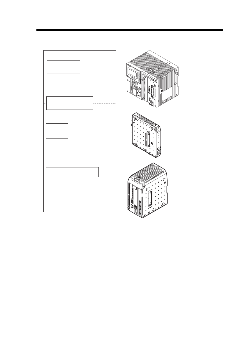
Relevant Manuals
PLC CPU unit
EtherNet/IP unit
CB-EP100 (this unit)
Manuals related
to CPU unit
Manuals related to
EtherNet/IP unit
This
manual
KV-DN20
MS
NS
ON
TERM.
Measuring instrument
Manuals for LJ-V7000 series
Example) LJ-V7000 series
user's manual
The manuals relevant to this document are as follows:
- EtherNet/IP Network Unit CB-EP100 User’s Manual (LJ-V7000 Edition) -
3
Page 6

MEMO
4
- EtherNet/IP Network Unit CB-EP100 User’s Manual (LJ-V7000 Edition) -
Page 7

Manual Organization
1
2
3
4
5
Before Using
Connection and
Configuration
Communicating
with the LJ-V7000
Series
Specifications
Appendix
This chapter provides an overview of the CB-EP100
and describes its part names and functions.
This chapter describes the procedures from
installing the CB-EP100 and measuring instrument
to configuring communication.
This chapter describes the configuration of memory
that communicates with the EtherNet/IP network
unit and a communication timing chart.
This chapter describes the specifications and
dimensions of the CB-EP100.
This chapter provides the parameter list, as well as
troubleshooting instructions.
1
2
3
4
5
- EtherNet/IP Network Unit CB-EP100 User’s Manual (LJ-V7000 Edition) -
5
Page 8

Table of Contents
Safety Information for CB-EP100 ................................................................. 1
General Precautions ......................................................................... 1
Precautions for Use ........................................................................... 1
Precautions on Regulations and Standards ...................................... 2
Relevant Manuals .......................................................................................... 3
Manual Organization ..................................................................................... 5
Table of Contents .......................................................................................... 6
Terms Used in This Document ..................................................................... 8
Chapter 1 Before Using
1-1 CB-EP100 Overview .......................................................................... 1-2
Overview ........................................................................................ 1-2
Connectable measuring instrument ............................................... 1-2
1-2 Checking the Package Contents ..................................................... 1-3
Package Contents .......................................................................... 1-3
1-3 Part Names and Functions ............................................................... 1-4
Chapter 2 Connection and Configuration
2-1 Procedures from Installation before Using the CB-EP100
2-2 Installation and Connection to measuring instrument .................. 2-3
2-3 Wiring ................................................................................................. 2-5
2-4 Configuring Communication with the CB-EP100 ........................... 2-7
2-5 Configuring Communication with the Scanner ............................ 2-10
Chapter 3
3-1 What is EtherNet/IP? ......................................................................... 3-2
3-2 CB-EP100 EtherNet/IP Communication Function .......................... 3-3
3-3 Cyclic communication ...................................................................... 3-5
6
- EtherNet/IP Network Unit CB-EP100 User’s Manual (LJ-V7000 Edition) -
to Configuration ................................................................................. 2-2
Configuration Procedures .............................................................. 2-2
Connecting a communication cable ............................................... 2-5
CB-EP100 Settings ........................................................................ 2-7
Setting the scanner ...................................................................... 2-10
Communicating with the LJ-V7000 Series
What is EtherNet/IP? ...................................................................... 3-2
Overview of Communication Methods ........................................... 3-3
Configuring Cyclic Communication ................................................ 3-6
Actions which can be completed with Cyclic Communication ........ 3-6
Usable Connections .......................................................................3-7
Page 9

Assignment to IN Area (CB-EP100 to Scanner) ............................ 3-8
Assignment to OUT Area (Scanner to CB-EP100) ......................3-20
Communication Methods ............................................................. 3-23
Checking the Device Compatibility ............................................... 3-27
3-4 Message Communication ............................................................... 3-28
Configuring Message Communication ......................................... 3-29
Actions which can be Completed with Message
Communication ............................................................................ 3-29
Objects and Services ................................................................... 3-34
Objects for use with the CB-EP100 .............................................. 3-36
Basic Format and Processing Flow of Message
Communication ............................................................................ 3-37
Reading the CB Object Table ......................................................3-39
CB Object (Class ID:6BH) ............................................................ 3-40
Using CB Object ........................................................................... 3-74
3-5 Communication functions other than EtherNet/IP ....................... 3-87
Chapter 4 Specifications
4-1 Specifications .................................................................................... 4-2
4-2 Data Processing Time ......................................................................4-3
4-3 Dimensions ........................................................................................ 4-4
Chapter 5 Appendix
5-1 Device Profile .................................................................................... 5-2
5-2 Troubleshooting ................................................................................ 5-3
5-3 Default Settings ................................................................................. 5-5
5-4 Configuration Procedure for Control/Compact Logix Series .......5-6
5-5 Objects for use with the CB-EP100 ................................................. 5-8
List of Usable Objects .................................................................... 5-8
Reading Each Object Table ...........................................................5-9
Identity Object (Class ID: 01H) ..................................................... 5-10
Message Router Object (Class ID: 02H) ...................................... 5-13
Assembly Object (Class ID: 04H) ................................................. 5-14
Connection Manager Object (Class ID: 06H) ...............................5-16
TCP/IP Interface Object (Class ID: F5H) ..................................... 5-18
Ethernet Link Object (Class ID: F6H) ........................................... 5-22
5-6 Index ................................................................................................. 5-25
- EtherNet/IP Network Unit CB-EP100 User’s Manual (LJ-V7000 Edition) -
7
Page 10

Terms Used in This Document
This document uses the following terms:
Ter m Description
Scanner The EtherNet/IP scanner device
Adaptor The EtherNet/IP adaptor device
Measuring
instrument
PLC Programmable logic controller
Ladder program A program which controls the PLC
A measuring instrument controller that is connected to an
EtherNet /IP adapter.
8
- EtherNet/IP Network Unit CB-EP100 User’s Manual (LJ-V7000 Edition) -
Page 11

Before Using
This chapter provides an overview of the CB-EP100 and describes
its part names and functions.
1-1 CB-EP100 Overview .......................................... 1-2
1-2 Checking the Package Contents ........................ 1-3
1-3 Part Names and Functions ................................. 1-4
1
- EtherNet/IP Network Unit CB-EP100 User’s Manual (LJ-V7000 Edition) -
1-1
Page 12
1-1
PLC or other host device
(EtherNet/IP unit)
CB-EP100 (this unit)
EtherNet/IP
adaptor
Ethernet
CB-EP100 Overview
1
Overview
Before Using
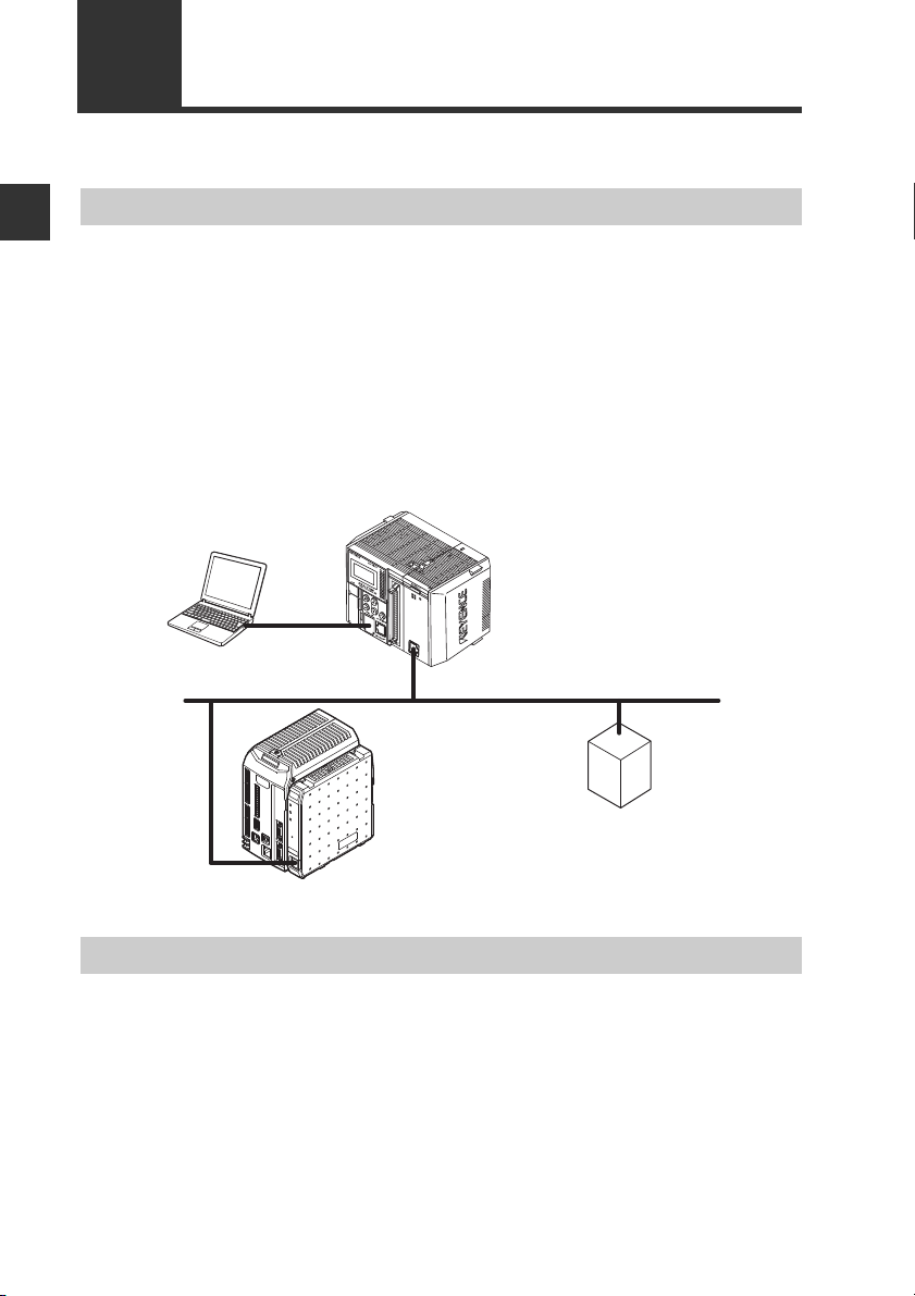
The CB-EP100 operates as an EtherNet/IP communication adaptor. EtherNet/IP
communication enables to output control states, current values and other data of the
CB-EP100 and measuring instrument connected to the CB-EP100 as communication
data to a PLC or other equipment.
The CB-EP100 supports EtherNet/IP cyclic communication (Implicit messaging) and
message communication (Explicit messaging). Cyclic communication enables data
exchange without a ladder program. Message communication enables to acquire
current values from a measuring instrument, reading/writing measuring instrument
settings and send control data to a measuring instrument.
■ System configuration example
Connectable measuring instrument
■ Connectable measuring instrument
The CB-EP100 enables connection of one measuring instrument.
1-2
- EtherNet/IP Network Unit CB-EP100 User’s Manual (LJ-V7000 Edition) -
Page 13
1-2
Before using the CB-EP100, make sure that the following equipment and accessories
are included in the package.
We have thoroughly inspected the package contents before shipment. However, in
the event of defective or broken items, contact your nearest KEYENCE office.
Checking the Package Contents
Package Contents
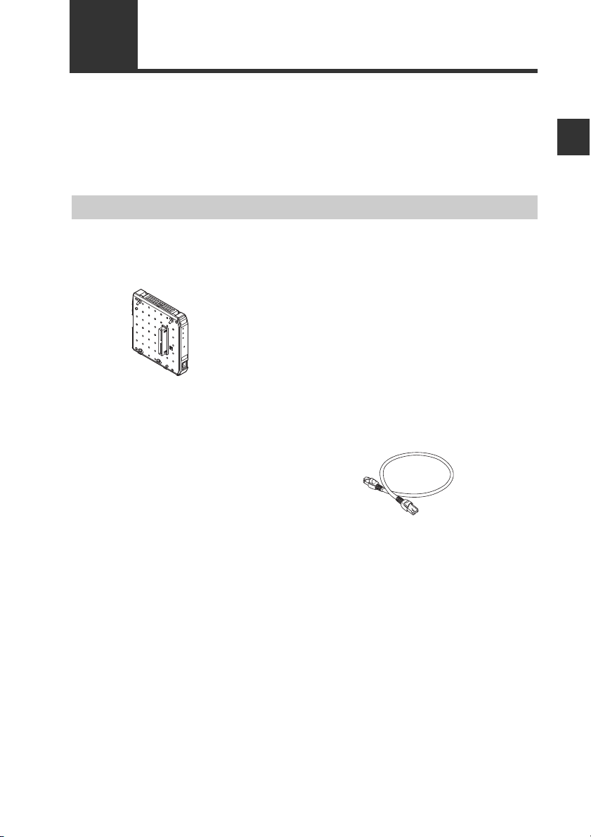
■ Package contents
CB-EP100 main unit x 1
User's Manual (this manual) x 1
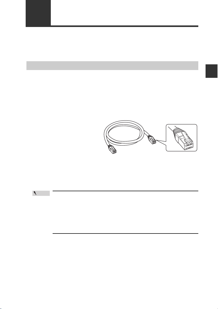
■ List of Optional Parts
• STP (shielded twisted pair) cable
(Category 5e, straight)
- OP-51504 (0.2m)
- OP-51505 (0.5m)
- OP-51506 (1m)
- OP-51507 (3m)
- OP-51508 (5m)
* The working ambient temperature of the above
cables are 0 to 50°C.
1
Before Using
- EtherNet/IP Network Unit CB-EP100 User’s Manual (LJ-V7000 Edition) -
1-3
Page 14
1-3
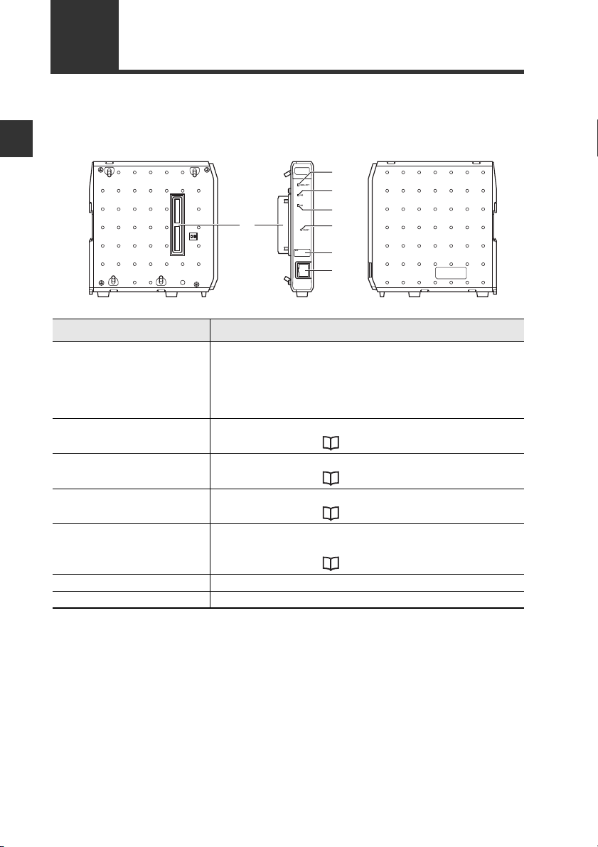
This section describes the part names and functions of the CB-EP100.
Part Names and Functions
1
Right side Left side
Before Using
(1)
Name Description
(1) Connector for
connecting controller
(2) LINK/ACT LED Normal: Green LED lights up or blinks
(3) MS LED Normal: Green LED lights up
(4) NS LED Normal: Green LED lights up or blinks
(5) RESET button When held down for three seconds or longer, the CB-
(6) MAC address MAC address (two lines) for the CB-EP100.
(7) Communication port Connector for the Ethernet cable. (RJ-45 connector)
Connect the controller to this connector.
However, with instrument like the LJ-V7000 series that
use a display output unit, the display output unit should
be connected to the controller and the CB-EP100 should
be connected to the display output unit.
For details, Refer to "Troubleshooting" (Page 5-3).
For details, Refer to "Troubleshooting" (Page 5-3).
For details, Refer to "Troubleshooting" (Page 5-3).
EP100 settings will be reset to the default settings.
For details, Refer to "Default Settings" (Page 5-5).
(2)
(3)
(4)
(5)
(6)
(7)
1-4
- EtherNet/IP Network Unit CB-EP100 User’s Manual (LJ-V7000 Edition) -
Page 15

Connection and Configuration
This chapter describes procedures from installing the CB-EP100
and measuring instrument to configuring communication.
2-1 Procedures from Installation before Using the
CB-EP100 to Configuration................................ 2-2
2-2 Installation and Connection to measuring
instrument........................................................... 2-3
2-3 Wiring ................................................................. 2-5
2-4 Configuring Communication with the CB-EP100..2-7
2-5 Configuring Communication with the Scanner . 2-10
2
- EtherNet/IP Network Unit CB-EP100 User’s Manual (LJ-V7000 Edition) -
2-1
Page 16
2-1
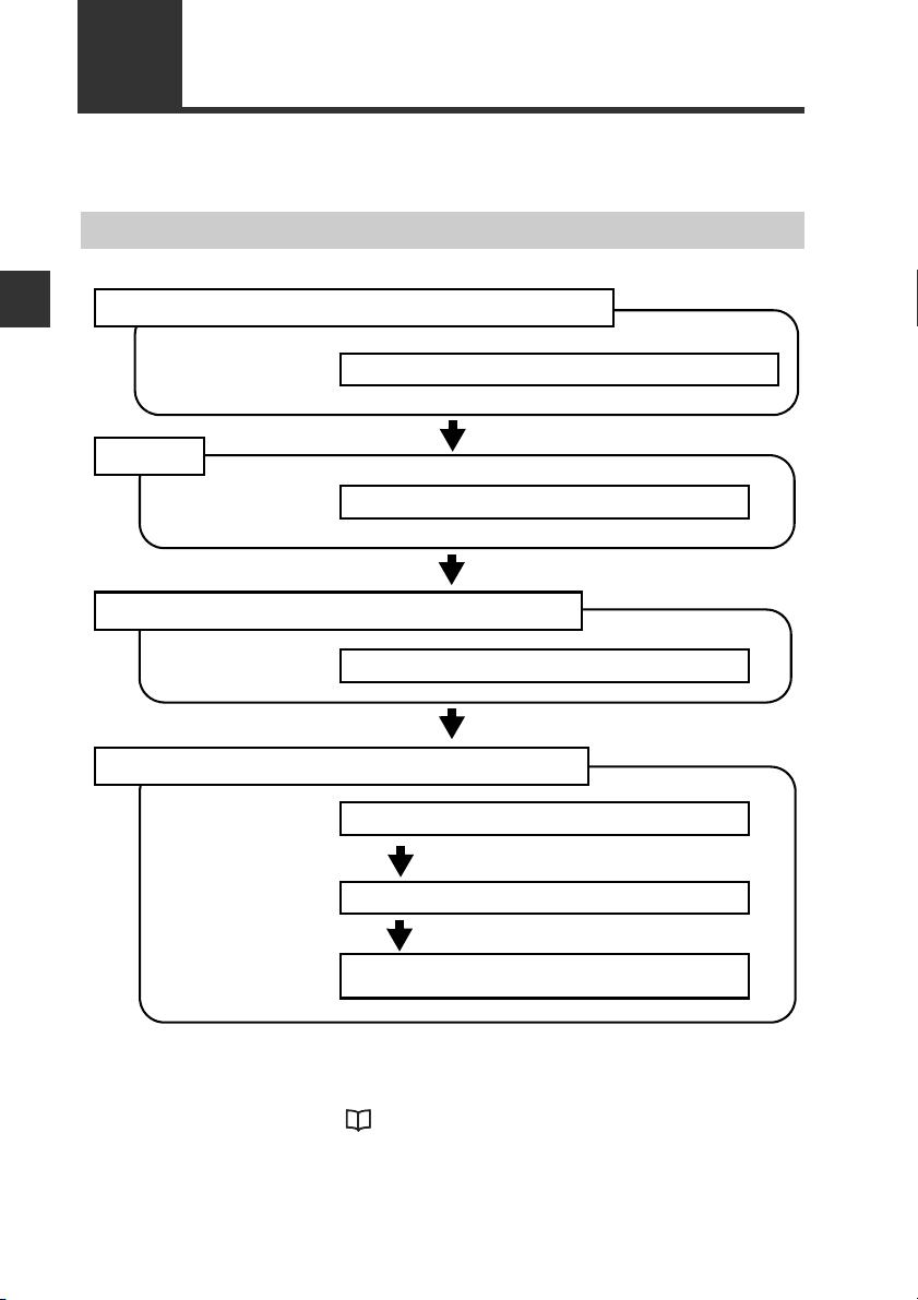
1. Installation and Connection to measuring instrument
Connecting the CB-EP100 to measuring instrument
(Page 2-3)
2. Wiring
3. Configuring Communication with the CB-EP100
4. Configuring Communication with the Scanner
Connecting a communication cable (Page 2-5)
Setting the IP address (Page 2-7)
Setting the IP address (Page 2-10)
Registering the device profile of the CB-EP100
(Page 2-10)
Configuring the Scanner Side
(Refer to each scanner manual.)
This section describes the procedures before you use the CB-EP100.
Procedures from Installation before Using the CB-EP100 to Configuration
Configuration Procedures
2
Connection and Configuration
The above configurations enable communication.
For the outline of scanner side configuration for communication with a Rockwell
Automation scanner, refer to "Configuration Procedure for Control/Compact Logix
Series" (Page 5-6).
2-2
- EtherNet/IP Network Unit CB-EP100 User’s Manual (LJ-V7000 Edition) -
Page 17
2-2
NOTICE
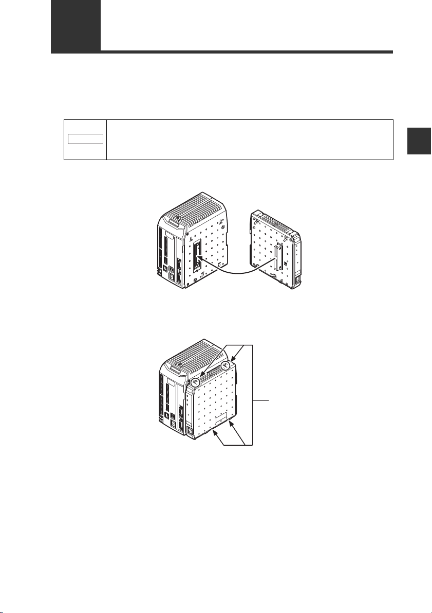
Connecting the CB-EP100 to measuring instrument
EtherNet/IP Network Unit CB-EP100 must be connected to measuring instrument
before it can function.
1
2
Installation and Connection to measuring instrument
Make sure that the measuring instrument are turned off before
connecting the EtherNet/IP Network Unit CB-EP100. Connecting
the CB-EP100 to a measuring instrument that is on could damage it
or the measuring instrument.
Insert the connector after removing the protective cover sticker from the
connector on the side of the measuring instrument.
Tighten the joint screws of the CB-EP100 using a screwdriver.
Tighten the screws to a torque of no more than 0.7N・m.
2
Connection and Configuration
Fix using joint screws
Bottom
- EtherNet/IP Network Unit CB-EP100 User’s Manual (LJ-V7000 Edition) -
2-3
Page 18
2-2 Installation and Connection to measuring instrument
Tab
2
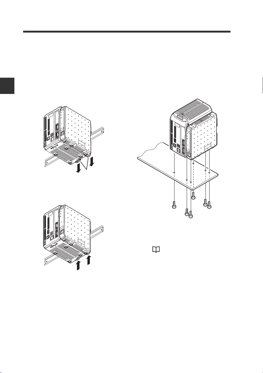
Mounting the controller to a DIN rail
This section explains the procedure for
mounting the controller to a DIN rail.
Pull the tab on the back panel
1
of the controller and the CBEP100, and then attach the
controller and the CB-EP100 to
Connection and Configuration
the DIN rail.
Push in the tab to fix the
2
controller and the CB-EP100 in
place.
Mounting using the bottom panel
This section explains the procedure for
mounting the controller using the
bottom panel.
Fasten the screws into the
1
mounting holes on the bottom
panel.
Six M4 screws (screw depth 6 mm)
For information on mounting
dimension, refer to
"Dimensions" (Page 4-4).
2-4
- EtherNet/IP Network Unit CB-EP100 User’s Manual (LJ-V7000 Edition) -
Page 19
2-3
STP/UTP cable
Point
The CB-EP100 uses the power supplied to measuring instrument, so there is no
power cable wiring. This section describes the wiring of communication cables used
by the CB-EP100.
Wiring
Connecting a communication cable
Use the following procedures to connect the CB-EP100 to the communication cable
required for EtherNet/IP communication.
Usable cable
Usable cables depend on whether the system is configured with 10BASE-T or
100BASE-TX.
Structuring a 10BASE-T system
When the system is configured
with 10BASE-T, use a Category
3 or higher shielded twisted-pair
(STP) cable or an unshielded
twisted-pair (UTP) cable.
Building a 100BASE-TX network or better 5e
Use STP or UTP cable category 5e or better to configure a network using
100BASE-TX. Do not use a Category 3 or Category 4 cable.
2
Connection and Configuration
• Use an STP/UTP straight cable when connecting the CB-EP100 to an
Ethernet switch.
• Use a STP/UTP cross cable when directly connecting the CB-EP100 to
a PC or PLC.
• Do not use the STP/UTP cross cable incorrectly because it is difficult to
distinguish this cable from the STP/UTP straight cable in appearance.
• Use of 1000BASE-T Ethernet cable will not make it possible to configure
a 1000BASE-T network.
- EtherNet/IP Network Unit CB-EP100 User’s Manual (LJ-V7000 Edition) -
2-5
Page 20
2
NOTICE
Point
2-3 Wiring
CB-EP100 connector port
The CB-EP100 connector port accepts an RJ-45 8-pole modular connector (ISO8877
compliant) used with 10BASE-T and 100BASE-TX and complies with the IEEE802.3
Standards.
Precautions for connecting a STP/UTP cable to the CB-EP100 connector port
Take care not to apply a load to the CB-EP100 connector port when connecting the
STP/UTP cable to the CB-EP100.
Connection and Configuration
Connecting the CB-EP100 to EtherNet/IP
The following describes how to connect the CB-EP100 to the RJ-45 connector.
1
2
The cable may be bent and used when installed. Bending the cable
at a sharp angle may cut the wires in the cable or the cable may be
disconnected during use. Install or lay the cable to be used with
attention to the recommended bending radius R of the cable.
Turn off the power supply.
Connect one modular jack of the STP/UTP cable to the 10BASE-T/
100BASE-TX port of the Ethernet switch to be used.
Insert the modular jack until a "click" is heard. The modular jack and connector
will lock.
2-6
・ Keep the length of the STP/UTP cable to be used 100 m or less.
・ Carefully check the shape and type of connector (port) on the
Ethernet switch before connecting the CB-EP100 to the Ethernet
switch.
Connect the modular jack on the other end of the STP/UTP cable to the
3
CB-EP100 connector port.
Insert the jack until a "click" is heard. The modular jack and connector will lock.
- EtherNet/IP Network Unit CB-EP100 User’s Manual (LJ-V7000 Edition) -
Page 21
2-4
This section describes settings for connecting the CB-EP100 to the EtherNet/IP system.
Configuring Communication with the CB-EP100
CB-EP100 Settings
The following describes how to set communication with the CB-EP100.
Setting the IP address
Set the IP address with the CB-EP100 wired and with the power supplied.
By default, the IP address is not set. However, the BOOTP client function can be
used to set the IP address via Ethernet.
The following 2 methods are available for setting the IP address.
• Using the IP address setting tool<IP Setting Tool>.
The <IP Setting Tool> software is included on the CD-ROM supplied with a
measuring instrument.
You can also download it from the Keyence web site (http://www.keyence.com).
Refer to the following setting procedures or the "IP Setting Tool User's Manual".
• Use an IP address setting tool from other sources.
Refer to the manuals provided by the respective sources.
z Using the IP address setting tool
Here briefly describes the procedures for setting the IP address with the IP
address setting tool. For details on how to use the IP address setting tool, refer to
the "IP Setting Tool User's Manual". You can view the "IP Setting Tool User's
Manual" from [Help(H)] of "IP Setting Tool" as the PDF file.
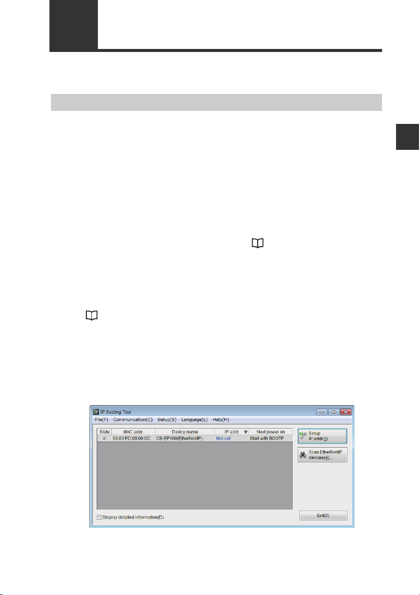
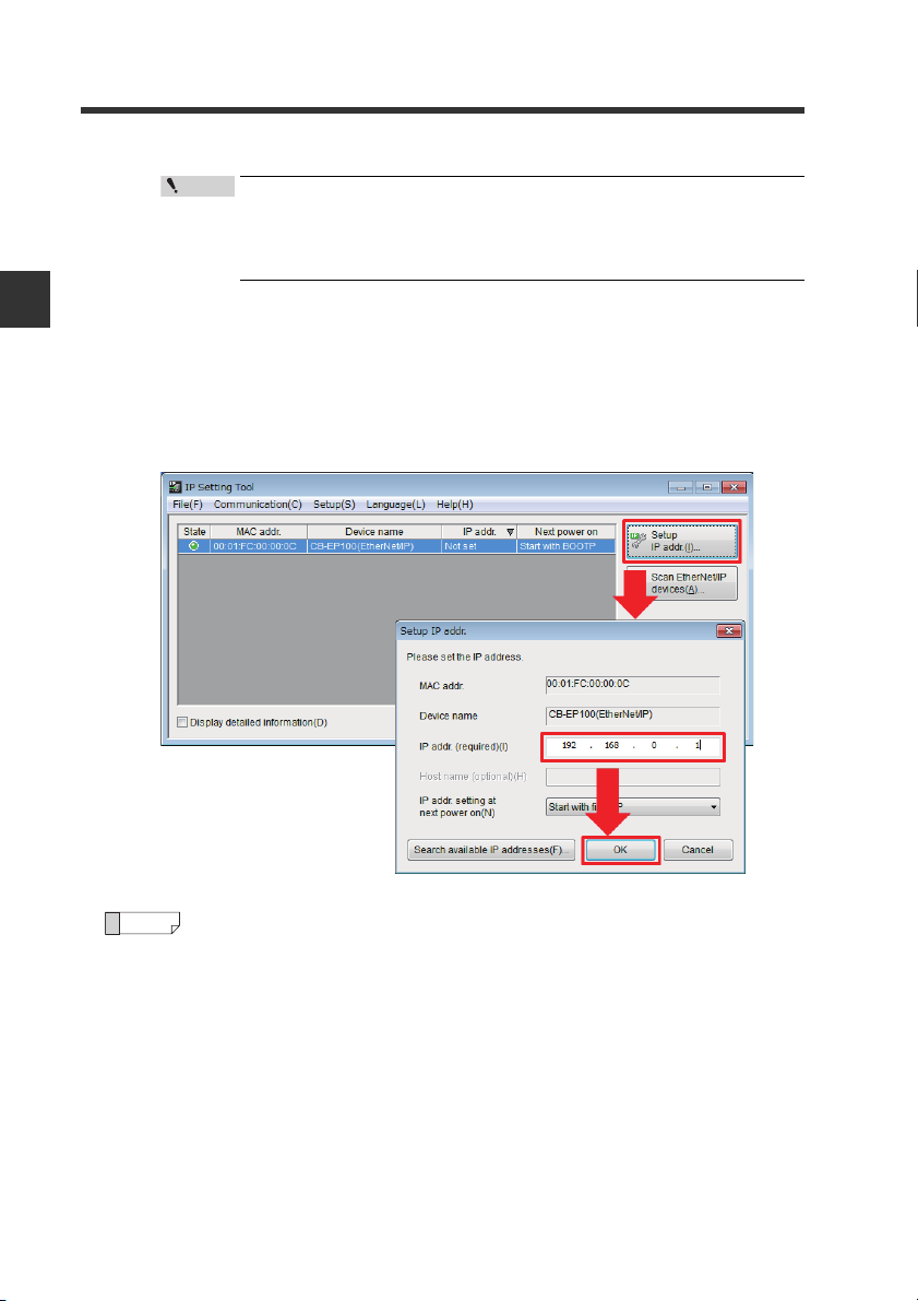
Start the IP Setting Tool.
1
Devices such as the CB-EP100 connected to the network and for which their IP
address is not set will appear.
To display the devices for which their IP address is set, click the [Scan
EtherNet/IP devices (A)] button.
2
Connection and Configuration
- EtherNet/IP Network Unit CB-EP100 User’s Manual (LJ-V7000 Edition) -
2-7
Page 22
2
Point
Reference
2-4 Configuring Communication with the CB-EP100
To display "Not Set" for the IP address, the network status indicator
(NS) must be off (IP address not assigned). To unassign the IP
address, hold down the Reset switch on the CB-EP100 for three
seconds or longer.
Select the device for which to set the IP address and click [Setup IP addr.(I)] to
Connection and Configuration
2
display [Setup IP addr.].
Compare the MAC address to be displayed with the front panel MAC address
on the CB-EP100 and select the device for which to set the IP address.
Set an IP address which is not currently used in "IP addr.(required)(I)" and click
the [OK] button.
2-8
Using the [Search available IP addresses (F)] button enables you to
search for open IP addresses.
- EtherNet/IP Network Unit CB-EP100 User’s Manual (LJ-V7000 Edition) -
Page 23
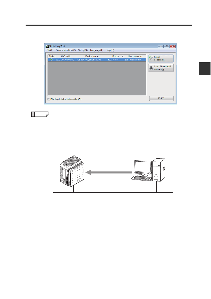
The IP address has now been set.
IP address assignment
BOOTP client
BOOTP server
Via Ethernet
Ethernet
3
2-4 Configuring Communication with the CB-EP100
2
Connection and Configuration
Reference
What is BOOTP?
BOOTP is the abbreviation of BOOT strap Protocol. This protocol is used
by the client device in the TCP/IP network to make the network settings
assigned from the server.
If there is a BOOTP server in the same network as the device running as
the BOOTP client, an IP address is assigned to the device connected as
the BOOTP client.
- EtherNet/IP Network Unit CB-EP100 User’s Manual (LJ-V7000 Edition) -
2-9
Page 24

2
Reference
2-5
This section describes scanner side configuration for connecting the CB-EP100 to the
EtherNet/IP system. When communicating with an Allen-Bradley scanner, also refer to
the "
Configuring Communication with the Scanner
Configuration Procedure for Control/Compact Logix Series
Setting the scanner
Connection and Configuration
Connecting the CB-EP100 to the EtherNet/IP scanner requires the following settings:
Setting the IP address
Set the IP address of the scanner.
Registering the device profile of the CB-EP100
Register the device profile of the adaptor (CB-EP100) to be connected using the
scanner's setting software.
You can register the device profile manually or by reading the EDS (Electronic Data
Sheet) file. You can download the EDS file of the CB-EP100 from the Keyence web
site (http://www.keyence.com).
Configuring communication with the CB-EP100
The CB-EP100 uses EtherNet/IP cyclic communication or message communication
to communicate with the scanner.
z Cyclic communication (Implicit messaging)
This function sends and receives data at a set RPI (Requested Packet Interval).
Selecting the communication method called "connection" and assigning the
devices to be sent and received on the scanner side enables the CB-EP100 to
communicate with the scanner without creating a ladder program.
z Message communication (Explicit messaging)
This function is used to send and receive data which does not need to be timed.
Use this function when changing the measuring instrument settings or when
performing EtherNet/IP communication with the scanner (e.g., Rockwell
Automation MicroLogix Series) that does not support cyclic communication.
This function uses a ladder program to create a message on the scanner side for
communication.
" (Page 5-6).
For more information on setting each communication method, refer to the chapters
titled "Communicating with the LJ-V7000 series" ( Page 3-1) as well as the manuals
enclosed with each scanner.
This manual explains only the EtherNet/IP scanner functions and settings
required for communication with the CB-EP100. For details on the
functions and settings between the EtherNet/IP scanner and CPU unit,
refer to the manuals enclosed with the scanner and CPU unit.
2-10
- EtherNet/IP Network Unit CB-EP100 User’s Manual (LJ-V7000 Edition) -
Page 25

Communicating with
the LJ-V7000 Series
This chapter describes the configuration of memory linked with the
EtherNet/IP network unit and a communication timing chart.
It also describes functions that can use communication
methods other than EtherNet/IP communications.
3-1 What is EtherNet/IP?.......................................... 3-2
3-2 CB-EP100 EtherNet/IP Communication Function ...3-3
3-3 Cyclic communication......................................... 3-5
3-4 Message Communication ................................. 3-28
Communication functions other than EtherNet/IP .....
3-5
3-87
3
- EtherNet/IP Network Unit CB-EP100 User’s Manual (LJ-V7000 Edition) -
3-1
Page 26

3
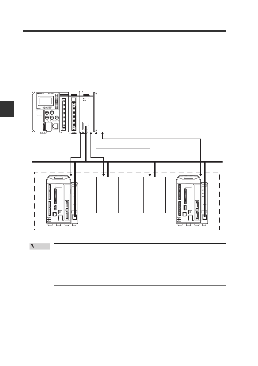
Scanner
Adaptor Adaptor Adaptor
High speed
(Communication cycle: 10 ms)
Regular speed
(Communication
cycle: 100 ms)
Low speed (Communication cycle: 1000 ms)
3-1
What is EtherNet/IP?
What is EtherNet/IP?
EtherNet/IP is an industrial communication network with open specifications. The
specifications are managed by ODVA (Open DeviceNet Vendor Association, Inc.).
Industrial protocol has been combined with the Ethernet and standardized as EtherNet/IP (Industrial Protocol).
Communication is realized by combining the protocols known as Common Industrial
Protocol (CIP) with TCP/IP and Ethernet. This allows regular Ethernet to be used
together with the network.
Communicating with the LJ-V7000 Series
Before starting EtherNet/IP communication, one of the devices must open a
communication line called a "connection" with the other device. The side which
opens the connection is called the "scanner", and the side to be opened is called the
"adaptor". (The CB-EP100 is an adaptor.)
EtherNet/IP includes cyclic communication (Implicit messaging) which sends and
receives data periodically. Message communication (Explicit messaging) which
sends and receives commands and responses at a desired timing.
Cyclic communication enables you to set RPI (Requested Packet Interval) according
to the priority of the data to be exchanged, allowing the entire communication load to
be adjusted for data exchange.
Message communication enables you to exchange the required commands and
responses at the required timing. Message communication is used for applications
which do not require the punctuality of cyclic communication, such as reading and
writing adaptor settings.
3-2
- EtherNet/IP Network Unit CB-EP100 User’s Manual (LJ-V7000 Edition) -
Page 27

3-2
CB-EP100 EtherNet/IP Communication Function
This section describes the EtherNet/IP functions supported by the CB-EP100.
The CB-EP100 functions as an EtherNet/IP adaptor, and supports both cyclic and
message EtherNet/IP communications.
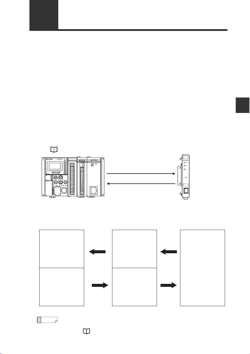
EtherNet/IP scanner CB-EP100
IN area
OUT area
IN area
Cyclic communication
Control status
Current value
Error information
Cyclic communication
Control data
Message communication
Measuring instrument
Output
Judgement results
Error information
Control input
Setting value
3
Communicating with the LJ-V7000 Series
OUT area
Direct read/write of various parameters
Overview of Communication Methods
The EtherNet/IP scanner can use the following functions:
Communication method
Available functions
Clearing system errors
Reading system status
Reading error codes
Reading OUT measurement values
Reading judgment results
Reading OUT measurement value
status
Reading measuring instrument
control status
Inputing control data
Reading current program number
Switching the programs
Reading number of storage points
Writing/reading OUT measurement
setting
Reading profile data
Reading auto-zero reference value
Writing/reading controller device
name
Reading controller/sensor head type
Cyclic communication
(Page 3-5)
{{
X {
Message Communication
(Page 3-28)
- EtherNet/IP Network Unit CB-EP100 User’s Manual (LJ-V7000 Edition) -
3-3
Page 28
3
PLC
EtherNet/IP scanner
RPI=3 (ms)*
RPI=0.5 (ms)*
RPI=5 (ms)*
RPI=10 (ms)*
Various EtherNet/IP adaptors
Ethernet
* RPI (Requested Packet Interval) can be set
individually for each connection.
Point
3-2 CB-EP100 EtherNet/IP Communication Function
Cyclic communication
This function sends and receives data between the scanner and CB-EP100 at the set
RPI (Requested Packet Interval). Measurement values, judgment results and error
status of measuring instrument can be transferred without the use of a ladder
program.
Communicating with the LJ-V7000 Series
Configurations such as RPI and data size for cyclic communication are set
on the scanner side.
In a network which has many connected devices, including EtherNet/IP
devices, a delay or packet loss could occur if a large load is constantly or
temporarily applied on the network. Verify the settings carefully before
operation.
Message communication
Message communication can be used for applications which do not require a
punctuality like cyclic communication.
Various functions can be processed via message communication,such as reading or
writing data which can be exchanged with cyclic communication, reading measuring
instrument profiles, reading and writing measurement settings, and execute other
functions unique to measuring instrument.
3-4
- EtherNet/IP Network Unit CB-EP100 User’s Manual (LJ-V7000 Edition) -
Page 29
3-3
(1) Request connection open
(3) Open connection
(2) Check
compatibility
Cyclic communication
This section describes the cyclic communication functions and how to use them.
What is cyclic communication?
Cyclic communication is a function that exchanges data with the EtherNet/IP device
in a cyclic manner (at a set cycle).
In cyclic communication, data can be exchanged when one device successfully
opens a logical communication line called a "connection" with the other device.
The side which opens the connection is called the scanner, and the side to be
opened is called the adaptor. (The CB-EP100 is an adaptor.)
Cyclic communication is started in the following procedures:
(1) The scanner requests the adaptor to open the connection.
(2) The adaptor side checks compatibility.
(3) If no error occurs as a result the compatibility check, the adaptor opens the
connection.
(* If an error is found during the compatibility check, the adaptor does not open
the connection.)
"Checking the Device Compatibility" (Page 3-27)
Data is exchanged between the EtherNet/IP scanner, CB-EP100 and each
measuring instrument as follows:
EtherNet/IP scanner CB-EP100 Measuring instrument
Output data
IN area
OUT area
Cyclic
communication
Cyclic
communication
Data reflected in the
scanner
Input data
The data output from the
scanner is stored by the
CB-EP100.
Data in
measuring
instrument is
refreshed
Data in
measuring
instrument is
refreshed
3
Communicating with the LJ-V7000 Series
Reference
To carry out EtherNet/IP communication with a scanner which does not
support cyclic communication (Rockwell Automation MicroLogix Series,
etc.), use "Message Communication" (Page 3-28).
- EtherNet/IP Network Unit CB-EP100 User’s Manual (LJ-V7000 Edition) -
3-5
Page 30

3-3 Cyclic communication
Configuring Cyclic Communication
The following settings are required to execute cyclic communication with the CBEP100.
[CB-EP100]
The CB-EP100 does not require any setting.
3
Communicating with the LJ-V7000 Series
[Scanner]
(1) Set the connection to be used.
(2) Set the devices used in cyclic communication.
Refer to the scanner manual for details on how to make the above settings.
(* No ladder program is required when cyclic communication is used.)
Actions which can be completed with Cyclic Communication
Cyclic communication can use the following functions:
(1) Clearing system errors
(2) Reading system status
(3) Reading error codes
(4) Reading OUT measurement values
(5) Reading judgment results
(6) Reading OUT measurement value status
(7) Reading measuring instrument control status
(8) Inputing control data
(9) Reading current program number
(10) Switching the programs
(11) Reading number of storage points
3-6
- EtherNet/IP Network Unit CB-EP100 User’s Manual (LJ-V7000 Edition) -
Page 31

3-3 Cyclic communication
Usable Connections
EtherNet/IP requires that a connection must be opened from the scanner when cyclic
communication is started. There are various types of connections, and the type
usable by each device is defined in the EDS file.
The CB-EP100 can use the following connections:
Connection
No
Name
Monitor Data And
1
Control Data
Monitor Data
2
(Input Only)
Reference
Input/Output
CB-EP100 to
scanner
Scanner to
CB-EP100
CB-EP100 to
scanner
Scanner to
CB-EP100
・ Each connection's trigger timing is executed cyclically. The connection
type supports both point-to-point and multicast.
・ The details of each application type are as follows:
Exclusive Owner:
This connection allows simultaneous setting of both data
transmission from the scanner to the CB-EP100 and data
transmission from the CB-EP100 to the scanner. This setting is
made not only when the scanner monitors the adapter (CBEP100) data, but also when it issues control inputs and rewrites
the settings. etc. Multiple "Exclusive Owner" connections cannot
be opened to one adaptor (CB-EP100).
Input Only:
This connection allows only data transmission from the CBEP100 to the scanner. This setting is made when the scanner
only monitors adaptor (CB-EP100) data. Multiple scanners can
open an "Input Only" connection simultaneously to one adaptor
(CB-EP100).
(* To simultaneously open connections from multiple scanners,
set Connection Type to Multicast, and also set the same RPI
setting on each scanner.)
Assembly
Instance
64H (100) 312
65H (101) 124
64H (100) 312
FEH (254) 0
Size
(Byte)
RPI Range
(in 0.5 ms)
0.5 ms to
10000 ms
0.5 ms to
10000 ms
Application
Ty pe
Exclusive
Owner
Input Only
3
Communicating with the LJ-V7000 Series
- EtherNet/IP Network Unit CB-EP100 User’s Manual (LJ-V7000 Edition) -
3-7
Page 32

3
CB-EP100 data
Scanner IN area
Address 0
Address 1
Address 311
Monitor Data
(Assembly Instance: 100)
1-byte (8-bit) data
Reference
16-bit data
Address 40 to 41
16-bit data
Address 42 to 43
12H 34H
56H 78H
High-order byte Low-order byte
High-order byte Low-order byte
56H
43
78H4212H4134H
40
32-bit data
Address 48 to 51
12H
51
34H5056H4978H
48
12H 34H 56H 78H
3-3 Cyclic communication
Assignment to IN Area (CB-EP100 to Scanner)
The data from the CB-EP100 is assigned to the EtherNet/IP scanner's IN area.
Communicating with the LJ-V7000 Series
The data such as 16-bit data extending over multiple bytes is stored into
an area which starts with an even address in order from the lowest-order
byte.
Example)
3-8
- EtherNet/IP Network Unit CB-EP100 User’s Manual (LJ-V7000 Edition) -
Page 33

3-3 Cyclic communication
Monitor Data (156 Words (312 Bytes)) Assembly Instance (Instance ID): 64H
This is the device map for the monitor data to be assigned to the IN area.
For details on each parameter, refer to "Parameter List" (Page 3-15).
Address
Name
System
Status
Measuring
instrument
status
Vali d
status
Judgment
standby
status
Alarm
status
Reserved
for system
Judgment
output (HI)
Judgment
output
(LO)
Judgment
output
(GO)
Reserved
for system
Timing
status
bit7 bit6 bit5 bit4 bit3 bit2 bit1 bit0
(Byte)
0 Reserved for system
1 Reserved for system Saving
2 Reserved for system REMOTE
3 Reserved for system
10
15
16
17
18
19
20
21
22
33
34
35
4
5
6
7
8
9
-
-
Valid status
Valid status
Judgment
standby
Judgment
standby
Valid status
OUT8
Valid status
OUT16
Judgment
status
OUT8
Judgment
status
OUT16
Alarm
status
OUT8
Alarm
status
OUT16
HI
OUT8HIOUT7HIOUT6HIOUT5HIOUT4HIOUT3HIOUT2HIOUT1
HI
OUT16HIOUT15HIOUT14HIOUT13HIOUT12HIOUT11HIOUT10HIOUT9
LO
OUT8LOOUT7LOOUT6LOOUT5LOOUT4LOOUT3LOOUT2LOOUT1
LO
OUT16LOOUT15LOOUT14LOOUT13LOOUT12LOOUT11LOOUT10LOOUT9
GO
OUT8GOOUT7GOOUT6GOOUT5GOOUT4GOOUT3GOOUT2GOOUT1
GO
OUT16GOOUT15GOOUT14GOOUT13GOOUT12GOOUT11GOOUT10GOOUT9
Timing
status
OUT8
Timing
status
OUT16
OUT7
OUT15
standby
status
OUT7
standby
status
OUT15
Alarm
status
OUT7
Alarm
status
OUT15
Timing
status
OUT7
Timing
status
OUT15
Valid status
OUT6
Valid status
OUT14
Judgment
standby
status
OUT6
Judgment
standby
status
OUT14
Alarm
status
OUT6
Alarm
status
OUT14
Timing
status
OUT6
Timing
status
OUT14
Valid status
Valid status
OUT13
Judgment
standby
Judgment
standby
OUT13
OUT13
Reserved for system
Reserved for system
Timing
Timing
OUT13
OUT5
status
OUT5
status
Alarm
status
OUT5
Alarm
status
status
OUT5
status
Valid status
OUT4
Valid status
OUT12
Judgment
standby
status
OUT4
Judgment
standby
status
OUT12
Alarm
status
OUT4
Alarm
status
OUT12
Timing
status
OUT4
Timing
status
OUT12
Started upCB-EP100
Error Status
Reserved
for system
Valid status
Valid status
Judgment
standby
Judgment
standby
OUT3
OUT11
status
OUT3
status
OUT11
Alarm
status
OUT3
Alarm
status
OUT11
Timing
status
OUT3
Timing
status
OUT11
Valid status
OUT2
Valid status
OUT10
Judgment
standby
status
OUT2
Judgment
standby
status
OUT10
Alarm
status
OUT2
Alarm
status
OUT10
Timing
status
OUT2
Timing
status
OUT10
Error Status
LJ-V
Error status
LASER_OFF
MEMORY
_FULL
Valid status
OUT1
Valid status
OUT9
Judgment
standby
status
OUT1
Judgment
standby
status
OUT9
Alarm
status
OUT1
Alarm
status
OUT9
Timing
status
OUT1
Timing
status
OUT9
3
Communicating with the LJ-V7000 Series
- EtherNet/IP Network Unit CB-EP100 User’s Manual (LJ-V7000 Edition) -
3-9
Page 34

3-3 Cyclic communication
3
Communicating with the LJ-V7000 Series
Name
Auto-zero
status
Reserved
for system
Timing
completion
Auto-zero
completion
Reset
completion
External
input com-
pletion
Reserved
for system
Timing
failure
Auto-zero
failure
Address
bit7 bit6 bit5 bit4 bit3 bit2 bit1 bit0
(Byte)
Auto-zero
36
Auto-zero
37
38
-
45
46
completion
47
completion
Auto-zero
48
completion
Auto-zero
49
completion
50
completion
51
completion
52 Reserved for system
53 Reserved for system
54
-
61
62
63
Auto-zero
64
Auto-zero
65
status
OUT8
status
OUT16
Timing
OUT8
Timing
OUT16
OUT8
OUT16
Reset
OUT8
Reset
OUT16
Timing
failure
OUT8
Timing
failure
OUT16
failure
OUT8
failure
OUT16
Auto-zero
status
OUT7
Auto-zero
status
OUT15
Timing
completion
OUT7
Timing
completion
OUT15
Auto-zero
completion
OUT7
Auto-zero
completion
OUT15
Reset
completion
OUT7
Reset
completion
OUT15
Timing
failure
OUT7
Timing
failure
OUT15
Auto-zero
failure
OUT7
Auto-zero
failure
OUT15
Auto-zero
status
OUT6
Auto-zero
status
OUT14
Timing
completion
OUT6
Timing
completion
OUT14
Auto-zero
completion
OUT6
Auto-zero
completion
OUT14
Reset
completion
OUT6
Reset
completion
OUT14
Timing
failure
OUT6
Timing
failure
OUT14
Auto-zero
failure
OUT6
Auto-zero
failure
OUT14
Auto-zero
Auto-zero
Reserved for system
completion
completion
Auto-zero
completion
Auto-zero
completion
completion
completion
stop com-
Reserved for system
Auto-zero
Auto-zero
status
OUT5
status
OUT13
Timing
OUT5
Timing
OUT13
OUT5
OUT13
Reset
OUT5
Reset
OUT13
Storage
pletion
Timing
failure
OUT5
Timing
failure
OUT13
failure
OUT5
failure
OUT13
Auto-zero
status
OUT4
Auto-zero
status
OUT12
Timing
completion
OUT4
Timing
completion
OUT12
Auto-zero
completion
OUT4
Auto-zero
completion
OUT12
Reset
completion
OUT4
Reset
completion
OUT12
Storage
start com-
pletion
Timing
failure
OUT4
Timing
failure
OUT12
Auto-zero
failure
OUT4
Auto-zero
failure
OUT12
Auto-zero
status
OUT3
Auto-zero
status
OUT11
Timing
completion
OUT3
Timing
completion
OUT11
Auto-zero
completion
OUT3
Auto-zero
completion
OUT11
Reset
completion
OUT3
Reset
completion
OUT11
Batch end
completion
Timing
failure
OUT3
Timing
failure
OUT11
Auto-zero
failure
OUT3
Auto-zero
failure
OUT11
Auto-zero
status
OUT2
Auto-zero
status
OUT10
Timing
completion
OUT2
Timing
completion
OUT10
Auto-zero
completion
OUT2
Auto-zero
completion
OUT10
Reset
completion
OUT2
Reset
completion
OUT10
Batch start
completion
Memory clear
completio n
Timing
failure
OUT2
Timing
failure
OUT10
Auto-zero
failure
OUT2
Auto-zero
failure
OUT10
Auto-zero
status
OUT1
Auto-zero
status
OUT9
Timing
completion
OUT1
Timing
completion
OUT9
Auto-zero
completion
OUT1
Auto-zero
completion
OUT9
Reset
completion
OUT1
Reset
completion
OUT9
Tri g ge r
completion
Error clear
completion
Timing
failure
OUT1
Timing
failure
OUT9
Auto-zero
failure
OUT1
Auto-zero
failure
OUT9
3-10
- EtherNet/IP Network Unit CB-EP100 User’s Manual (LJ-V7000 Edition) -
Page 35

Name
Reset
failure
External
input
failed
Reserved
for system
Program
switch
Reserved
for system
Error
code
Reserved
for system
Current
program
number
Reserved
for system
3-3 Cyclic communication
Address
bit7 bit6 bit5 bit4 bit3 bit2 bit1 bit0
(Byte)
Reset
66
failure
OUT8
Reset
67
failure
OUT16
68 Reserved for system
69 Reserved for system
70
-
75
76 Reserved for system
77 Reserved for system
78
-
83
84
85
86
-
95
96
-
99
100
-
103
Reset
failure
OUT7
Reset
failure
OUT15
Reset
failure
OUT6
Reset
failure
OUT14
Storage
Reserved for system
Reserved for system
Reserved for system
Current program number
Reserved for system
Reset
failure
OUT5
Reset
failure
OUT13
stop
failure
Error code
Reset
failure
OUT4
Reset
failure
OUT12
Storage
start
failure
Reset
failure
OUT3
Reset
failure
OUT11
Batch
end
failure
Reset
failure
OUT2
Reset
failure
OUT10
Batch
start
failure
Memory
clear
failure
Program
switch
failure
Reset
failure
OUT1
Reset
failure
OUT9
Trigger
failure
Error
clear
failure
Program
switch
completion
3
Communicating with the LJ-V7000 Series
- EtherNet/IP Network Unit CB-EP100 User’s Manual (LJ-V7000 Edition) -
3-11
Page 36

3-3 Cyclic communication
3
Communicating with the LJ-V7000 Series
Name
OUT
measure-
ment
value
Address
bit7 bit6 bit5 bit4 bit3 bit2 bit1 bit0
(Byte)
104
107
108
111
112
115
116
119
120
123
124
127
128
131
132
135
136
139
140
143
144
147
148
151
152
155
156
159
160
163
164
167
-
-
-
-
-
-
-
-
-
-
-
-
-
-
-
-
Measurement value
OUT1
Measurement value
OUT2
Measurement value
OUT3
Measurement value
OUT4
Measurement value
OUT5
Measurement value
OUT6
Measurement value
OUT7
Measurement value
OUT8
Measurement value
OUT9
Measurement value
OUT10
Measurement value
OUT11
Measurement value
OUT12
Measurement value
OUT13
Measurement value
OUT14
Measurement value
OUT15
Measurement value
OUT16
3-12
- EtherNet/IP Network Unit CB-EP100 User’s Manual (LJ-V7000 Edition) -
Page 37

3-3 Cyclic communication
Address
Name
OUT
measure-
ment
value
Update
count
OUT
measure-
ment
value
display
unit
bit7 bit6 bit5 bit4 bit3 bit2 bit1 bit0
(Byte)
168
171
172
175
176
179
180
183
184
187
188
191
192
195
196
199
200
203
204
207
208
211
212
215
216
219
220
223
224
227
228
231
232
235
236
239
240
243
244
247
-
-
-
-
-
-
-
-
-
-
-
-
-
-
-
-
-
-
-
-
OUT measurement value update count
OUT measurement value update count
OUT measurement value update count
OUT measurement value update count
OUT measurement value update count
OUT measurement value update count
OUT measurement value update count
OUT measurement value update count
OUT measurement value update count
OUT measurement value update count
OUT measurement value update count
OUT measurement value update count
OUT measurement value update count
OUT measurement value update count
OUT measurement value update count
OUT measurement value update count
OUT measurement value display unit
OUT measurement value display unit
OUT measurement value display unit
OUT measurement value display unit
OUT1
OUT2
OUT3
OUT4
OUT5
OUT6
OUT7
OUT8
OUT9
OUT10
OUT11
OUT12
OUT13
OUT14
OUT15
OUT16
OUT1
OUT2
OUT3
OUT4
- EtherNet/IP Network Unit CB-EP100 User’s Manual (LJ-V7000 Edition) -
3
Communicating with the LJ-V7000 Series
3-13
Page 38

3-3 Cyclic communication
3
Communicating with the LJ-V7000 Series
Name
OUT
measure-
ment
value
display
unit
Number of
storage
data points
Reserved
for system
Address
bit7 bit6 bit5 bit4 bit3 bit2 bit1 bit0
(Byte)
248
251
252
255
256
259
260
263
264
267
268
271
272
275
276
279
280
283
284
287
288
291
292
295
296
299
300
311
-
-
-
-
-
-
-
-
-
-
-
-
-
-
OUT measurement value display unit
OUT measurement value display unit
OUT measurement value display unit
OUT measurement value display unit
OUT measurement value display unit
OUT measurement value display unit
OUT measurement value display unit
OUT measurement value display unit
OUT measurement value display unit
OUT measurement value display unit
OUT measurement value display unit
OUT measurement value display unit
Number of storage data points
OUT5
OUT6
OUT7
OUT8
OUT9
OUT10
OUT11
OUT12
OUT13
OUT14
OUT15
OUT16
Reserved for system
3-14
- EtherNet/IP Network Unit CB-EP100 User’s Manual (LJ-V7000 Edition) -
Page 39

Parameter List
Item Description
The error status of the CB-EP100 or measuring instrument errors are output.
Error Status
CB-EP100
Error Status
Started up
LJ-V
Error status
Saving
Measuring
instrument status
Valid status OUTn
(n: 1 - 16)
Judgment standby
status OUTn
(n: 1 - 16)
Alarm status OUTn
(n: 1 - 16)
When ON, a value is stored in "Error code." When OFF, 0 is stored in "Error
code."
ON: An error occurred in the CB-EP100 or in the connected measuring instrument.
OFF: No error occurred in the CB-EP100 or in the connected measuring instrument.
The error status of the CB-EP100 is output.
ON: An error occurred.
OFF: No error occurred.
Indicates that the CB-EP100 and the measuring instrument have started up and
that cyclic communication data and message communication data can be
normally sent and received.
* Until this bit goes on, data received via cyclic communication is an "initial
value."
ON: Startup preparations are completed.
OFF: Startup preparations are not completed.
The error status of the measuring instrument is output.
ON: An error occurred.
OFF: No error occurred.
Indicates whether a measuring instrument is accessing the save area (and
setting data is being saved).
Caution: The setting data may become corrupted if the power is turned off
during saving or immediately after the completion of saving.
ON: The save area is being accessed.
OFF: The save area is not being accessed (saving completed).
Outputs each control signal status (LASER_OFF, REMOTE, MEMORY_FULL) for
measuring instrument.
ON: Control status of targeted measuring instrument is ON.
OFF: Control status of targeted measuring instrument is OFF.
0 is stored in this bit when each OUT measurement value is in judgment
standby status or alarm status. When this bit is 0, each OUT measurement
value and judgment output is valid.
ON: The measurement value is valid
OFF: The measurement value is invalid (in judgment standby status or alarm
status).
This bit becomes 1 when each OUT measurement value is in judgment standby
status.
Judgment standby status indicates any of the following.
• The measuring instrument has just been started up
• Settings in the measuring instrument have just been changed
• Processing by reset input has just been performed
• Programs have just been changed
• Reset measurement by REMOTE/LASER_OFF input has just been
performed
ON: The judgment value is in judgment standby status
OFF: The judgment value is not in judgment standby status
This bit becomes 1 when an OUT measurement value is in alarm status.
An alarm indicates any of the following.
• The measurement target is not in the measuring range.
• The measurement target does not give off enough light.
• Position correction has not been properly set.
• Measuring mode has not been properly set.
When there is an alarm status, both HI and LO become 1 in the judgment
results of the corresponding OUT.
ON: The measurement value indicates an alarm status.
OFF: The measurement value does not indicate and alarm status.?
3-3 Cyclic communication
3
Communicating with the LJ-V7000 Series
- EtherNet/IP Network Unit CB-EP100 User’s Manual (LJ-V7000 Edition) -
3-15
Page 40

3
3-3 Cyclic communication
Item Description
Judgment output
(HI) OUTn
(n:1 - 16)
Judgment output
(LO) OUTn
(n:1 - 16)
Judgment output
(GO) OUTn
(n:1 - 16)
Timing status
Communicating with the LJ-V7000 Series
OUTn
(n: 1 - 16)
Auto-zero status
OUTn
(n: 1 - 16)
Timing completion
OUTn (n: 1 - 16)
Auto-zero
completion
OUTn (n: 1 - 16)
Reset completion
OUTn (n: 1 - 16)
Trigger completion
Batch start
completion
Batch end
completion
Storage start
completion
Storage stop
mp
letion
co
Error clear
completion
Indicates judgment output status of each OUT measurement value.
1 is stored in this bit when judgment output status is HI.
ON: Judgment output is HI.
OFF: Judgment output is not HI.
Indicates judgment output status of each OUT measurement value.
1 is stored in this bit when judgment output status is LO.
ON: Judgment output is LO.
OFF: Judgment output is not LO.
Indicates judgment output status of each OUT measurement value.
1 is stored in this bit when judgment output status is GO.
ON: Judgment output is GO.
OFF: Judgment output is not GO.
Outputs the timing status for each OUT measurement value.
ON: Timing is ON
OFF: Timing is OFF
Outputs the auto-zero status for each OUT measurement value.
ON: Auto-zero is ON
OFF: Auto-zero is OFF
Indicates whether the timing input request for measurement values has been
completed (when successful).
ON: Timing input request has been completed (when successful)
OFF: Timing input request has not been completed (when not successful)
Indicates whether the auto-zero input request for OUT measurement values has
been completed (when successful).
ON: Auto-zero input request has been completed (when successful)
OFF: Auto-zero input request has not been completed (when not successful)
Indicates whether the reset input request for OUT measurement values has
been completed (when successful).
ON: Reset input request has been completed (when successful)
OFF: Reset input request has not been completed (when not successful)
Indicates whether the external trigger request has been completed (when
successful).
ON: External trigger request has been completed (when successful)
OFF: External trigger request has not been completed (when not successful)
Indicates whether the batch start request has been completed (when
successful).
ON: Batch start request has been completed (when successful)
OFF: Batch start request has not been completed (when successful)
Indicates whether the batch end request has been completed (when
successful).
ON: Batch end request has been completed (when successful)
OFF: Batch end request has not been completed (when not successful)
Indicates whether the storage start request has been completed (when
successful).
ON: Storage start request has been completed (when successful)
OFF: Storage start request has not been completed (when not successful)
Indicates whether the storage end request has been completed (when
successful).
ON: Storage end request has been completed (when successful)
OFF: Storage end request has not been completed (when not successful)
Indicates whether the error clear request has been completed (when
successful).
ON: Error clear request has been completed (when successful)
OFF: Error clear request has not been completed (when not successful)
3-16
- EtherNet/IP Network Unit CB-EP100 User’s Manual (LJ-V7000 Edition) -
Page 41

Item Description
Memory clear
completion
Timing failure
OUTn (n: 1 - 16)
Auto-zero failure
OUTn (n: 1 - 16)
Reset failure
OUTn (n: 1 - 16)
Trigger failure
Batch start failure
Batch end failure
Storage start
failure.
Storage stop
completion
Error clear failure
Memory clear
failure
Program switch
completion
Program switch
failure
Error code
Current program
number
Indicates whether the memory clear request has been completed (when
successful).
ON: Memory clear request has been completed (when successful)
OFF: Memory clear request has not been completed (when not successful)
Indicates whether the timing input request for measurement values has failed.
ON: Timing input request has failed
OFF: Timing input request has not failed
Indicates whether the auto-zero input request for OUT measurement values has
failed.
ON: Auto-zero input request has failed
OFF: Auto-zero input request has failed
Indicates whether the reset input request for OUT measurement values has
failed.
ON: Reset input request has failed.
OFF: Reset input request has not failed.
Indicates whether the external trigger request has failed.
ON: External trigger request has failed.
OFF: External trigger request has not failed.
Indicates whether the batch start request has failed..
ON: Batch start request has failed.
OFF: Batch start request has not failed.
Indicates whether the batch end request has failed.
ON: Batch end request has failed.
OFF: Batch end request has not failed.
Indicates whether the storage start request has failed.
ON: Storage start request has failed.
OFF: Storage start request has not failed.
Indicates whether the storage end request has failed.
ON: Storage end request has failed.
OFF: Storage end request has not failed.
Indicates whether the error clear request has failed.
ON: Error clear request has failed.
OFF: Error clear request has not failed.
Indicates whether the memory clear request has failed.
ON: Memory clear request has failed.
OFF: Memory clear request has not failed.
Indicates whether a program switch has been completed (when successful).
ON: Program switch request has been completed (when successful).
OFF: Program switch request has not been completed (when not successful).
Indicates whether a program switch has failed.
ON: Program switch request has failed
OFF: Program switch request has not failed
When "Error status" is ON, the error code is stored. When no error has occurred,
0000H is stored.
The error code stored the code of the first output error, but this data is not
overwritten when subsequent errors occur.
"Error code list" (Page 3-19)
Stores current program number,
3-3 Cyclic communication
3
Communicating with the LJ-V7000 Series
- EtherNet/IP Network Unit CB-EP100 User’s Manual (LJ-V7000 Edition) -
3-17
Page 42

3
Display unit code Minimum display unit setting
0 1mm
1 0.1mm
2 0.01mm
3 0.001mm
4 1μm
5 0.1μm
100 1mm
2
101 0.1mm
2
102 0.01mm
2
103 0.001mm
2
104 0.0001mm
2
105 0.00001mm
2
200 1deg
201 0.1deg
202 0.01deg
3-3 Cyclic communication
Item Description
OUT measurement
value
OUTn (n: 1 - 16)
Communicating with the LJ-V7000 Series
OUT measurement
value update count
OUTn (n: 1 - 16)
Stores all OUT measurement values (32-bit DINT type Page 3-40).
Measurement values are output in the following units depending on
measurement mode.
Length (height, width, etc.): 0.01μm units
Example: 1234560
Cross-sectional area: 0.00001mm
Example: 123456
⇒
12345.60μm
⇒
1.23456mm
2
units
2
Angle: 0.001°units
Example: 12340
* The OUT measurement value results in an alarm in the following cases.
• When measurement mode is "No measurement"
• When operation mode is "High-speed mode"
* When the OUT measurement value status is judgment standby, 80000001H
is returned.
* When the OUT measurement value status is alarm, 80000000H is returned.
⇒
12.340°
* For details on how to obtain the current value, refer to page 3-24.
Each time measurement values are output and updated, the count is
incremented by 1.
The count range is 0 to 65535 and 65535 is incremented to 0.
Stores all OUT measurement value display units.
OUT measurement
value display unit
OUTn (n: 1 - 16)
In the following cases, the display unit for OUT measurement values becomes 0
Number of storage
data points
3-18
- EtherNet/IP Network Unit CB-EP100 User’s Manual (LJ-V7000 Edition) -
(initial value).
Stores the current number of storage data points (32-bit DINT type).
• When measurement mode is "No measurement"
• When operation mode is "high-speed mode"
Page 43

3-3 Cyclic communication
Error code list
The codes of errors that occur for the CB-EP100 and measuring instrument during
message communication are listed below.
● CB-EP100 (this unit)
Error code Error description Cause Remedy
0000H No error - -
Replace the CB-EP100 and
turn on the power.
The replaced CB-EP100
should be inspected and
repaired. Contact your nearest KEYENCE office.
Replace the CB-EP100 and
turn on the power.
The replaced CB-EP100
should be inspected and
repaired. Contact your nearest KEYENCE office.
Set the correct IP address.
(Page 2-7)
Set the correct default gateway.
Set the correct subnet mask.
Make sure that there are no
devices with the same IP
address in the network.
Turn the power back on.
If this does not solve the
problem, perform an inspection or repair, as required.
Contact your nearest
KEYENCE office.
Reinsert the connectors and
then turn on the power again.
If this does not solve the
problem, perform an inspection or repair, as required.
Contact your nearest
KEYENCE office.
Upgrade the controller software version.
8120H - 8123H
8124H, 8140H
8141H
8142H
8143H
8144H
8160H - 8161H
8180H - 8182H
81A0H
Internal memory
error in the CBEP100
Internal device
error in the CBEP100
IP address setting
error
Default gateway
setting error
Subnet mask setting error
Duplicate IP
address error
A setting data
error occurred in
the CB-EP100.
Communication
errors between
units
Version mismatch
error
Internal memory in the CBEP100 may be damaged.
Data may have been corrupted by noise or damaged
components in the CBEP100.
The IP address setting is outside available range.
The default gateway value is
outside the allowable range.
The subnet mask is an
invalid value.
There are two devices in the
network with the same IP
address.
The setting data was corrupted due to noise or
because the power was
turned off when setting data
was written.
Communication between the
CB-EP100 and the measuring instrument failed.
The software version of the
measuring instrument and
the CB-EP100 differs.
3
Communicating with the LJ-V7000 Series
● Measuring instrument (LJ-V7000 series)
For details on LJ-V7000 series error codes, refer to the appendix entitled "Error
messages" in the User's Manual supplied with the LJ-V7000 series.
- EtherNet/IP Network Unit CB-EP100 User’s Manual (LJ-V7000 Edition) -
3-19
Page 44

3
CB-EP100 data
Scanner's OUT area
Address 0
Address 1
Address 123
External Input
(Assembly Instance: 101)
1-byte (8-bit) data
3-3 Cyclic communication
Assignment to OUT Area (Scanner to CB-EP100)
The data to the measuring instrument is assigned to the OUT area of the EtherNet/IP
scanner.
Communicating with the LJ-V7000 Series
Control Data (62 Words (124 Bytes)) assembly instance (Instance ID): 65H
For details on each parameter, refer to "Parameter List" (Page 3-22).
Address
Name
Error clear
request
Reserved
for system
Timing
request
Auto-zero
request
Reset
request
External
input
request
Reserved
for system
bit7 bit6 bit5 bit4 bit3 bit2 bit1 bit0
(Byte)
0 Reserved for system
1 Reserved for system
2
-
11
Timing
12
request
OUT8
Timing
13
request
OUT16
Auto-zero
14
request
OUT8
Auto-zero
15
request
OUT16
Reset
16
request
OUT8
Reset
17
request
OUT16
18 Reserved for system
19 Reserved for system
20
-
27
Timing
request
OUT7
Timing
request
OUT15
Auto-zero
request
OUT7
Auto-zero
request
OUT15
Reset
request
OUT7
Reset
request
OUT15
Timing
request
OUT6
Timing
request
OUT14
Auto-zero
request
OUT6
Auto-zero
request
OUT14
Reset
request
OUT6
Reset
request
OUT14
Reserved for system
Timing
request
OUT5
Timing
request
OUT13
Auto-zero
request
OUT5
Auto-zero
request
OUT13
Reset
request
OUT5
Reset
request
OUT13
Storage
stop request
Reserved for system
Timing
request
OUT4
Timing
request
OUT12
Auto-zero
request
OUT4
Auto-zero
request
OUT12
Reset
request
OUT4
Reset
request
OUT12
Storage
start request
Timing
request
OUT3
Timing
request
OUT11
Auto-zero
request
OUT3
Auto-zero
request
OUT11
Reset
request
OUT3
Reset
request
OUT11
Batch
end
request
Timing
request
OUT2
Timing
request
OUT10
Auto-zero
request
OUT2
Auto-zero
request
OUT10
Reset
request
OUT2
Reset
request
OUT10
Batch
start
request
Memory
clear
request
Error clear
request
Timing
request
OUT1
Timing
request
OUT9
Auto-zero
request
OUT1
Auto-zero
request
OUT9
Reset
request
OUT1
Reset
request
OUT9
Trigger
request
Reserved
for system
3-20
- EtherNet/IP Network Unit CB-EP100 User’s Manual (LJ-V7000 Edition) -
Page 45

Name
Timing
ON/OFF
specified
Auto-zero
ON/OFF
specified
Reserved
for system
Program
switch
request
Reserved
for system
Program
number
specification
Reserved
for system
Address
bit7 bit6 bit5 bit4 bit3 bit2 bit1 bit0
(Byte)
Timing
ON/OFF
28
specified
OUT8
Timing
ON/OFF
29
specified
OUT16
Auto-zero
ON/OFF
30
specified
OUT8
Auto-zero
ON/OFF
31
specified
OUT16
32
-
43
44 Reserved for system
45 Reserved for system
46
-
55
56
-
59
60
-
123
Timing
ON/OFF
specified
OUT7
Timing
ON/OFF
specified
OUT15
Auto-zero
ON/OFF
specified
OUT7
Auto-zero
ON/OFF
specified
OUT15
Timing
ON/OFF
specified
OUT6
Timing
ON/OFF
specified
OUT14
Auto-zero
ON/OFF
specified
OUT6
Auto-zero
ON/OFF
specified
OUT14
Timing
ON/OFF
specified
OUT5
Timing
ON/OFF
specified
OUT13
Auto-zero
ON/OFF
specified
OUT5
Auto-zero
ON/OFF
specified
OUT13
Reserved for system
Reserved for system
Program number specification
Reserved for system
Timing
ON/OFF
specified
OUT4
Timing
ON/OFF
specified
OUT12
Auto-zero
ON/OFF
specified
OUT4
Auto-zero
ON/OFF
specified
OUT12
3-3 Cyclic communication
Timing
ON/OFF
specified
OUT3
Timing
ON/OFF
specified
OUT11
Auto-zero
ON/OFF
specified
OUT3
Auto-zero
ON/OFF
specified
OUT11
Timing
ON/OFF
specified
OUT2
Timing
ON/OFF
specified
OUT10
Auto-zero
ON/OFF
specified
OUT2
Auto-zero
ON/OFF
specified
OUT10
Timing
ON/OFF
specified
OUT1
Timing
ON/OFF
specified
OUT9
Auto-zero
ON/OFF
specified
OUT1
Auto-zero
ON/OFF
specified
OUT9
Program
switch
request
3
Communicating with the LJ-V7000 Series
- EtherNet/IP Network Unit CB-EP100 User’s Manual (LJ-V7000 Edition) -
3-21
Page 46

3
3-3 Cyclic communication
Parameter List
Item Description
Error clear request
Timing request
OUTn (n: 1 - 16)
Auto-zero request
OUTn (n: 1 - 16)
Communicating with the LJ-V7000 Series
Reset request
OUTn (n: 1 - 16)
Trigger request
Batch start request
Batch end request
Storage start
request
Storage stop
request
Memory clear
request
Timing
ON/OFF specified
OUTn
(n: 1 - 16)
Auto-zero
ON/OFF specified
OUTn
(n: 1 - 16)
Program switch
request
Program number
specification
ON: When error status is ON, the error is cleared.
* If clearing the error does not address the cause of the error, error status will
again go on and the error code will appear again.
* If a number of errors have occurred, all errors that can be cleared are
cleared. If any remaining errors that have not been cleared, the error codes
of the errors are output.
OFF: error clear completion/error clear completion failure is turned OFF.
ON: Changes states (ON or OFF) that specifies timing.
OFF: Timing completed/timing failure is turned OFF.
ON: Changes states (ON or OFF) that specifies auto-zero..
OFF: Auto-zero completion/auto-zero failure has been turned off.
ON: Reset starts.
OFF: Reset completion/reset failure has been turned off.
ON: External trigger is issued.
OFF: External trigger completion/external trigger failure has been turned off.
ON: Batch start begins.
OFF: Batch start completion/batch start failure has been turned off.
ON: Batch end issued
OFF: Batch end completion/batch end failure has been turned off.
ON: Storage start begins.
OFF: Storage start completion/storage start failure has been turned off.
ON: Storage stop begins.
OFF: Storage stop completion/storage stop failure has been turned off.
ON: Clears internal memory.
OFF: Memory clear completion/memory clear failure has been turned.
Specifies how timing status should be changed when a timing request is made.
ON: Timing is ON
OFF: Timing is OFF
Specifies how auto-zero status should be changed when an auto-zero request
is made.
ON: Auto-zero is ON
OFF: Auto-zero is OFF
ON: Switches the current program to the program with the specified number.
OFF: Program switch completion/program switch failure has been turned off.
Specifies the number of the program that will be started when a program switch
is requested.
3-22
- EtherNet/IP Network Unit CB-EP100 User’s Manual (LJ-V7000 Edition) -
Page 47

3-3 Cyclic communication
PLC
Measuring instrument status
Bit 0 of IN area [2]
Measuring instrument
Control status of
LASER_OFF signal
1
0
ON
OFF
(1)
Communication Methods
This following describes how to use cyclic communication to communicate from the
scanner to the CB-EP100 (adapter).
"Reading the measuring instrument status" (Page 3-23)
"Reading the OUT measurement values of a measuring instrument" (Page 3-24)
"Inputting control data to a measuring instrument" (Page 3-25)
Reading the measuring instrument status
Measuring instrument status that can be read: REMOTE, LASER_OFF, MEMORY_FULL
Device assignments: "Monitor Data (156 Words (312 Bytes)) Assembly Instance
(Instance ID): 64H" (Page 3-9)
This is an example of reading the control status of the LASER_OFF signal.
(1)The control status of the LASER_OFF signal of the measuring instrument is input
to the IN area using cyclic communication.
3
Communicating with the LJ-V7000 Series
- EtherNet/IP Network Unit CB-EP100 User’s Manual (LJ-V7000 Edition) -
3-23
Page 48

3
3-3 Cyclic communication
Reading the OUT measurement values of a measuring instrument
The OUT measurement values OUT1 to OUT16 can be read.
Device assignments: "Monitor Data (156 Words (312 Bytes)) Assembly Instance
(Instance ID): 64H" (Page 3-9)
PLC
Communicating with the LJ-V7000 Series
Measuring instrument
This is an example of reading the OUT1 measurement value when the hold mode is
Normal.
(1)When the OUT1 measurement value and measurement value update counter are
updated, they are input to the cyclic communication IN area.
(2)The OUT1 measurement value timing status is input to the IN area.
* Other OUT measurement value information (measurement value status [valid/
alarm/judgment standby]/judgment output/auto-zero status) is also input to the IN
area in the same way as the OUT measurement value and timing status.
OUT measurement value update counter
Unsigned 32-bit data of IN area [168 to 171]
OUT measurement value
Signed 32-bit data of IN area [104 to 107]
OUT measurement value timing status
Bit 0 of IN area [34]
OUT1 measurement value update counter
OUT1 measurement value
OUT measurement value timing status (2)
n n+1 n+2 n+3 n+4
n n+1 n+2 n+3 n+4
3-24
- EtherNet/IP Network Unit CB-EP100 User’s Manual (LJ-V7000 Edition) -
Page 49

3-3 Cyclic communication
PLC
1
Error clear request
Bit 0 of OUT area [0]
0
1
Error clear completion (or failure)
Bit 0 of IN area [53]
0
Error code
16-bit data of IN area [84 to 85]
1234H
0000H
Measuring instrument
Error clear process
Processing
(1) (2)
(4)
(3)
Inputting control data to a measuring instrument
Example of the handshake process common to control data input
Device assignments: "Control Data (62 Words (124 Bytes)) assembly instance
(Instance ID): 65H" (Page 3-20)
Target control data: Trigger, batch start, batch end, reset, memory clear, storage
start, and storage stop
The "***" shown below indicates the specific control input.
Example: During trigger processing, "*** request" indicates a "trigger request."
PLC 1
Measuring instrument
(1)When the value of the OUT area with control data assigned changes from 0 to 1,
the measuring instrument starts the requested process by cyclic communication.
(2)When the measuring instrument completes the requested process (or the process
fails), the status bit that indicates control data completion (or failure) becomes 1.
(3)When the value of the OUT area with control data assigned changes from 1 to 0,
the status bit that indicates control data completion (or failure) becomes 0.
(4)The time when the measuring instrument is performing the requested process.
Example of the handshake process for error clear request
*** request
*** completion
(*** failure)
*** process
0
1
0
(1)
Processing
(4)
(3)
(2)
3
Communicating with the LJ-V7000 Series
(1)When the value of the OUT area with an error clear request assigned changes
from 0 to 1, the measuring instrument starts the error clear process by cyclic
communication.
(2)When the measuring instrument completes the requested process (or the process
fails), the status bit that indicates error clear completion (or failure) becomes 1.
(3)When the value of the OUT area with an error clear request assigned changes
from 1 to 0, the status bit that indicates error clearing completion (or failure)
becomes 0.
(4)The time when the measuring instrument is performing the requested process.
- EtherNet/IP Network Unit CB-EP100 User’s Manual (LJ-V7000 Edition) -
3-25
Page 50

3
3-3 Cyclic communication
Example of the handshake process for auto-zero/timing requests
* When setting auto-zero of OUT1 to ON
Communicating with the LJ-V7000 Series
PLC
Measuring instrument
(1)When the value of the OUT area with an auto-zero request assigned changes from
0 to 1, the measuring instrument starts the auto-zero update process by cyclic
Auto-zero ON/OFF specification
Bit 0 of OUT area [30]
Auto-zero request
Bit 0 of OUT area [14]
Auto-zero completion (or failure)
Bit 0 of IN area [48]
Auto-zero status
Bit 0 of IN area [36]
Error clear process
1
0
1
0
1
0
1
0
(1) (2)
Processing
(4)
communication so that the status becomes the auto-zero ON/OFF specification at
that time.
(2)When the measuring instrument completes the requested process (or the process
fails), the status bit that indicates auto-zero completion (or failure) becomes 1.
The bit indicating the auto-zero status becomes 1 simultaneously with auto-zero
completion.
(3)When the value of the OUT area with an auto-zero request assigned changes from
1 to 0, the status bit that indicates auto-zero completion (or failure) becomes 0.
(4)The time when the measuring instrument is performing the requested process.
Example of the handshake process for program switch requests
* When program number changed from 0 to 5
PLC
Program number specification
32-bit data of OUT area [56 to 59]
Program switch request
Bit 0 of OUT area [44]
Program switch completion (or failure)
Bit 0 of IN area [76]
Current program number
32-bit data of IN area [96 to 99]
Measuring instrument
Program switch process
0000H 0005H
(1)
0000H
Program 0
Processing
(4)
(1)When the value of the OUT area with a program switch request assigned changes
from 0 to 1, the measuring instrument starts the program switch process by cyclic
communication so that the number becomes the one specified in the program
number specification at that time.
(2)When the measuring instrument completes the requested process (or the process
fails), the new program number after the change is input by cyclic communication
as the current program number of the IN area. The status bit that indicates
program switch completion (or failure) becomes 1.
(3)When the value of the OUT area with a program switch request assigned changes
from 1 to 0, the status bit that indicates program switch completion (or failure)
becomes 0.
(4)The time when the measuring instrument is performing the requested process.
(3)
(3)
(2)
0005H
Program 5
3-26
- EtherNet/IP Network Unit CB-EP100 User’s Manual (LJ-V7000 Edition) -
Page 51

3-3 Cyclic communication
Checking the Device Compatibility
Compatibility check is a function executed when the scanner communicates with the
CB-EP100. This function checks if the device set with the scanner matches the CBEP100 to prevent communicating with the wrong device. This function is executed
when a connection is opened.
When using scanners of other manufacturers
For how to use the scanners of other manufacturers, refer to the manual of each
scanner.
3
Communicating with the LJ-V7000 Series
- EtherNet/IP Network Unit CB-EP100 User’s Manual (LJ-V7000 Edition) -
3-27
Page 52

3
Scanner CB-EP100 Measuring instrument
Send
Receive
Receive
Send
(1) Message communication
command
(3) Message communication
response
(2) Interpret and
execute command
Reference
3-4
This section describes the message communication functions and how to use them.
What is Message communication (Explicit messaging)?
Message communication is a function that performs communication by issuing
commands using the objects and services (Service Codes) prepared for each
EtherNet/IP device. Message communication is used for applications which do not
require the punctuality of cyclic communication, such as reading and writing adaptor
settings.
The objects and service codes which can be used with message communication
include those which are specified as a standard and those which are unique to the
device. You can use objects and services unique to the CB-EP100 to read and write
Communicating with the LJ-V7000 Series
setting values and to perform operations such as control input, read measurement
values, judgment status and other operations.
Message Communication
The CB-EP100 message communication function supports CIP-defined
UCMM (unconnected) and Class 3 (connected) message communication.
3-28
- EtherNet/IP Network Unit CB-EP100 User’s Manual (LJ-V7000 Edition) -
Page 53

3-4 Message Communication
Command
Response:
123456
Current program No. OUT1
offset value for a measuring
instrument: 123456
CB-EP100
Scanner
<Details of command>
Service code: 0EH
Class ID: 6BH
Instance ID: 01H
Attribute ID: 2456(998H)
Measuring
instrument
Configuring Message Communication
The following settings are required to execute message communication with the CB-EP100.
[CB-EP100]
The CB-EP100 does not require any setting.
[Scanner]
Set the applicable service, Class ID, Instance ID, Attribute ID, and service data, and
send the commands used for message communication. "Objects and Services"
(Page 3-34)
Refer to the scanner manual for details on the setting methods and applicable
commands.
Actions which can be Completed with Message Communication
The following lists the contents that can be executed by message communication
when the objects (CB Object) and services unique to the CB-EP100 are used.
(1) Read setting values
(2) Write setting values
(3) Switch programs
(4) Clear errors
(5) Input control data
(6) Request to reflect setting write area
(7) Update setting write area
(8) Initialize program settings
(9) Confirm profile data
(10) Set date and time
(11) Acquire date and time
(12) Initializes all settings
3
Communicating with the LJ-V7000 Series
(1) Reading setting values from a measuring instrument
Message communication reads parameters from the CB-EP100 or from a
measuring instrument connected to the CB-EP100.
"(1) Reading setting values from a measuring instrument" (Page 3-74)
- EtherNet/IP Network Unit CB-EP100 User’s Manual (LJ-V7000 Edition) -
3-29
Page 54

3
Command:
6000
Response
Current program No. 3 OUT1
offset value for a measuring
instrument: 6000
CB-EP100
Scanner
<Details of command>
Service code: 10H
Class ID: 6BH
Instance ID: 203(CBH)
Attribute ID: 2456(998H)
Service data: 6000
Measuring
instrument
Command: 09H
Response
The program number of the measuring
instrument becomes 9.
CB-EP100
Scanner
<Details of command>
Service code: 4BH
Class ID: 6BH
Instance ID: 01H
Attribute ID: None
Service data: 0000 0009H
Measuring
instrument
Command
Response
CB-EP100
Scanner
<Details of command>
Service code: 4CH
Class ID: 6BH
Instance ID: 00H/01H
Service data: None
Measuring
instrument
The error is cleared and
operation is resumed.
3-4 Message Communication
(2) Writing setting values to a measuring instrument
Message communication writes parameters to the a measuring instrument.
In the following example, the offset of OUT1 is changed from 5000 to 6000.
Communicating with the LJ-V7000 Series
"(2) Writing setting values to a measuring instrument" (Page 3-75)
(3) Changing programs
Message communication acquires measurement values from a measuring
instrument connected to the CB-EP100.
In the following example, the program number is set to 9.
"(3) Changing programs" (Page 3-76)
(4) Clearing an error
Message communication clears a recoverable error occurring on the CB-EP100 or
a measuring instrument connected to the CB-EP100.
"(4) Clearing errors" (Page 3-77)
3-30
- EtherNet/IP Network Unit CB-EP100 User’s Manual (LJ-V7000 Edition) -
Page 55

3-4 Message Communication
Command
Response
CB-EP100
Scanner
<Details of command>
Service code: 4DH
Class ID: 6BH
Instance ID: 01H
Attribute ID: 6FH
Service data: Target OUT
information
Measuring
instrument
Command
Response
CB-EP100
Scanner
<Details of command>
Service code: 4EH
Class ID: 6BH
Instance ID: 01H
Attribute ID: None
Service data: 0000 0001H
Measuring
instrument
The setting values of the setting
write area are reflected up to
the settings of save area.
Command
Response
CB-EP100
Scanner
<Details of command>
Service code: 4FH
Class ID: 6BH
Instance ID: 01H
Attribute ID: None
Service data: 0000 0000H
Measuring
instrument
The setting values of the setting write
area are replaced with the settings of
the active measurement area.
(5) Inputting control data
Message communication implements control input for a measuring instrument
connected to the CB-EP100.
In the following example, the auto-zero operation is performed.
"(5) Control input to a measuring instrument" (Page 3-78)
(6) Requesting to reflect setting write area
Message communication reflects the setting values of the setting write area of the
measuring instrument connected to the CB-EP100 up to the settings of the
specified hierarchy level.
3
Communicating with the LJ-V7000 Series
"(6) Requesting to reflect setting write area" (Page 3-80)
(7) Updating the setting write area
Message communication updates the contents of the setting write area of the
measuring instrument connected to the CB-EP100 with the contents of the
specified hierarchy level.
"(7) Updating setting write area" (Page 3-81)
- EtherNet/IP Network Unit CB-EP100 User’s Manual (LJ-V7000 Edition) -
3-31
Page 56

3
Command: 00H
Response
CB-EP100
Scanner
<Details of command>
Service code: 50H
Class ID: 6BH
Instance ID: 01H
Attribute ID: None
Service data: 00H
Measuring
instrument
The setting write area of program
number 0 is initialized.
Command
Response
CB-EP100
Scanner
<Details of command>
Service code: 57H
Class ID: 6BH
Instance ID: 01H
Attribute ID: None
Service data: None
Measuring
instrument
The latest profile is saved.
Command:
Service data
Response
CB-EP100
Scanner
<Details of command>
Service code: 58H
Class ID: 6BH
Instance ID: 01H
Attribute ID: None
Service data:
UDINT: Number of data bytes
UDINT: Year (last two digits)
UDINT: Month
UDINT: Day
UDINT: Hour
UDINT: Minute
UDINT: Second
Measuring
instrument
The date and time are
changed to the specified
date and time.
3-4 Message Communication
(8) Initializing settings
Initialize the settings for the specified program number specified in the setting
write area in a measuring instrument connected to the CB-EP100.
Communicating with the LJ-V7000 Series
"(8) Initializing settings" (Page 3-82)
(9) Confirming profile data
Save the profile data in a measuring instrument connected to the CB-EP100 so that
it can be read.
"(9) Confirming profile data" (Page 3-83)
(10)Setting the date and time
Update the date and time in a measuring instrument connected to the CB-EP100
to the specified date and time.
"(10) Setting the date and time" (Page 3-84)
3-32
- EtherNet/IP Network Unit CB-EP100 User’s Manual (LJ-V7000 Edition) -
Page 57

3-4 Message Communication
Command
Response:
Service data
CB-EP100
Scanner
<Details of command>
Service code: 59H
Class ID: 6BH
Instance ID: 01H
Attribute ID: None
Service data: None
Measuring
instrument
The date and time
are returned.
Command
Response
CB-EP100
Scanner
<Details of command>
Service code: 5FH
Class ID: 6BH
Instance ID: 01H
Attribute ID: None
Service data: None
Measuring
instrument
All of the settings
are initialized.
(11)Acquiring the date and time
Acquire the date and time in a measuring instrument connected to the CB-EP100.
3
"(11) Acquire date and time" (Page 3-85)
(12)Initializing all setting values of a measuring instrument
Return all settings in a measuring instrument connected to the CB-EP100 to their
default values.
"(12) Initializing all setting values of a measuring instrument" (Page 3-86)
Communicating with the LJ-V7000 Series
- EtherNet/IP Network Unit CB-EP100 User’s Manual (LJ-V7000 Edition) -
3-33
Page 58
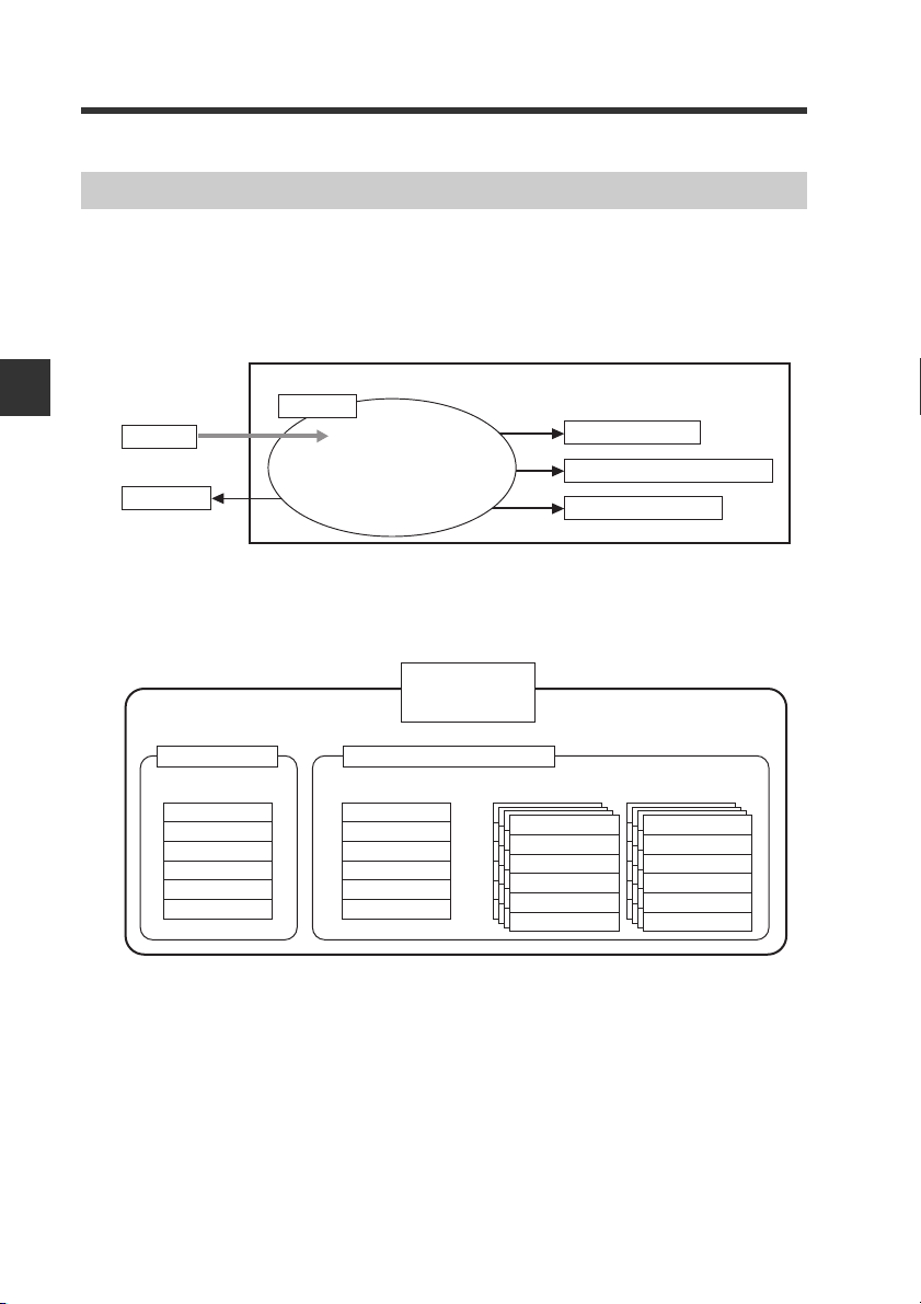
3
Parameter change
(3)
Control input indication execution
(4)
Initialization of settings
(5)
CB-EP100 or measuring instrument connected to the CB-EP100
Object
(1)
(2)
Service
Data output
Instance ID: 00H Instance ID: 01H Instance ID: 64H to 73H Instance ID: C8H to D7H
Instances for number of programs (16)
Attribute ID: 32DH
Attribute ID: 32EH
:
:
:
:
Attribute ID: 32DH
:
Setting area
:
:
:
:
:
Setting area
:
:
:
:
:
CB Object
(Class ID: 6BH)
CB-EP100 internal area
Measuring instrument internal area
3-4 Message Communication
Objects and Services
Message communication uses objects and services to send and receive data.
Executing a service (1) for a CB-EP100 object enables data read (2), parameter
change (3), control input (4), initialization of settings (5) and other operations.
Communicating with the LJ-V7000 Series
Taking CB Object as an example, one instance is provided for the measuring
instrument connected to the CB-EP100. Reading the attributes corresponding to the
measurement values of a measuring instrument instance using a service makes it
possible to read instance (01H=measuring instrument) measurement values.
3-34
- EtherNet/IP Network Unit CB-EP100 User’s Manual (LJ-V7000 Edition) -
Page 59

3-4 Message Communication
Reference
・ In EtherNet/IP (CIP), the method called "object modeling" is used to
express a device. The device is handled as a group of objects. Objects
abstractly express the configuration elements in the device. A class is a
group of objects expressing the configuration elements of the same
type. An instance actually expresses a specific object contained in a
class. Each instance in the class has the same attribute group, but each
attribute value is unique.
・ To execute a service for CB-EP100, send a command from the scanner.
The CB-EP100 then returns the service execution results as a response.
A command requires a service code, class ID (Class ID), instance ID
(Instance ID) and attribute ID (Attribute ID)*. When a parameter is
written, the command also requires a setting value (service data)*.
Command
Response
3
Communicating with the LJ-V7000 Series
Service code
㨯
Class ID
㨯
Instance ID
㨯
Attribute ID*
㨯
Service data*
㨯
General Status
㨯
Additional Status*
㨯
Service response data*
㨯
* Some of the commands to be used may not require the above items.
"Basic Format and Processing Flow of Message Communication"
(Page 3-37)
- EtherNet/IP Network Unit CB-EP100 User’s Manual (LJ-V7000 Edition) -
3-35
Page 60

3-4 Message Communication
Objects for use with the CB-EP100
The following describes the objects for use with the CB-EP100.
EtherNet/IP unit
3
Communicating with the LJ-V7000 Series
Identity
Object
TCP/IP
Interface
Object
Message
Router
Object
CB
Object
Connection
Manager
Object
Command
Response
Object Name Class ID Description
This object provides the statuses of the CB-EP100
CB Object 6BH
Identity Object 01H
Message Router
Object
Assembly Object 04H
Connection
Manager Object
TCP/IP Interface
Object
Ethernet Link Object F6H This object provides Ethernet status information. 5-22
and the Measuring instrument connected to the CBEP100 and writes and reads parameters. This object
is unique to the CB-EP100.
This object provides identification information,
general information and a reset service, etc.
This object provides connection points for message
02H
communication.
This object provides access to the devices via cyclic
communication. This object can be used to send data
to the devices that do not support cyclic
communication.
This object is used for connection-type
06H
communication.
This object provides the structure for setting the TCP/
F5H
IP network interface. You can set an IP address,
subnet mask and gateway, etc., in this object.
Assembly
Object
Ethernet
Link
Object
Reference
Page
3-40
5-10
5-13
5-14
5-16
5-18
3-36
- EtherNet/IP Network Unit CB-EP100 User’s Manual (LJ-V7000 Edition) -
Page 61

3-4 Message Communication
Basic Format and Processing Flow of Message Communication
The EtherNet/IP scanner and the CB-EP100 exchange Explicit messages for
communication. The following provides a basic example of the command format of
Explicit messages to be sent and the response format returned from the CB-EP100
to the scanner.
● Commands
・Command format
Item Description
Service code
Class ID Designates a class ID tailored to the service
Instance ID Designates an instance ID tailored to the service
Attribute ID Designates an attribute ID tailored to the service
Service Data Designates service data tailored to the service
*1 For details on usable services, refer to "CB Object (Class ID:6BH)" (Page 3-
40) or "Configuration Procedure for Control/Compact Logix Series" (Page 5-
6).
● Responses
・Response format
*1
Designates the service code to be used.
*1
to be used.
*1
to be used.
*1
to be used.
*1
to be used.
3
Communicating with the LJ-V7000 Series
Item Description
General status
Additional status Returns the additional status.
Service response
data
Returns a general status in respect to the command. 00H is returned when
the command ends normally.
Returns service response data in respect to the command.
- EtherNet/IP Network Unit CB-EP100 User’s Manual (LJ-V7000 Edition) -
3-37
Page 62

3-4 Message Communication
Command processing order and error response
Check whether each ID is within the supported range in the following order:
3
Communicating with the LJ-V7000 Series
Class ID check
Yes
Instance ID check
Yes
Service code check
Yes
Attribute ID check
Yes
Executes supported service process
Path Destination Unknown (05H)
returned as general status
No
Path Destination Unknown (05H)
returned as general status
No
Service not Supported (08H)
returned as general status
No
Attribute not Supported (14H)
returned as general status
No
● Supplement for object processing
• Get_Attribute_Single and Get_Attributes_All are executed, ignoring send service
data.
• The service (Get_Attributes_All, Reset) that does not designate an attribute ID is
executed, ignoring attribute ID.
• If Set_Attribute_Single is designated for an attribute which cannot be written (Set),
"0EH" (Attribute not settable) is returned as the general status.
• If Set_Attribute_Single for the writable attribute is designated and the writing size
is less than the attribute size, the general status "13H" (Not enough data) is
returned. If the writing size is greater than the attribute size, the service is
executed, ignoring the excessive data.
3-38
- EtherNet/IP Network Unit CB-EP100 User’s Manual (LJ-V7000 Edition) -
Page 63

3-4 Message Communication
Reading the CB Object Table
Reading the attribute ID
Example) Excerpt from CB Object attribute ID
(1) (2) (3) (4) (5) (6)
Service code
(hexadecimal)
0EH 32DH
(1) Service code Represents the Service code in hexadecimal notation.
(2) Attribute ID Represents the attribute ID in hexadecimal notation.
(3) Name Represents the attribute name.
(4) Description
(5) Attribute
(6) Data type Represents the attribute data type.
Attribute ID
(hexadecimal)
Item Description
Name Description
Measurement
value
OUT1
Describes the attribute and represents the data to be read and the range of
parameters that can be set.
Represents the direction of services for the attribute ID.
R (Read): The parameter read service (Get_Attribute_Single,
W (Write): The parameter write service (Set_Attribute_Single) can be used
OUT1 measurement value (integer) R
Get_Attributes_All) can be used to read the attribute value.
to write the attribute value.
Attribute
Data
Ty pe
DINT
3
Communicating with the LJ-V7000 Series
Data Type
The data type is defined in the EtherNet/IP specifications as follows:
Data Type Description
USINT Unsigned 8-bit integer 0 255
INT Signed 16-bit integer -32768 32767
UINT Unsigned 16-bit integer 0 65535
DINT Signed 32-bit integer -2147483648 2147483647
UDINT Unsigned 32-bit integer 0 4294967295
WORD Bit string: 16 bits - -
DWORD Bit string: 32 bits - -
STRING
Character string
(2-byte length information +
1-byte array per character)
Minimum Maximum
--
- EtherNet/IP Network Unit CB-EP100 User’s Manual (LJ-V7000 Edition) -
Range
3-39
Page 64

3
3-4 Message Communication
CB Object (Class ID:6BH)
The CB Object provides the CB-EP100 connection status and device write/read. This
object is unique to the CB-EP100.
● Overview of CB object
The following table shows a simplification of what data is included at positions
indicated by attribute IDs and instance IDs. (A gray area is reserved.) For actual
use, a service code and service data are also required. (In some cases, service
data may not be required.)
Communicating with the LJ-V7000 Series
・ R = read-only, RW = Read and write Also, with instance IDs of 100 to 115 and
200 to 215, the last two digits are the program number.
Attribute ID range Instance ID
Start ID End ID
DEC HEX DEC HEX
100 64
110 6E
119 77
160 A0
199 C7
768 300
848 350
849 351
862 35E
880 370
928 3A0−2447 98F 1520
2448 990
2943 B7F
3264 CC0
109 6D 10
−
118 76 9
−
159 9F 41
−
198 C6 39
−
767 2FF 569
−
847 34F 80
−
848 350 1
−
861 35D 13
−
879 36F 18
−
927 39F 48
−
2942 B7E 495
−
3263 CBF 321
−
3327 CFF 64
−
Quantity
0 1
R/W: Cyclic
data
Monitor data*
Port No.
R: Measuring
instrument
status
Error code/
device status
For unique service
(control input)
Monitor data
Profile data
Current
program
setting values
Device name/
revision
100 〜 115 200 〜 215
R: Active
measurement
area
Program setting
values of No**
(**: Last two digits of the instance ID)
R/W: Setting
write area
Program setting
values of No**
With instance ID = 1, the settings for the program number at that time can be
referred to.
* The same data as the measurement values/judgment values of instance ID = 1
can be acquired.
3-40
- EtherNet/IP Network Unit CB-EP100 User’s Manual (LJ-V7000 Edition) -
Page 65

● Services
3-4 Message Communication
Service
Code
0EH Read setting values
10H Writes setting values
4BH
4CH Clear errors
4DH
*1
4EH
*1
4FH
*1
50H
*1
57H
*1
58H
*1
59H
*1
5FH
Service Name Description
Reads setting values values from the CB-EP100 or from
measuring instrument connected to it. For examples, refer to
3-74.
Writes setting values values from the CB-EP100 or from
measuring instrument connected to it. For examples, refer to
page 3-75.
*1
*1
Switching the
programs
Control input
indication
Request to reflect
setting write area
Update of setting
write area
Initialization of
settings
Confirm profile data Confirms the profile data and copies it to the profile data area.
Set date and time
Acquires date and
time
Initializes all settings
Switches the program number of measuring instrument
connected to the CB-EP100 to program number specified in
the service data.
Clear the errors of the both the CB-EP100 and measuring
instrument.
Sets trigger and auto-zero and other control input of an
attribute ID to the status indicated in the service data.
Reflects the settings of the setting write area up to the
specified hierarchy level.
Updates the settings of the setting write area with the settings
of the specified hierarchy level.
Initializes the setting values for the program number
designated in the service data.
The date and time in the controller are set to match the date
and time designated in the service data.
Acquires the date and time of the measuring instrument.
Resets the setting area of the CB-EP100 and setting values
connected to the CB-EP100 to their default values.
*1 Cannot specify the CB-EP100 (instance ID = 00H).
3
Communicating with the LJ-V7000 Series
- EtherNet/IP Network Unit CB-EP100 User’s Manual (LJ-V7000 Edition) -
3-41
Page 66

3
3-4 Message Communication
● Responses
The responses made when each service is used are as follows:
(1) Read setting values Service code 0EH
(2) Write setting values Service code 10H
(3) Switching the programs Service code 4BH
(4) Clear errors Service code 4CH
(5) Input control data Service code 4DH
(6) Request to reflect setting write area Service code 4EH
(7) Update setting write area Service code 4FH
(8) Initialize program settings Service code 50H
(9) Confirm profile data Service code 57H
(10) Set date and time Service code 58H
Communicating with the LJ-V7000 Series
(11) Acquire date and time Service code 59H
(12) Initializes all settings Service code 5FH
General
status
00H
05H
08H
09H
0CH
0EH
13H
14H
1FH
20H
FEH
Service code (hexadecimal)
5 E 10 4B 4C 4D 4E 4F 50 57 58 59 5F
○○○○○○○○○○○○○
○○○○○○○○○○○○○
○−○○○○○○○○○○○
○−○○−○○○○○○○−
−−−○−○○○○○○○−
−−○−−−−−−−−−−
−−○−−○○○○○○○−
−○○○−○−−−−−−−
−○○○−−−−−−−−−
−−−−−−○−−−−−−
−○○○○○○○○○○○○
Description
The service has ended normally.
The instance ID is out of the range.
This service cannot be executed with the
specified instance ID.
The written data is out of the range.
Execution of control input failed.
A failure occurred during the execution of the
requested operation.
Writing was attempted to unwriteable attribute
ID.
The service data size is smaller than specified.
The attribute ID is out of the range.
This service is supported with the specified
instance ID, but it cannot be used with the
specified attribute ID. (Additional status
C350H)
The parameters associated with the request
are invalid. Returns the detailed code for
inconsistent settings that the measuring
instrument stores as additional status.*
A system error in the CB-EP100 or in a measuring instrument connected to the CBEP100.
* An additional status is a 4-digit hexadecimal value of ( ①②③④ H).
① : Target setting ⇒ One of 0 = no error and 7 = OUT setting
② : Program number⇒ 0 to F
③ : OUT number ⇒ 0 to F
④
: Error code
⇒
Depends on the cause of the error. Refer to "Error code list."
3-42
- EtherNet/IP Network Unit CB-EP100 User’s Manual (LJ-V7000 Edition) -
Page 67

3-4 Message Communication
● Error code list
The additional status returned for error code = 20H is as follows.
Target setting Error
Ty pe Category Code Description
No error 0000H No error
Cutoff frequency error for measurement value filter
Tolerance setting (upper/lower limits and hysteresis)
inconsistency
Scaling setting (measurement values 1/2 and span
after calculation) inconsistency
Offset setting (outside range of minimum display
unit) inconsistency
Auto-zero setting (outside range of minimum display
unit) inconsistency
Program setting OUT setting
7 ②③ 3H
7 ②③ 7H
7 ②③ 8H
7 ②③ 9H
7 ②③ AH
3
Communicating with the LJ-V7000 Series
- EtherNet/IP Network Unit CB-EP100 User’s Manual (LJ-V7000 Edition) -
3-43
Page 68

3-4 Message Communication
● Attributes
The attribute ID data below indicates something for each instance ID.
"Attribute" type - read or write - is indicated by R and W.
For details on data type, refer to page 3-39.
Instance ID = 0
Data stored and managed on the CB-EP100 can be obtained and changed.
3
Communicating with the LJ-V7000 Series
Service
(hexadecimal)
W:10H
R:0EH
Attribute
code
0EH
4CH None Error clear
ID
(hexadecimal)
64H
-
Monitor data
C6H
C7H
-
Reserved
34FH
350H Port No.
351H
Reserved
-
CFFH
Name Description and service data
The array for each parameter and
attribute ID is the same as the array
from 300H to 35DH in the following
table (Instance ID=1).
Specifies TCP/UDP port number, 2byte TCP port number, 2-byte UDP
port number (reserved).
Attribute
R
R/W
Data type
UINT
or
WORD or
DINT
struct of
UINT[2]
3-44
- EtherNet/IP Network Unit CB-EP100 User’s Manual (LJ-V7000 Edition) -
Page 69

3-4 Message Communication
Instance ID = 1
Data unique to a measuring instrument (LJ-V) connected to the CB-EP100 can be
obtained. The setting values obtained are the settings of the setting area currently in
operation for the program number at that point in time.
Service
code
(hexadecimal)
0EH
4DH
0EH
Attribute
ID
(hexadecimal)
65H
66H
67H Error code
68H Warning code
69H
-
6DH
6EH Trigger
6FH Auto-zero
70H Timing
71H Reset
72H Memory clear
73H Batch start
74H Batch end
75H Storage start
76H Storage end
78H
-
2FFH
300H System Status
301H
302H Valid status
303H
304H Alarm status
305H
-
307H
Name Description and service data
Setting values are
being collected
Save memory
status
Reserved
Reserved
Measuring in
strument status
Judgment
standby status
Reserved
Indicates whether or not the latest setting information of measuring instrument is currently being collected. 0
indicates that the information is not
being collected.
Indicates whether data is being written to the save memory. 0 indicates
that data is not being written.
Stores the error codes of connected a
measuring instrument.
Stores the warning codes of connected a measuring instrument.
For information on detailed formats,
refer to "Attribute IDs supported
by the instance service 4DH (control
input)" (Page 3-78).
For information on detailed formats,
refer to "Monitor Data (156 Words
(312 Bytes)) Assembly Instance
(Instance ID): 64H" (Page 3-9)
Attribute
Data type
DWORD
R
DWORD
UINT
UINT
-
Page 3-78
RWORD
3
Communicating with the LJ-V7000 Series
- EtherNet/IP Network Unit CB-EP100 User’s Manual (LJ-V7000 Edition) -
3-45
Page 70

3-4 Message Communication
3
Communicating with the LJ-V7000 Series
Service
code
(hexadecimal)
(hexadecimal)
0EH
0EH
0EH
0EH
0EH 326H
0EH 32BH
Attribute
ID
308H
30AH
30BH
-
310H
311H Timing status For information on detailed formats,
312H Auto-zero status
313H
-
316H
317H
318H
319H Reset completion
31AH
31BH
-
31EH
31FH Timing failed
320H Auto-zero failed
321H Reset failed
322H
323H
-
325H
327H
-
32AH
32CH Reserved
Name Description and service data
Judgment output
(HI)
Judgment output
(LO)
Judgment output
(GO)
Reserved
Reserved
Timing completion
Auto-zero
completion
External input
completion
Reserved
External input
failed
Reserved
Change
programs
Reserved
Current program
number
For information on detailed formats,
refer to "Monitor Data (156 Words
(312 Bytes)) Assembly Instance
(Instance ID): 64H" (Page 3-9)
refer to "Monitor Data (156 Words
(312 Bytes)) Assembly Instance
(Instance ID): 64H" (Page 3-9)
For information on detailed formats,
refer to "Monitor Data (156 Words
(312 Bytes)) Assembly Instance
(Instance ID): 64H" (Page 3-9)
For information on detailed formats,
refer to "Monitor Data (156 Words
(312 Bytes)) Assembly Instance
(Instance ID): 64H" (Page 3-9)
For information on detailed formats,
refer to "Monitor Data (156 Words
(312 Bytes)) Assembly Instance
(Instance ID): 64H" (Page 3-9)
For information on detailed formats,
refer to "Monitor Data (156 Words
(312 Bytes)) Assembly Instance
(Instance ID): 64H" (Page 3-9)
Attribute
Data type
RWORD309H
RWORD
RWORD
RWORD
RWORD
RUDINT
3-46
- EtherNet/IP Network Unit CB-EP100 User’s Manual (LJ-V7000 Edition) -
Page 71

3-4 Message Communication
Service
code
(hexadecimal)
0EH
Attribute
ID
(hexadecimal)
32DH
-
342H
Name Description and service data
Measurement
value OUT1
Measurement
value OUT2
Measurement
value OUT3
Measurement
value OUT4
Measurement
value OUT5
Measurement
value OUT6
Measurement
value OUT7
Measurement
value OUT8
Measurement
value OUT9
Measurement
value OUT10
Measurement
value OUT11
Measurement
value OUT12
Measurement
value OUT13
Measurement
value OUT14
Measurement
value OUT15
Measurement
value OUT16
OUT measurement
value update count
OUT1
OUT measurement
value update count
OUT2
OUT measurement
value update count
OUT3
OUT measurement
value update count
OUT4
OUT measurement
value update count
OUT5
OUT measurement
value update count
OUT6
For information on detailed formats,
refer to "Monitor Data (156 Words
(312 Bytes)) Assembly Instance
(Instance ID): 64H" (Page 3-9)
Attribute
R
Data type
3
Communicating with the LJ-V7000 Series
DINT
UDINT
- EtherNet/IP Network Unit CB-EP100 User’s Manual (LJ-V7000 Edition) -
3-47
Page 72

3-4 Message Communication
3
Communicating with the LJ-V7000 Series
Service
code
(hexadecimal)
0EH
Attribute
ID
(hexadecimal)
343H
-
356H
Name Description and service data
OUT measurement
value update count
OUT7
OUT measurement
value update count
OUT8
OUT measurement
value update count
OUT9
OUT measurement
value update count
OUT10
OUT measurement
value update count
OUT11
OUT measurement
value update count
OUT12
OUT measurement
value update count
OUT13
OUT measurement
value update count
OUT14
OUT measurement
value update count
OUT15
OUT measurement
value update count
OUT16
OUT value display
unit OUT1
OUT value display
unit OUT2
OUT value display
unit OUT3
OUT value display
unit OUT4
OUT value display
unit OUT5
OUT value display
unit OUT6
OUT value display
unit OUT7
OUT value display
unit OUT8
OUT value display
unit OUT9
OUT value display
unit OUT10
For information on detailed formats,
refer to "Monitor Data (156 Words
(312 Bytes)) Assembly Instance
(Instance ID): 64H" (Page 3-9)
Attribute
R
Data type
UDINT
DINT
3-48
- EtherNet/IP Network Unit CB-EP100 User’s Manual (LJ-V7000 Edition) -
Page 73

3-4 Message Communication
Service
code
(hexadecimal)
0EH
0EH
Attribute
ID
(hexadecimal)
357H
-
35DH
35EH
-
36FH
370H Profile data index Profile data index number (fixed to 1).
371H Profile data [0]
372H Profile data [1]
373H Profile data [2]
374H Profile data [3]
375H Profile data [4]
376H Profile data [5]
377H Profile data [6]
378H Profile data [7]
379H Profile data [8]
37AH Profile data [9]
37BH Profile data [10]
37CH Profile data [11]
37DH Profile data [12]
37EH Profile data [13]
37FH Profile data [14]
Name Description and service data
OUT value display
unit OUT11
OUT value display
unit OUT12
OUT value display
unit OUT13
OUT value display
unit OUT14
OUT value display
unit OUT15
OUT value display
unit OUT16
Storage point
Reserved
For information on detailed formats,
refer to "Monitor Data (156 Words
(312 Bytes)) Assembly Instance
(Instance ID): 64H" (Page 3-9)
Stores profile data [0] that has been
confirmed by the controller.
Stores profile data [1] that has been
confirmed by the controller.
Stores profile data [2] that has been
confirmed by the controller.
Stores profile data [3] that has been
confirmed by the controller.
Stores profile data [4] that has been
confirmed by the controller.
Stores profile data [5] that has been
confirmed by the controller.
Stores profile data [6] that has been
confirmed by the controller.
Stores profile data [7] that has been
confirmed by the controller.
Stores profile data [8] that has been
confirmed by the controller.
Stores profile data [9] that has been
confirmed by the controller.
Stores profile data [10] that has been
confirmed by the controller.
Stores profile data [11] that has been
confirmed by the controller.
Stores profile data [12] that has been
confirmed by the controller.
Stores profile data [13] that has been
confirmed by the controller.
Stores profile data [14] that has been
confirmed by the controller.
Attribute
Data type
RDINT
DINT
DINT[124]
(Profile
R
data is split
every 496
bytes.)
3
Communicating with the LJ-V7000 Series
- EtherNet/IP Network Unit CB-EP100 User’s Manual (LJ-V7000 Edition) -
3-49
Page 74

3-4 Message Communication
3
Communicating with the LJ-V7000 Series
3-50
Service
(hexadecimal)
code
0EH
Attribute
ID
(hexadecimal)
380H Profile data [15]
381H Profile data [16]
382H Profile data [17]
383H Profile data [18]
384H Profile data [19]
385H Profile data [20]
386H Profile data [21]
387H Profile data [22]
388H Profile data [23]
389H Profile data [24]
38AH Profile data [25]
38BH Profile data [26]
38CH Profile data [27]
38DH Profile data [28]
38EH Profile data [29]
38FH Profile data [30]
390H Profile data [31]
391H Profile data [32]
392H Profile data [33]
393H Profile data [34]
394H Profile data [35]
395H Profile data [36]
396H Profile data [37]
397H Profile data [38]
398H Profile data [39]
Name Description and service data
Stores profile data [15] that has been
confirmed by the controller.
Stores profile data [16] that has been
confirmed by the controller.
Stores profile data [17] that has been
confirmed by the controller.
Stores profile data [18] that has been
confirmed by the controller.
Stores profile data [19] that has been
confirmed by the controller.
Stores profile data [20] that has been
confirmed by the controller.
Stores profile data [21] that has been
confirmed by the controller.
Stores profile data [22] that has been
confirmed by the controller.
Stores profile data [23] that has been
confirmed by the controller.
Stores profile data [24] that has been
confirmed by the controller.
Stores profile data [25] that has been
confirmed by the controller.
Stores profile data [26] that has been
confirmed by the controller.
Stores profile data [27] that has been
confirmed by the controller.
Stores profile data [28] that has been
confirmed by the controller.
Stores profile data [29] that has been
confirmed by the controller.
Stores profile data [30] that has been
confirmed by the controller.
Stores profile data [31] that has been
confirmed by the controller.
Stores profile data [32] that has been
confirmed by the controller.
Stores profile data [33] that has been
confirmed by the controller.
Stores profile data [34] that has been
confirmed by the controller.
Stores profile data [35] that has been
confirmed by the controller.
Stores profile data [36] that has been
confirmed by the controller.
Stores profile data [37] that has been
confirmed by the controller.
Stores profile data [38] that has been
confirmed by the controller.
Stores profile data [39] that has been
confirmed by the controller.
- EtherNet/IP Network Unit CB-EP100 User’s Manual (LJ-V7000 Edition) -
Attribute
R
Data type
DINT[124]
(Profile
data is split
every 496
bytes.)
Page 75

3-4 Message Communication
Service
code
(hexadecimal)
0EH
Attribute
ID
(hexadecimal)
399H Profile data [40]
39AH Profile data [41]
39BH Profile data [42]
39CH Profile data [43]
39DH Profile data [44]
39EH Profile data [45]
39FH Profile data [46]
3A0H
-
98FH
Name Description and service data
Reserved
Stores profile data [40] that has been
confirmed by the controller.
Stores profile data [41] that has been
confirmed by the controller.
Stores profile data [42] that has been
confirmed by the controller.
Stores profile data [43] that has been
confirmed by the controller.
Stores profile data [44] that has been
confirmed by the controller.
Stores profile data [45] that has been
confirmed by the controller.
Stores profile data [46] that has been
confirmed by the controller.
Attribute
R
Data type
DINT[124]
(Profile
data is
split up
in 496 byte
pieces.)
3
Communicating with the LJ-V7000 Series
- EtherNet/IP Network Unit CB-EP100 User’s Manual (LJ-V7000 Edition) -
3-51
Page 76

3-4 Message Communication
3
Communicating with the LJ-V7000 Series
Service
code
(hexadecimal)
0EH
Attribute
ID
(hexadecimal)
990H
991H
992H
993H
994H
995H
996H
997H
998H
999H
99AH
99BH
99CH
99DH
99EH
99FH
-
9AFH
Name Description and service data
[OUT1 setting]
measurement
value hold count
[OUT1 setting]
measurement
value filter
[OUT1 setting]
measurement
value filter details
[OUT1 setting]
hold modes
[OUT1 setting]
scaling measurement value 1
[OUT1 setting]
scaling display
value 1
[OUT1 setting]
scaling measurement value 2
[OUT1 setting]
scaling display
value 2
[OUT1 setting]
offset
[OUT1 setting]
Upper tolerance limit
[OUT1 setting]
Lower tolerance limit
[OUT1 setting]
Tolerance hysteresis
[OUT1 setting]
zero reference value
[OUT1 setting]
Zero terminal
[OUT1 setting]
TIMING/RESET
terminal
Reserved
Specifies a measurement value hold
count (0 - 999).
0: OFF
1: Moving average
2: Low-pass filter
3: High-pass filter
Moving average mode
1: 16 times, 2: 64 times, 3: 256 times,
4: 1024 times, 5: 4096 times
High-pass, low-pass
1: 0.3 Hz, 2: 1 Hz, 3: 3 Hz, 4: 10 Hz,
5: 30 Hz, 6: 100 Hz, 7: 300 Hz,
8: 1000 Hz
0: Normal, 1: Peak hold, 2: Bottom
hold, 3: Peak-to-peak hold, 4: Average hold, 5: Sample hold, 6: Peak, 7:
Bottom, 8: Peak-to-peak, 9: Average
(0 to 5 can be set when batch measurement is OFF, and 6 to 9 can be
set when batch measurement is ON.)
Set each measurement value with the
following units depending on the measurement mode.
Length (height, width, etc.):
0.01μm units
Example:
⇒
1234560
Cross-sectional area:
0.00001mm
Example:
123456
Angle: 0.001°units
Example: 12340
0: None, 1: ZERO1, 2: ZERO2
0: None, 1: TIMNG1/RESET1,
2: TIMING2/RESET2
12345.60μm
2
units
⇒
1.23456mm
⇒
0: 4 times,
⇒
0: 0.1 Hz,
⇒
12.340°
Attribute
Data type
RDINT
2
3-52
- EtherNet/IP Network Unit CB-EP100 User’s Manual (LJ-V7000 Edition) -
Page 77

3-4 Message Communication
Service
code
(hexadecimal)
0EH
Attribute
ID
(hexadecimal)
9B0H
9B1H
9B2H
9B3H
9B4H
9B5H
9B6H
9B7H
9B8H
9B9H
9BAH
9BBH
9BCH
9BDH
9BEH
9BFH
-
9CFH
Name Description and service data
[OUT2 setting]
measurement
value hold count
[OUT2 setting]
measurement
value filter
[OUT2 setting]
measurement
value filter details
[OUT2 setting]
hold modes
[OUT2 setting]
scaling measurement value 1
[OUT2 setting]
scaling display
value 1
[OUT2 setting]
scaling measurement value 2
[OUT2 setting]
scaling display
value 2
[OUT2 setting]
offset
[OUT2 setting]
Upper tolerance limit
[OUT2 setting]
Lower tolerance limit
[OUT2 setting]
Tolerance hysteresis
[OUT2 setting]
zero reference value
[OUT2 setting]
Zero terminal
[OUT2 setting]
TIMING/RESET
terminal
Reserved
Specifies a measurement value hold
count (0 - 999).
0: OFF
1: Moving average
2: Low-pass filter
3: High-pass filter
Moving average mode
1: 16 times, 2: 64 times, 3: 256 times,
4: 1024 times, 5: 4096 times
High-pass, low-pass
1: 0.3 Hz, 2: 1 Hz, 3: 3 Hz, 4: 10 Hz,
5: 30 Hz, 6: 100 Hz, 7: 300 Hz,
8: 1000 Hz
0: Normal, 1: Peak hold, 2: Bottom
hold, 3: Peak-to-peak hold, 4: Average hold, 5: Sample hold, 6: Peak, 7:
Bottom, 8: Peak-to-peak, 9: Average
(0 to 5 can be set when batch measurement is OFF, and 6 to 9 can be
set when batch measurement is ON.)
Set each measurement value with the
following units depending on the measurement mode.
Length (height, width, etc.):
0.01μm units
Example:
⇒
1234560
Cross-sectional area:
0.00001mm
Example:
123456
Angle: 0.001°units
Example: 12340
0: None, 1: ZERO1, 2: ZERO2
0: None, 1: TIMNG1/RESET1,
2: TIMING2/RESET2
12345.60μm
2
units
⇒
1.23456mm
⇒
0: 4 times,
⇒
0: 0.1 Hz,
2
⇒
12.340°
Attribute
Data type
RDINT
3
Communicating with the LJ-V7000 Series
- EtherNet/IP Network Unit CB-EP100 User’s Manual (LJ-V7000 Edition) -
3-53
Page 78

3-4 Message Communication
3
Communicating with the LJ-V7000 Series
Service
code
(hexadecimal)
0EH
Attribute
ID
(hexadecimal)
9D0H
9D1H
9D2H
9D3H
9D4H
9D5H
9D6H
9D7H
9D8H
9D9H
9DAH
9DBH
9DCH
9DDH
9DEH
9DFH
-
9EFH
Name Description and service data
[OUT3 setting]
measurement
value hold count
[OUT3 setting]
measurement
value filter
[OUT3 setting]
measurement
value filter details
[OUT3 setting]
hold modes
[OUT3 setting]
scaling measurement value 1
[OUT3 setting]
scaling display
value 1
[OUT3 setting]
scaling measurement value 2
[OUT3 setting]
scaling display
value 2
[OUT3 setting]
offset
[OUT3 setting]
Upper tolerance limit
[OUT3 setting]
Lower tolerance limit
[OUT3 setting]
Tolerance hysteresis
[OUT3 setting]
zero reference value
[OUT3 setting]
Zero terminal
[OUT3 setting]
TIMING/RESET
terminal
Reserved
Specifies a measurement value hold
count (0 - 999).
0: OFF
1: Moving average
2: Low-pass filter
3: High-pass filter
Moving average mode
1: 16 times, 2: 64 times, 3: 256 times,
4: 1024 times, 5: 4096 times
High-pass, low-pass
1: 0.3 Hz, 2: 1 Hz, 3: 3 Hz, 4: 10 Hz,
5: 30 Hz, 6: 100 Hz, 7: 300 Hz,
8: 1000 Hz
0: Normal, 1: Peak hold, 2: Bottom
hold, 3: Peak-to-peak hold, 4: Average hold, 5: Sample hold, 6: Peak, 7:
Bottom, 8: Peak-to-peak, 9: Average
(0 to 5 can be set when batch measurement is OFF, and 6 to 9 can be
set when batch measurement is ON.)
Set each measurement value with the
following units depending on the measurement mode.
Length (height, width, etc.):
0.01μm units
Example:
⇒
1234560
Cross-sectional area:
0.00001mm
Example:
123456
Angle: 0.001°units
Example: 12340
0: None, 1: ZERO1, 2: ZERO2
0: None, 1: TIMNG1/RESET1,
2: TIMING2/RESET2
12345.60μm
2
units
⇒
1.23456mm
⇒
0: 4 times,
⇒
0: 0.1 Hz,
⇒
12.340°
Attribute
Data type
RDINT
2
3-54
- EtherNet/IP Network Unit CB-EP100 User’s Manual (LJ-V7000 Edition) -
Page 79

3-4 Message Communication
Service
code
(hexadecimal)
0EH
Attribute
ID
(hexadecimal)
9F0H
9F1H
9F2H
9F3H
9F4H
9F5H
9F6H
9F7H
9F8H
9F9H
9FAH
9FBH
9FCH
9FDH
9FEH
9FFH
-
A0FH
Name Description and service data
[OUT4 setting]
measurement
value hold count
[OUT4 setting]
measurement
value filter
[OUT4 setting]
measurement
value filter details
[OUT4 setting]
hold modes
[OUT4 setting]
scaling measurement value 1
[OUT4 setting]
scaling display
value 1
[OUT4 setting]
scaling measurement value 2
[OUT4 setting]
scaling display
value 2
[OUT4 setting]
offset
[OUT4 setting]
Upper tolerance limit
[OUT4 setting]
Lower tolerance limit
[OUT4 setting]
Tolerance hysteresis
[OUT4 setting]
zero reference value
[OUT4 setting]
Zero terminal
[OUT4 setting]
TIMING/RESET
terminal
Reserved
Specifies a measurement value hold
count (0 - 999).
0: OFF
1: Moving average
2: Low-pass filter
3: High-pass filter
Moving average mode
1: 16 times, 2: 64 times, 3: 256 times,
4: 1024 times, 5: 4096 times
High-pass, low-pass
1: 0.3 Hz, 2: 1 Hz, 3: 3 Hz, 4: 10 Hz,
5: 30 Hz, 6: 100 Hz, 7: 300 Hz,
8: 1000 Hz
0: Normal, 1: Peak hold, 2: Bottom
hold, 3: Peak-to-peak hold, 4: Average hold, 5: Sample hold, 6: Peak, 7:
Bottom, 8: Peak-to-peak, 9: Average
(0 to 5 can be set when batch measurement is OFF, and 6 to 9 can be
set when batch measurement is ON.)
Set each measurement value with the
following units depending on the measurement mode.
Length (height, width, etc.):
0.01μm units
Example:
⇒
1234560
Cross-sectional area:
0.00001mm
Example:
123456
Angle: 0.001°units
Example: 12340
0: None, 1: ZERO1, 2: ZERO2
0: None, 1: TIMNG1/RESET1,
2: TIMING2/RESET2
12345.60μm
2
units
⇒
1.23456mm
⇒
0: 4 times,
⇒
0: 0.1 Hz,
2
⇒
12.340°
Attribute
Data type
RDINT
3
Communicating with the LJ-V7000 Series
- EtherNet/IP Network Unit CB-EP100 User’s Manual (LJ-V7000 Edition) -
3-55
Page 80

3-4 Message Communication
3
Communicating with the LJ-V7000 Series
Service
code
(hexadecimal)
0EH
Attribute
ID
(hexadecimal)
A10H
A11H
A12H
A13H
A14H
A15H
A16H
A17H
A18H
A19H
A1AH
A1BH
A1CH
A1DH
A1EH
A1FH
-
A2FH
Name Description and service data
[OUT5 setting]
measurement
value hold count
[OUT5 setting]
measurement
value filter
[OUT5 setting]
measurement
value filter details
[OUT5 setting]
hold modes
[OUT5 setting]
scaling measurement value 1
[OUT5 setting]
scaling display
value 1
[OUT5 setting]
scaling measurement value 2
[OUT5 setting]
scaling display
value 2
[OUT5 setting]
offset
[OUT5 setting]
Upper tolerance limit
[OUT5 setting]
Lower tolerance limit
[OUT5 setting]
Tolerance hysteresis
[OUT5 setting]
zero reference value
[OUT5 setting]
Zero terminal
[OUT5 setting]
TIMING/RESET
terminal
Reserved
Specifies a measurement value hold
count (0 - 999).
0: OFF
1: Moving average
2: Low-pass filter
3: High-pass filter
Moving average mode
1: 16 times, 2: 64 times, 3: 256 times,
4: 1024 times, 5: 4096 times
High-pass, low-pass
1: 0.3 Hz, 2: 1 Hz, 3: 3 Hz, 4: 10 Hz,
5: 30 Hz, 6: 100 Hz, 7: 300 Hz,
8: 1000 Hz
0: Normal, 1: Peak hold, 2: Bottom
hold, 3: Peak-to-peak hold, 4: Average hold, 5: Sample hold, 6: Peak, 7:
Bottom, 8: Peak-to-peak, 9: Average
(0 to 5 can be set when batch measurement is OFF, and 6 to 9 can be
set when batch measurement is ON.)
Set each measurement value with the
following units depending on the measurement mode.
Length (height, width, etc.):
0.01μm units
Example:
⇒
1234560
Cross-sectional area:
0.00001mm
Example:
123456
Angle: 0.001°units
Example: 12340
0: None, 1: ZERO1, 2: ZERO2
0: None, 1: TIMNG1/RESET1,
2: TIMING2/RESET2
12345.60μm
2
units
⇒
1.23456mm
⇒
0: 4 times,
⇒
0: 0.1 Hz,
⇒
12.340°
Attribute
Data type
RDINT
2
3-56
- EtherNet/IP Network Unit CB-EP100 User’s Manual (LJ-V7000 Edition) -
Page 81

3-4 Message Communication
Service
code
(hexadecimal)
0EH
Attribute
ID
(hexadecimal)
A30H
A31H
A32H
A33H
A34H
A35H
A36H
A37H
A38H
A39H
A3AH
A3BH
A3CH
A3DH
A3EH
A3FH
-
A4FH
Name Description and service data
[OUT6 setting]
measurement
value hold count
[OUT6 setting]
measurement
value filter
[OUT6 setting]
measurement
value filter details
[OUT6 setting]
hold modes
[OUT6 setting]
scaling measurement value 1
[OUT6 setting]
scaling display
value 1
[OUT6 setting]
scaling measurement value 2
[OUT6 setting]
scaling display
value 2
[OUT6 setting]
offset
[OUT6 setting]
Upper tolerance limit
[OUT6 setting]
Lower tolerance limit
[OUT6 setting]
Tolerance hysteresis
[OUT6 setting]
zero reference value
[OUT6 setting]
Zero terminal
[OUT6 setting]
TIMING/RESET
terminal
Reserved
Specifies a measurement value hold
count (0 - 999).
0: OFF
1: Moving average
2: Low-pass filter
3: High-pass filter
Moving average mode
1: 16 times, 2: 64 times, 3: 256 times,
4: 1024 times, 5: 4096 times
High-pass, low-pass
1: 0.3 Hz, 2: 1 Hz, 3: 3 Hz, 4: 10 Hz,
5: 30 Hz, 6: 100 Hz, 7: 300 Hz,
8: 1000 Hz
0: Normal, 1: Peak hold, 2: Bottom
hold, 3: Peak-to-peak hold, 4: Average hold, 5: Sample hold, 6: Peak, 7:
Bottom, 8: Peak-to-peak, 9: Average
(0 to 5 can be set when batch measurement is OFF, and 6 to 9 can be
set when batch measurement is ON.)
Set each measurement value with the
following units depending on the measurement mode.
Length (height, width, etc.):
0.01μm units
Example:
⇒
1234560
Cross-sectional area:
0.00001mm
Example:
123456
Angle: 0.001°units
Example: 12340
0: None, 1: ZERO1, 2: ZERO2
0: None, 1: TIMNG1/RESET1,
2: TIMING2/RESET2
12345.60μm
2
units
⇒
1.23456mm
⇒
0: 4 times,
⇒
0: 0.1 Hz,
2
⇒
12.340°
Attribute
Data type
RDINT
3
Communicating with the LJ-V7000 Series
- EtherNet/IP Network Unit CB-EP100 User’s Manual (LJ-V7000 Edition) -
3-57
Page 82

3-4 Message Communication
3
Communicating with the LJ-V7000 Series
Service
code
(hexadecimal)
0EH
Attribute
ID
(hexadecimal)
A50H
A51H
A52H
A53H
A54H
A55H
A56H
A57H
A58H
A59H
A5AH
A5BH
A5CH
A5DH
A5EH
A5FH
-
A6FH
Name Description and service data
[OUT7 setting]
measurement
value hold count
[OUT7 setting]
measurement
value filter
[OUT7 setting]
measurement
value filter details
[OUT7 setting]
hold modes
[OUT7 setting]
scaling measurement value 1
[OUT7 setting]
scaling display
value 1
[OUT7 setting]
scaling measurement value 2
[OUT7 setting]
scaling display
value 2
[OUT7 setting]
offset
[OUT7 setting]
Upper tolerance limit
[OUT7 setting]
Lower tolerance limit
[OUT7 setting]
Tolerance hysteresis
[OUT7 setting]
zero reference value
[OUT7 setting]
Zero terminal
[OUT7 setting]
TIMING/RESET
terminal
Reserved
Specifies a measurement value hold
count (0 - 999).
0: OFF
1: Moving average
2: Low-pass filter
3: High-pass filter
Moving average mode
1: 16 times, 2: 64 times, 3: 256 times,
4: 1024 times, 5: 4096 times
High-pass, low-pass
1: 0.3 Hz, 2: 1 Hz, 3: 3 Hz, 4: 10 Hz,
5: 30 Hz, 6: 100 Hz, 7: 300 Hz,
8: 1000 Hz
0: Normal, 1: Peak hold, 2: Bottom
hold, 3: Peak-to-peak hold, 4: Average hold, 5: Sample hold, 6: Peak, 7:
Bottom, 8: Peak-to-peak, 9: Average
(0 to 5 can be set when batch measurement is OFF, and 6 to 9 can be
set when batch measurement is ON.)
Set each measurement value with the
following units depending on the measurement mode.
Length (height, width, etc.):
0.01μm units
Example:
⇒
1234560
Cross-sectional area:
0.00001mm
Example:
123456
Angle: 0.001°units
Example: 12340
0: None, 1: ZERO1, 2: ZERO2
0: None, 1: TIMNG1/RESET1,
2: TIMING2/RESET2
12345.60μm
2
units
⇒
1.23456mm
⇒
0: 4 times,
⇒
0: 0.1 Hz,
⇒
12.340°
Attribute
Data type
RDINT
2
3-58
- EtherNet/IP Network Unit CB-EP100 User’s Manual (LJ-V7000 Edition) -
Page 83

3-4 Message Communication
Service
code
(hexadecimal)
0EH
Attribute
ID
(hexadecimal)
A70H
A71H
A72H
A73H
A74H
A75H
A76H
A77H
A78H
A79H
A7AH
A7BH
A7CH
A7DH
A7EH
A7FH
-
A8FH
Name Description and service data
[OUT8 setting]
measurement
value hold count
[OUT8 setting]
measurement
value filter
[OUT8 setting]
measurement
value filter details
[OUT8 setting]
hold modes
[OUT8 setting]
scaling measurement value 1
[OUT8 setting]
scaling display
value 1
[OUT8 setting]
scaling measurement value 2
[OUT8 setting]
scaling display
value 2
[OUT8 setting]
offset
[OUT8 setting]
Upper tolerance limit
[OUT8 setting]
Lower tolerance limit
[OUT8 setting]
Tolerance hysteresis
[OUT8 setting]
zero reference value
[OUT8 setting]
Zero terminal
[OUT8 setting]
TIMING/RESET
terminal
Reserved
Specifies a measurement value hold
count (0 - 999).
0: OFF
1: Moving average
2: Low-pass filter
3: High-pass filter
Moving average mode
1: 16 times, 2: 64 times, 3: 256 times,
4: 1024 times, 5: 4096 times
High-pass, low-pass
1: 0.3 Hz, 2: 1 Hz, 3: 3 Hz, 4: 10 Hz,
5: 30 Hz, 6: 100 Hz, 7: 300 Hz,
8: 1000 Hz
0: Normal, 1: Peak hold, 2: Bottom
hold, 3: Peak-to-peak hold, 4: Average hold, 5: Sample hold, 6: Peak, 7:
Bottom, 8: Peak-to-peak, 9: Average
(0 to 5 can be set when batch measurement is OFF, and 6 to 9 can be
set when batch measurement is ON.)
Set each measurement value with the
following units depending on the measurement mode.
Length (height, width, etc.):
0.01μm units
Example:
⇒
1234560
Cross-sectional area:
0.00001mm
Example:
123456
Angle: 0.001°units
Example: 12340
0: None, 1: ZERO1, 2: ZERO2
0: None, 1: TIMNG1/RESET1,
2: TIMING2/RESET2
12345.60μm
2
units
⇒
1.23456mm
⇒
0: 4 times,
⇒
0: 0.1 Hz,
2
⇒
12.340°
Attribute
Data type
RDINT
3
Communicating with the LJ-V7000 Series
- EtherNet/IP Network Unit CB-EP100 User’s Manual (LJ-V7000 Edition) -
3-59
Page 84

3-4 Message Communication
3
Communicating with the LJ-V7000 Series
Service
code
(hexadecimal)
0EH
Attribute
ID
(hexadecimal)
A90H
A91H
A92H
A93H
A94H
A95H
A96H
A97H
A98H
A99H
A9AH
A9BH
A9CH
A9DH
A9EH
A9FH
-
AAFH
Name Description and service data
[OUT9 setting]
measurement
value hold count
[OUT9 setting]
measurement
value filter
[OUT9 setting]
measurement
value filter details
[OUT9 setting]
hold modes
[OUT9 setting]
scaling measurement value 1
[OUT9 setting]
scaling display
value 1
[OUT9 setting]
scaling measurement value 2
[OUT9 setting]
scaling display
value 2
[OUT9 setting]
offset
[OUT9 setting]
Upper tolerance limit
[OUT9 setting]
Lower tolerance limit
[OUT9 setting]
Tolerance hysteresis
[OUT9 setting]
zero reference value
[OUT9 setting]
Zero terminal
[OUT9 setting]
TIMING/RESET
terminal
Reserved
Specifies a measurement value hold
count (0 - 999).
0: OFF
1: Moving average
2: Low-pass filter
3: High-pass filter
Moving average mode
1: 16 times, 2: 64 times, 3: 256 times,
4: 1024 times, 5: 4096 times
High-pass, low-pass
1: 0.3 Hz, 2: 1 Hz, 3: 3 Hz, 4: 10 Hz,
5: 30 Hz, 6: 100 Hz, 7: 300 Hz,
8: 1000 Hz
0: Normal, 1: Peak hold, 2: Bottom
hold, 3: Peak-to-peak hold, 4: Average hold, 5: Sample hold, 6: Peak, 7:
Bottom, 8: Peak-to-peak, 9: Average
(0 to 5 can be set when batch measurement is OFF, and 6 to 9 can be
set when batch measurement is ON.)
Set each measurement value with the
following units depending on the measurement mode.
Length (height, width, etc.):
0.01μm units
Example:
⇒
1234560
Cross-sectional area:
0.00001mm
Example:
123456
Angle: 0.001°units
Example: 12340
0: None, 1: ZERO1, 2: ZERO2
0: None, 1: TIMNG1/RESET1,
2: TIMING2/RESET2
12345.60μm
2
units
⇒
1.23456mm
⇒
0: 4 times,
⇒
0: 0.1 Hz,
⇒
12.340°
Attribute
Data type
RDINT
2
3-60
- EtherNet/IP Network Unit CB-EP100 User’s Manual (LJ-V7000 Edition) -
Page 85

3-4 Message Communication
Service
code
(hexadecimal)
0EH
Attribute
ID
(hexadecimal)
AB0H
AB1H
AB2H
AB3H
AB4H
AB5H
AB6H
AB7H
AB8H
AB9H
ABAH
ABBH
ABCH
ABDH
ABEH
ABFH
-
ACFH
Name Description and service data
[OUT10 setting]
measurement
value hold count
[OUT10 setting]
measurement
value filter
[OUT10 setting]
measurement
value filter details
[OUT10 setting]
hold modes
[OUT10 setting]
scaling measurement value 1
[OUT10 setting]
scaling display
value 1
[OUT10 setting]
scaling measurement value 2
[OUT10 setting]
scaling display
value 2
[OUT10 setting]
offset
[OUT10 setting]
Upper tolerance limit
[OUT10 setting]
Lower tolerance limit
[OUT10 setting]
Tolerance hysteresis
[OUT10 setting]
zero reference value
[OUT10 setting]
Zero terminal
[OUT10 setting]
TIMING/RESET
terminal
Reserved
Specifies a measurement value hold
count (0 - 999).
0: OFF
1: Moving average
2: Low-pass filter
3: High-pass filter
Moving average mode
1: 16 times, 2: 64 times, 3: 256 times,
4: 1024 times, 5: 4096 times
High-pass, low-pass
1: 0.3 Hz, 2: 1 Hz, 3: 3 Hz, 4: 10 Hz,
5: 30 Hz, 6: 100 Hz, 7: 300 Hz,
8: 1000 Hz
0: Normal, 1: Peak hold, 2: Bottom
hold, 3: Peak-to-peak hold, 4: Average hold, 5: Sample hold, 6: Peak, 7:
Bottom, 8: Peak-to-peak, 9: Average
(0 to 5 can be set when batch measurement is OFF, and 6 to 9 can be
set when batch measurement is ON.)
Set each measurement value with the
following units depending on the measurement mode.
Length (height, width, etc.):
0.01μm units
Example:
⇒
1234560
Cross-sectional area:
0.00001mm
Example:
123456
Angle: 0.001°units
Example: 12340
0: None, 1: ZERO1, 2: ZERO2
0: None, 1: TIMNG1/RESET1,
2: TIMING2/RESET2
12345.60μm
2
units
⇒
1.23456mm
⇒
0: 4 times,
⇒
0: 0.1 Hz,
2
⇒
12.340°
Attribute
Data type
RDINT
3
Communicating with the LJ-V7000 Series
- EtherNet/IP Network Unit CB-EP100 User’s Manual (LJ-V7000 Edition) -
3-61
Page 86

3-4 Message Communication
3
Communicating with the LJ-V7000 Series
Service
code
(hexadecimal)
0EH
Attribute
ID
(hexadecimal)
AD0H
AD1H
AD2H
AD3H
AD4H
AD5H
AD6H
AD7H
AD8H
AD9H
ADAH
ADBH
ADCH
ADDH
ADEH
ADFH
-
AEFH
Name Description and service data
[OUT11 setting]
measurement
value hold count
[OUT11 setting]
measurement
value filter
[OUT11 setting]
measurement
value filter details
[OUT11 setting]
hold modes
[OUT11 setting]
scaling measurement value 1
[OUT11 setting]
scaling display
value 1
[OUT11 setting]
scaling measurement value 2
[OUT11 setting]
scaling display
value 2
[OUT11 setting]
offset
[OUT11 setting]
Upper tolerance limit
[OUT11 setting]
Lower tolerance limit
[OUT11 setting]
Tolerance hysteresis
[OUT11 setting]
zero reference value
[OUT11 setting]
Zero terminal
[OUT11 setting]
TIMING/RESET
terminal
Reserved
Specifies a measurement value hold
count (0 - 999).
0: OFF
1: Moving average
2: Low-pass filter
3: High-pass filter
Moving average mode
1: 16 times, 2: 64 times, 3: 256 times,
4: 1024 times, 5: 4096 times
High-pass, low-pass
1: 0.3 Hz, 2: 1 Hz, 3: 3 Hz, 4: 10 Hz,
5: 30 Hz, 6: 100 Hz, 7: 300 Hz,
8: 1000 Hz
0: Normal, 1: Peak hold, 2: Bottom
hold, 3: Peak-to-peak hold, 4: Average hold, 5: Sample hold, 6: Peak, 7:
Bottom, 8: Peak-to-peak, 9: Average
(0 to 5 can be set when batch measurement is OFF, and 6 to 9 can be
set when batch measurement is ON.)
Set each measurement value with the
following units depending on the measurement mode.
Length (height, width, etc.):
0.01μm units
Example:
⇒
1234560
Cross-sectional area:
0.00001mm
Example:
123456
Angle: 0.001°units
Example: 12340
0: None, 1: ZERO1, 2: ZERO2
0: None, 1: TIMNG1/RESET1,
2: TIMING2/RESET2
12345.60μm
2
units
⇒
1.23456mm
⇒
0: 4 times,
⇒
0: 0.1 Hz,
⇒
12.340°
Attribute
Data type
RDINT
2
3-62
- EtherNet/IP Network Unit CB-EP100 User’s Manual (LJ-V7000 Edition) -
Page 87

3-4 Message Communication
Service
code
(hexadecimal)
0EH
Attribute
ID
(hexadecimal)
AF0H
AF1H
AF2H
AF3H
AF4H
AF5H
AF6H
AF7H
AF8H
AF9H
AFAH
AFBH
AFCH
AFDH
AFEH
AFFH
-
B0FH
Name Description and service data
[OUT12 setting]
measurement
value hold count
[OUT12 setting]
measurement
value filter
[OUT12 setting]
measurement
value filter details
[OUT12 setting]
hold modes
[OUT12 setting]
scaling measurement value 1
[OUT12 setting]
scaling display
value 1
[OUT12 setting]
scaling measurement value 2
[OUT12 setting]
scaling display
value 2
[OUT12 setting]
offset
[OUT12 setting]
Upper tolerance limit
[OUT12 setting]
Lower tolerance limit
[OUT12 setting]
Tolerance hysteresis
[OUT12 setting]
zero reference value
[OUT12 setting]
Zero terminal
[OUT12 setting]
TIMING/RESET
terminal
Reserved
Specifies a measurement value hold
count (0 - 999).
0: OFF
1: Moving average
2: Low-pass filter
3: High-pass filter
Moving average mode
1: 16 times, 2: 64 times, 3: 256 times,
4: 1024 times, 5: 4096 times
High-pass, low-pass
1: 0.3 Hz, 2: 1 Hz, 3: 3 Hz, 4: 10 Hz,
5: 30 Hz, 6: 100 Hz, 7: 300 Hz,
8: 1000 Hz
0: Normal, 1: Peak hold, 2: Bottom
hold, 3: Peak-to-peak hold, 4: Average hold, 5: Sample hold, 6: Peak, 7:
Bottom, 8: Peak-to-peak, 9: Average
(0 to 5 can be set when batch measurement is OFF, and 6 to 9 can be
set when batch measurement is ON.)
Set each measurement value with the
following units depending on the measurement mode.
Length (height, width, etc.):
0.01μm units
Example:
⇒
1234560
Cross-sectional area:
0.00001mm
Example:
123456
Angle: 0.001°units
Example: 12340
0: None, 1: ZERO1, 2: ZERO2
0: None, 1: TIMNG1/RESET1,
2: TIMING2/RESET2
12345.60μm
2
units
⇒
1.23456mm
⇒
0: 4 times,
⇒
0: 0.1 Hz,
2
⇒
12.340°
Attribute
Data type
RDINT
3
Communicating with the LJ-V7000 Series
- EtherNet/IP Network Unit CB-EP100 User’s Manual (LJ-V7000 Edition) -
3-63
Page 88

3-4 Message Communication
3
Communicating with the LJ-V7000 Series
Service
code
(hexadecimal)
0EH
Attribute
ID
(hexadecimal)
B10H
B11H
B12H
B13H
B14H
B15H
B16H
B17H
B18H
B19H
B1AH
B1BH
B1CH
B1DH
B1EH
B1FH
-
B2FH
Name Description and service data
[OUT13 setting]
measurement
value hold count
[OUT13 setting]
measurement
value filter
[OUT13 setting]
measurement
value filter details
[OUT13 setting]
hold modes
[OUT13 setting]
scaling measurement value 1
[OUT13 setting]
scaling display
value 1
[OUT13 setting]
scaling measurement value 2
[OUT13 setting]
scaling display
value 2
[OUT13 setting]
offset
[OUT13 setting]
Upper tolerance limit
[OUT13 setting]
Lower tolerance limit
[OUT13 setting]
Tolerance hysteresis
[OUT13 setting]
zero reference value
[OUT13 setting]
Zero terminal
[OUT13 setting]
TIMING/RESET
terminal
Reserved
Specifies a measurement value hold
count (0 - 999).
0: OFF
1: Moving average
2: Low-pass filter
3: High-pass filter
Moving average mode
1: 16 times, 2: 64 times, 3: 256 times,
4: 1024 times, 5: 4096 times
High-pass, low-pass
1: 0.3 Hz, 2: 1 Hz, 3: 3 Hz, 4: 10 Hz,
5: 30 Hz, 6: 100 Hz, 7: 300 Hz,
8: 1000 Hz
0: Normal, 1: Peak hold, 2: Bottom
hold, 3: Peak-to-peak hold, 4: Average hold, 5: Sample hold, 6: Peak, 7:
Bottom, 8: Peak-to-peak, 9: Average
(0 to 5 can be set when batch measurement is OFF, and 6 to 9 can be
set when batch measurement is ON.)
Set each measurement value with the
following units depending on the measurement mode.
Length (height, width, etc.):
0.01μm units
Example:
⇒
1234560
Cross-sectional area:
0.00001mm
Example:
123456
Angle: 0.001°units
Example: 12340
0: None, 1: ZERO1, 2: ZERO2
0: None, 1: TIMNG1/RESET1,
2: TIMING2/RESET2
12345.60μm
2
units
⇒
1.23456mm
⇒
0: 4 times,
⇒
0: 0.1 Hz,
⇒
12.340°
Attribute
Data type
RDINT
2
3-64
- EtherNet/IP Network Unit CB-EP100 User’s Manual (LJ-V7000 Edition) -
Page 89

3-4 Message Communication
Service
code
(hexadecimal)
0EH
Attribute
ID
(hexadecimal)
B30H
B31H
B32H
B33H
B34H
B35H
B36H
B37H
B38H
B39H
B3AH
B3BH
B3CH
B3DH
B3EH
B3FH
-
B4FH
Name Description and service data
[OUT14 setting]
measurement
value hold count
[OUT14 setting]
measurement
value filter
[OUT14 setting]
measurement
value filter details
[OUT14 setting]
hold modes
[OUT14 setting]
scaling measurement value 1
[OUT14 setting]
scaling display
value 1
[OUT14 setting]
scaling measurement value 2
[OUT14 setting]
scaling display
value 2
[OUT14 setting]
offset
[OUT14 setting]
Upper tolerance limit
[OUT14 setting]
Lower tolerance limit
[OUT14 setting]
Tolerance hysteresis
[OUT14 setting]
zero reference value
[OUT14 setting]
Zero terminal
[OUT14 setting]
TIMING/RESET
terminal
Reserved
Specifies a measurement value hold
count (0 - 999).
0: OFF
1: Moving average
2: Low-pass filter
3: High-pass filter
Moving average mode
1: 16 times, 2: 64 times, 3: 256 times,
4: 1024 times, 5: 4096 times
High-pass, low-pass
1: 0.3 Hz, 2: 1 Hz, 3: 3 Hz, 4: 10 Hz,
5: 30 Hz, 6: 100 Hz, 7: 300 Hz,
8: 1000 Hz
0: Normal, 1: Peak hold, 2: Bottom
hold, 3: Peak-to-peak hold, 4: Average hold, 5: Sample hold, 6: Peak, 7:
Bottom, 8: Peak-to-peak, 9: Average
(0 to 5 can be set when batch measurement is OFF, and 6 to 9 can be
set when batch measurement is ON.)
Set each measurement value with the
following units depending on the measurement mode.
Length (height, width, etc.):
0.01μm units
Example:
⇒
1234560
Cross-sectional area:
0.00001mm
Example:
123456
Angle: 0.001°units
Example: 12340
0: None, 1: ZERO1, 2: ZERO2
0: None, 1: TIMNG1/RESET1,
2: TIMING2/RESET2
12345.60μm
2
units
⇒
1.23456mm
⇒
0: 4 times,
⇒
0: 0.1 Hz,
2
⇒
12.340°
Attribute
Data type
RDINT
3
Communicating with the LJ-V7000 Series
- EtherNet/IP Network Unit CB-EP100 User’s Manual (LJ-V7000 Edition) -
3-65
Page 90

3-4 Message Communication
3
Communicating with the LJ-V7000 Series
Service
code
(hexadecimal)
0EH
Attribute
ID
(hexadecimal)
B50H
B51H
B52H
B53H
B54H
B55H
B56H
B57H
B58H
B59H
B5AH
B5BH
B5CH
B5DH
B5EH
B5FH
-
B6FH
Name Description and service data
[OUT15 setting]
measurement
value hold count
[OUT15 setting]
measurement
value filter
[OUT15 setting]
measurement
value filter details
[OUT15 setting]
hold modes
[OUT15 setting]
scaling measurement value 1
[OUT15 setting]
scaling display
value 1
[OUT15 setting]
scaling measurement value 2
[OUT15 setting]
scaling display
value 2
[OUT15 setting]
offset
[OUT15 setting]
Upper tolerance limit
[OUT15 setting]
Lower tolerance limit
[OUT15 setting]
Tolerance hysteresis
[OUT15 setting]
zero reference value
[OUT15 setting]
Zero terminal
[OUT15 setting]
TIMING/RESET
terminal
Reserved
Specifies a measurement value hold
count (0 - 999).
0: OFF
1: Moving average
2: Low-pass filter
3: High-pass filter
Moving average mode
1: 16 times, 2: 64 times, 3: 256 times,
4: 1024 times, 5: 4096 times
High-pass, low-pass
1: 0.3 Hz, 2: 1 Hz, 3: 3 Hz, 4: 10 Hz,
5: 30 Hz, 6: 100 Hz, 7: 300 Hz,
8: 1000 Hz
0: Normal, 1: Peak hold, 2: Bottom
hold, 3: Peak-to-peak hold, 4: Average hold, 5: Sample hold, 6: Peak, 7:
Bottom, 8: Peak-to-peak, 9: Average
(0 to 5 can be set when batch measurement is OFF, and 6 to 9 can be
set when batch measurement is ON.)
Set each measurement value with the
following units depending on the measurement mode.
Length (height, width, etc.):
0.01μm units
Example:
⇒
1234560
Cross-sectional area:
0.00001mm
Example:
123456
Angle: 0.001°units
Example: 12340
0: None, 1: ZERO1, 2: ZERO2
0: None, 1: TIMNG1/RESET1,
2: TIMING2/RESET2
12345.60μm
2
units
⇒
1.23456mm
⇒
0: 4 times,
⇒
0: 0.1 Hz,
⇒
12.340°
Attribute
Data type
RDINT
2
3-66
- EtherNet/IP Network Unit CB-EP100 User’s Manual (LJ-V7000 Edition) -
Page 91

3-4 Message Communication
Service
code
(hexadecimal)
0EH
Attribute
ID
(hexadecimal)
B70H
B71H
B72H
B73H
B74H
B75H
B76H
B77H
B78H
B79H
B7AH
B7BH
B7CH
B7DH
B7EH
B7FH
-
CBFH
Name Description and service data
[OUT16 setting]
measurement
value hold count
[OUT16 setting]
measurement
value filter
[OUT16 setting]
measurement
value filter details
[OUT16 setting]
hold modes
[OUT16 setting]
scaling measurement value 1
[OUT16 setting]
scaling display
value 1
[OUT16 setting]
scaling measurement value 2
[OUT16 setting]
scaling display
value 2
[OUT16 setting]
offset
[OUT16 setting]
Upper tolerance limit
[OUT16 setting]
Lower tolerance limit
[OUT16 setting]
Tolerance hysteresis
[OUT16 setting]
zero reference value
[OUT16 setting]
Zero terminal
[OUT16 setting]
TIMING/RESET
terminal
Reserved
Specifies a measurement value hold
count (0 - 999).
0: OFF
1: Moving average
2: Low-pass filter
3: High-pass filter
Moving average mode
1: 16 times, 2: 64 times, 3: 256 times,
4: 1024 times, 5: 4096 times
High-pass, low-pass
1: 0.3 Hz, 2: 1 Hz, 3: 3 Hz, 4: 10 Hz,
5: 30 Hz, 6: 100 Hz, 7: 300 Hz,
8: 1000 Hz
0: Normal, 1: Peak hold, 2: Bottom
hold, 3: Peak-to-peak hold, 4: Average hold, 5: Sample hold, 6: Peak, 7:
Bottom, 8: Peak-to-peak, 9: Average
(0 to 5 can be set when batch measurement is OFF, and 6 to 9 can be
set when batch measurement is ON.)
Set each measurement value with the
following units depending on the measurement mode.
Length (height, width, etc.):
0.01μm units
Example:
⇒
1234560
Cross-sectional area:
0.00001mm
Example:
123456
Angle: 0.001°units
Example: 12340
0: None, 1: ZERO1, 2: ZERO2
0: None, 1: TIMNG1/RESET1,
2: TIMING2/RESET2
12345.60μm
2
units
⇒
1.23456mm
⇒
0: 4 times,
⇒
0: 0.1 Hz,
2
⇒
12.340°
Attribute
Data type
RDINT
3
Communicating with the LJ-V7000 Series
- EtherNet/IP Network Unit CB-EP100 User’s Manual (LJ-V7000 Edition) -
3-67
Page 92

3-4 Message Communication
3
Communicating with the LJ-V7000 Series
Service
(hexadecimal)
Attribute
code
0EH CC0H device name Indicates the device name. R STRING
0EH
0EH
0EH
4BH None Program switch
4CH None Error clear Clears errors - -
4EH None
4FH None
50H None
57H None
58H None Daily settings Date and time information W
59H None
5FH None
ID
(hexadecimal)
CC1H
-
CE3H
CE4H Product code
CE5H Revision
CE6H Controller model
CE7H Series code Indicates the series code. R INT
CE8H Series version Indicates the series version. R INT
CE9H Device type Indicates the device type. R INT
CEAH Reserved
CEBH
CECH
CEDH
-
CF9H
CFAH
CFBH
CFCH
-
CFFH
Name Description and service data
Reserved
Stores the product code of the measuring instrument.
Stores the revision.
USINT[0]: Major revision
USINT[1]: Minor revision
Indicates the measuring instrument
model.
Connected head
model [0]
Connected head
model [1]
Reserved
Connected unit
model [0]
Connected unit
model [1]
Reserved
Request to reflect
setting write area
Update of setting
write area
Initialize specified
program number
settings
Profile data confirmed
Acquires date
and time
Initializes all settings
Indicates the head model. R STRING
Indicates the head model. R STRING
Indicates the connected unit model. R STRING
Indicates the connected unit model. R STRING
Specifies the number of the program
to change to.
Specifies the reflection destination
area.
Specifies Update source area. W UDINT
Program number W UDINT
Copies the latest profile data to the
areas that can be acquired with the
attribute IDs 370H to 39FH.
Date and time information in service
response
Returns the all settings to their default
values.
Attribute
Data type
RINT
R
USINT[2]
RSTRING
WUDINT
WUDINT
RUDINT
UDINT[7]
R
UDINT[7]
--
struct of
struct of
struct of
3-68
- EtherNet/IP Network Unit CB-EP100 User’s Manual (LJ-V7000 Edition) -
Page 93

3-4 Message Communication
Instance ID = 100 to 115
You can refer to the setting value of each OUT number of the setting area currently in
operation for the program number indicated by the last two digits of the instance ID
during operation of a measuring instrument connected to the CB-EP100. (Writing is
not possible.)
Service code
(hexadecimal)
0EH
0EH
0EH
0EH
0EH
0EH
0EH
0EH
Attribute ID
(hexadecimal)
64H
-
98FH
990H
-
99EH
99FH
-
9AFH
9B0H
-
9BEH
9BFH
-
9CFH
9D0H
-
9DEH
9DFH
-
9EFH
9F0H
-
9FEH
9FFH
-
A0FH
A10H
-
A1EH
A1FH
-
A2FH
A30H
-
A3EH
A3FH
-
A4FH
A50H
-
A5EH
A5FH
-
A6FH
A70H
-
A7EH
A7FH
-
A8FH
Name Description and service data
Reserved
OUT1 setting
Reserved
OUT2 setting
Reserved
OUT3 setting
Reserved
OUT4 setting
Reserved
OUT5 setting
Reserved
OUT6 setting
Reserved
OUT7 setting
Reserved
OUT8 setting
Reserved
Refer to the same address as instance
ID = 1
Refer to the same address as instance
ID = 1
Refer to the same address as instance
ID = 1
Refer to the same address as instance
ID = 1
Refer to the same address as instance
ID = 1
Refer to the same address as instance
ID = 1
Refer to the same address as instance
ID = 1
Refer to the same address as instance
ID = 1
Attribute
Data
type
RDINT
RDINT
RDINT
RDINT
RDINT
RDINT
RDINT
RDINT
3
Communicating with the LJ-V7000 Series
- EtherNet/IP Network Unit CB-EP100 User’s Manual (LJ-V7000 Edition) -
3-69
Page 94

3-4 Message Communication
3
Communicating with the LJ-V7000 Series
Service code
(hexadecimal)
0EH
0EH
0EH
0EH
0EH
0EH
0EH
0EH
Attribute ID
(hexadecimal)
A90H
-
A9EH
A9FH
-
AAFH
AB0H
-
ABEH
ABFH
-
ACFH
AD0H
-
ADEH
ADFH
-
AEFH
AF0H
-
AFEH
AFFH
-
B0FH
B10H
-
B1EH
B1FH
-
B2FH
B30H
-
B3EH
B3FH
-
B4FH
B50H
-
B5EH
B5FH
-
B6FH
B70H
-
B7EH
B7FH
-
CFFH
Name Description and service data
OUT9 setting
Reserved
OUT10 setting
Reserved
OUT11 setting
Reserved
OUT12 setting
Reserved
OUT13 setting
Reserved
OUT14 setting
Reserved
OUT15 setting
Reserved
OUT16 setting
Reserved
Refer to the same address as instance
ID = 1
Refer to the same address as instance
ID = 1
Refer to the same address as instance
ID = 1
Refer to the same address as instance
ID = 1
Refer to the same address as instance
ID = 1
Refer to the same address as instance
ID = 1
Refer to the same address as instance
ID = 1
Refer to the same address as instance
ID = 1
Attribute
Data
type
RDINT
RDINT
RDINT
RDINT
RDINT
RDINT
RDINT
RDINT
3-70
- EtherNet/IP Network Unit CB-EP100 User’s Manual (LJ-V7000 Edition) -
Page 95

3-4 Message Communication
Instance ID = 200 to 215
The OUT setting of the setting write area for the program number indicated by the
last two digits of the instance ID can be referred to and updated during operation.
Data written to this instance ID is stored without being immediately reflected in
measurement, and is reflected in the settings used for measurement by using the
service code 4EH of instance ID = 1. Reading is the same as instance ID = 100 to
115, but if the setting values have been changed to some extent, refer to the new
values.
Service code
(hexadecimal)
W:10H
R:0EH
W:10H
R:0EH
W:10H
R:0EH
W:10H
R:0EH
W:10H
R:0EH
W:10H
R:0EH
W:10H
R:0EH
W:10H
R:0EH
Attribute ID
(hexadecimal)
64H
-
98FH
990H
-
99EH
99FH
-
9AFH
9B0H
-
9BEH
9BFH
-
9CFH
9D0H
-
9DEH
9DFH
-
9EFH
9F0H
-
9FEH
9FFH
-
A0FH
A10H
-
A1EH
A1FH
-
A2FH
A30H
-
A3EH
A3FH
-
A4FH
A50H
-
A5EH
A5FH
-
A6FH
A70H
-
A7EH
Name Description and service data
Reserved
OUT1 setting
Reserved
OUT2 setting
Reserved
OUT3 setting
Reserved
OUT4 setting
Reserved
OUT5 setting
Reserved
OUT6 setting
Reserved
OUT7 setting
Reserved
OUT8 setting
Refer to the same address as instance
ID = 1
Refer to the same address as instance
ID = 1
Refer to the same address as instance
ID = 1
Refer to the same address as instance
ID = 1
Refer to the same address as instance
ID = 1
Refer to the same address as instance
ID = 1
Refer to the same address as instance
ID = 1
Refer to the same address as instance
ID = 1
Attribute
R/W DINT
R/W DINT
R/W DINT
R/W DINT
R/W DINT
R/W DINT
R/W DINT
R/W DINT
Data
type
3
Communicating with the LJ-V7000 Series
- EtherNet/IP Network Unit CB-EP100 User’s Manual (LJ-V7000 Edition) -
3-71
Page 96

3-4 Message Communication
3
Communicating with the LJ-V7000 Series
Service code
(hexadecimal)
W:10H
R:0EH
W:10H
R:0EH
W:10H
R:0EH
W:10H
R:0EH
W:10H
R:0EH
W:10H
R:0EH
W:10H
R:0EH
W:10H
R:0EH
Attribute ID
(hexadecimal)
A7FH
-
A8FH
A90H
-
A9EH
A9FH
-
AAFH
AB0H
-
ABEH
ABFH
-
ACFH
AD0H
-
ADEH
ADFH
-
AEFH
AF0H
-
AFEH
AFFH
-
B0FH
B10H
-
B1EH
B1FH
-
B2FH
B30H
-
B3EH
B3FH
-
B4FH
B50H
-
B5EH
B5FH
-
B6FH
B70H
-
B7EH
B7FH
-
CFFH
Name Description and service data
Reserved
OUT9 setting
Reserved
OUT10 setting
Reserved
OUT11 setting
Reserved
OUT12 setting
Reserved
OUT13 setting
Reserved
OUT14 setting
Reserved
OUT15 setting
Reserved
OUT16 setting
Reserved
Refer to the same address as instance
ID = 1
Refer to the same address as instance
ID = 1
Refer to the same address as instance
ID = 1
Refer to the same address as instance
ID = 1
Refer to the same address as instance
ID = 1
Refer to the same address as instance
ID = 1
Refer to the same address as instance
ID = 1
Refer to the same address as instance
ID = 1
Attribute
R/W DINT
R/W DINT
R/W DINT
R/W DINT
R/W DINT
R/W DINT
R/W DINT
R/W DINT
Data
type
3-72
- EtherNet/IP Network Unit CB-EP100 User’s Manual (LJ-V7000 Edition) -
Page 97

3-4 Message Communication
● Profile data format
The following table shows the data format for profile data retrieved only when the
instance ID is 1. The data arranged in this format is split every 496 bytes.
* When N =800:
OUT1
measure-
ment value
information
-
OUT16
measure-
ment value
information
Profile
information
Profile (1)
Head A
MAX
Profile (2)
Head A
MIX
Profile (3)
Head B
MAX
Profile (4)
Head B
MIX
DINT Oct
100 400 1st x-direction coordinate
101 404 X-direction pitch
102 408 1st profile data
901 3604 Nth profile data
902 3608 1st profile data
1701 6804 Nth profile data
1702 6808 1st profile data
2501
2502
3301
31 30 29 28 27 26
0 0 Minimum display unit Refer to 3-18.
1 4 OUT internal measurement value
2 8 OUT measurement value* Confirmed value
3 12 Judgment result*
4 16 Measurement result information*
5 20 Timing/auto-zero status
90 360 Minimum display unit
91 364 OUT internal measurement value
92 368 OUT mea surement value*
93 372 Judgment result*
94 376 Measurement result information*
95 380 Timing/auto-zero status
96 384 Trigger count
97 388 Profile type
98 392 Reserved
99 396 N data points of 1 profile Initial setting for N = 800
-
-
-
10004
10008
-
13204
- - - -
Nth profile data
1st profile data
Nth profile data
5 4 3 2 1 0
Remark
Same as confirmed value
when Normal mode
For each of bit 0: HI, bit 1: GO,
and bit 2: LO,
0: OFF and 1: ON.
0:valid status/1: alarm
status/2: Judgment standby
For each of bit 0: timing status
and bit 1: auto-zero status,
0: OFF and 1: ON.
Bit 0: type. 1: 2 heads and Wide OFF, 0: Other
Bit 1: Compression (time axis). 1: ON, 0: OFF
Integer of 0.01 μm unit
Integer of 0.01 μm unit
Integer of 0.01 μm unit
Integer of 0.01 μm unit
When compression (time axis) is OFF, profile data
is not stored in the Head A MIN or Head B MIN
area. (The profile data of Head B is stored as near
to the beginning of the area as possible.) The
Head B profile is stored only when 2 heads are
connected and Wide OFF is set.
Note: All become
alarm status in
high-speed
mode.
* outputs the
confirmed data
status when the
profile confirmation service is
executed.
3
Communicating with the LJ-V7000 Series
- EtherNet/IP Network Unit CB-EP100 User’s Manual (LJ-V7000 Edition) -
3-73
Page 98

3
3-4 Message Communication
Using CB Object
The following describes how to perform message communication with a CB Object.
(1) Read setting values
(2) Write setting values
(3) Change programs
(4) Clear errors
(5) Input control data
(6) Request to reflect setting write area
(7) Update setting write area
Communicating with the LJ-V7000 Series
(8) Initialize program settings
(9) Confirm profile data
(10)Set date and time
(11)Acquire date and time
(12)Initializes all settings
(1) Reading setting values from a measuring instrument
Message communication reads setting values from a measuring instrument connected
to the CB-EP100.
Service code 0EH is used.
The following settings are required to use this object.
• Service Code
• Class ID
• Instance ID
• Attribute ID
• Commands
Item Description Data Example
Service Code Designates "Parameter read (0EH)" (fixed value).
Class ID Designates CB Object(6BH) (fixed value).
Instance ID Designates the ID number.
Attribute ID Designates the attribute ID to be read from "Attribute".
Service Data There is no service data.
• Responses (when successful)
Item Description Data Example
General status
Service response data The settings of the read parameter are returned.
3-74
- EtherNet/IP Network Unit CB-EP100 User’s Manual (LJ-V7000 Edition) -
A status (00H) is returned that indicates normal
completion of message communication.
0EH
6BH
01H
991H(2449)
-
00H
00000000H
Page 99

3-4 Message Communication
Point
• Responses (when failed)
Item Description Data Example
General status A general status for the service is returned
Additional status An additional status is returned.
Service response data There is no service response data.
14H
-
-
For details on the attribute ID, settings, general status, and additional status of each
parameter, refer to "CB Object (Class ID:6BH)" (Page 3-40) and "Attributes"
(Page 3-44).
(2) Writing setting values to a measuring instrument
Message communication writes parameters to the CB-EP100 or to measuring
instrument connected to the CB-EP100.
Service code 10H is used.
The following settings are required to use this object.
• Service Code
• Class ID
• Instance ID
• Attribute ID
• Service Data
With this service, setting values will not be reflected in actual operation
after they have been written unless a request to reflect the setting writing
area is used.
3
Communicating with the LJ-V7000 Series
• Commands
Item Description Data Example
Service Code Designates "Parameter write (10H)" (fixed value).
Class ID Designates CB Object(6BH) (fixed value).
Instance ID Designates the ID number.
Attribute ID Designates the attribute ID to be written from "Attribute".
Service Data Writes the setting.
• Responses (when successful)
Item Description Data Example
A status (00H) is returned that indicates normal
General status
Service response data There is no service response data.
- EtherNet/IP Network Unit CB-EP100 User’s Manual (LJ-V7000 Edition) -
completion of message communication. (The written
parameters are reflected in the measuring instrument at
the status (00H) return timing.)
10H
6BH
C8H
991H(2449)
00000000H
00H
-
3-75
Page 100

3
3-4 Message Communication
• Responses (when failed)
Item Description Data Example
General status
Additional status An additional status is returned.
Service response data There is no service response data.
A general status for the service is returned
0EH
For details on the attribute ID, settings, general status, and additional status of each
parameter, refer to "CB Object (Class ID:6BH)" (Page 3-40) and "Attributes"
(Page 3-44).
-
-
Communicating with the LJ-V7000 Series
(3) Changing programs
Message communication changes the programs of a measuring instrument
connected to the CB-EP100.
Service code 4BH is used.
The following settings are required to use this object.
• Service code
• Class ID
• Instance ID
• Service Data
• Command
Item Description Data Example
Service code
Class ID CB Object (6BH) is specified (fixed value).
Instance ID 01H becomes a fixed value.
Attribute ID There is no attribute ID.
Service data Specifies the number of the program to change to.
• Response (when successful)
Item Description Data Example
General status
Service response data There is no service data.
"Program number change (4BH) " is specified (fixed
value).
Message communication returns status (00H) to notify
normal termination.
4BH
6BH
01H
-
00000000H-
0000000FH
00H
-
• Response (when failed)
Item Description Data Example
General status
Additional status Returns the additional status.
Service response data There is no service data.
3-76
- EtherNet/IP Network Unit CB-EP100 User’s Manual (LJ-V7000 Edition) -
Message communication returns a general status.
14H
-
-
 Loading...