

Keyence BL-V35E Instruction Manual
Instruction
Manual
Bar Code Display Interface
A58-019
BL-V35E
BL-V35E
Instruction Manual
OUT
OK
NG
KEYENCE
PRESET
TIM 2TIM 1
1234
5678
9
10
PRESET CANCEL ENTER
PRESET
DATA COUNT
No.
SHIFT
SYMBOL
789
456
123
0
OPTION
CLEAR
MONITORPROGRAM
BACK
SPACE
BL-V35E

i
Safety Precautions
This instruction manual describes the operation and function of the BL-V35E. Read
this manual carefully to ensure safe use and maximum performance from your BLV35E.
Symbols
The following symbols alert you to important messages. Be sure to read these
messages carefully.
Failure to follow instruction may lead to injury. (electric
shock, burn, etc.)
Failure to follow instructions may lead to product damage.
Provides additional information on proper operation.
General Precautions
• At startup and during operation, be sure to monitor the functions and performance of the BL-V35E.
• We recommend that you take substantial safety measures to avoid any damage
in the event a problem occurs.
• Do not open or modify the BL-V35E or use it in any way other than described in
the specifications.
• When the BL-V35E is used in combination with other instruments, functions and
performance may be degraded, depending on operating conditions and the
surrounding environment.
• Do not use the BL-V35E for the purpose of protecting the human body.
WARNING
CAUTION
Note:
FCC NOTICE
This equipment has been tested and found to comply with the limits for a Class A
digital device, pursuant to Part 15 of the FCC Rules. These limits are designed to
provide reasonable protection against harmful interference when the equipment is
operated in a commercial environment. This equipment generates, uses and can
radiate radio frequency energy and, if not installed and used in accordance with the
instruction manual, may cause harmful interference to radio communications.
Operation of this equipment in a residential area is likely to cause harmful interference in which case the user will be required to correct the interference at his own
expense.
The user may find the following booklet prepared by the Federal Communications
Commission helpful:
"How to identify and Resolve Radio-TV Interference Problems".
This booklet is available from the U.S. Government Printing Office, Washington,
DC 20402, Stock No. 004-000-00345-4.
FCC Warning
The user is cautioned that changes or modifications not expressly approved by the
manufacturer could void the user's authority to operate this equipment.
Note: In order for the installation of this product to maintain compliance with the
limits for a Class A device, shielded cable must be used.

Warnings and cautions specific to the BL-V35E
• The BL-V35E uses 100 to 120 VAC as the power supply. If any other
power supply is used, the BL-V35E may be damaged.
• The BL-V35E can receive bar code data with up to 32 digits. The BL-V35E
cannot receive larger amounts of data.
• The BL-V35E has a power supply of 5 VDC to be supplied to connected bar
code readers. The current capacity is 750 mA maximum. Ensure that the
current consumption of all bar code readers connected to the BL-V35E does not
exceed 750 mA.
• Ensure that power to the BL-V35E is turned off before connecting or disconnecting bar code readers.
Warranty
Our products are thoroughly inspected before shipment. However, in the event of a
malfunction, contact your nearest KEYENCE office.
KEYENCE will replace or repair any defective parts free of charge for one year
from the date of shipment from the factory. However, we shall not be responsible
for any failure resulting from improper use, negligence, natural disaster or fire.
Notice
• No part of this manual may be reprinted or reproduced in any form or by any
means without the prior written permission of KEYENCE.
• The content of this manual is subject to change without notice.
• KEYENCE has thoroughly checked and reviewed this manual. Please contact a
sales representative if you have any questions or comments regarding this
manual or if you find an error.
• KEYENCE assumes no responsibility for any errors or omissions in this manual.
No liability is assumed for damages resulting from the use of the information in
this manual, item 3 above notwithstanding.
• KEYENCE will replace any incomplete or incorrectly collated manual.
CAUTION
ii
Note to User
This manual describes handling procedures, operating procedures, warnings and
precautions for the BL-V35E.
Be sure to read this manual carefully before using the BL-V35E. Store this manual
in a convenient location for future reference.
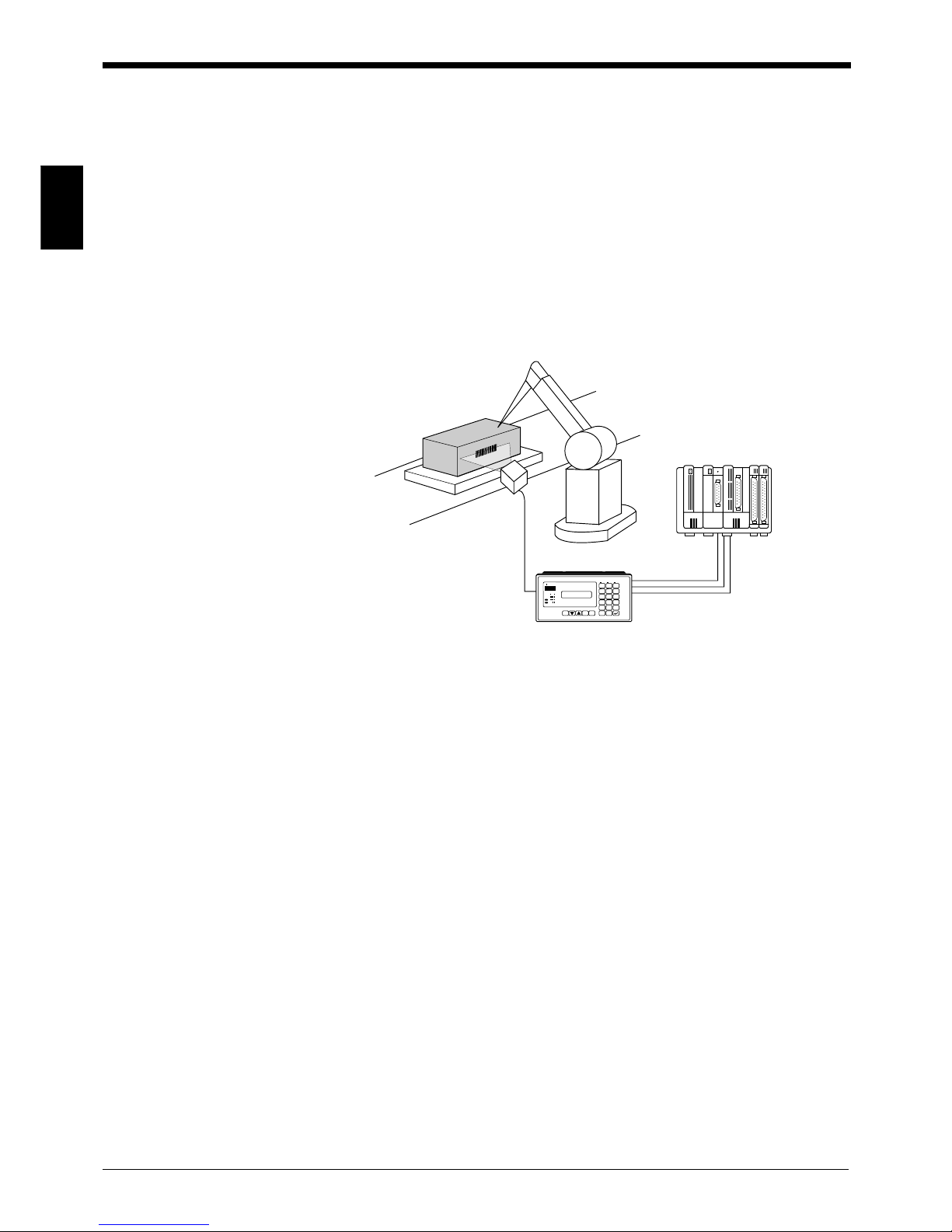
■ BL-V35E
The BL-V35E bar code data verifier stores (presets) up to 399 types of bar code
data, and compares them to the bar code data read by a bar code reader connected to the BL-V35E. When the readout data matches the preset data, the BLV35E outputs the output No. assigned to the matching preset data using a bit,
binary value or BCD number from the parallel port.
The figure below shows the operation of the BL-V35E.
The following bar code reader models can be connected.
■ Fixed-mount type bar code reader
BL-600 series
BL-700 series
BL-500 series
BL-180 series
Bar code readers manufactured by other companies can also be connected.
Terms
The following terms are used throughout this manual.
Bar code
reader
RS-232C
teserPteserP
teserP
teserPteserP
.oN
teserPteserP
teserP
teserPteserP
atad
tuptuOtuptuO
tuptuO
tuptuOtuptuO
.oN
1*BA*1
2 *DC* 2
3*01*3
•
•
•
•
•
•
•
•
•
993*05*993
➪
BL-V35E
Readout data
Comparison
*CD*
External
device
Parallel output
Bit
Binary value
BCD number
➪
➪
➪
mreTnoitpircseD
E53V-LBecafretniyalpsidedocraBE53V-LB
CLP rellortnoccigolelbammargorprofnoitaiverbbA
)CP(retupmoclanosrePenihcamelbitapmocTA/CProCPMBI
redaeredocrabseireSLB
atadedocrabsdaertahttnempiuqE
epyttnuom-dexiffoseires006/007/005/081-LB
ecafretnilaireS E53V-LBehtnidedivorpecafretniC232-SR
ecafretnilellaraPstuptuolatigid21dnastupnilatigid7
iii

How this manual is or ganized
Chapter 1 Overview
This chapter outlines the features and functions of the BL-V35E, the name of each
part, the system configuration and connectable units.
Chapter 2 Setup Procedure
This chapter describes the setting procedure required before the BL-V35E is
connected to a BL series bar code reader, the setting procedure for a BL series bar
code reader connected via the BL-V35E, and the test procedure.
Chapter 3 Wiring and Installation
This chapter describes the specifications of the parallel interface and serial interface of the BL-V35E. This chapter also describes the wiring between the BL-V35E
and various other units.
Chapter 4 Basic Functions
This chapter describes in detail the normal usage and operation of the BL-V35E
such as the multi-preset function and step verification function.
Chapter 5 Extended Functions
This chapter describes useful functions of the BL-V35E such as the data reference
function, digit designation function and parallel output setting function.
Chapter 6 Setting
This chapter describes in detail the setting procedure for each function of the BLV35E, the setting contents and the meaning of the setting parameters.
Chapter 7 Serial Communication
This chapter describes the data send format used when a personal computer is
connected to the serial interface of the BL-V35E. It also describes the command
send/control method.
Chapter 8 PLC Link
This chapter describes the operating procedure and setting procedure used when
the BL-V35E is used in the PLC link.
Chapter 9 Printout Function
This chapter describes how to connect a printer to the BL-V35E, print the readout
bar code data and set the printing parameters.
Appendix
The appendix describes the outer dimensions, factory default settings and BLV35E error screens.
iv

Contents
Chapter 1 Over View
1.1 Confirming the Package Contents ....................................................... 2
1.1.1 BL-V35E package.....................................................................................2
1.2 Overview .................................................................................................4
1.3 Part Names and Functions ....................................................................7
1.4 System Configuration and Connectable Devices ...............................8
1.4.1 Connectable devices.................................................................................8
Chapter 2 Setup Procedure
2.1 Connection and Settings .....................................................................12
2.2 Setting BL Series Bar Code Reader ...................................................14
2.2.1 Changing settings using the setup software ...........................................14
2.2.2 Changing the settings using the BL-P1E (Not available with BL-600)....15
2.3 Using BL Series Bar Code Reader’s Test Mode ...............................17
2.3.1 Sending test mode command from the BL-V35E to the BL series..........17
2.3.2 How to send other commands ................................................................18
Chapter 3 Wiring and Installation
3.1 Mounting ...............................................................................................20
3.2 Connecting the Power Supply ............................................................22
3.2.1 Connecting the power supply..................................................................22
3.3 Wiring the Parallel Interface ................................................................23
3.4 Wiring the Serial Interface ...................................................................25
3.4.1 Pin assignment for serial interface..........................................................25
3.4.2 Connecting a bar code reader ................................................................25
3.4.3 Connecting an external unit ....................................................................27
Chapter 4 Basic Functions
4.1 Multi-preset Function ..........................................................................32
4.1.1 Multi-preset function................................................................................32
4.1.2 Registration of preset data (Preset mode)..............................................32
4.1.3 Registering preset data...........................................................................33
4.1.4 Saving the preset data from any preset No. ...........................................37
4.1.5 Deleting preset data................................................................................38
4.1.6 Preset wildcard function..........................................................................39
4.1.7 Operation (RUN mode)...........................................................................39
4.1.8 Counter function......................................................................................42
4.1.9 Parallel output form.................................................................................45
v

4.2 Preset-active Function ........................................................................46
4.2.1 Preset-active function .............................................................................46
4.2.2 Using the preset-active function..............................................................46
4.2.3 Selecting the preset data to be verified in the preset-active function.....48
4.2.4 Operation using the preset-active function .............................................49
4.3 Step Verification Function ..................................................................50
4.3.1 Step verification function.........................................................................50
4.3.2 Using the step verification function .........................................................50
4.3.3 Operation using the step verification function.........................................51
4.3.4 Parallel output form.................................................................................53
4.4 Serial No. Check Function ..................................................................54
4.4.1 Serial No. check function ........................................................................54
4.4.2 Using the serial No. check function.........................................................54
4.4.3 Setting the parameters of the serial No. check function .........................55
4.4.4 Operation using the serial No. check function ........................................59
4.5 Key Input Procedure ............................................................................61
4.6 Parallel Inputs ......................................................................................64
Chapter 5 Extended Functions
5.1 Data Reference Function .....................................................................66
5.1.1 Data reference function...........................................................................66
5.1.2 Setting procedure for the data reference function...................................66
5.2 Digit Designation Function .................................................................68
5.2.1 Digit designation function ........................................................................68
5.2.2 Setting the digit designation function ......................................................68
5.3 Parallel Output Setting Function ........................................................71
5.3.1 Parallel output setting function................................................................71
5.4 Parallel I/O Direct Control Function ...................................................73
5.4.1 Parallel I/O direct control function ...........................................................73
5.4.2 Directly controlling parallel inputs and outputs........................................73
5.5 Function for Copying Settings between Two BL-V35E Units ..........74
5.5.1 Function for copying settings between two BL-V35E units .....................74
5.5.2 Copying the setting contents between BL-V35E units ............................74
Chapter 6 Setting
6.1 Setting Procedure ................................................................................80
6.1.1 Starting set mode ....................................................................................80
6.1.2 Exiting set mode .....................................................................................82
6.2 Setting Parameters of the BL-V35E ....................................................83
6.2.1 Menu list..................................................................................................83
6.2.2 Communication set mode for serial port 1 ..............................................84
6.2.3 Communication set mode for serial port 2 ..............................................90
6.2.4 Main setting mode...................................................................................91
6.2.5 Option set mode......................................................................................94
6.3 Initialization of Each Setting ...............................................................97
vi

Chapter 7 Serial Communication
7.1 Serial Communication .......................................................................100
7.1.1 Communication format of the BL-V35E ................................................100
7.1.2 Setting the serial communication ..........................................................100
7.2 Details about Data Communication .................................................101
7.2.1 Selecting communication protocols ......................................................101
7.2.2 Capacity of the send buffer ...................................................................102
7.2.3 Send format ..........................................................................................102
7.2.4 Output data type ...................................................................................102
7.2.5 Output data when the step verification function is used........................103
7.2.6 Output data when the serial No. check function is used .......................103
7.3 Details about Command Communication ........................................104
7.3.1 Command communication format .........................................................104
7.3.2 Command list ........................................................................................104
Chapter 8 PLC Link
8.1 PLC Link .............................................................................................112
8.1.1 PLC link.................................................................................................112
8.1.2 List of available PLC units.....................................................................112
8.1.3 Available devices ..................................................................................113
8.2 Setting .................................................................................................114
8.2.1 Settings in the BL-V35E........................................................................114
8.2.2 Settings in the PLC ...............................................................................114
8.3 Assigning Devices .............................................................................116
8.3.1 Data write area......................................................................................116
8.3.2 Detailed description on assignment ......................................................116
8.3.3 Details of assignment when the step verification function is used ........120
8.3.4 Details of assignment when the serial No. check function is used .......120
8.4 PLC Link Error ....................................................................................121
8.4.1 Troubleshooting of PLC link error .........................................................121
8.5 Communication Time ........................................................................122
Chapter 9 Printout Function
9.1 Overview of the Printout Function ...................................................124
9.1.1 Overview of the printout function ..........................................................124
9.1.2 Connection and setting during printout .................................................124
9.2 Automatic Printout Function ............................................................126
9.2.1 Setting the operation of the automatic printout function........................126
9.2.2 Automatic printout when the step verification function is used .............127
9.2.3 Automatic printout when the serial No. check function is used.............128
9.3 Manual Printout Function ..................................................................129
9.3.1 Operation of the manual printout function.............................................129
9.3.2 Performing manual printout...................................................................130
vii

viii
Appendix
Appendix 1. Specifications .........................................................................134
Appendix 2. Dimensions .............................................................................135
Appendix 3. PLC Link Program Examples .................................................136
Appendix 4. Error Display List ....................................................................139
Appendix 5. ASCII Code Table ....................................................................140
Appendix 6. Setting Parameter List ............................................................141
Appendix 7. List of Settings at Shipment ..................................................144
Appendix 8. Index ........................................................................................145

ix

Chapter 1
Overview
This chapter outlines the features and functions of the BL-V35E, the name of each
part, the system configuration and connectable units.
1.1 Confirming the Package Contents ......................................2
1.1.1 BL-V35E package....................................................................2
1.2 Overview ................................................................................4
1.3 Part Names and Functions ..................................................7
1.4 System Configuration and Connectable Devices ..............8
1.4.1 Connectable devices ...............................................................8
Chapter 1 Overview
1
2
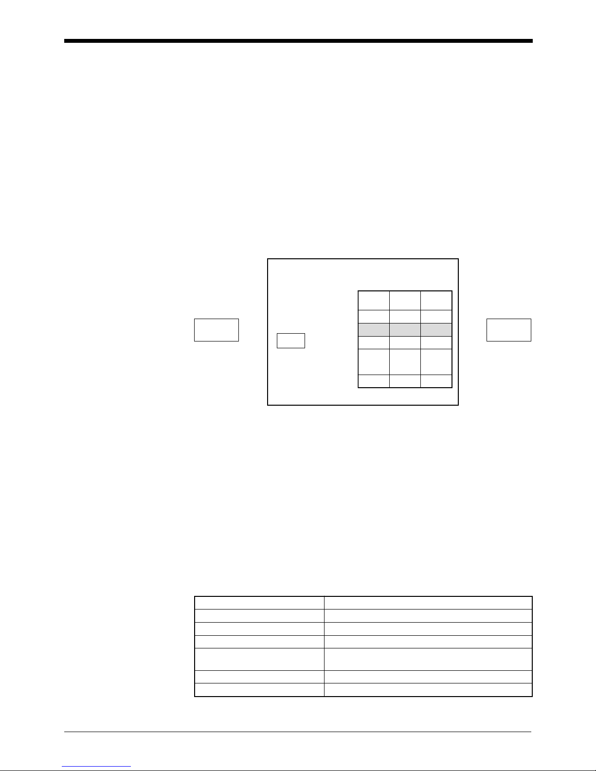
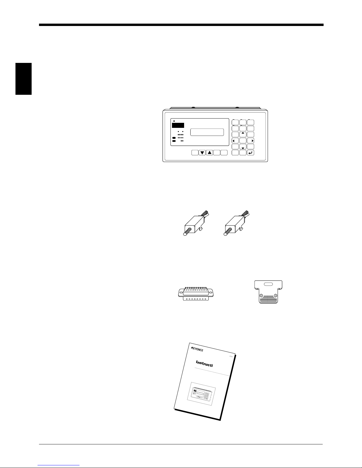
1.1 Confirming the Package Contents
The package contains the following equipment and accessories.
Before using the BL-V35E, make sure that all components have been included.
1.1.1 BL-V35E package
● BL-V35E main unit
● Metal fixture: 2 pieces
● D-sub 25-pin connector and connector case
● Instruction manual (this manual)
PRESET
TIM 2TIM 1
1234
5678
9
10
OUT
OK
NG
PRESET CANCEL ENTER
PRESET
NO.
DATA COUNT
SHIFT
SYMBOL
OPTION
BACK
SPACE
789
456
123
0
CLEAR
MONITORPROGRAM
KEYENCE
BL-V35E
;;;
;;;
Instruction
Manual
B
ar C
o
d
e D
isp
lay In
ter
face
BL-V35E
P
R
E
S
E
T
T
I
M
2
T
I
M
1
1
2
3
4
5
6
7
8
9
1
0
O
U
T
O
K
N
G
P
R
E
S
E
T
C
A
N
C
E
L
E
N
T
E
R
P
R
E
S
E
T
N
o
.
D
A
T
A
C
O
U
N
T
S
H
I
F
T
S
Y
M
B
O
L
O
P
T
I
O
N
B
A
C
K
S
P
A
C
E
789
456
123
0
C
L
E
A
R
M
O
N
I
T
O
R
P
R
O
G
R
A
M
K
E
Y
E
N
C
E
B
L
V
3
5
E
A
5
8
-
0
1
9
Chapter 1 Overview
1
3
● Shift key function description label
It is recommended that you adhere the label to allow smooth operation of the shift
key.
PRESET
1234
1234
5678
9
10
5
IN
OUT
OK
NG
PRESET CANCEL ENTER
PRESET
No.
DATA COUNT
SHIFT
SYMBOL
OPTION
BACK
SPACE
789
456
123
0
CLEAR
KEYENCE
LON
LOFF
SHIFT
SHIFT
#TEST1
#QUIT
TEST1
TEST2
QUIT
SHIFT
SHIFT
SHIFT
SHIFT
SHIFT
4
7
5
8
6
9
3
LON
LOFF
SHIFT
SHIFT
#TEST1
#QUIT
TEST1
TEST2
QUIT
SHIFT
SHIFT
SHIFT
SHIFT
SHIFT
4
7
5
8
6
9
3
BL-V35E
Attach the label here.
Chapter 1 Overview
1
4
1.2 Overview
This section provides an overview of the functions of the BL-V35E.
■ Multi-preset function
The preset function compares the data registered in advance (preset data) to the
readout bar code data. It then produces outputs to indicate whether or not the
readout data matches one of the data presets.
The BL-V35E stores up to 399 data presets and compares them to the readout bar
code data. When the readout data matches the preset data, the BL-V35E outputs
the number assigned to the preset data using a bit, binary value, or BCD number
from the parallel port. These outputs can be used to control robotic operation in
automatic assembly lines or to sort products on conveyor lines.
The following 3 methods can be used to register preset data in the BL-V35E.
• By reading a bar code using a bar code reader
• Key entry
• Serial command
■ Preset-active function
The preset-active function compares a single data preset (up to 399 presets can be
saved) to the readout bar code data. It then produces an OK or NG output to
indicate whether or not the readout data matches the specified preset data. These
outputs can be used to prevent different products from being intermixed during
changeovers.
BL-V35E
PRESET
TIM 2TIM 1
1234
5678
9
10
OUT
OK
NG
PRESET CANCEL ENTER
PRESET
No.
DATA COUNT
SHIFT
ABC..
OPTION
BACK
SPACE
789
456
123
0
CLEAR
MONITORPROGRAM
KEYENCE
BL-V35E
1
2
3
4
5
6
7
8
Bar code
reader
(Comparison/verification)
Parallel output
PLC to control robots
Chapter 1 Overview
1
5
■ Step verification function
The step verification function compares the first data read (first readout data) to the
next data read (second readout data). It then produces outputs to indicate whether
or not the first readout data matches the second readout data.
These outputs can be used to check whether a slip matches an actual product.
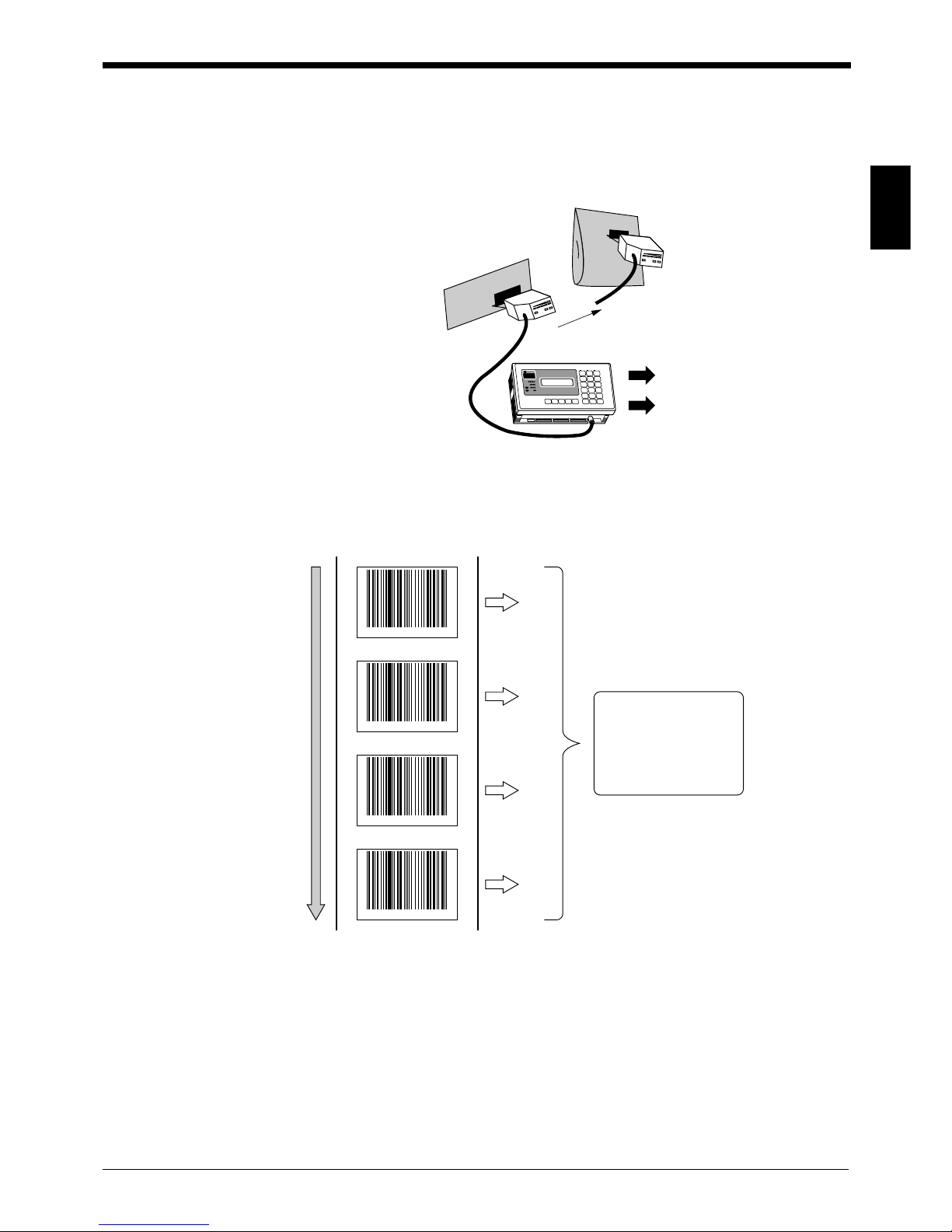
■ Serial No. check function
The serial No. check function checks whether bar code labels are printed using
serial Nos. This function can be used to check whether or not the serial Nos. of
products are printed correctly.
OK output
NG output
OK
* 001 *
NG
* 005 *
OK
* 002 *
OK
* 003 *
OK is output when
consecutive bar code
data is serial.
NG is output when bar
code data is not serial.

Chapter 1 Overview
1
6
■ Printout function
When the serial printer DPU-414 manufactured by SEIKO Instruments Inc. is
connected to the BL-V35E, data can be printed out. Automatic printout and manual
printout are available as printout methods.
● Automatic printout
When a serial printer is connected, the bar code data can be automatically printed
out as soon as the bar code data is read (or the [ENTER] key is pressed).
This method is useful for recording historical data.
● Manual printout
Bar code data can be printed out at any time using the specified key operation.
When this method is used together with the counter function, data on the number
of shipped products can be printed out for each product model.
■ PLC link function
By using the PLC link, the data read by a bar code reader connected to the BLV35E can be written directly to the memory (D area or DM area) inside a programmable logic controller (PLC). When this function is used, communication programs
are not required and the program creation process can be reduced.
■ Data reference function (Ref data)
Normally, data that is read using the connected bar code reader is displayed as is
on the LCD display. The data reference function replaces bar code data with more
meaningful data that is entered in advance using letters, numbers, and symbols.
■ Alternative reading/input available
When the connected stationary bar code reader fails to read a bar code, the
handheld bar code reader that is connected to the other serial interface can read
the bar code instead. The bar code data can also be entered using the BL-V35E’s
panel keys.
PRESET
1234
1234
5678
9
10
5
IN
OUT
OK
NG
PRESET CANCEL ENTER
PRESET
No.
DATA COUNT
SHIFT
SYMBOL
OPTION
BACK
SPACE
789
456
123
0
Chocolate
Chocolate
Caramel
No.000 (NG) Count= 4
(preset NG)
No.001 (001) Count= 1
KEYENCE001
No.002 (001) Count= 1
KEYENCE002
No.003 (003) Count= 21
KEYENCE003
No.004 (004) Count= 2
KEYENCE004
Chapter 1 Overview
1
7
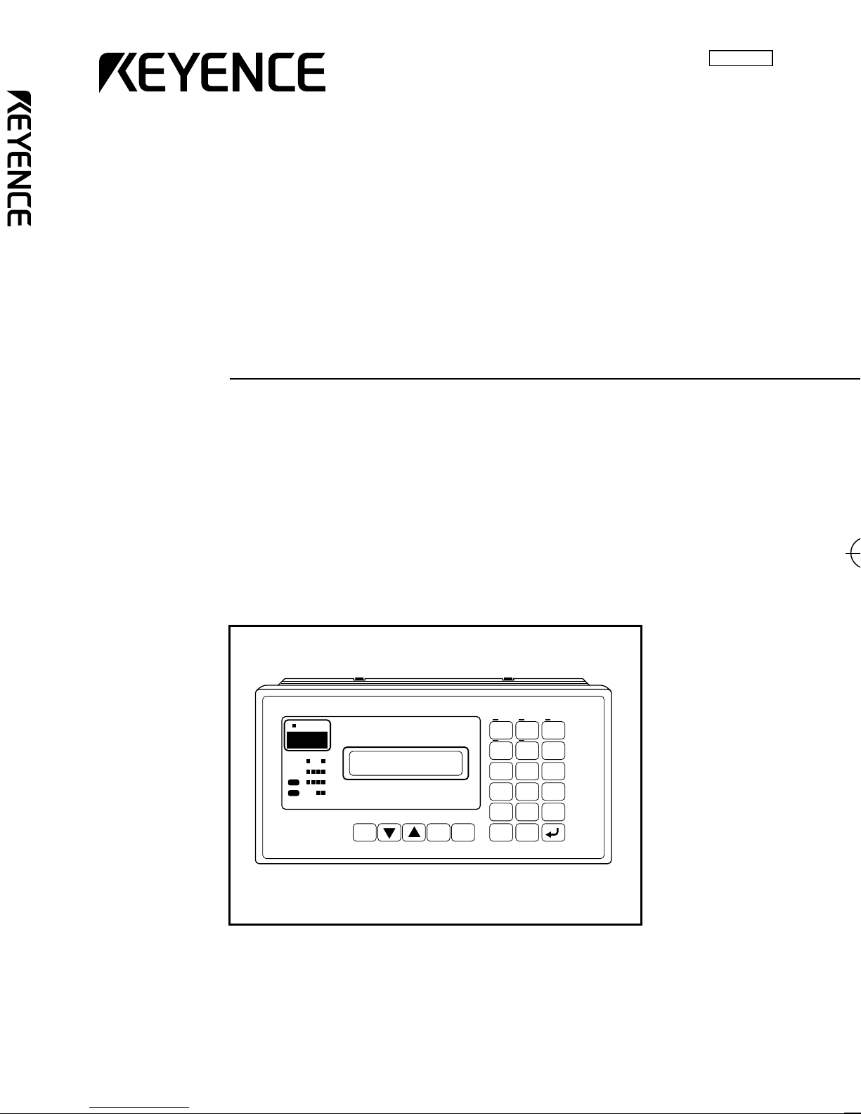
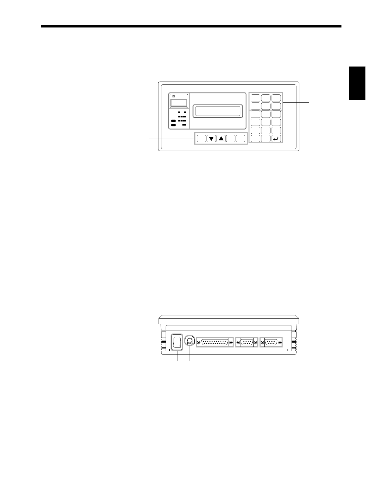
1.3 Part Names and Functions
This section describes the name and function of each part of the BL-V35E.
■ Top panel
1. Preset LED
Illuminated in preset mode.
2. Preset No. indication LED
Indicates that a preset No. is being saved or a preset No. is matching by verification.
3. Parallel I/O LEDs
Indicate the ON/OFF status of each parallel input and output.
4. Main keys
Allow you to enter or change the settings of the preset data.
5. LCD display
Displays the readout bar code data and the parameter to be changed.
6. Data manipulation keys
Allow you to manipulate the data.
The LED above each key is illuminated while the corresponding key is in effect.
7. Numeric keypad
Allows you to enter the data directly.
■ Rear panel
8. POWER switch
Turns on and off the main power supply.
9. 100-120 VAC cable
AC power cable.
10.PARALLEL interface
Provides parallel I/O terminals.
Connects trigger inputs for a connected BL series bar code reader.
11.Serial interface port 1 (PORT 1)
Connects a personal computer, PLC or printer.
12.Serial interface port 2 (PORT 2)
Connects a bar code reader.
6
7
1
2
TIM 2TIM 1
1234
5678
9
10
OUT
OK
NG
PRESET CANCEL ENTER
PRESET
No.
DATA COUNT
SHIFT
SYMBOL
OPTION
BACK
SPACE
789
456
123
0
CLEAR
MONITORPROGRAM
KEYENCE BL-V35E
4
5
3
POWER 100-120 V AC PARALLEL PORT 1 PORT 2(READER)
98 11 1210
Chapter 1 Overview
1
8
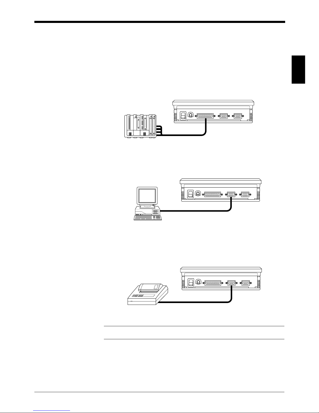
1.4 System Configuration and Connectable Devices
The BL-V35E can be connected to the following devices.
1.4.1 Connectable devices
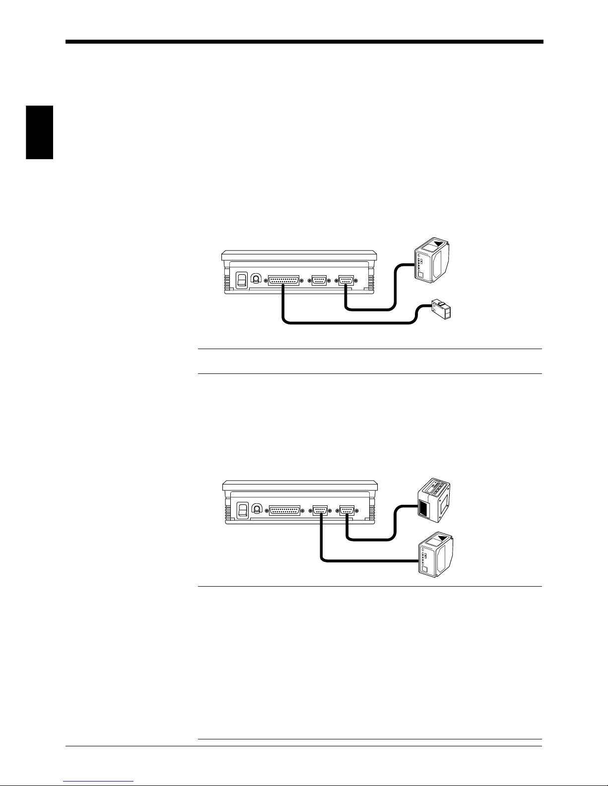
Bar code reader
Connect a bar code reader to serial port 2 (PORT 2).
If you change the settings of the BL-V35E, a bar code reader can be connected to
serial port 1. However, serial port 2 should be used under normal conditions.
● BL series
Connect the BL series directly to serial port 2 (PORT 2). To use a trigger input,
connect the sensor to the parallel (PARALLEL) port of the BL-V35E.
Note: For the synchronization sensor, be sure to use a power supply other than
that of the BL-V35E.
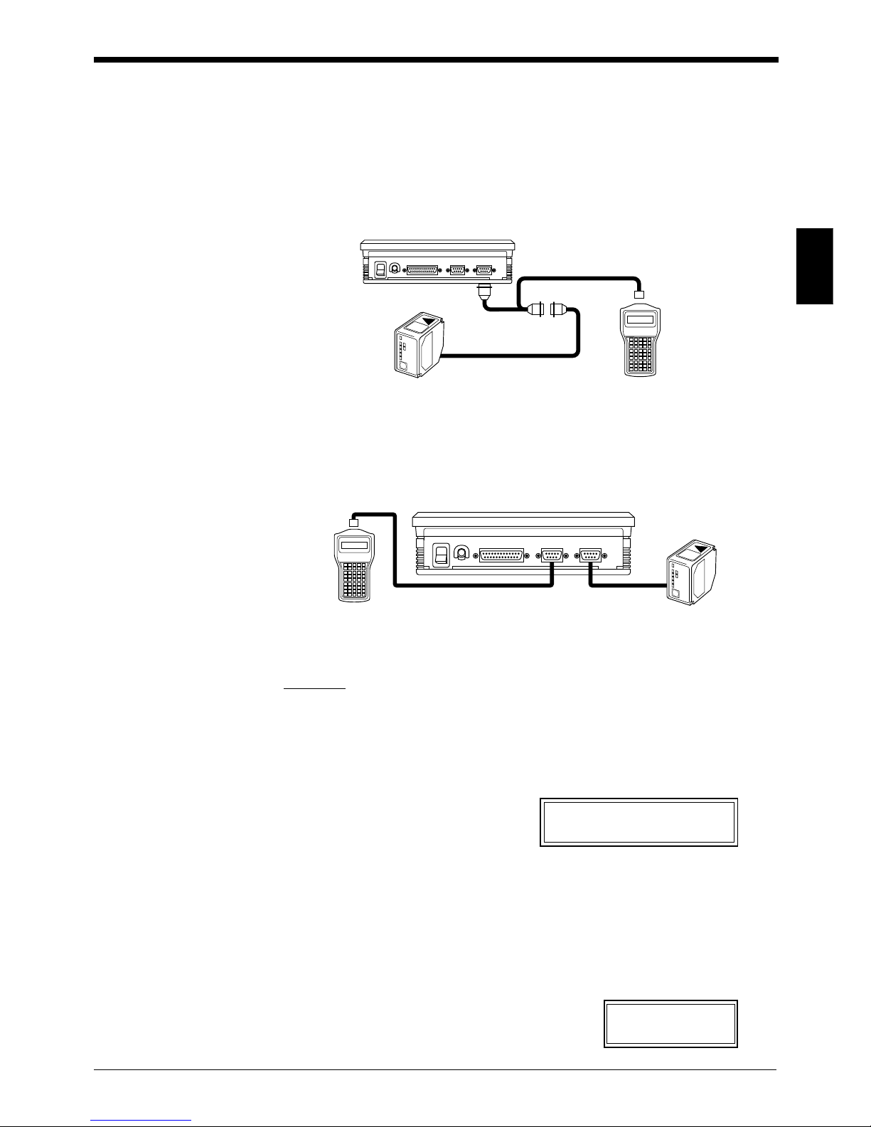
● When using two bar code readers
When serial port 1 (PORT 1) is set to “connection of bar code reader”, two bar
code readers can be connected to the BL-V35E. However, because both PORT 1
and PORT 2 are used in this case, you cannot connect a personal computer, PLC
or printer to the BL-V35E.
When a handheld type bar code reader is connected to PORT 1, it can be used for
alternate readout (
➮
See p. 6
).
Note: The capacity of the 5 VDC power supply supplied from the BL-V35E to the
bar code readers is 750 mA maximum including PORT 1 and PORT 2. Ensure that
the current consumption of all connected bar code readers does not exceed 750
mA. The current consumption of each bar code reader connected directly is as
follows.
BL-600 series: 330 mA or less
BL-180 series: 300 mA or less
BL-500 series: 320 mA or less
BL-500H series: 340 mA or less
BL-700 series: 510 mA or less
BL-P1E: 120 mA or less
The BL-V35E cannot distinguish the data read by a bar code reader connected to
PORT 1 from the data read by a bar code reader connected to PORT 2.
BL series
POWER 100-120 V AC PARALLEL PORT 1 PORT 2 (READER)
Sensor for synchronization
* See Note.
POWER 100-120 V AC PARALLEL PORT 1 PORT 2 (READER)
Chapter 1 Overview
1
9
External devices
The BL-V35E features two output ports to connect external devices: a parallel
output (PARALLEL) port and a serial output (PORT 1) port. The following devices
can be connected to each port. The parallel and serial ports can be used simultaneously.
● Parallel output
The BL-V35E compares the preset data to the readout bar code data. When the
readout data matches the preset data, the BL-V35E outputs the preset number
assigned to the preset data from the parallel port. Connect a PLC or a lamp to the
parallel port.
● Personal computer, PLC (Serial output)
Connect a personal computer or a PLC to serial port 1 (PORT 1), in order to send
the data as is that is read using the bar code reader.
● Printer (serial output)
Connect a printer to serial port 1 (PORT 1). Using this connection, the readout
historical data can be recorded (automatic printout) and the number of shipped
products can be printed out for each product model (manual printout).
Note: A printer and personal computer (or PLC) cannot both be connected to the
BL-V35E at the same time.
POWER 100-120 V AC PARALLEL PORT 1 PORT 2 (READER)
POWER 100-120 V AC PARALLEL PORT 1 PORT 2 (READER)
KV series
POWER 100-120V AC PARALLEL PORT 1 PORT 1 (READER)
Printer
Chapter 1 Overview
1
10
● Direct communication (serial output)
When direct communication is selected (
➮
See p. 89
), the BL-V35E performs the
following operation.
• The readout data is not compared to the preset data. (A parallel output is not
provided.)
• All commands sent from serial port 1 (PORT 1) are sent to a bar code reader
connected to serial port 2 (PORT 2). Commands for the BL-V35E cannot be
accepted.
• All data read by a bar code reader is sent to a personal computer connected to
serial port 1 (PORT 1).
• The readout bar code data is displayed on the BL-V35E. Responses from a BL
series bar code reader to sent commands are also displayed.
• A PLC link is not available.
As described above, when direct communication is selected, a personal computer
connected to serial port 1 communicates with a BL series bar code reader connected to serial port 2 on a one-to-one basis. In this case, the BL-V35E can be
used as a power supply unit equipped with an LCD display. Use direct communication only when commands are to be sent to a BL series bar code reader.
Note: In direct communication, the following constraint is imposed.
The format of a command sent to a BL series bar code reader is fixed as follows.
Command CR
The format of data read by a BL series bar code reader is fixed as follows.
Readout data CR
The “ACK/NAK protocol” and “RTS/CTS protocol” are not available with a BL series
bar code reader. The “PASS/RTRY protocol” is available.
POWER 100-120 V AC PARALLEL PORT 1 PORT 1 (READER)
Personal computer
BL series bar
code reader

Chapter 2
Setup Procedure
This chapter describes the setting procedure required before the BL-V35E is
connected to a BL series bar code reader, the setting procedure for a BL series bar
code reader connected via the BL-V35E, and the test procedure.
2.1 Connection and Settings ...................................................12
2.2 Setting BL Series Bar Code Reader ..................................14
2.2.1 Changing settings using the setup software..........................14
2.2.2 Changing the settings using the BL-P1E
(Not available with BL-600)................................................15
2.3 Using BL Series Bar Code Reader’s Test Mode ..............17
2.3.1 Sending test mode command from the BL-V35E to
the BL series..........................................................................17
2.3.2 How to send other commands ...............................................18
Chapter 2 Setup Procedure
2
12
2.1 Connection and Settings
This section describes the preparations required before using the BL-V35E.
■ Preparations required before using the BL-V35E
Procedure
1. Change the communication parameters of the bar code reader as follows.
• Baud rate: 9600 bps
• Data length: 7 bits
• Parity: Even
• Stop bit length: 1 bit
• Data format: Data [CR] or Data [CR] + [LF]
• Communication protocol: No handshaking
• When the BL series is used, the above changes are unnecessary.
Note: If you cannot change the parameters using the bar code reader, use the BL V35E’s "PORT2 MODE SETUP" (
➮
See p.90.
) to change the parameters of the bar
code reader.
2. Connect the bar code reader to serial port 2 (PORT 2) of the BL-V35E. (
➮
See p.25.
)
3. Read a bar code using the connected bar code reader and see if the
readout data is displayed on the BL-V35E’s LCD display.
• With the BL-600/700 series, read a bar code by lightly pressing the test switch
once.
• With the BL-180/500 series, press the following keys.
If the following operation does not turn on the laser, ensure that steps 1 and 2 in
the procedure were performed properly.
SHIFT
SYMBOL
➞ 7 (LON) ➞ Laser turns ON.
SHIFT
SYMBOL
➞ 4 (LOFF) ➞ Laser turns ON.
* The key operations above cause the BL-V35E to send laser ON/OFF com-
mands to the BL-180/500.
4. Change the detailed settings for the bar code reader connected to the BLV35E (type of bar code to be read, etc.).
• With the BL series, use the setup software supplied with each model or the BLP1E handheld programmer.
To use the setup software: See p. 14.
To use the BL-P1E handheld programmer: See p. 15.
PRESET
1234
1234
5678
9
10
5
IN
OUT
OK
NG
PRESET CANCEL ENTER
PRESET
No.
DATA COUNT
SHIFT
SYMBOL
OPTION
BACK
SPACE
789
456
123
0
CLEAR
19731219

Chapter 2 Setup Procedure
2
13
5. Adjust the detailed settings of the BL-V35E according to the application.
• Operation mode (Main setting mode:
➮
See p.92.
)
• External device to be used (
➮
See p. 84.
)
• Registration of preset data (
➮
See p. 33.
)
6. Connect the trigger input.
• When the BL series is used, connect the trigger input to the BL-V35E (
➮
See p.
23
).
7. Connect the parallel output (
➮
See p. 23
).
This connection is required only when the parallel output is used.
8. Connect an external unit (
➮
See p. 27
).
Change the settings for a connected external unit. Changing the settings is not
required when an external unit is not connected.
For the control procedure and the operating procedure of a connected external
unit, refer to the following page.
• Personal computer (serial communication)
➮
p. 99
• PLC (PLC link)
➮
p. 111
• Printer
➮
p. 123
9. Use the BL-V35E, and ensure that it is operating normally.
This completes preparations for using the BL-V35E.

Chapter 2 Setup Procedure
2
14
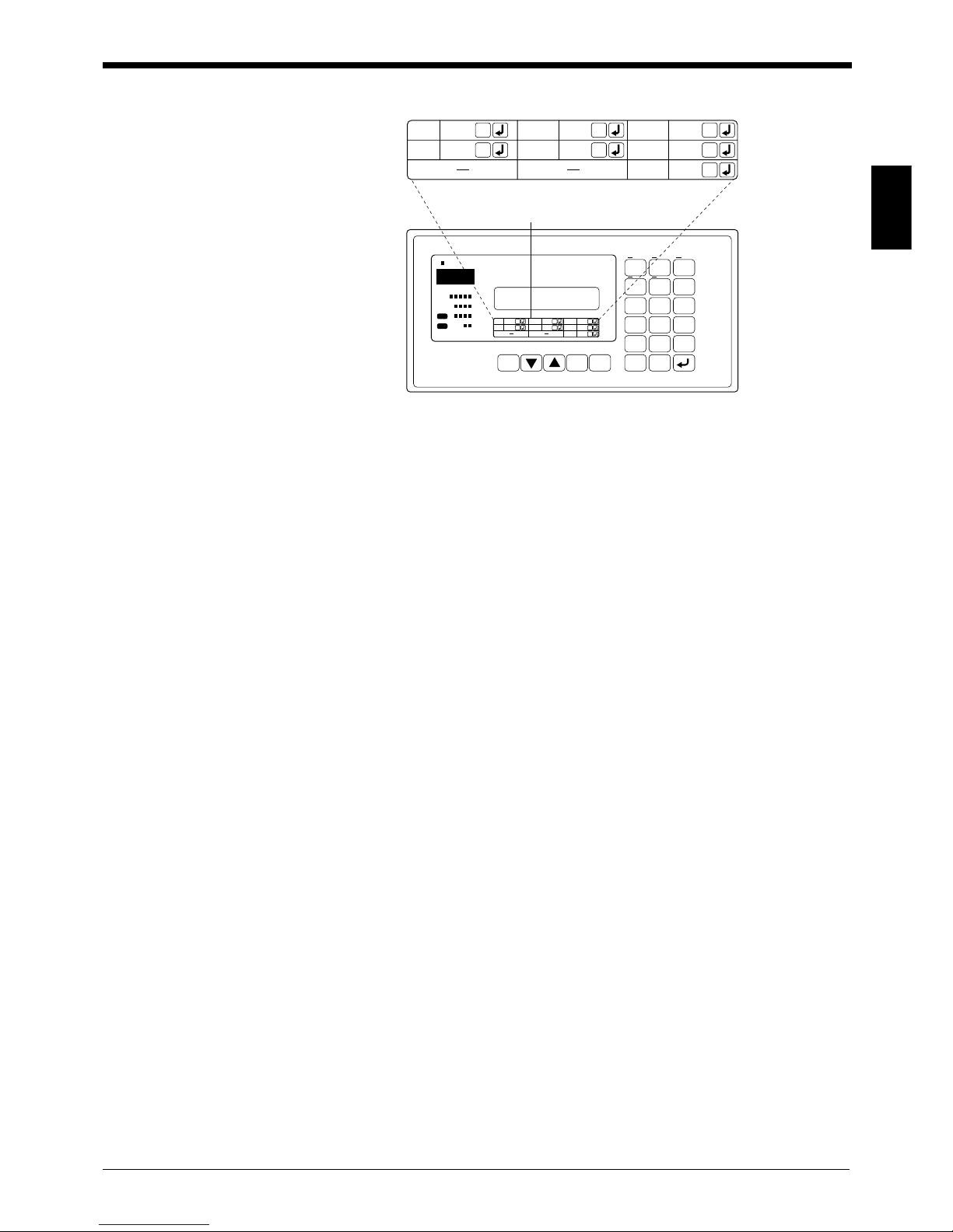
2.2 Setting BL Series Bar Code Reader
To change the settings of the BL series, use the special setup software or the BLP1E handheld programmer. This section describes the setup procedure.
2.2.1 Changing settings using the setup software
This method allows changes to the BL series settings using the setup software by
sending commands via the BL-V35E.
Procedure
1. Follow procedures 1 through 3 in "2.1. Connection and Settings".
2. Connect a personal computer to serial port 1 (PORT 1) of the BL-V35E
using an RS-232C cable. (
➮
See p. 27
)
3. Start the BL setup software. Change the settings of the BL series as
desired.
See the User’s Manual for each model for instructions on how to use the BL
setup software.
Note: Do not change the communication parameters such as baud rate, parity
check, stop bit length, header, terminator, and communication protocol. These
changes disable communication between the personal computer and the BL-V35E.
4. Set the BL-V35E to set mode.
Press and hold the BL-V35E’s [0] key for 2 seconds to enter PROGRAM mode.
The menu shown above appears on the LCD display.
The communication parameters of the BL-V35E’s serial port 1 (PORT 1) are
temporarily set as follows.
• Baud rate: 9600 bps
• Data length: 7 bits
• Parity: Even
• Stop bit length: 1 bit
• Connected device: Personal computer
• Communication protocol: No handshaking
Note: Set mode is also used to change the settings of the BL-V35E itself
(➮
See p. 80
).
5. Send the setting data.
When the BL-V35E shows the display described in step 4, send the settings of
the BL setup software to the connected BL series.
6. Exit set mode.
When the setting data is sent, press the BL-V35E’s [CANCEL] key to exit set
mode.
This completes setup of the BL series using the setup software and the BL-V35E.
1
3) M ain 4)Option
1)Port 2)Port2
Chapter 2 Setup Procedure
2
15
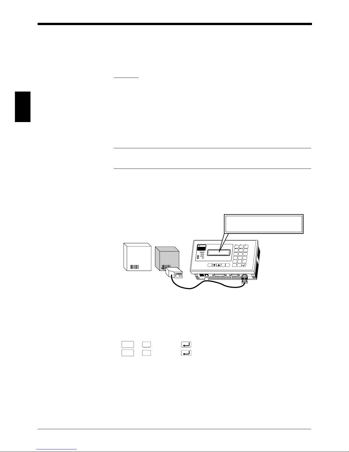
2.2.2 Changing the settings using the BL-P1E (Not available with BL-600)
This procedure allows changes to the settings in the BL series using the BL-P1E
via the BL-V35E. Two connection methods are available.
■ Connecting the BL-P1E using a dedicated cable available as an accessory
of the BL-P1E
Connect the BL-P1E as follows using a dedicated cable available as an accessory
of the BL-P1E.
* For the setting procedure in this case, refer to the BL-P1E User’s Manual.
■ Connecting the BL-P1E using an optional cable
Connect the BL-P1E as follows using an optional cable OP-31097.
Procedure
1. Follow steps 1 through 3 in “2.1 Connection and Settings”.
2. Set the BL-V35E to set mode.
Press and hold the BL-V35E’s [0] key for 2 seconds to enter set mode. The
menu shown below appears on the LCD display.
3. Connect the BL-P1E to serial port 1 (PORT 1) of the BL-V35E as shown in
the figure on the previous page.
4. Change the settings.
Set the slide switch of the BL-P1E to SETUP.
When the menu shown below appears on the LCD display of the BL-P1E,
change the settings while referring to the BL-P1E User’s Manual.
POWER 100-120 V AC PARALLEL PORT 1 PORT 2 (READER)
Dedicated cable: 2 m (available as
an accessory of BL-P1E)
BL series BL-P1E
BL-P1E
POWER 100-120 V AC PARALLEL PORT 1 PORT 2( READER)
Optional cable: 2 m (OP-31097)
BL series
1
3)Main 4)Opt ion
1)Port 2)Port2
Menu
Code1, Code2, Code3

Chapter 2 Setup Procedure
2
16
Note: If the message shown below appears on the LCD display of the BL-P1E
when the BL-P1E is connected, check the connection between the BL-P1E, the BLV35E and the BL series bar code reader. Ensure that the BL-V35E is set to set
mode as described in step 2, and then press the BL-P1E’s [ESC] key.
5. Exit set mode.
When the settings are completed, press the BL-V35E’s [CANCEL] key to exit
set mode. Return the connection to the initial status.
This completes setup of the BL-V35E using the BL-P1E.
Non-connection
Push < ESC > Key
Note: BL-P1E is not available with BL-600.

Chapter 2 Setup Procedure
2
17
2.3 Using BL Series Bar Code Reader’s T est Mode
This section describes how to use the BL-V35E to send test mode commands to
the BL series.
2.3.1 Sending test mode command from the BL-V35E to the BL series
Procedure
1. Set the BL-V35E to monitor mode.
Before entering test mode, press and hold the BL-V35E’s [CLEAR] key for 2
seconds to enter monitor mode.
Note: When test mode starts, a large quantity of data is sent from the BL series bar
code reader to the BL-V35E. The BL-V35E normally compares all received data to
the preset data, and then outputs the results from the parallel port. However, the
operation above prevents the BL-V35E from comparing received data with the
preset data as well as producing the parallel output. Therefore, the reading test
does not affect the operation of the external devices connected to the BL-V35E.
This mode is called monitor mode.
2. Send the test mode command to the BL series bar code reader.
Check the connection between the BL series and serial port 2 of the BL-V35E.
Then, press the following keys.
● Reading rate check mode
SHIFT
SYMBOL
➞ 9 (TEST1)
Reading rate check mode:
The bar code reader scans a bar code 100 times and analyzes how many times
it can decode the scanned data. This mode is used to adjust the reading distance and angle of the bar code reader.
● Tact check mode
SHIFT
SYMBOL
➞6 (TEST2)
Tact check mode:
The bar code reader counts how many scans can be decoded while reading
one bar code. This mode is used for moving bar code labels, in order to determine the line speed that can be expected when the bar code reader is actually
implemented in the line.
3. Read the bar code in the selected test mode.
The readout data and the reading rate (No. of successful readings) are shown
on the LCD display. The monitor indicator on the lower right corner rotates to
indicate that the BL-V35E is receiving data.
Note: If the total of the readout bar code data and the additional data (reading rate,
etc.) exceeds 32 characters, the BL-V35E cannot receive the data. Limit the total
data to be sent to less than 32 characters.
In monitor mode, both the serial and parallel outputs are disabled.
Start
<M modoni tor e>
TEST1
9><Sh i f t
6>
TEST2
<Sh i f t
4:1
/
ABC123 00%
Monitor indicator
Chapter 2 Setup Procedure
2
18
4. Exit test mode.
Press the following keys to exit test mode.
SHIFT
SYMBOL
➞ 3 (QUIT)
5. Exit monitor mode.
Once the BL-V35E exits test mode, press the [CLEAR] key to exit monitor
mode.
This completes test mode operation of the BL series bar code reader.
2.3.2 How to send other commands
In addition to commands for starting up test mode, the following commands can
also be sent using the [SHIFT SYMBOL] key.
•
SHIFT
SYMBOL
➞ 6 ➞ : #TEST1
Starts up on-line test mode (available in the BL-700 series only).
•
SHIFT
SYMBOL
➞ 5 ➞ : #QUIT
Exits on-line test mode (available in the BL-700 series only).
•
SHIFT
SYMBOL
➞ 7 ➞ : LON
Starts readout.
•
SHIFT
SYMBOL
➞ 4 ➞ : LOFF
Finishes readout.
The commands above can be sent even while the BL-V35E is not set to monitor
mode.
QU I T
3><Sh i f t
End
<M modoni tor e>

Chapter 3
Wiring and Installation
This chapter describes the specifications of the parallel interface and serial interface of the BL-V35E. This chapter also describes the wiring between the BL-V35E
and various other units.
3.1 Mounting ..............................................................................20
3.2 Connecting the Power Supply ...........................................22
3.2.1 Connecting the power supply ................................................22
3.3 Wiring the Parallel Interface ..............................................23
3.4 Wiring the Serial Interface .................................................25
3.4.1 Pin assignment for serial interface.........................................25
3.4.2 Connecting a bar code reader ...............................................25
3.4.3 Connecting an external unit ...................................................27
Chapter 3 Wiring and Installation
3
20
3.1 Mounting
This section describes how to mount the BL-V35E.
The BL-V35E can be mounted using either of the following methods.
■ Placement
Place the BL-V35E on a desk, etc.
■ Direct mount
Pull out the metal fixtures for direct mount provided on the bottom of the BL-V35E,
and tighten the fixtures using screws.
■ Mount to panel
For the panel cut dimensions, refer to the outline drawing (
➮
See p. 135
).
Secure the BL-V35E temporarily with 1, and then secure it permanently with 2.
Be sure to tighten the screws by hand. If a tool is used, the case may be
damaged.
(mounting hole)
Bottom
CAUTION
Metal fixture for direct
mount
Fixture for mount to
DIN rail
Rubber pad
Bottom of BL-V35E
Metal fixture for direct
mount
Rubber pad
PRESET
1234
1234
5678
910
5
IN
OUT
OK
NG
PRESET CANCEL ENTER
PRESET
No.
DATA COUNT
ABC.. OPTION
BACK
SPACE
789
456
123
0
CLEAR
150
98
4- ø5
21
 Loading...