

Page 1
96M11830
Wireless
Hand-held Barcode Reader
BL-N90 Series
User's Manual
Read this manual before using the system in order
to achieve maximum performance.
Keep this manual in a safe place after reading it so
that it can be used at any time.
Page 2

Introduction
This manual contains information about procedures for handling, operations, warnings, and
precautions about the "Wireless Hand-held Barcode Reader BL-N90 Series".
Be sure to read this section thoroughly before use. Keep this manual in a safe place for future
reference.
z Symbols
The following symbols and conventions alert you to important messages.
Be sure to read these messages carefully.
DANGER
WARNING
CAUTION
Note
Indicates reference pages in this or another manual.
Failure to follow these instructions may lead to death or serious injury.
Failure to follow instructions may lead to physical injury, such as electric shock
or burns.
Failure to follow instructions may lead to product damage.
Provides additional information on proper operations that can be easily mistaken.
z General Cautions
• At startup and during operation, be sure to monitor the functions and performance of the
BL-N90 Series.
• We recommend that you take substantial safety measures to avoid any damage in the
event of a problem occurring.
• Do not modify the BL-N90 Series, or use it in any way other than described in the
specifications.
• When the BL-N90 Series is used in combination with other devices, functions and
performance may be degraded, depending on the operating conditions and
surrounding environment.
• Do not use the BL-N90 Series for the purpose of protecting the human body.
z Applications that Need Special Attention
When using the BL-N90 Series under the following conditions, be sure to use the BL-N90
Series under the specified rating or within the provided functions, or take sufficient safety
precautions such as providing a failsafe, and consult with KEYENCE sales staff.
• Under the conditions or environment not described in this manual
• For atomic controls, railway facilities, aviation facilities, vehicles, combustion devices,
medical equipment, amusement machines, or safety equipment
• For the applications that may affect human life or properties and particularly require
safety
Page 3

Laser Safety Precautions
Model BL-N90
Wavelength 650 nm
Maximum output 350 μW
Laser Class
* The classification is implemented based on IEC60825-1 following the requirements of
Laser Notice No.50 of FDA (CDRH).
Use of controls or adjustments or performance of procedures other than
•
those specified herein may result in hazardous radiation exposure.
• Do not look directly at laser light or reflected laser light from a mirrored
surface. Otherwise, e ye injury ma y result. Laser ligh t will not cause damage if
it strikes exposed skin, but laser light should not deliberately be aimed
towards a human body.
• Do not disassemble the BL-N90 Series. The BL-N90 Series does not
automatically stop emitting the laser when the reader is disassembled.
CAUTION
Therefore, if someone disassemb les the reader, he/she may be exposed to
the laser beam and may suffer eye injury.
• Be sure to stop the laser emission before cleaning the portion of the laser
scanner where laser light is generated and received (transmitter/receiver).
Otherwise, exposure to the laser may cause eye injury.
• Be careful of the path of the laser beam.
Be especially careful of reflected laser light from a mirrored surface.
Do not use the BL-N90 Series where the path of the laser beam is at the
same height as that of the human eye.
Class1 Laser Product (IEC60825-1)
Class Laser Product (FDA (CDRH) Part1040.10)
96M11830
1
Page 4

Precautions on Using the Built-in Rechargeable Battery
BL-N90 has a built-in lithium ion rechargeable battery. Pay attention to the following
precautions and use the reader correctly.
When disposing of the reader, following the disposal procedures prescribed by the local
government.
If the battery has not completed charging even after the prescribed charging
•
time has passed, stop attempting to charge the battery. Otherwise, heat
generation, explosion, or fire may occur from built-in rechargeable battery.
• Immediately remove the built-in rechargeable battery from nearby flames if
DANGER
WARNING
leaks or strange smells are foun d. Leakin g battery electrolytes a re flammable
and may cause explosion or fire.
• If the built-in recharg eable battery is placed into a fire, it may explode and
cause a severe accident. Do not place the rechargeable battery in a fire.
• If the built-in rechargeab le battery is placed in water , it ma y cause an accident
due to chemical reactions. Do not place the rechargeable batter in water.
•
If liquid leaking from the built-in rechargeable batt ery comes into contact with
the eyes, refrain from rubbin g the e yes . Immediately fl ush the e yes wi th water
and seek medical treatment. F ailure to treat the problem may lea d to eye
damage.
• If liquid leaking from the buil t-in rechargeable batter comes into contact with
skin, immediately wash the area with water. Failure to do so may cause a
rash.
•
Do not store or use the BL-N90 Series in locations that reach high
temperatures, such as within a high-temperature vehicle or outside in direct
sunlight. This may lead to heat or fire from the built-in rechargeable battery,
as well as a reduction in battery life or performance.
CAUTION
• Use and charge the built-in rechargeable battery in conditions where the
temperature is 0 to +40°C. Using or charging the built-in rechargeable batter
in higher temperatures may lead to heat or fire from the battery, as well as a
reduction in battery life or performance.
• Do not use a device other than the dedicat ed charger to charge the battery.
Otherwise, it may cause malfunctions.
2
Page 5
Handling the BL-N90
When recharging the BL-N90 with BL-N9R, BL-N9UB, or B L-N9V, make sure
•
to check whether foreign materials have entered the charging terminal. The
presence of foreign materials may generate high heat or ignition, which may
cause fires.
• Check whether dust co v ers the po we r plug of the A C adapt er that connects to
WARNING
CAUTION
BL-N9R, BL-N9UB, or BL-N9V, and clean it regularly. The re is a danger that a
fire will start due to tracking. Also, remove the plug from the electrical outlet
when not using the BL-N90 Series for a long period of time.
• Always use the included AC adapter with BL-N9R, BL-N9UB, or BL-N9V.
Using another AC adapter may cause fire, electrical shock, or damage to the
equipment.
•
Do not modify or disassemble the BL-N90 Ser i es. Doin g so may cause damage.
• The BL-N90 Series is a precision instrument. Dropping it or applying strong
shock may cause damage to the instrument. Take appropriate precautions
when transporting the BL-N90 Series.
• Do not place the BL-N90 Series in locations with large amounts of moistu re or
dust. Also, do not leave small metallic objects, such as paperclips, near the
instrument. Doing so may cause fire or damage.
• Do not use the BL-N90 Series in the following locations. Usage in these
locations may cause damage or malfunctions.
– Locations where the ambient temperature exceeds the rated range.
– Locations where the ambient humidity exceeds the rated range.
– Locations exposed to direct sunlight.
– Locations where temperatures may increase grea tly, such as within a
vehicle with the windows closed.
– Locations where sharp temperature changes may cause condensation.
– Locations with corrosive or flammable gases.
– Locations with a large amount of dust, salt, iron, or greasy fumes .
– Locations that are directly affected by vibrations or shock.
– Locations where the unit may be splashed by water, oil, or chemicals .
– Locations with strong magnetic or electrical fields.
z Notes about the default number of digits for reading
The number of digits of barcode for reading is set to three digits or more by default to
prevent misreading.
How to count the digits varies depending on the barcode type, but the minimum number
of digits for reading by default is as follows.
Barcode type Example of barcode with three digits or more
CODE39 *123*
Codabar (NW-7) A1A
ITF 1234
CODE128 123
If you read a barcode with less than three digits, change the setting with the Limit read
digits function.
3
Page 6

Wireless Communication
2.4 FH 1
The BL-N90 Series contains an internal wireless function based on Bluetooth wireless
technology.
z Precautions for wireless communication
• Using the BL-N90 Series near wireless LAN equipment that operates in the same
frequency band may cause radio interference, reduce the communication speed, and
make communication impossible.
• Using the BL-N90 Series near equipment that operates in the same frequency band,
such as microwave ovens, industrial heaters, or high frequency medical equipment,
may make communication impossible.
• The BL-N90 Series may not be able to communicate in the following types of locations.
– Locations close to metallic substances or with large amounts of metallic powder
– Locations surrounded by metallic walls
– Locations that are subject to strong vibrations
• The guideline for communication distance is a visible range of about 10 m, but there are
some environments where communication is not possible even within this range. Make
sure to check communication before installation.
2.4 : Indicates that the wireless device is used
in a 2.4 GHz band.
FH :
Indicates that the modulation system is FH-SS.
1:
Indicates the estimated interference distance (10 m).
:
Indicates that the equipment uses the full
bandwidth and identification of moving
object equipment area cannot be avoided.
4
Page 7

Precautions on Regulations and Standards
■ Europe
z Precautions on CE Marking
The BL-N90 Series conforms to the R&TTE Directive requirements.
• Applicable standard ESTI EN300 328 V1.6.1
ESTI EN301 489-17 V1.2.1
EN60950-1
EN60825-1, Laser Class 1
• Overvoltage category I (BL-N90)
II (BL-N9R/N9UB/N9V)
• Pollution degree 2
z Countries where the BL-N90 Series can be used
Among the EU member states, the BL-N90 Series can be used in the following countries.
{ Austria { Belgium { Cyprus { Czech Republic
{ Denmark { Estonia { Finland { France
{ Germany { Greece { Hungary { Ireland
{ Italy { Latvia { Lithuania { Luxemburg
{ Malta { Netherlands { Poland { Portugal
{ Slovakia { Slovenia { Spain { Sweden
{ U.K.
5
Page 8

■ North America
z Precautions on FCC
The BL-N90 Series conforms to the following FCC regulations.
• Applicable standard FCC Part 15 Subpart B, Class B Digital Device
FCC Part 15 Subpart C
• FCC ID RF40823A (BL-N90)
RF40823B (BL-N9R/N9UB/N9V)
FCC WARNING
Changes or modifications not expressly apprvoed by the party responsible for
compliance could void the user's authority to operate the equipment.This device complies
with Part 15 of the FCC Rules and RSS-Gen of the IC Rules. Operation is subject to the
following two conditions:
(1) this device may not cause harmful interference, and (2) this device must accept any
interference received, including interference that may cause undesired operation.
NOTICE
• The BL-N90 and the BL-N9R/N9UB/N9V have been tested and found to comply with the
limits for a Class B digital device, pursuant to part 15 of the FCC Rules. These limits are
designed to provide reasonable protection against harmful interference in a residential
installation. The BL-N90 and the BL-N9R/N9UB/N9V generate, use and can radiate
radio frequency energy and, if not installed and used in accordance with the
instructions, may cause harmful interference to radio communications. However, there is
no guarantee that interference will not occur in a particular installation. If the BL-N90 and
the BL-N9R/N9UB/N9V do cause harmful interference to radio or television reception,
which can be determined by turning the equipment off and on, the user is encouraged
to try to correct the interference by one or more of the following measures:
– Reorient or relocate the receiving antenna
– Increase the separation between the equipment and receiver.
– Connect the equipment into an outlet on a circuit different from that to which the
receiver is connected.
– Consult the dealer or an experienced radio/TV technician for help.
The BL-N9R/N9UB/N9V complies with FCC radiation exposure limits set forth for
uncontrolled equipment and meets the FCC radio frequency (RF) Exposure Guidelines in
Supplement C to OET65. The BL-N9R/N9UB/N9V has very low levels of RF energy that it
deemed to comply without maximum permissive exposure evaluation (MPE). But it is
desirable that it should be installed and operated with at least 20cm and more between
the radiator and person's body (excluding extremities: hands, wrists, feet and legs).
The BL-N90 complies with FCC radiation exposure limits set forth for uncontrolled
equipment and meets the FCC radio frequency (RF) Exposure Guidelines in Supplement
C to OET65. The BL-N90 has very low levels of RF energy that it is deemed to comply
without testing of specific absorption ratio (SAR).
6
Page 9

z Precautions on UL and CSA
The BL-N90 Series complies with the following UL and CSA standards. The equipment
has received UL and C-UL certification.
• Applicable standard UL60950-1
CAN/CSA C22.2 No.60950-1-03
• UL File No. E167973
• UL category NWGQ/NWGQ7
• Pollution degree 2
• Overvoltage category I (BL-N90)
II (BL-N9R/N9UB/N9V)
Be sure to use the power supply that has the Class 2 output specified by NEPA70 (NEC:
National Electric Code).
z Precautions on IC (Industry Canada) standards
The BL-N90 Series complies with the following radio and electromagnetic wave
standards. The equipment has received the recognition of these standards.
• Applicable standards RSS-210-Low Power License-Exempt Radio Communication
Devices
ICES-003, Issue 4, Class B Digital Apparatus
• IC No. 5798A-0823A (BL-N90)
5798A-0823B (BL-N9R/N9UB/N9V)
7
Page 10

Maintenance
Charging terminals
Transmitter/
receiver
Charging terminals
Clean the following parts on the BL-N90 and the communication unit periodically.
• BL-N90
Clean the laser transmitter/receiver and the charging terminals.
• Communication unit
Clean the charging terminals.
z Cleaning method
Transmitter/receiver : Clean the surface using an eyeglass cleaning cloth or a soft cloth
that has been dampened with a specialty cleaner for plastics.
Charging terminals : Wipe the surface gently using a soft cloth moistened with alcohol.
8
Page 11

Table of Contents
Introduction
Laser Safety Precautions . . . . . . . . . . . . . . . . . . . . . . . . . . . . . . . . . . . 1
Precautions on Using the Built-in Rechargeable Battery . . . . . . . . . . .2
Handling the BL-N90. . . . . . . . . . . . . . . . . . . . . . . . . . . . . . . . . . . . . . . 3
Wireless Communication . . . . . . . . . . . . . . . . . . . . . . . . . . . . . . . . . . .4
Precautions on Regulations and Standards . . . . . . . . . . . . . . . . . . . . .5
Maintenance . . . . . . . . . . . . . . . . . . . . . . . . . . . . . . . . . . . . . . . . . . . . .8
Table of Contents . . . . . . . . . . . . . . . . . . . . . . . . . . . . . . . . . . . . . . . . . 9
Chapter 1 Overview
1-1 Checking the Package Contents . . . . . . . . . . . . . . . . . . . . . . 1-2
1-2 Part Names. . . . . . . . . . . . . . . . . . . . . . . . . . . . . . . . . . . . . . . 1-5
Operation Check LED. . . . . . . . . . . . . . . . . . . . . . . . . . . . . . . 1-6
Chapter 2 Initial Setup
2-1 Initial Setup. . . . . . . . . . . . . . . . . . . . . . . . . . . . . . . . . . . . . . . 2-2
2-2 Connecting the Power Cable to the Communication Unit. . . . 2-3
2-3 Connecting the Communication Unit . . . . . . . . . . . . . . . . . . . 2-5
Connecting the BL-N9UB to the Computer . . . . . . . . . . . . . . 2-5
Connecting the BL-N9V to the Computer. . . . . . . . . . . . . . . . 2-7
Connecting the BL-N9R to the Computer. . . . . . . . . . . . . . . . 2-9
2-4 Charging the BL-N90 . . . . . . . . . . . . . . . . . . . . . . . . . . . . . . 2-11
Rechargeable Batteries for the BL-N90 . . . . . . . . . . . . . . . . 2-12
2-5 Establishing a Connection . . . . . . . . . . . . . . . . . . . . . . . . . . 2-13
Notes for Establishing a Connection . . . . . . . . . . . . . . . . . . 2-14
2-6 Initializing the BL-N90. . . . . . . . . . . . . . . . . . . . . . . . . . . . . . 2-15
2-7 Reading a Barcode. . . . . . . . . . . . . . . . . . . . . . . . . . . . . . . . 2-16
Scanning a Barcode . . . . . . . . . . . . . . . . . . . . . . . . . . . . . . . 2-16
2-8 Checking the Connected Pair . . . . . . . . . . . . . . . . . . . . . . . . 2-18
2-9 Wireless Connection Environment . . . . . . . . . . . . . . . . . . . . 2-19
9
Page 12

Chapter 3 Descriptions of Key Functions
3-1 Reading . . . . . . . . . . . . . . . . . . . . . . . . . . . . . . . . . . . . . . . . . 3-2
Functions when Reading the Barcode . . . . . . . . . . . . . . . . . . 3-3
3-2 Selecting the Reading Mode. . . . . . . . . . . . . . . . . . . . . . . . . . 3-5
Selecting the Reading Mode . . . . . . . . . . . . . . . . . . . . . . . . . 3-5
3-3 Sending the Reading Data . . . . . . . . . . . . . . . . . . . . . . . . . . . 3-9
Data Format . . . . . . . . . . . . . . . . . . . . . . . . . . . . . . . . . . . . . . 3-9
Inter-character Delay . . . . . . . . . . . . . . . . . . . . . . . . . . . . . . 3-10
3-4 Settings for Each Communication Interface . . . . . . . . . . . . . 3-11
Keyboard/USB Connection Interface (BL-N9V/N9UB). . . . . 3-11
RS-232C Communication Interface (BL-N9R) . . . . . . . . . . . 3-11
3-5 Charge Error Prevention. . . . . . . . . . . . . . . . . . . . . . . . . . . . 3-13
3-6 Sleep Mode. . . . . . . . . . . . . . . . . . . . . . . . . . . . . . . . . . . . . . 3-14
Chapter 4 Program
4-1 Using the Program Barcode Menu . . . . . . . . . . . . . . . . . . . . . 4-2
Configuring the Program . . . . . . . . . . . . . . . . . . . . . . . . . . . . 4-2
4-2 Starting and Ending the Program . . . . . . . . . . . . . . . . . . . . . . 4-3
Start/End Program . . . . . . . . . . . . . . . . . . . . . . . . . . . . . . . . . 4-3
Initialization . . . . . . . . . . . . . . . . . . . . . . . . . . . . . . . . . . . . . . . 4-3
4-3 Settings for the Barcode Type . . . . . . . . . . . . . . . . . . . . . . . . 4-4
Code Type Settings . . . . . . . . . . . . . . . . . . . . . . . . . . . . . . . . 4-4
EAN/UPC Detailed Settings . . . . . . . . . . . . . . . . . . . . . . . . . . 4-6
CODE128 Detailed Settings . . . . . . . . . . . . . . . . . . . . . . . . . . 4-8
CODE39 Detailed Settings . . . . . . . . . . . . . . . . . . . . . . . . . . . 4-9
Codabar (NW-7) Detailed Settings . . . . . . . . . . . . . . . . . . . . 4-10
ITF Detailed Settings. . . . . . . . . . . . . . . . . . . . . . . . . . . . . . . 4-11
RSS-14 Detailed Settings . . . . . . . . . . . . . . . . . . . . . . . . . . . 4-11
RSS Limited Detailed Settings . . . . . . . . . . . . . . . . . . . . . . . 4-12
RSS Expanded Detailed Settings . . . . . . . . . . . . . . . . . . . . . 4-12
4-4 Setting the Reading Mode . . . . . . . . . . . . . . . . . . . . . . . . . . 4-13
Reading Mode . . . . . . . . . . . . . . . . . . . . . . . . . . . . . . . . . . . 4-13
Reading on the Communication Unit . . . . . . . . . . . . . . . . . . 4-14
4-5 Buzzer Settings. . . . . . . . . . . . . . . . . . . . . . . . . . . . . . . . . . . 4-15
10
Page 13

Tone Selection . . . . . . . . . . . . . . . . . . . . . . . . . . . . . . . . . . . 4-15
4-6 Decode Settings . . . . . . . . . . . . . . . . . . . . . . . . . . . . . . . . . . 4-16
Settings for the Number of Times to Read Matching Barcodes 416
Selecting the Reread Prevention Time . . . . . . . . . . . . . . . . . 4-17
4-7 Settings for Limit Read Digits . . . . . . . . . . . . . . . . . . . . . . . . 4-18
4-8 Communication Data Format Settings . . . . . . . . . . . . . . . . . 4-21
Data Format . . . . . . . . . . . . . . . . . . . . . . . . . . . . . . . . . . . . . 4-21
Inter-character Delay Settings . . . . . . . . . . . . . . . . . . . . . . . 4-22
4-9 Settings for Each Connection Interface . . . . . . . . . . . . . . . . 4-23
Keyboard/USB Settings . . . . . . . . . . . . . . . . . . . . . . . . . . . . 4-23
RS-232C Settings . . . . . . . . . . . . . . . . . . . . . . . . . . . . . . . . . 4-23
4-10 Other Settings. . . . . . . . . . . . . . . . . . . . . . . . . . . . . . . . . . . . 4-25
Charge Error Prevention . . . . . . . . . . . . . . . . . . . . . . . . . . . . 4-25
4-11 Decimal Program Code . . . . . . . . . . . . . . . . . . . . . . . . . . . . 4-26
4-12 Code Type List . . . . . . . . . . . . . . . . . . . . . . . . . . . . . . . . . . . 4-27
Appendices
A-1 Specifications . . . . . . . . . . . . . . . . . . . . . . . . . . . . . . . . . . . . . A-2
A-2 Dimensions. . . . . . . . . . . . . . . . . . . . . . . . . . . . . . . . . . . . . . . A-4
A-3 Using the Wall Mount with the Communication Unit. . . . . . . . A-6
Mounting. . . . . . . . . . . . . . . . . . . . . . . . . . . . . . . . . . . . . . . . . A-6
A-4 Dedicated Stand . . . . . . . . . . . . . . . . . . . . . . . . . . . . . . . . . . . A-9
Checking the Package Contents . . . . . . . . . . . . . . . . . . . . . A-10
Using the Stand on a Desk Top . . . . . . . . . . . . . . . . . . . . . . A-11
Using the Stand Secured to a Fixture. . . . . . . . . . . . . . . . . . A-13
A-5 Troubleshooting . . . . . . . . . . . . . . . . . . . . . . . . . . . . . . . . . . A-16
A-6 ASCII Code Table. . . . . . . . . . . . . . . . . . . . . . . . . . . . . . . . . A-18
A-7 Settings and the Factory Defaults. . . . . . . . . . . . . . . . . . . . . A-19
Barcode Settings . . . . . . . . . . . . . . . . . . . . . . . . . . . . . . . . . A-19
Operation Settings . . . . . . . . . . . . . . . . . . . . . . . . . . . . . . . . A-22
Communication Data Format . . . . . . . . . . . . . . . . . . . . . . . . A-24
Connection Interface . . . . . . . . . . . . . . . . . . . . . . . . . . . . . . A-25
Other Settings . . . . . . . . . . . . . . . . . . . . . . . . . . . . . . . . . . . . A-25
11
Page 14

MEMO
12
Page 15

1
Overview
This chapter describes the package contents and the name and
function of each part.
1-1 Checking the Package Contents . . . . . . . . . . . 1-2
1-2 Part Names. . . . . . . . . . . . . . . . . . . . . . . . . . . . .1-5
1
Overview
1-1
Page 16

1-1 Checking the Package Contents
96M1706
Wireless
Hand-held Barcode Reader
BL-N90 Series
User's Manual
Read this manual before using the system in order
to achieve maximum performance.
Keep this manual in a safe place after reading it so
that it can be used at any time.
The BL-N90 Series comes with the following items. Check that all of the items are included.
1
Wireless hand-held barcode reader BL-N90
z BL-N90 unit: 1
Overview
z Strap: 1
z User's Manual: 1
z AC cable: 1
Used to connect to the AC adaptor
for the communication unit.
The cable is approx. 1.8 m long.
* This cable can be used in Japan only.
To use the BL-N90 Series in another
country, purchase the following cable
according to the region.
Region Model
North America
(USA, Canada)
Europe
(EU member states)
OP-99022
OP-99032
1-2
Page 17

Communication unit BL-N9R/N9V/N9UB
When mounting the
communication unit on
a wall, install the cup
holder to the
communication unit in
order to hold the BLN90 securely.
The following types of communication interfaces are available.
Model Communicati on interface
BL-N9R RS-232C communication unit
BL-N9V Keyboard interface communication unit
BL-N9UB USB communication unit
z Communication unit: 1
The communication cable length is approx. 2 m.
BL-N9R BL-N9V
BL-N9UB
1-1 Checking the Package Contents
1
Overview
z AC adapter: 1 z Wall mounting screw: 2
The cable is approx. 1.8 m long.
z Cup holder z Instruction manual: 1
Used when mounting the communication
unit on a wall.
1-3
Page 18

1-1 Checking the Package Contents
Options
z Specialized stand OP-82191
Use this stand when you want to secure the BL-N90 on a flat surface and read barcodes
1
Overview
that are brought nearby.
For more information about the package contents and assembly, see page A-9.
1-4
Page 19

1-2 Part Names
Trigger switch:
Use the switch to read
a barcode.
Transmitter/receiver:
Emits and receives laser light.
Charging terminals
Operation check
LED (Yellow)
Operation check
LED (White)
Operation check
LED (Blue)
Page button:
Press this button to search
for the connected (paired)
BL-N90 unit.
When this button is
pressed, the buzzer sounds
on the connected BL-N90,
and all of the LED (blue,
yellow, and white) begin
flashing. When the button is
pressed again, the buzzer
and flashing LED stop.
BD address barcode:
When a connection is established
with the BL-N90, this barcode can
be read.
Wall mounting
hook:
When mounted to a
wall, the hook can
be pulled back to
secure the BL-N90
in place.
Operation check LED (Blue)
Charging terminals
page A-6 Reference
This section describes names and jobs of each part of the BL-N90 Series.
z BL-N90
z Communication unit
1
Overview
1-5
Page 20

1-2 Part Names
t
Operation Check LED
The LED lights up or flashes according to the operations shown in the following table.
The buzzer may also go off depending on the operation.
1
z BL-N90
Overview
LED lighting/flashing BL-N90 status Buzzer tone*
Blue on
During laser emission —
Blue flashing
White on
White flashing
Yellow on
Yellow flashing
All flashing
• No wireless connection with the communication unit
• Out of wireless communication range
When wireless communication is disconnected
While transferring data to the communication unit
While establishing a wireless connection (flashes
three times)
Charging complete —
When set in the communication unit: charging —
When the page button on the connected
communication unit is pressed
Press the page button again to stop.
—
2
1
3
Repea
*
The number next to the buzzer tone mark indicates the number of times that the buzzer sounds.
z Communication unit
LED lighting/flashing Communication unit status
Blue on Wireless connection is established and operation is possible
Blue flashing
Blue off
1-6
• No wireless connection with the BL-N90
• Out of wireless communication range
BL-N9UB : USB cable not connected
BL-N9V/N9R : AC power not connected
Page 21

2
Initial Setup
This chapter describes the procedures for connecting the BLN90 to use for the first time.
2-1 Initial Setup . . . . . . . . . . . . . . . . . . . . . . . . . . . .2-2
2-2 Connecting the Power Cable to the
Communication Unit . . . . . . . . . . . . . . . . . . . . . 2-3
2-3 Connecting the Communication Unit . . . . . . . 2-5
2-4 Charging the BL-N90. . . . . . . . . . . . . . . . . . . .2-11
2-5 Establishing a Connection . . . . . . . . . . . . . . .2-13
2-6 Initializing the BL-N90. . . . . . . . . . . . . . . . . . .2-15
2-7 Reading a Barcode . . . . . . . . . . . . . . . . . . . . .2-16
2-8 Checking the Connected Pair. . . . . . . . . . . . .2-18
2-9 Wireless Connection Environment . . . . . . . .2-19
2
Initial Setup
2-1
Page 22
2-1 Initial Setup
Before using the BL-N90, the following connections must be set up.
Performing these connections establishes the following communications, enabling the BLN90 for use.
•
Connection between communication unit and computer:Wired communication
•
Connection between BL-N90 and communication unit: Wireless communication (Bluetooth)
2
Initial Setup
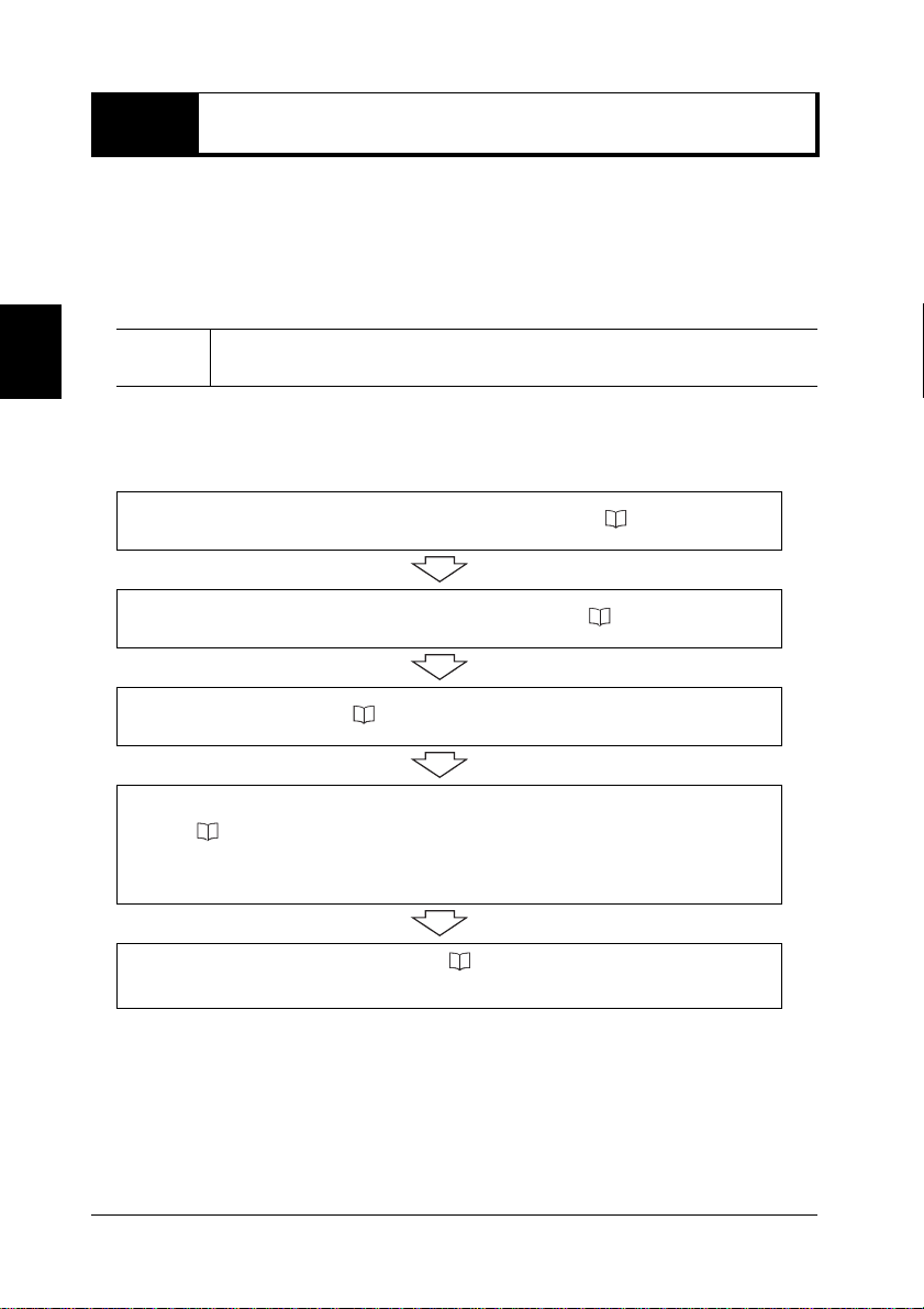
z Initial setup
Note
1
2
3
4
5
After connecting the communication unit to t he computer, be sure to charge
the BL-N90 before use.
Connect the power cable to the communication unit. ( page 2-3).
Connect the communication unit to your computer ( page 2-5).
Charge the BL-N90 ( page 2-11).
Establish a connection between the BL-N90 and the communication unit
( page 2-13).
Use the BL-N90 to read the BD address barcode attached to the
communication unit.
Initialize settings for the BL-N90 ( page 2-15).
Read the initialization barcode using the BL-N90.
2-2
Page 23

2-2
Procedure
Connect the power cable to the communication unit before use.
Connecting the Power Cable to the Communication Unit
z Included parts
• AC power cable for the BL-N90
(The supplied AC cable can only be used in Japan. To use the BL-N90 Series in another
country, use the AC cable applicable to that country ( page 1-2).)
• Communication unit
• AC adaptor for the communication unit
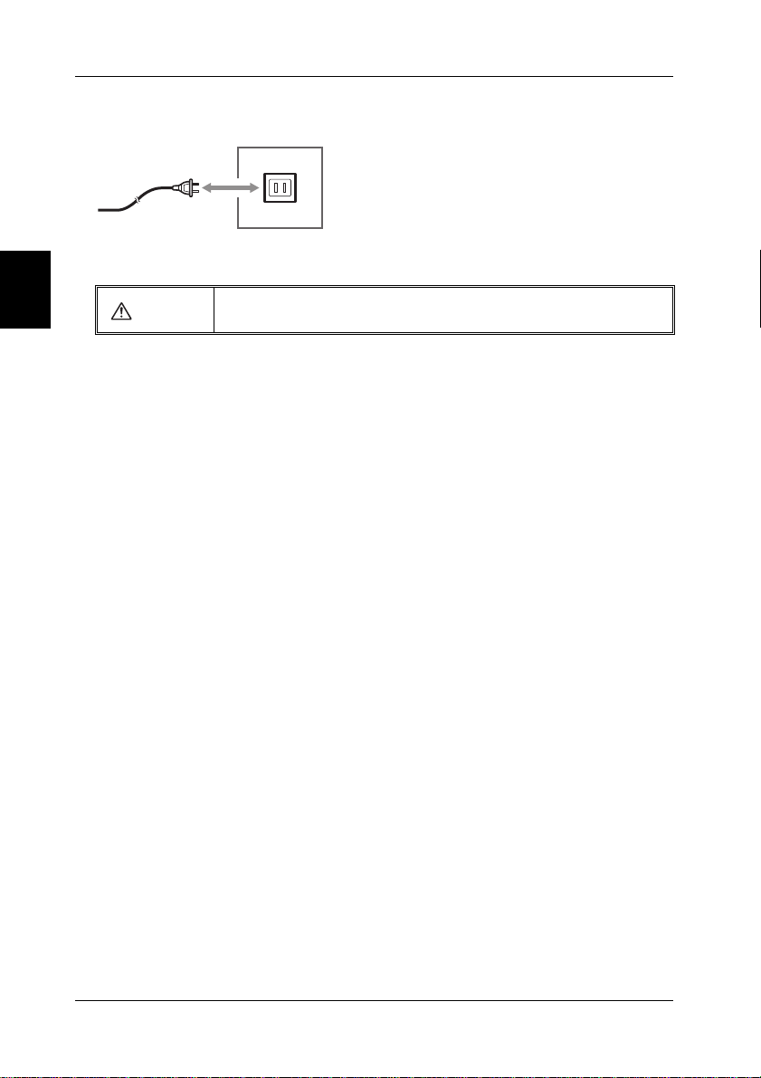
1 Connect the AC cable to the AC adaptor.
2
Initial Setup
2-3
Page 24

2-2 Connecting the Power Cable to the Communication Unit
2 Connect the AC connector on the back of the communication unit to the AC adaptor.
After connecting the AC adaptor, pass the cable behind the hook.
BL-N9UB BL-N9V/N9R
2
Initial Setup
2-4
1
2
1
2
Page 25

2-3 Connecting the Communication Unit
Procedure
BL-N9UB
To computer
USB port
(A type)
After connecting the power cable to the communication unit, connect the communication unit
to the computer using the interface provided.
Connecting the BL-N9UB to the Computer
Use the USB cable to connect the communication unit to the computer.
The barcode reader is compatible with Windows7/Vista/XP/2000/98.
1 Turn on the computer.
2 Connect the communication unit's interface cable to the USB port on the computer.
The blue LED on the communication unit will flash.
After connecting the device to your computer for the first time, install the USB driver ( page 2-6).
2
Initial Setup
3 Connect the power cable to an AC outlet, and turn on the communication unit.
Be sure to use the AC adapter provided with the de vice. Using anot her pow er
CAUTION
•
source may cause fire, electrical shock, or damage to the equipment.
2-5
Page 26

2-3 Connecting the Communication Unit
Procedure
Installing the USB driver
When BL-N9UB is first connected to a computer running Windows 98, the USB driver
installation screen appears. Install the driver by following the directions given on the screen.
Note
Connect the barcode reader after turning on the computer. If the barcode reader is
connected with the power off, turn the computer on.
2
Initial Setup
1 The "Add New Hardware Wizard" dialog appears and the message "This window searches
for new drivers for: USB human interface device" is displayed. Click on the [Next] button.
2 The message "What do you want Windows to do?" is displa yed. Select [Search f or the best
driver for your device (Recommended).] and click on the [Next] button.
3 Click on the [Next] button. "USB human interface device" is displayed and the message
"Windows driver search for the device: " appears. Click on the [Next] button.
Note
4 Windows begins installing the driver. When installation is complete, the message
"Windows has finished installing the software that your new hardware device requires. "
appears. Click on the [Finish] button.
The CD-ROM (Windows) may be required depending on the computer environment.
2-6
Page 27

2-3 Connecting the Communication Unit
Procedure
BL-N9V
To keyboard
PS/2 connector
(Mini DIN 6-pin)
To computer
PS/2 connector
Connecting the BL-N9V to the Computer
Use the keyboard interface to connect the communication unit to your computer. Compatible
computers include PC/AT (DOS/V) machines.
1 Turn off the computer.
CAUTION
Do not remove the cables while the computer is turned on.
This could cause damage to the computer and the barcode reader.
2 Connect the communication unit's interface cable to your computer's keyboard connector,
as indicated in the diagram.
2
Initial Setup
Note
When connecting a keyboard connector plug to an AT connector, use a commercial
keyboard conversion adapter for the connection.
2-7
Page 28
2-3 Connecting the Communication Unit
3 Connect the power cable to an AC outlet, and turn on the communication unit.
The blue LED on the communication unit will flash.
2
Initial Setup
4 Turn on your computer.
CAUTION
Be sure to use the AC adapter provided with the device. Using another power
source may cause fire, electrical shock, or damage to the equipment.
2-8
Page 29

2-3 Connecting the Communication Unit
Procedure
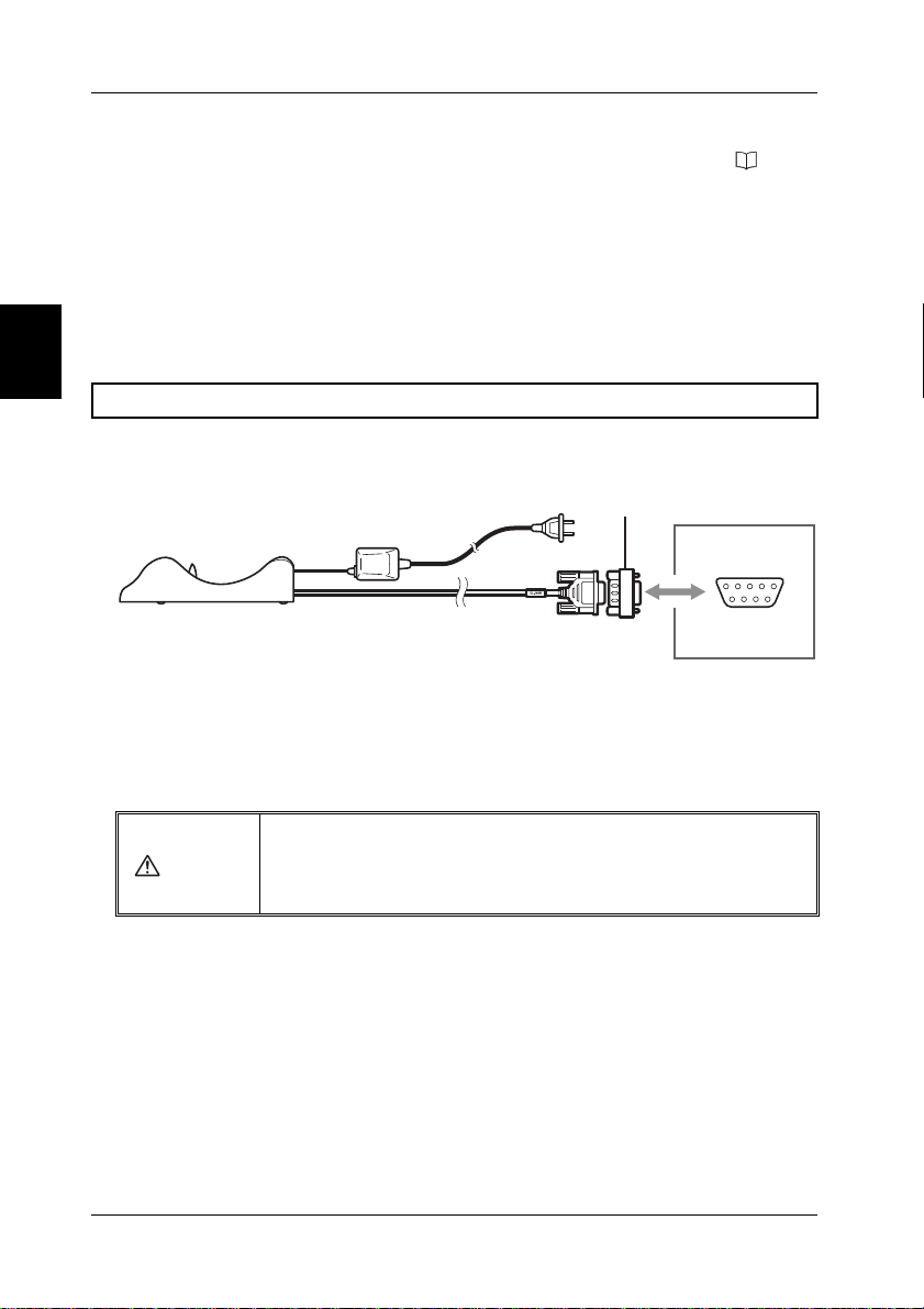
BL-N9R
RS-232C
To computer
(D-sub 9-pin)
Pin No. Symbol Description Signal direction
2 SD (TXD) Sends data Output
3 RD (RXD) Receives data Input
4–
Do not make any connection
–
5 SG Signal ground –
6–
Do not make any connection
–
7 CS (CTS) Send OK Input
8 RS (RTS) Send request Output
D-sub 9-pin (female)
#4-40 screws
Connecting the BL-N9R to the Computer
A communication unit with an RS-232C interface may be used in conjunction with an RS232C enabled device. This section explains procedures for connecting the barcode reader
to a computer, as well as connecting the barcode reader to an Auto IDdata controller DV-90
(
page 2-10).
1 Turn on your computer.
2 Connect the communication unit's interface cable to the RS-232C port on your computer.
3 Connect the power cable to an AC outlet, and turn on the communication unit.
The blue LED on the communication unit will flash.
•
CAUTION
z RS-232C pin configuration of the BL-N9R
Be sure to use the AC adapter provided with the de vice. Using anot her pow er
source may cause fire, electrical shock, or damage to the equipment.
2
Initial Setup
2-9
Page 30
2-3 Connecting the Communication Unit
z Communication settings
Factory settings for the BL-N90 are given below. The settings can be changed ( page
4-23). Make sure that the settings for BL-N90 and the connected computer are the same.
• Baud rate : 9600 bit/s
• Data length : 7 bits
• Parity : Even
• Stop bit : 1 bit
• Communication protocol: No protocol
2
Connecting the DV-90
Initial Setup
To connect the device to a DV-90, an adaptor like the one shown in the diagram below is
required.
Conversion connector
BL-N9R
The following adaptor is recommended.
• Manufacturer : Elecom
• Product name : Serial Reverse Adaptor
• Model : AD-R9
DV-90
RS-232C
(D-sub 9-pin)
2-10
CAUTION
• Be sure to use the AC adapter provided with the de vi ce . Using another po wer
source may cause fire, electrical shock, or damage to the equipment.
• Power is supplied by the AC adaptor. The D-sub connector does not supply
power.
Page 31

2-4 Charging the BL-N90
Procedure
To computer
The communication unit is used to charge the BL-N90.
The barcode reader is shipped with zero charge. Ple ase charge the device before use.
Note
The barcode reader may be used to scan ( page 2-13) after a charge of just 20
minutes.
z Charging
1 Connect the communication unit to the computer using the appropriate connection method
and make sure both sides are powered on.
For details on connection methods, see "Connecting the Communication Unit" on page 2-5.
2 Set the scanner into the communication unit securely , to ensure that the charging terminals
stay in place.
As the unit begins to charge, the yellow LED on the scanner begins to flash .
Charging is complete once the yellow light stops flashing .
A full charge takes approximately 4 hours.
Please periodically clean the charging terminals on the scanner and the
•
communication unit ( "Maintenance" on page 8).
Dirt in the terminals may interfere with charging.
Note
If too much dirt covers the charging terminals, an alarm may sound.
• The scanner can be configured to sound an alarm when it is unable to charge
properly, such as when the charging terminals are misaligned ( "Charge Error
Prevention" on page 3-13).
• The BL-N90 Series cannot be charged in sleep mode ( page 3-14).
2
Initial Setup
2-11
Page 32

2-4 Charging the BL-N90
Rechargeable Batteries for the BL-N90
The BL-N90 sounds an alarm when the battery is low.
When using the scanner, be mindful of the alarm and always maintain a charge.
z Battery low alarm
When the BL-N90 battery level gets low, the following alarms are sounded.
• Each time a barcode is read, the buzzer sounds twice
•
2
Initial Setup
Note
If the laser only lights for a short period of time after pressing "Trigger", then there is
low battery power.
• If the laser does not light after pressing "Trigger", then the battery is completely
depleted.
z Continuous use capacity
The following table offers estimates of how long the BL-N90 can be used continuously on
a full charge.
Condition for use Estimated continuous use time
One scan every 10 seconds Approx. 10 hours
One scan every 5 seconds Approx. 8.5 hours
Idle with full charge
Sleep mode with full charge
* Since the BL-N90 and the communication unit are continuously communicating wirelessly,
battery power is depleted even when the scanner is not in use.
• When not in use, it is recommended that you set the scanner in the communication unit.
• When not using the device for long periods, enabling sleep mode ( page 3-14) interrupts
the wireless communication, thereby saving battery power.
*
*
.
Approx. 12 hours
Approx. 54 hours
2
The continuous use times listed above are estimates. Actual times may vary.
Note
•
• If the continuous use times decrease significantly, then it is time to replace the
batteries. Contact your nearest KEYENCE office.
z Charging time
A fully depleted (no charge) battery takes approximately 4 hours to fully charge.
2-12
Page 33

2-5 Establishing a Connection
Procedure
The BL-N90 and the communication unit communicate as a pair. This section describes how to
establish a connection between the BL-N90 and the communication unit.
Note
Note
Perform the following operation with the communication unit connected to your
computer ( page 2-5).
The following symptoms indicate that a connection is not established.
• The blue LED on the scanner is flashing
• The blue LED on the communication unit is flashing
At this stage, perform the following steps.
Note that even when using multiple BL-N90 scanners, each scanner can only
communicate with its pair communication unit ( page 2-14).
1 Press "Trigger" to activate the laser.
2 Scan the barcode attached to the communication unit.
2
Initial Setup
After 10 to 30 seconds, a connection will be established.
Once a connection is established, the devices will be in the following state:
• The blue LED on the scanner is lit.
• The blue LED on the communication unit is lit.
2-13
Page 34

2-5 Establishing a Connection
Procedure
Notes for Establishing a Connection
z Scanning a barcode
The scanner cannot read a barcode unless a connection has been established with the
communication unit. (Buzzer will sound.)
z Using multiple BL-N90 scanners
2
Initial Setup
• Only the connected scanner and communication unit pair can communicate with one
another.
• If multiple BL-N90 scanners read the same communication unit barcode, only the first
scanner to read the communication unit can communicate with it.
To change the pairing, follow the procedure below entitled "Swapping out the BL-N90".
z Swapping out the BL-N90
When swapping one BL-N90 scanner for another, follow the procedure below.
1
Hold down "Trigger" on the paired BL-N90 for about 10 seconds to enable sleep mode.
A beep will sound as sleep mode is enabled ( page 1-6).
During sleep mode, the wireless connection is disabled, causing the blue LED on the
communication unit to flash. This connection must be disabled in order for the communication
unit to pair with another BL-N90.
2 Use the second BL-N90 to scan the barcode of the communication unit.
3 Scan the initialization barcode ( page 2-15).
If multiple BL-N90 units read the BD address barcode for the same communication
Note
2-14
unit, you will not be able to determine which BL-N90 the communication unit will
establish a connection with.
Always combine the BL-N90 and the communication unit in a single pair.
Page 35

2-6
Procedure
After establishing a connection between the BL-N90 and the communication unit, be sure to
initialize its configuration. This ensures that the scanner's configuration is initialized to match
the interface type of the communication unit.
Perform this operation in the following situations:
• Before using the BL-N90 for the first time
• After connecting the BL-N90 to a communication unit with a different communication
interface
Initializing the BL-N90
1 Press "Trigger" to activate the laser.
2 With the laser light about 100 mm from the page, scan the "Initialization" barcode below.
Once scanning of the "Initialization" barcode is complete, a beep will sound 3 times.
<Initialization>
2
Initial Setup
Note
Scanning the initialization barcode initializes all of the settings.
2-15
Page 36

2-7 Reading a Barcode
This section describes the basic barcode scanning operations.
Scanning a Barcode
The scanner is able to read barcodes when it is connected wirelessly to the communication unit.
The wireless connection can be verified by checking that the blue LED on the communication
unit is lit ( page 1-6).
2
1 Press "Trigger" to activate the laser.
Initial Setup
As the laser is activated, the blue LED on the BL-N90 lights up .
2 Aim the laser to cover the entire barcode.
Readable range
Laser
Read distance: 100 mm
Operation check LED
Trigger switch
3 Once scanning is complete, the white LED lights up, a beep will sound once ,
and data is transmitted to your computer.
2-16
1
Page 37

2-7 Reading a Barcode
To p
Bottom
z Precautions for reading
• If the scanner cannot communicate with the communication unit wirelessly, then the
barcode will not be read. (A low-pitched beep will sound twice.)
• Be sure to aim the laser to scan the entire length of the barcode.
{ Correct Scan XIncorrect Scan
2
• Only shine the laser light on one barcode at a time. Scanning multiple barcodes at once
can lead to scan errors, or barcodes being scanned out of order.
X Incorrect Scan
• Depending on the laser reflection, interior lighting, or barcode label angle, light reflected
from the label may be partially reflected, resulting in scan errors.
In such situations, adjust the label and laser angle or distance.
• When scanning an RSS Stacked barcode, aim the laser and scan from the top of the
barcode to the bottom, or from the bottom to the top.
z Caution when using the BL-N9UB/N9V
When using the BL-N9UB/N9V, barcode data read by the BL-N90 is treated as data
entered through the keyboard. In this way, data may be input directly into the running
application, without the need for special drivers.
When using the BL-N9UB/N9V, please note the following:
• Do not try to read a barcode while pressing down a key on the computer's keyboard. Do
not press a key while receiving the data. Data input will not be read correctly.
• If the computer has multiple language settings, make sure that the input mode is set for
half-width alphanumeric characters.
Initial Setup
2-17
Page 38

2-8 Checking the Connected Pair
t
In locations where there are multiple BL-N90, the connected pairs must be verified. For
example, this function can be used when you are unsure which BL-N90 is connected to
which communication unit.
z Checking the connected pair
After establishing a connection between the BL-N90 and the communication unit, press
2
Initial Setup
the page button on the communication unit.
Page button
The BL-N90 acts as follows.
• All of the LED flash simultaneously
• The buzzer sounds continuously
.
Repea
.
Note
z Ending verification
Press the page button on the communication unit again to stop the buzzer and LED
flashing on the BL-N90.
2-18
After establishing a connection between the BL-N90 and the communication unit, the
blue LED lights up.
Page 39

2-9 Wireless Connection Environment
The BL-N90 and the communication unit use Bluetooth Version 1.2 for their wireless
communication.
Please use in the following environment.
z Communication range and surrounding conditions
The BL-N90 and the communication unit have a line-of-sight range of approximately 10
meters.
However, obstacles placed between the scanner and the communication unit, such as
concrete or metal, may interrupt the wireless connection. Please use the device in an
environment free of these obstacles.
2
Initial Setup
Good
Bad
Obstacle
Also read the notes regarding wireless communication ( Page 4).
z When the wireless connection is interrupted
The following occur when the wireless connection is interrupted:
•The blue LED on the BL-N90 flashes
•The blue LED on the communication unit flashes
Once a connection can be established again, the scanner and communication unit
automatically reconnect.
• Reconnection may take between 10 to 30 seconds.
• During this time, barcodes cannot be read. (Buzzer will sound.)
2-19
Page 40

2-9 Wireless Connection Environment
2
Initial Setup
MEMO
2-20
Page 41

3
Descriptions of Key
Functions
This chapter describes reading data, the format for sending read
data, and the connection interfaces.
3-1 Reading . . . . . . . . . . . . . . . . . . . . . . . . . . . . . . .3-2
3-2 Selecting the Reading Mode . . . . . . . . . . . . . .3-5
3-3 Sending the Reading Data . . . . . . . . . . . . . . . .3-9
Settings for Each Communication Interface. . .
3-4
3-5 Charge Error Prevention. . . . . . . . . . . . . . . . .3-13
3-6 Sleep Mode . . . . . . . . . . . . . . . . . . . . . . . . . . .3-14
3-11
3
Descriptions of Key Functions
3-1
Page 42

3-1 Reading
z Selecting the reading mode
There are three types of barcode reading modes.
The setting can be changed according to the application.
• Trigger switch mode
• Auto-scan/trigger switch reading mode
• Auto-scan/auto-reading mode
For more details about the operation of each mode, see page 3-5.
z Read data
3
Descriptions of Key Functions
Read data is sent to the connected computer.
• For the format of the sent data, see page 3-9.
• For information about the communication protocols when using BL-N9R with the
communication unit, see page 3-11.
3-2
Page 43

3-1 Reading
Functions when Reading the Barcode
z Rereading prevention
The "rereading prevention function" ensures that an emitted laser does not accidentally
read the same barcode twice in a row.
If a single barcode is read multiple times within the specified rereading prevention time,
then the subsequent readings are ignored.
• Factory setting: 375 ms
Time can be set to 250 ms or greater in 125 ms units ( page 4-17).
• After a barcode had been read correctly, to read the same barcode again, either turn off
the laser light temporarily or move the barcode away from the reading window for about
one second to clear the reread prevention time.
z Limit read digits
This function limits the number of digits read when reading a barcode. Digits in the
barcode that exceed the limit are invalidated.
There are two types of settings ( page 4-18).
• Limit all : All types of registered codes are limited.
• Limit individual : An individual type of code is limited.
z Buzzer tone selection
The buzzer that signals various operations can be muted or set to seven different tones
( page 4-15).
3
Descriptions of Key Functions
Note
The buzzer used while configuring the settings cannot be changed.
3-3
Page 44

3-1 Reading
1
2
Repeat
z Number of beeps from the buzzer
The buzzer sounds according to the operations shown in the following table.
3
Descriptions of Key Functions
Number of
beeps
1 time
2 times During reading: low remaining battery
3 times
Continuous
Error: 1 time
Error: 1 to 2
times
When barcode reading is complete
During sleep mode (long buzzer)
When wireless communication is disconnected
When wireless communication is reconnected
When reading the program barcode
3
Press the page button on the communication unit to check the connection, then
press the page button again to stop the buzzer.
When a normal barcode is read while setting the program
When a barcode is read without establishing wireless communication
BL-N90 status
3-4
Page 45

3-2 Selecting the Reading Mode
There are three types of operation modes when reading barcodes.
You can change the reading mode depending on the application ( page 4-13).
Selecting the Reading Mode
z Trigger switch mode (Basic mode)
This mode is the initial setting (factory default).
Press "Trigger" to read a barcode.
Press and hold "Trigger" to continuously read barcodes.
3
Descriptions of Key Functions
• The laser will continue to emit for a set period of time (default: 0.5 s) after "Trigger" is
released.
This set time can be changed ( page 4-13).
• Press "Trigger" while the laser is emitted to read a barcode.
• After pressing "Trigger", if a barcode is not read for 5 or more seconds, the laser stops
emitting.
3-5
Page 46

3-2 Selecting the Reading Mode
Detection
sensor
z Auto scan mode (two types)
BL-N90 has a sensor built into the transmitter/receiver.
Auto scan mode is a mode that automatically starts
emitting
a laser after the sensor detects an object such as white
paper.
There are two types of modes:
"Auto-scan/trigger switch reading mode" and
"Auto-scan/auto-reading mode".
Select the sensor detection distance from the following options ( page 4-14).
• Mid-distance: 0 to 100 mm (±25 mm)
• Long distance: 0 to 230 mm (±50 mm)
The initial setting (factory default) is "Long distance".
3
Descriptions of Key Functions
Auto-scan/trigger switch reading mode (target reading)
This mode is useful in situations such as reading barcodes that are aligned in a column
with only a narrow space between them.
Bringing the BL-N90 close to the barcode sheet starts the laser emission. Align the laser
with the barcode you want to read and press "Trigger" to perform the scan.
Press "Trigger" while the laser is emitted to read several barcodes in a row.
If a barcode is not read, or if the barcode sheet is moved far away, the laser tur ns off
after 3 to 10 seconds.
Note
3-6
If the laser turns off while reading a barcode, move the barcode sheet out of the sensor
detection range once, then bring the sheet close again to start emitting the laser.
Page 47

3-2 Selecting the Reading Mode
Auto-scan/auto-reading mode (proximity reading)
This mode is useful when the BL-N90 is secured to the optional dedicated stand and the
barcode sheet is brought close for reading.
For information about using the dedicated stand, see page A-9.
Bring the barcode sheet close to the BL-N90 to start the laser emission.
When the laser is positioned on a barcode, it is automatically read.
When the laser is on, barcodes can be read continuously.
If a barcode is not read, or if the barcode sheet is moved far away, the laser turns off
after 3 to 10 seconds.
3
Descriptions of Key Functions
Note
•
If the laser turns off during automatic reading, move the barcode sheet out of the
sensor detection range once, then bring the sheet close again to start emitting the
laser.
• The BL-N90 cannot be charged while in the dedicated stand.
When using the dedicated stand, keep an e y e on the b attery lev el and alw a ys charge
the BL-N90 in the communication unit after operations are complete.
3-7
Page 48

3-2 Selecting the Reading Mode
z Reading on the communication unit
When an "Auto-scan" mode (auto-reading/trigger switch reading) is set on the BL-N90, the
scanner operates in "Auto-scan/auto-reading mode" when it is set on the communication
unit.
• The sensor detection distance can be selected ( page 4-14).
When performing reading with the BL-N90 set on the communication unit, it is
Note
constantly being charged. You do not have to worry about the battery running out.
When using the dedicated stand, the BL-N90 cannot be recharged and the ba ttery may
run out.
3
Descriptions of Key Functions
3-8
Page 49

3-3 Sending the Reading Data
Header
Symbol identifier
Read data
Terminator
12 43
Read barcode data is sent to the computer connected to the communication unit with the
following information added to the data: header, symbol identifier, and terminator.
If the barcode cannot be read correctly, the data is not sent.
Data Format
* Special characters are not needed to divide the data into segments 1 to 4.
Factory default values
• Header : None
• Symbol identifier : Not added
• Terminator : [CR]
These settings can be changed ( page 4-21).
z Details of the format data
1 Header
A character can be added to indicate the start of data.
• This parameter can be set to None, [STX], or [TAB] (HT).
2 Symbol identifier
A symbol identifier can be added to the barcode.
Code type Data specifications
No check digit ]A0
CODE39
ITF
Codabar (NW-7) – ]F1
Inspect check digit (Sent) ]A1
Inspect check digit (Not sent) ]A3
No check digit ]I0
Inspect check digit (Sent) ]I1
Inspect check digit (Not sent) ]I2
Symbol
identifier
3
Descriptions of Key Functions
3-9
Page 50

3-3 Sending the Reading Data
Code type Data specifications
EAN/UPC 13 digits ]E0
EAN/UPC 8 digits ]E4
EAN/UPC
CODE128
CODE93 – ]G0
RSS – ]e0
UPC-A 13 digit format
UPC-A 12 digit format
UPC-E ]X0
Not GS1-128 ]C0
Is GS1-128 ]C1
Second digit of data is FNC1 ]C2
Symbol
identifier
]E0
3
3 Read data
Descriptions of Key Functions
These digits contain the read barcode data.
4 Terminator
A character can be added to indicate the end of data.
• This parameter can be set to [CR], [CR][LF], [TAB], or [ETX].
Inter-character Delay
The time between each character can be set to three levels for the data sent from the BL-N90
series to the computer ( page 4-22).
If the processing speed on the computer is slow, set a longer value for the inter-character
delay. If the delay is not set long enough, the computer processing speed may fall behind
and digits may be dropped from the data. Adjust the inter-character delay so that data is
received correctly from the reader.
3-10
Page 51

3-4
Settings for Each Communication Interface
Keyboard/USB Connection Interface (BL-N9V/N9UB)
The keyboard specifications can be selected ( page 4-23).
z Localized settings
BL-N9V/N9UB are compatible with the following keyboard languages.
• JAPANESE . . . . . . . . . . . . . . . . . .Japanese specifications
• USA . . . . . . . . . . . . . . . . . . . . . . . .American specifications
RS-232C Communication Interface (BL-N9R)
The RS-232C communication protocol can be set to no protocol, RTS/CTS, or ACK/NAK
( page 4-24).
z No protocol
There is no procedure used for communication Once the barcode is read, the data is sent
in sequence.
z RTS/CTS
The CTS signal for RS-232C (RTS on the host side) can wait to send data by using the
following methods.
• CTS signal off (Low) : Waits to send data.
• CTS signal on (High) : Sends data.
Barcodes cannot be read while waiting to send data.
RTS signal for RS-232C
Note
• With "No protocol," the RTS signal is normally set to "Always on (High)".
• With "RTS/CTS," the RTS signal becomes "On only when sending data (High)."
3
Descriptions of Key Functions
3-11
Page 52

3-4 Settings for Each Communication Interface
z ACK/NAK
The reader sends data between the host by using the following procedure.
1 Read data is sent to the host from BL-N9R.
BL-N9R waits for a response from the host (ACK [06h]: Completed without errors, NAK
[15h]: Request resend). While waiting for ACK [06h], the next barcode cannot be read.
2 The response is sent from the host to BL-N9R.
When the ACK [06h] response is sent, the first communication is completed.
•
BL-N9R can send the following read data (it does not respond with ACK [06h]).
•
When the NAK [15h] response is sent, BL-N9R resends the same data and waits for the
ACK [06h] response.
3
Descriptions of Key Functions
3-12
Page 53

3-5 Charge Error Prevention
Charging terminals
To computer
BL-N90 includes a feature to warn users about charge errors.
z Charge error prevention
This function sounds an alarm if the BL-N90 is set in the communication unit and fails to
charge correctly.
The function is turned off in the initial setting (factory default).
The following situations may cause the scanner to charge incorrectly.
• The charging terminals for the BL-N90 and the communication unit are not touching.
→ Reset the BL-N90 so that the charging terminals touch correctly.
• The charging terminals are dirty.
→ For details about cleaning the charging terminals, see "Maintenance" on page 8.
3
Descriptions of Key Functions
z Using charge error prevention
To use this detection function, switch the "Charge error prevention function" setting on the
BL-N90 to "On."
For information about setting this function, see page 4-25.
3-13
Page 54

3-6 Sleep Mode
Set the BL-N90 to sleep mode in the following situations.
• When not using the BL-N90 for a long period of time
Since the BL-N90 and the communication unit are continuously communicating wirelessly,
battery power is depleted even when the scanner is not reading a barcode. Enabling
sleep mode interrupts the wireless communication to the communication unit, thereby
saving battery power.
For details on power consumption, see page 2-12.
• When changing the BL-N90 pairing (when using multiple BL-N90 and communication
units)
When changing the BL-N90 pairing, set the BL-N90 that is currently being used to sleep
mode.
3
Descriptions of Key Functions
For details about changing the pairing, see page 2-14.
z Setting sleep mode
Press and hold "Trigger" for about 10 seconds.
After setting sleep mode, the following actions occur.
• The buzzer sounds once long beep.
• The blue LED on the communication unit lights up (wireless communication stopped).
z Releasing sleep mode
To release the sleep mode, press "Trigger".
• Wait 10 to 30 seconds until wireless communication starts.
• Once wireless communication starts, the blue LED on the communication unit lights up.
1
3-14
Page 55

4
Program
This chapter describes how to change reading procedures or set
functions for the BL-N90 Series.
4-1 Using the Program Barcode Menu. . . . . . . . . .4-2
4-2 Starting and Ending the Program . . . . . . . . . .4-3
4-3 Settings for the Barcode Type . . . . . . . . . . . . .4-4
4-4 Setting the Reading Mode . . . . . . . . . . . . . . .4-13
4-5 Buzzer Settings . . . . . . . . . . . . . . . . . . . . . . . .4-15
4-6 Decode Settings . . . . . . . . . . . . . . . . . . . . . . .4-16
4-7 Settings for Limit Read Digits . . . . . . . . . . . .4-18
4-8 Communication Data Format Settings . . . . . 4-21
4-9 Settings for Each Connection Interface . . . . 4-23
4-10 Other Settings . . . . . . . . . . . . . . . . . . . . . . . . .4-25
4-11 Decimal Program Code . . . . . . . . . . . . . . . . . . 4-26
4-12 Code Type List. . . . . . . . . . . . . . . . . . . . . . . . .4-27
4
Program
4-1
Page 56

4-1 Using the Program Barcode Menu
3
Read the program barcode menu to make changes to the program for the BL-N90 Series.
Configuring the Program
Use steps 1 to 3 as shown below to change the program.
Steps 1 and 3 (reading the Start/End Program barcode) can be omitted when configuring
settings other than the ones listed below.
• Laser off time setting ( page 4-13)
• Limit read digits ( page 4-18)
4
Note
Program
1
2
3
Note
Before configuring the program, complete steps 1 to 5 of "Initial Setup" ( page 2-2)
and check that wireless communication is established between the BL-N90 and the
communication unit (the blue LED is lit on the comm unication unit).
Read the "Start/End Program" barcode.
Read all of the program barcodes for setting that you want to change.
To save the settings, read the "Start/End Program" barcode.
During program mode, an error alarm sounds when a barcode other a program
•
barcode is read. Do not read a barcode other than a program barcode during
program mode.
• If a program barcode is not read for about one minute during program mode, a
buzzer sounds three times
ends. Restart the settings from the beginning to make changes.
, the set information is lost, and program mode
3
3
4-2
Page 57

4-2 Starting and Ending the Program
Start/End Program
To start or end the program, read the barcode for "Start/End Program."
Initialization
Read this barcode to return all of the settings to the factory defaults.
4
Program
4-3
Page 58

4-3 Settings for the Barcode Type
These barcodes set the types of barcodes that can be read.
The settings surrounded by the < > marks are the factory default settings.
Code Type Settings
EAN/UPC
<
ON> OFF
CODE128
4
Program
CODE39
ITF
Industrial 2of5
<
ON> OFF
<
ON> OFF
<
ON> OFF
<
ON> OFF
4-4
Page 59

4-3 Settings for the Barcode Type
Codabar (NW-7)
ON> OFF
<
CODE93
ON> OFF
<
Settings for reading GS1DataBar
When making settings to read GS1DataBar, make the appropriate settings for all of the
following four types of code.
Supported GS1DataBar
ON <OFF>
4
Program
GS1DataBar Omnidirectional
ON <OFF>
GS1DataBar Limited
ON <OFF>
GS1DataBar Expanded
ON <OFF>
4-5
Page 60

4-3 Settings for the Barcode Type
EAN/UPC Detailed Settings
UPC-A
<
ON> OFF
Extend UPC-A to EAN-13 digit
<
ON> OFF
4
Send UPC-A check digit
Program
<
ON> OFF
UPC-E
<
ON> OFF
Send UPC-E check digit
ON <OFF>
Add the UPC-E system code "0"
ON <OFF>
4-6
Page 61

EAN13
<
ON> OFF
Send EAN13 check digit
<
ON> OFF
EAN8
<
ON> OFF
Send EAN8 check digit
4-3 Settings for the Barcode Type
4
Program
<
ON> OFF
Read EAN add-on 2 digits
ON <OFF>
Read EAN add-on 5 digits
ON <OFF>
4-7
Page 62

4-3 Settings for the Barcode Type
Read only EAN add-on code
Normal EAN code cannot be read if this setting is turned on.
ON
CODE128 Detailed Settings
GS1-128
<
ON> OFF
4
Program
Send ]c1 symbol identifier
<
ON> OFF
Group separator settings
* When using BL-N9V/N9UB, set this parameter to [SPC] (space).
<[GS]> [SPC]
<OFF>
4-8
Page 63

CODE39 Detailed Settings
Send start character and stop character
ON <OFF>
Check digit inspection
* "Module 43" is used as the method to calculate the CODE39 check digit.
4-3 Settings for the Barcode Type
ON
Send check digit
<
ON> OFF
<OFF>
4
Program
4-9
Page 64

4-3 Settings for the Barcode Type
Codabar (NW-7) Detailed Settings
Send start character and stop character
<
ON> OFF
Uppercase or lowercase start character and stop character
<
Upper case> Lower case
4
Check digit inspection
* "Module 16" is used as the method to calculate the Codabar (NW-7) check digit.
Program
ON
Send check digit
<
ON> OFF
<OFF>
4-10
Page 65

ITF Detailed Settings
Check digit inspection
* "Module 10/3" is used as the method to calculate the ITF check digit.
4-3 Settings for the Barcode Type
ON
Send check digit
<
ON> OFF
<OFF>
GS1DataBar Omnidirectional Detailed Settings
Send check digit
<
ON> OFF
Send application identifier
<
ON> OFF
4
Program
Send symbol identifier
<
ON> OFF
4-11
Page 66

4-3 Settings for the Barcode Type
GS1DataBar Limited Detailed Settings
Send check digit
<
ON> OFF
Send application identifier
<
ON> OFF
4
Program
Send symbol identifier
<
ON> OFF
GS1DataBar Expanded Detailed Settings
Send symbol identifier
<
ON> OFF
4-12
Page 67

4-4 Setting the Reading Mode
Read the decimal program codes
( page 4-26) three times
Reading Mode
z Trigger switch mode
Setting the laser off time
After reading the "Trigger switch mode" barcode above, use the following method to
set the laser off time setting.
• To set the time, read three barcodes for the decimal program code ( page 4-26).
The time can be set between 500 and 15,000 ms in 100 ms intervals.
Example: To set the trigger off time to 3 seconds (3000 ms):
1. Read the "Laser off time setting" barcode.
2. Read the decimal program code "0." The buzzer sounds once.
3. Read the decimal program code "3." The buzzer sounds two times.
4. Read the decimal program code "0." The buzzer sounds three times.
Laser off time setting
z Auto-scan/trigger switch reading mode
z Auto-scan/auto-reading mode
4
Program
4-13
Page 68

4-4 Setting the Reading Mode
z Auto-scan detection distance
<Long distance> Mid-distance
Reading on the Communication Unit
z Auto-scan detection distance
<Long distance> Mid-distance
4
Program
4-14
Page 69

4-5 Buzzer Settings
Tone Selection
Tone 0 <Tone 1>
Tone 2 Tone 3
Tone 4 Tone 5
4
Program
Tone 6 No buzzer
4-15
Page 70

4-6 Decode Settings
Settings for the Number of Times to Read Matching Barcodes
1st match <2nd match>
3rd match 4th match
4
Program
5th match 6th match
4-16
7th match 8th match
Page 71

Selecting the Reread Prevention Time
None 250 ms
<375 ms> 500 ms
4-6 Decode Settings
625 ms 750 ms
875 ms 1000 ms
Infinite
4
Program
4-17
Page 72

4-7 Settings for Limit Read Digits
The limit read digits function can be set to one of the following options.
Select the appropriate setting for the intended application.
z Limit all settings
This option reads the set number of digits for the barcode, no matter what type of code is
being read.
To set the number of digits, read three barcodes for the decimal program code ( page
4-26).
z Limit individual settings
This option sets the number of digits and code type to read for the block and reads only
the specified block.
• Up to seven blocks can be specified.
• When limiting multiple digits for the same type of code, set the limits by block.
4
Program
• When setting multiple blocks, the blocks must be set towards the beginning of the list
from block 1.
• Set the number of digits to read by using the decimal program code ( page 4-26).
• Set code type ( page 4-27) by using the decimal program code ( page 4-26).
Example 1: Read 10 digits for CODE39 and 14 digits for ITF
Block 1 settings
1. Read the "Block 1 — digit settings" barcode.
2. Read the decimal program codes "0," "1," and "0."
3. Read the "Block 1 — code type settings" barcode.
4. Read the decimal program codes "0," "8," and "0."
Block 2 settings
5. Read the "Block 2 — digit settings" barcode.
6. Read the decimal program codes "0," "1," and "4."
7. Read the "Block 2 — code type settings" barcode.
8. Read the decimal program codes "0," "8," and "2."
4-18
Page 73

Example 2: Read only 8 to 10 digits for Codabar (NW-7).
Read the decimal program codes
( page 4-26) three times
Block 1 settings
1. Read the "Block 1 — digit settings" barcode.
2. Read the decimal program codes "0," "0," and "8."
3. Read the "Block 1 — code type settings" barcode.
4. Read the decimal program codes "0," "8," and "1."
Block 2 settings
5. Read the "Block 2 — digit settings" barcode.
6. Read the decimal program codes "0," "0," and "9."
7. Read the "Block 2 — code type settings" barcode.
8. Read the decimal program codes "0," "8," and "1."
Block 3 settings
9. Read the "Block 2 — digit settings" barcode.
10. Read the decimal program codes "0," "1," and "0."
11. Read the "Block 2 — code type settings" barcode.
12. Read the decimal program codes "0," "8," and "1."
z Limit all settings
4-7 Settings for Limit Read Digits
4
Program
Start limit all settings
z Limit individual settings
Block 1 settings
Block 1 — digit settings Block 1 — code type settings
Block 2 settings
Block 2 — digit settings Block 2 — code type settings
4-19
Page 74

4-7 Settings for Limit Read Digits
Block 3 settings
Block 4 settings
Block 5 settings
4
Program
Block 6 settings
Block 3 — digit settings Block 3 — code type settings
Block 4 — digit settings Block 4 — code type settings
Block 5 — digit settings Block 5 — code type settings
Block 6 — digit settings Block 6 — code type settings
Block 7 settings
Block 7 — digit settings Block 7 — code type settings
4-20
Page 75

4-8 Communication Data Format Settings
Data Format
z Header
To set the header to "None", set "STX prohibited" and "TAB prohibited."
STX permitted
TAB permitted <TAB prohibited>
<STX prohibited>
z Symbol identifier
ON <OFF>
z Terminator
To set CR + LF, set both "CR permitted" and "LF permitted."
Do not set two or more options to "permitted" except to set the CR + LF combination
mentioned above.
<CR permitted> CR prohibited
4
Program
LF permitted
<LF prohibited>
4-21
Page 76

4-8 Communication Data Format Settings
TAB permitted <TAB prohibited>
ETX permitted <ETX prohibited>
Inter-character Delay Settings
4
<1 ms> 10 ms
Program
25 ms
4-22
Page 77

4-9 Settings for Each Connection Interface
Keyboard/USB Settings
<JAPANESE> USA
RS-232C Settings
z Baud rate
<9600 bit/s> 4800 bit/s
z Data length
38400 bit/s 19200 bit/s
2400 bit/s 1200 bit/s
600 bit/s
8 bits <7 bits>
4
Program
4-23
Page 78

4-9 Settings for Each Connection Interface
z Stop bit length
<1 bit> 2 bits
z Pari ty check
No parity Odd
4
Program
z Communication protocol
To set the header to no protocol, set "RTS/CTS prohibited" and "ACK/NAK prohibited."
<Even>
RTS/CTS permitted
ACK/NAK permitted <ACK/NAK prohibited>
<RTS/CTS prohibited>
4-24
Page 79

4-10 Other Settings
Charge Error Prevention
On <Off>
4
Program
4-25
Page 80

4-11 Decimal Program Code
Use these barcodes to set the laser off time for trigger switch operation mode ( page 4-
13), reread prevention time ( page 4-17), the number of digits for the limit read digits
function, and when setting the code type ( page 4-18).
After reading the barcode to start the settings for each parameter, scan three numbers to
perform the setting.
• Read the first decimal program code : The buzzer sounds once.
• Read the second decimal program code: The buzzer sounds twice.
• Read the third decimal program code : The buzzer sounds three times.
01
4
Program
23
4-26
45
67
89
Page 81

4-12 Code Type List
Use these codes when setting the individual limits for the limit read digits function
( page 4-18).
Code type Setting value
UPC-A 004
UPC-E 002
EAN-8 digits 003
EAN-13 digits 005
CODE39 080
Codabar (NW-7) 081
ITF 082
CODE128 083
CODE93 084
GS1DataBar Omnidirectional
GS1DataBar Stacked (Omnidirectional)
GS1DataBar Expanded
GS1DataBar Limited 102
GS1DataBar Expanded 103
101
4
Program
4-27
Page 82

4
Program
4-12 Code Type List
MEMO
4-28
Page 83

Appendices
This chapter provides the specifications, the dimensions, the list
of settings, and information about using the dedicated stand.
A-1 Specifications . . . . . . . . . . . . . . . . . . . . . . . . . .A-2
A-2 Dimensions . . . . . . . . . . . . . . . . . . . . . . . . . . . .A-4
Using the Wall Mount with the Communication Unit. . .
A-3
A-4 Dedicated Stand . . . . . . . . . . . . . . . . . . . . . . . .A-9
A-5 Troubleshooting . . . . . . . . . . . . . . . . . . . . . . .A-16
A-6 ASCII Code Table. . . . . . . . . . . . . . . . . . . . . . .A-18
A-7 Settings and the Factory Defaults . . . . . . . . .A-19
A-6
Appendices
A-1
Page 84

A-1 Specifications
z BL-N90
Model BL-N90
Light source
Scan rate 72 scans per second
Minimum resolution 0.127 mm
Reading distance
PCS 0.35 or more
Supported code
Number of digits for reading
Wireless
communication
Appendices
Built-in battery
Environmental
condition
Dimensions 199 x 77 (44) x 53 mm * Value inside ( ) is the grip
Weight Approx. 200 g
*1The continuous use time with wireless communication reading data once every 10 seconds.
Visible light semiconductor laser
Wavelength: 650 nm Maximum output: 350 μW
Laser Class
Wireless standard Bluetooth Ver 1.2
Frequency 2.4 GHz
Transmission
output
Communication
distance
Ambient light 4800 lx
Ambient
temperature
Relative humidity 35 to 85% RH (No condensation)
Operating
atmosphere
Class1 Laser Product (IEC60825-1),
Class Laser Product (FDA (CDRH) Part1040.10)
25 to 250 mm (Narrow bar width 0.5 mm)
0 to 165 mm (Narrow bar width 0.25 mm)
EAN/UPC (A, E), CODE39, CODE128/GS1-128,
Codabar (NW-7), CODE93, ITF, Industrial 2of5,
GS1DataBar
Maximum 40 digits (Maximum 80 digits with CODE128 or
CODE-C)
Class 2 (Maximum 2.5 mW)
10 m visible
Internal lithium ion battery
Continuous use time: 10 hours
Cycle life: 500 times
0 to 40°C (32 to 104°F), No freezing
No dust or corrosive gas
*1
A-2
Page 85

z Communication unit
Model BL-N9R BL-N9V BL-N9UB
Communication
Wired
communication
Wireless
communication
Charger
Environmental
condition
Dimensions 204 x 100 x 51 mm
Weight Approx. 240 g (Excluding cable)
AC adapter
specifications
*1Supported OS: Windows7/Vista/XP/2000/98
standard
Connector shape
Wireless standard Bluetooth Ver 1.2
Frequency 2.4 GHz
Transmission
output
Communication
distance
Charging method Constant current constant voltage method
Charging time Approx. 4 hours
Ambient
temperature
Relative humidity 35 to 85% RH (No condensation)
Operating
atmosphere
Input 100-240 VAC, 50/60 Hz
Output 5 VDC, maximum 2 A
Dimensions 72 x 47 x 27 mm (Excluding cable)
Weight Approx. 140 g
RS-232C
D-Sub 9-pin
(female)
Class 2 (Maximum 2.5 mW)
10 m visible
0 to 40°C (32 to 104°F), No freezing
No dust or corrosive gas
Keyboard
interface
Mini DIN 6-pin USB (A type)
A-1 Specifications
USB-HID
*1
Ver 1.1
Appendices
A-3
Page 86

A-2 Dimensions
77 60.5
53
199
44
z BL-N90 (units: mm)
Appendices
z Communication unit (units: mm)
* The communication cable length is approx. 2 m.
A-4
Page 87

z AC adapter OP-80165 (units: mm)
1800
(72)(27)
(47)
204
11
142
8329.5
181
1.5
116
5050 35.5
6889.5
83
3.25
178
z Dedicated stand OP-82191 (units: mm)
When using the pedestal
A-2 Dimensions
When not using the pedestal
Appendices
A-5
Page 88

A-3
Procedure
The communication unit can be mounted on a wall.
Using the Wall Mount with the Communication Unit
z Included parts
• Communication unit connected to the power cable
For details about connecting the power cable, see page 2-3.
• Included wall mounting screws (x2)
• Included cup holder (x1)
The cup holder is used when the BL-N90 is set in the communication unit but the
charging terminal connection is poor
For details about installing the cup holder, see page A-8.
When the communication unit is mounted on a wall, be careful that that
CAUTION
BL-N90 does not fall when you set it into the communication unit.
If the BL-N90 falls, it may become damaged.
Mounting
1 Use the included wall mounting screws to secure the communication unit to the wall.
Appendices
75.5 mm
M4 screw (supplied)
4 mm
A-6
Page 89

A-3 Using the Wall Mount with the Communication Unit
1
2
Hook
2 Pull out the wall mounting hook to rest the BL-N90 on the communication unit.
Affix double-sided tape to the position shown in the diagram to help prevent the hook
from accidentally closing.
Note
Fix with double-sided tape
Appendices
3 Secure the BL-N90 in place with the wall mounting hook and set it in the communication
unit.
Note
After performing mounting, set the BL-N90 into the commun ica tion unit and check that
the yellow LED is flashing
.
A-7
Page 90

A-3 Using the Wall Mount with the Communication Unit
Procedure
Installing the cup holder to the communication unit
When using the cup holder, install the cup holder before mounting the communication unit to
the wall.
The cup holder holds the BL-N90 firmly in the communication unit. Be careful
CAUTION
1 When inserting the communication unit into the cup holder, press it until it is secured in
Appendices
place with the tabs.
when removing the BL-N90. If you pull on it too hard, the communicati on unit
may break or separate from the wall.
A-8
Page 91

A-4 Dedicated Stand
The dedicated stand (OP-82191) secures the BL-N90 on a desk top when using scanning
where the barcode sheet is brought close for reading (proximity reading).
There are two ways to use the stand.
• Placed on a desk top ( page A-11) • Secured to a fixture ( page A-13)
z Using the stand
Set the BL-N90 reading mode to "Auto-scan/auto-reading mode" ( page 3-7).
Note
Note
The BL-N90 cannot be charged while in the stand. When not being used for reading,
set the scanner in the communication unit so that it can be recharged ( page 2-11).
Proximity reading can also be used when the BL-N90 is set i n t he commu nication u nit .
When performing reading with this method, the BL-N90 is already set in the
communication unit, so you do not have to worry about running out of battery power.
Appendices
A-9
Page 92

A-4 Dedicated Stand
Checking the Package Contents
OP-82191 comes with the following items. Check that all of the items are included.
z Stand
Unit (x1)
z Items for placing on the desk top
Pedestal (x1) M3 screws (x2) Washers (x2)
Appendices
z Items for securing to a fixtur e
Stand fixture (x1) Stand base (x1) Stand fixing screw (x1)
A-10
Page 93

Using the Stand on a Desk Top
Procedure
Stand
Pedestal
When using the stand on a desk top, attach the pedestal to stabilize the stand.
z Included parts
• Stand
• Pedestal
• Included M3 screws (x2)
• Included washers (x2)
z Attachment
1 Pass the pedestal over the stop of the stand and move it towards the bottom.
A-4 Dedicated Stand
Appendices
A-11
Page 94

A-4 Dedicated Stand
2 Press the pedestal into the tab on the bottom of the stand and secure the pedestal in
place with the included washers and M3 screws.
M3 screw
Washer
Ta b
Pedestal
3 Adjust the resting angle for the BL-N90.
Appendices
A-12
Page 95

Using the Stand Secured to a Fixture
Procedure
M4 screw
Stand base
M44
50
50
To use the stand secured to a fixture, mount the stand to a fixture with screws.
z Included parts
• Stand
• Included stand fixture
• Included stand fixing screw (x1)
• Included stand base
Also have the following items on hand.
• M4 screws (x4) : To secure the base to the fixture
• Hexagonal screwdriver (1.5 mm) : To tighten the stand fixing screw
• Flat-head screwdriver :To remove the logo plate
z Mounting
1 Fix the stand base on the fixture with the M4 screws.
Purchase M4 screws for this step.
A-4 Dedicated Stand
Appendices
A-13
Page 96

A-4 Dedicated Stand
2 Install the stand fixture to the stand base.
Turn the stand fixture in the direction shown in the figure to tighten it until it fits snugly against
the stand base.
Stand fixture
Stand base
3 Remove the logo plate from the stand.
Logo plate
Appendices
Flathead screw driver
4 Place the stand over the stand fixture.
A-14
Page 97

A-4 Dedicated Stand
Stand fixing screw
Hexagonal screwdriver
5 Insert the stand fixing screw into the location shown below.
6 Tighten the stand fixing screw until it comes into contact with the stand fixture.
7 Replace the logo plate.
8 Adjust the resting angle for the BL-N90.
Appendices
A-15
Page 98

A-5 Troubleshooting
This section describes problems that may occur during BL-N90 operations and how to
correct them.
Problem Possib l e ca us e Remedy
The BL-N90 is set in the
communication unit, but the
yellow LED does not light up.
The laser does not turn on. The BL-N90 battery is
The laser turns on, but
quickly turns off again.
A barcode is read, but the
buzzer sounds twice .
After reading the barcode, the
BL-N90 blue LED flashes
and the buzzer sounds
2
.
Appendices
The communication unit is
not turned on.
The charging terminals for
the BL-N90 or the
communication unit are
dirty. (*)
running low.
2
If the blue LED on the
communication unit is
flashing, a connection is not
established between the
BL-N90 and the
communication unit.
When the blue LED on the
communication unit is not
lit, the AC adapter and
communication cables are
not connected correctly to
the communication unit.
If the blue LED on the
communication unit is lit, a
connection is established
with another BL-N90.
The distance between the
BL-N90 and the
communication unit
communicate is not visible,
10 m or less.
* The alarm may sound if the terminals are dirty.
Confirm that the AC adapter is
connected correctly to the
communication unit.
Clean the charging terminals.
Charge the BL-N90.
( page 2-11).
1) Check that the communication
cable is connected to the
communication unit.
2) Use the BL-N90 to read the BD
address barcode of the
communication unit to establish a
connection. ( page 2-13)
3) Scan the initialization barcode.
( page 2-14)
Confirm that the AC adapter and
communication cables are
connected correctly to the
communication unit.
1) Press the page button on the
communication unit to search for
the connected BL-N90. ( page
2-18)
2) Press and hold "Trigger" on the
BL-N90 to enter sleep mode
( page 3-14).
3) Reconnect the BL-N90 that you
want to use ( 2-13, page 2-14).
Use the BL-N90 within a 10 m, visible
range of the communication unit
( page 2-19).
A-16
Page 99

Problem Possible cause Remedy
The barcode was read but data
was not sent to computer.
The barcode was read but data
was not displayed correctly on
the computer.
The barcode cannot be read. The type of barcode being
A two digit barcode cannot be
read.
The same barcode is read twice.
If the blue LED on the
communication unit is flashing,
the BL-N90 is connected to
another communication unit.
If the blue LED on the
communication unit is lit, the
BL-N90 may be connected to
another communication unit.
When the blue LED on the
communication unit is lit, the
communication cable for the
communication unit may not
be connected correctly to the
computer.
When using BL-N9R, the baud
rate, data length, parity, stop
bit length, and communication
format are different from the
computer settings.
When using BL-N9V, if the
upper case letters are showing
up as lower case letters, Caps
Lock is turned on for the
computer.
The keyboard localized
settings are different from the
keyboard used on the
computer.
Characters are dropped. Adjust the inter-character delay setting
read is set to invalid.
The detailed settings such as
check digit for the read
barcode are not configured
correctly.
The Limit read digits settings
are not correct.
The default BL-N90 settings for
the minimum read digits is
three or more.
The reread prevention time is
too short.
1) Check that the communication cable
is connected to the communication
unit.
2) Use the BL-N90 to read the BD
address barcode of the
communication unit to establish a
connection. ( page 2-13)
3) Scan the initialization barcode.
( page 2-15)
1) Press the page button on the
communication unit to search for the
connected BL-N90 ( page 2-18).
2) Press and hold "Trigger" on the BLN90 to enter sleep mode ( page 3-
14).
3) Reconnect the BL-N90 that you want
to use ( 2-13, page 2-14).
Check that the communication cable for
the communication unit is connected to
the computer ( page 2-5).
Configure all of the communication
settings so that the BL-N90 and the
computer are the same ( page 2-9).
Turn Caps Lock off for the computer.
Set the correct localized settings for the
computer keyboard ( page 3-11).
( page 3-10).
Check the settings for the types of barcodes
that can be read. ( page 4-4).
Check the detailed settings for the
barcode ( page 4-4).
Set the correct settings for Limit read
digits ( page 3-3).
When using the limit read digits function,
change the settings to that barcodes with
only two digits can be read ( page 3-3).
Lengthen the reread prevention time is
( page 3-3).
A-5 Troubleshooting
Appendices
A-17
Page 100

A-6 ASCII Code Table
Last 4 bits
High-order 4 bits
Appendices
Hexadecimal
Binary
0 0000 DLE (SP)
1 0001 SOH DC1
2 0010 STX DC2
3 0011 ETX DC3
4 0100 EOT DC4
5 0101 ENQ NAK
6 0110 ACK SYN
7 0111 BEL ETB
8 1000 BS CAN
9 1001 HT EM
A 1010 LF SUB
B 1011 HM ESC
C 1100 CL FS
0 1 2 3 4 5 6 7
0000 0001 0010 0011 0100 0101 0110 0111
P`p
AQa q
BRb r
CSc s
DTd t
EUe u
FV f v
GWg w
HXh x
IYiy
JZ j z
K[k {
L\ l |
D 1101 CR GS
E 1110 SO RS
F 1111 SI US
A-18
M]m}
N^
O_odel
~
 Loading...