


Kenmore Elite 11086742700, 11086742701, 11086742702, 11086747700, 11086747701 Owner’s Manual
...
E E
Electric Dryer
IJ_,__,...... _' _÷_oGu c:!i_,
Secadora eldctrica
_ _ _ _, _ _ y,, ,_ ........
Models/Modelos 110.86742, 86762
# = color number/nemero de color
W10142262A Sears Roebuck and Co., Hoffman Estates, IL 60179 U.S.A. www.sears.com
TABLEOF CONTENTS
PROTECTION AGREEMENTS
PROTECTION AGREEMENTS ....................................................... 2
WARRANTY ..................................................................................... 3
DRYER SAFETY .............................................................................. 4
INSTALLATION INSTRUCTIONS .................................................. 5
Tools and Parts ............................................................................ 5
Optional Pedestal ......................................................................... 5
Location Requirements ................................................................ 6
Electrical Requirements ................................................................ 8
Electrical Connection ................................................................... 9
Venting Requirements ............................................................... 14
Plan Vent System ...................................................................... 15
Install Vent System .................................................................... 16
Install Leveling Legs .................................................................. 16
Connect Vent ............................................................................. 16
Connect Inlet Hose .................................................................... 17
Level Dryer ................................................................................. 17
Reverse Door Swing .................................................................. 18
Complete Installation ................................................................. 19
DRYER USE ................................................................................. 20
Starting Your Dryer .................................................................... 20
Stopping Your Dryer .................................................................. 21
Pausing or Restarting ................................................................ 21
Control Locked .......................................................................... 21
Drying and Cycle Tips ............................................................... 21
Status Lights .............................................................................. 22
Cycles ........................................................................................ 22
Options ...................................................................................... 24
Modifiers .................................................................................... 24
Changing Cycles, Options and Modifiers ................................. 25
End of Cycle Signal ................................................................... 25
TUMBLE FREF MHeated Dryer Rack ....................................... 25
DRYER CARE .............................................................................. 26
Cleaning the Dryer Location ...................................................... 26
Cleaning the Lint Screen ........................................................... 26
Cleaning the Dryer Interior ........................................................ 26
Removing Accumulated Lint ..................................................... 27
Water Inlet Hoses ...................................................................... 27
Vacation, Storage and Moving Care ......................................... 27
Changing the Drum Light .......................................................... 27
TROUBLESHOOTING .................................................................. 28
SERVICE NUMBERS ............................................... BACK COVER
Master Protection Agreements
Congratulations on making a smart purchase. Your new
Kenmore ®product is designed and manufactured for years of
dependable operation. But like all products, it may require
preventive maintenance or repair from time to time. That's when
having a Master Protection Agreement can save you money and
aggravation.
The Master Protection Agreement also helps extend the life of
your new product. Here's what the Agreement* includes:
v'
Parts and labor needed to help keep products operating
properly under normal use, not just defects. Our coverage
goes well beyond the product warranty. No deductibles, no
functional failure excluded from coverage-- real protection.
v' Expert service by a force of more than 10,000 authorized
Sears service technicians, which means someone you can
trust will be working on your product.
v' Unlimited service calls and nationwide service, as often as
you want us, whenever you want us.
v' "No-lemon" guarantee - replacement of your covered
product if four or more product failures occur within twelve
months.
v' Product replacement if your covered product can't be fixed.
v' Annual Preventive Maintenance Check at your request - no
extra charge.
v' Fast help by phone - we call it Rapid Resolution - phone
support from a Sears representative on all products. Think of
us as a "talking owner's manual."
v' Power surge protection against electrical damage due to
power fluctuations,
v' $250 Food Loss Protection annually for any food spoilage
that is the result of mechanical failure of any covered
refrigerator or freezer.
v' Rental reimbursement if repair of your covered product takes
longer than promised.
v' 10% discount off the regular price of any non-covered repair
service and related installed parts.
Once you purchase the Agreement, a simple phone call is all that
it takes for you to schedule service. You can call anytime day or
night, or schedule a service appointment online.
The Master Protection Agreement is a risk free purchase. If you
cancel for any reason during the product warranty period, we will
provide a full refund. Or, a prorated refund anytime after the
product warranty period expires. Purchase your Master
Protection Agreement today!
Some limitations and exclusions apply. For prices and
additional information in the U.S.A. call 1-800-827-6655.
*Coverage in Canada varies on some items. For full details
call Sears Canada at 1-800-361-6665.
Sears Installation Service
For Sears professional installation of home appliances, garage
door openers, water heaters, and other major home items, in the
U,S.A. or Canada call 1-800-4-MY-HOME ®,
KENMORE ELITE APPLIANCE WARRANTY
ONE YEAR LIMITED WARRANTY
When installed, operated and maintained according to all
instructions supplied with the product, if this appliance fails due
to a defect in material or workmanship within one year from the
date of purchase, call 1-800-4-MY-HOME ®to arrange for free
repair.
TWO YEAR LIMITED WARRANTY ON SENSOR SMART TM
ELECTRONIC BOARD
For two years from the date of purchase, when this dryer is
installed, operated and maintained according to all instructions
supplied with the product, Sears will replace the electronic
control board if defective in materials or workmanship. After the
first year, customer assumes any labor costs associated with
replacement of these parts.
If this appliance is used for other than private family purposes,
this warranty applies for only 90 days from the date of purchase.
THIS WARRANTY COVERS ONLY DEFECTS IN MATERIAL
AND WORKMANSHIP. SEARS WILL NOT PAY FOR:
1. Expendable items that can wear out from normal use,
including but not limited to filters, belts, light bulbs, and bags.
2. A service technician to instruct the user in correct product
installation, operation or maintenance.
3. A service technician to clean or maintain this product.
4. Damage to or failure of this product if it is not installed,
operated or maintained according to all instructions supplied
with the product.
5. Damage to or failure of this product resulting from accident,
abuse, misuse or use for other than its intended purpose.
6. Damage to or failure of this product caused by the use of
detergents, cleaners, chemicals or utensils other than those
recommended in all instructions supplied with the product.
7. Damage to or failure of parts or systems resulting from
unauthorized modifications made to this product.
DISCLAIMER OF IMPLIED WARRANTIES; LIMITATION OF
REMEDIES
Customer's sole and exclusive remedy under this limited
warranty shall be product repair as provided herein. Implied
warranties, including warranties of merchantability or fitness for a
particular purpose, are limited to one year or the shortest period
allowed by law. Sears shall not be liable for incidental or
consequential damages. Some states and provinces do not allow
the exclusion or limitation of incidental or consequential
damages, or limitations on the duration of implied warranties of
merchantability or fitness, so these exclusions or limitations may
not apply to you.
This warranty applies only while this appliance is used in the
United States and Canada.
This warranty gives you specific legal rights, and you may also
have other rights which vary from state to state.
Sears, Roebuck and Co.
Dept. 817WA, Hoffman Estates, IL 60179
Sears Canada Inc.
Toronto, Ontario, Canada M5B 2B8
PRODUCT RECORD
In the space below, record your complete model number, serial
number, and purchase date. You can find this information on the
model and serial number label located on the product.
Have this information available to help you obtain assistance or
service more quickly whenever you contact Sears concerning
your appliance.
Model number
Serial number
Purchase date
Save these instructions and your sales receipt for future
reference.
DRYER SAFETY
Your safety and the safety of others are very important.
We have provided many important safety messages in this manual and on your appliance. Always read and obey all safety
messages.
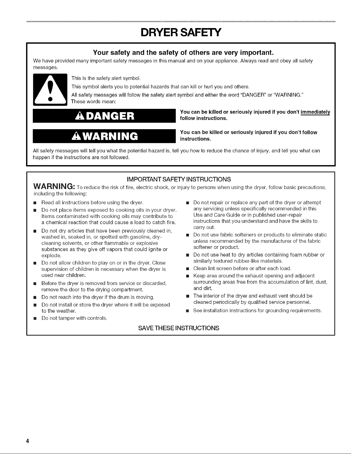
This is the safety alert symbol.
This symbol alerts you to potential hazards that can kill or hurt you and others.
All safety messages will follow the safety alert symbol and either the word "DANGER" or "WARNING."
These words mean:
You can be killed or seriously injured if you don't immediately
follow instructions.
You can be killed or seriously injured if you don't follow
instructions.
All safety messages will tell you what the potential hazard is, tell you how to reduce the chance of injury, and tell you what can
happen if the instructions are not followed.
iMPORTANT SAFETY iNSTRUCTiONS
WARNING: To reduce the risk of fire, electric shock, or injury to persons when using the dryer, follow basic precautions,
including the following:
[] Read all instructions before using the dryer.
[] Do not place items exposed to cooking oils in your dryer.
Items contaminated with cooking oils may contribute to
a chemical reaction that could cause a load to catch fire.
[] Do not dry articles that have been previously cleaned in,
washed in, soaked in, or spotted with gasoline, dry-
cleaning solvents, or other flammable or explosive
substances as they give off vapors that could ignite or
explode.
[] Do not allow children to play on or in the dryer. Close
supervision of children is necessary when the dryer is
used near children.
[] Before the dryer is removed from service or discarded,
remove the door to the drying compartment.
[] Do not reach into the dryer if the drum is moving.
[] Do not install or store the dryer where it will be exposed
to the weather.
[] Do not tamper with controls.
SAVE THESE iNSTRUCTiONS
[] Do not repair or replace any part of the dryer or attempt
any servicing unless specifically recommended in this
Use and Care Guide or in published user-repair
instructions that you understand and have the skills to
carry out.
[] Do not use fabric softeners or products to eliminate static
unless recommended by the manufacturer of the fabric
softener or product.
[] Do not use heat to dry articles containing foam rubber or
similarly textured rubber-like materials.
[] Clean lint screen before or after each load.
[] Keep area around the exhaust opening and adjacent
surrounding areas free from the accumulation of lint, dust,
and dirt.
[] The interior of the dryer and exhaust vent should be
cleaned periodically by qualified service personnel.
[] See installation instructions for grounding requirements.
INSTALLATION INSTRUCTIONS
Gather the required tools and parts before starting installation.
Read and follow the instructions provided with any tools listed
here.
• Flat-blade screwdriver • Vent clamps
• #2 Phillips screwdriver • Caulking gun and
• Adjustable wrench that
opens to 1" (2.54 cm) or new exhaust vent)
hex-head socket wrench • Tin snips (new vent
(for adjusting dryer feet) installations)
• Wire stripper (for direct • 1/4"nut driver or socket
wire installations) wrench (recommended)
• Level • Tape measure
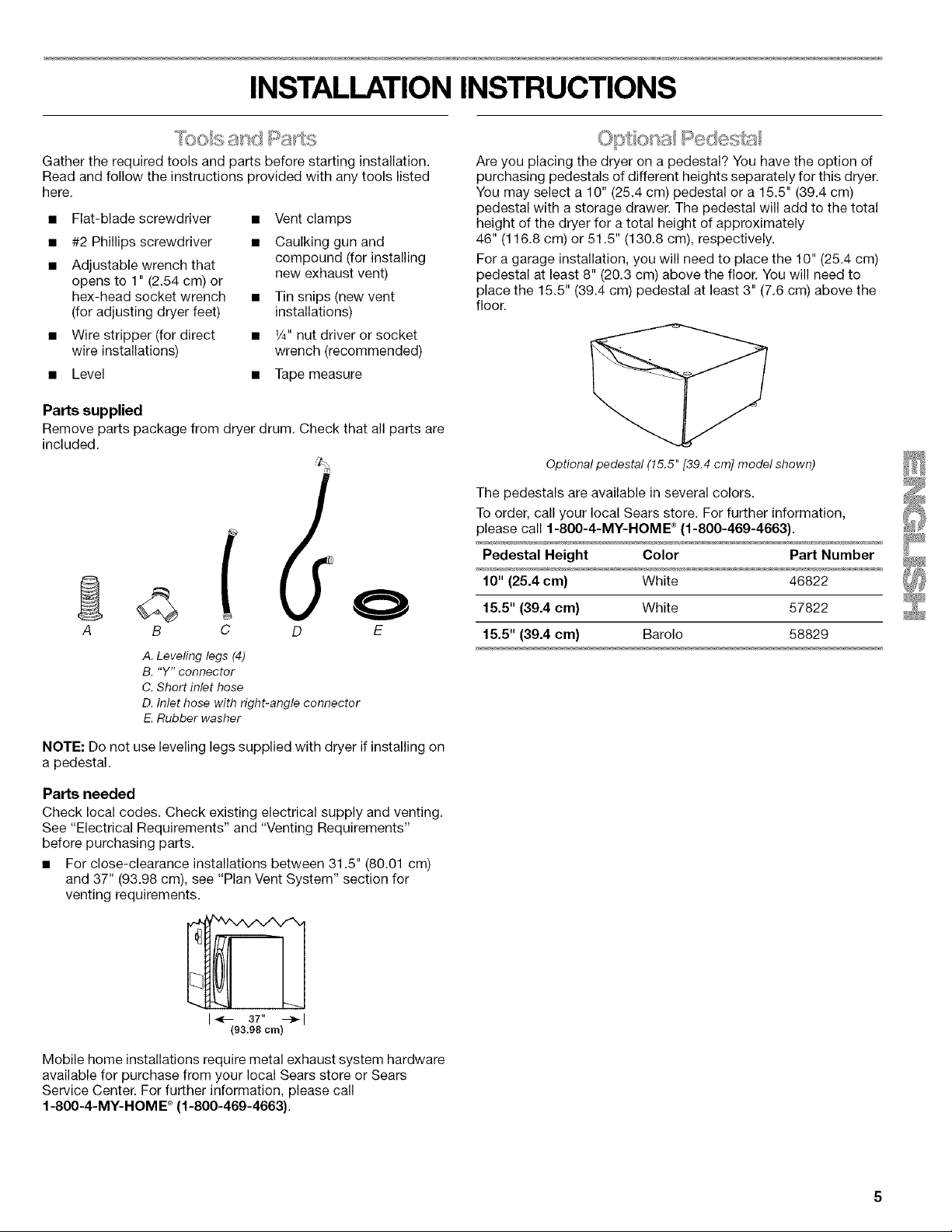
Parts supplied
Remove parts package from dryer drum. Check that all parts are
included.
compound (for installing
o+ a Redes:
Are you placing the dryer on a pedestal? You have the option of
purchasing pedestals of different heights separately for this drye£
You may select a 10" (25.4 cm) pedestal or a 15.5" (39.4 cm)
pedestal with a storage drawer. The pedestal will add to the total
height of the dryer for a total height of approximately
46" (116.8 cm) or 51.5" (130.8 cm), respectively.
For a garage installation, you will need to place the 10" (25.4 cm)
pedestal at least 8" (20.3 cm) above the floor. You will need to
place the 15.5" (39.4 cm) pedestal at least 3" (7.6 cm) above the
floor.
Optional pedestal (15.5" [39.4 cm] model shown)
The pedestals are available in several colors.
To order, call your local Sears store. For further information,
please call 1-800-4-MY-HOME _(1-800-469-4663).
Pedestal Height Color Part Number
10" {25.4 era} White 46822
A B C D E
A. Leveling legs (4)
B. "Y" connector
C. Short inlet hose
D. Inlet hose with right-angle connector
E.Rubber washer
NOTE: Do not use leveling legs supplied with dryer if installing on
a pedestal.
Parts needed
Check local codes. Check existing electrical supply and venting.
See "Electrical Requirements" and "Venting Requirements"
before purchasing parts.
• For close-clearance installations between 31.5" (80.01 cm)
and 37" (93.98 cm), see "Plan Vent System" section for
venting requirements.
I_- 37" --_1
(93.98 cm)
Mobile home installations require metal exhaust system hardware
available for purchase from your local Sears store or Sears
Service Center. For further information, please call
1-800-4-MY-HOM E®(1-800-469-4663).
15.5" (39.4 cm) White 57822
15.5" (39.4 cm) Barolo 58829
ExplosionHazard
Keep flammable materials and vapors, such as
gasoline, away from dryer.
Place dryer at least 18 inches (46 cm) above the floor
for a garage installation.
Failure to do so can result in death, explosion, or fire.
You will need
• A location that allows for proper exhaust installation. See
"Venting Requirements."
• A separate 30-amp circuit.
• If you are using a power supply cord, a grounded electrical
outlet located within 2 ft (61 cm) of either side of the dryer.
See "Electrical Requirements."
• A sturdy floor to support the total dryer weight of 200 Ibs
(90.7 kg). The combined weight of a companion appliance
should also be considered.
Cold water faucets located within 4 ft (1.2 m) of the water fill
valves, and water pressure of 20-100 psi (137.9-689,6 kPa).
You may use the water supply for your washer using the "Y"
connector and short hose (if needed) which are provided.
• 20-100 psi (138-690 kPa) for best performance.
A level floor with a maximum slope of 1" (2.5 cm) under entire
dryer. (If slope is greater than 1" [2.5 cm], install Extended
Dryer Feet Kit, Part Number 279810.) Clothes may not tumble
properly and automatic sensor cycles may not operate
correctly if dryer is not level.
• For a garage installation, you will need to place the dryer at
least 18" (46 cm) above the floor. Ifyou are using a pedestal,
you will need 18" (46 cm) to the bottom of the dryer.
Do not operate your dryer at temperatures below 45°F (7°C). At
lower temperatures, the dryer might not shut off at the end of an
automatic cycle. Drying times can be extended.
The dryer must not be installed or stored in an area where it will
be exposed to water and/or weather.
Check code requirements. Some codes limit, or do not permit,
installation of the dryer in garages, closets, mobile homes, or
sleeping quarters. Contact your local building inspector.
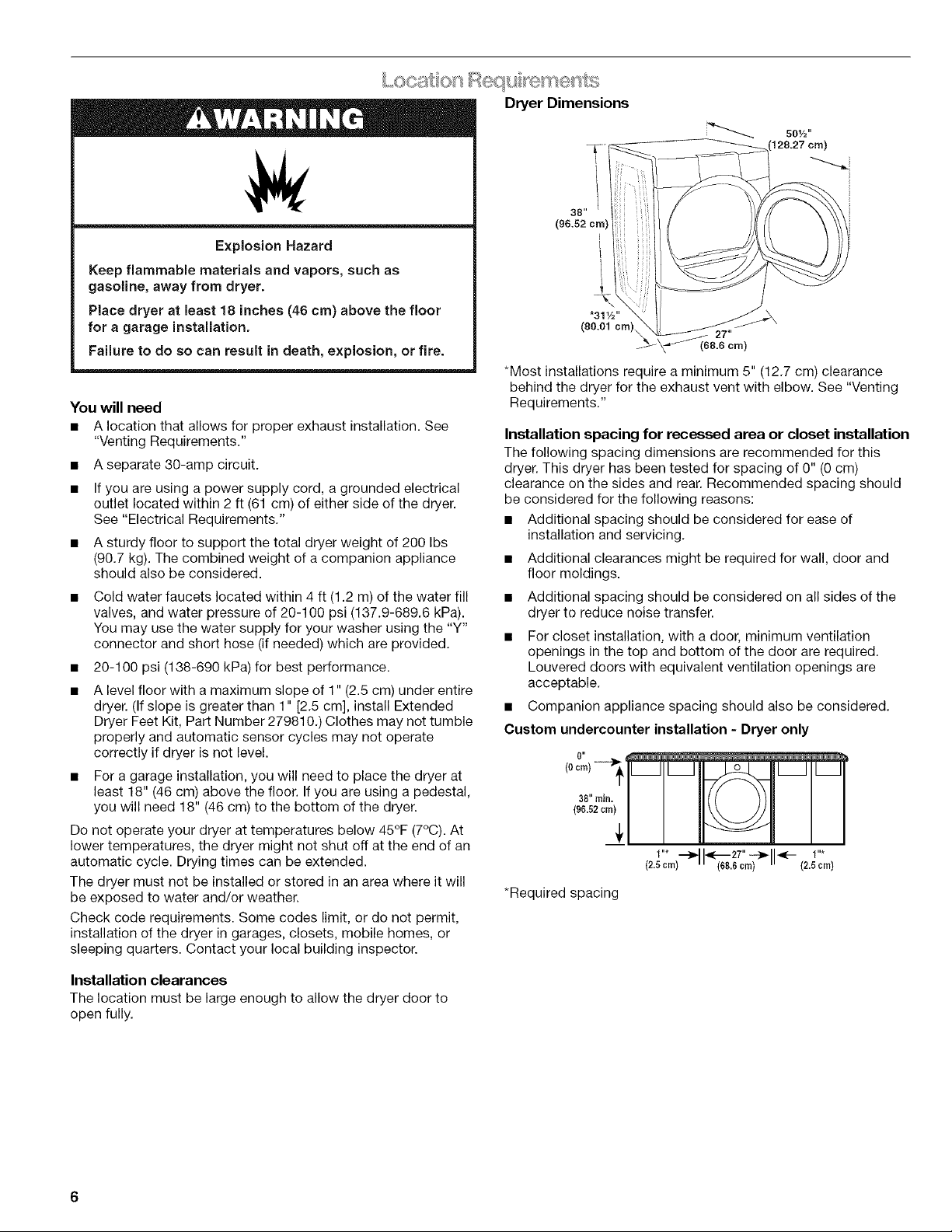
Dryer Dimensions
501/2,,
129.27 cm)
39"
(96.52 cm I
L
!
!
,311/2"
(80.01 cm)
*Most installations require a minimum 5" (12.7 cm) clearance
behind the dryer for the exhaust vent with elbow. See "Venting
Requirements."
Installation spacing for recessed area or closet installation
The following spacing dimensions are recommended for this
dryer. This dryer has been tested for spacing of 0" (0 cm)
clearance on the sides and rear. Recommended spacing should
be considered for the following reasons:
• Additional spacing should be considered for ease of
installation and servicing.
• Additional clearances might be required for wall, door and
floor moldings.
• Additional spacing should be considered on all sides of the
dryer to reduce noise transfer.
For closet installation, with a door, minimum ventilation
openings in the top and bottom of the door are required.
Louvered doors with equivalent ventilation openings are
acceptable.
• Companion appliance spacing should also be considered.
Custom undercounter installation - Dryer only
0"
(96.52 c
38" rninr_;
1"* ,_ _._27"-.-._ _:- 1"*
(2.5 crn) m i (68.6 cm) ii (2.5 crn)
*Required spacing
27"
(68.6 cm)
Installation clearances
The location must be large enough to allow the dryer door to
open fully.
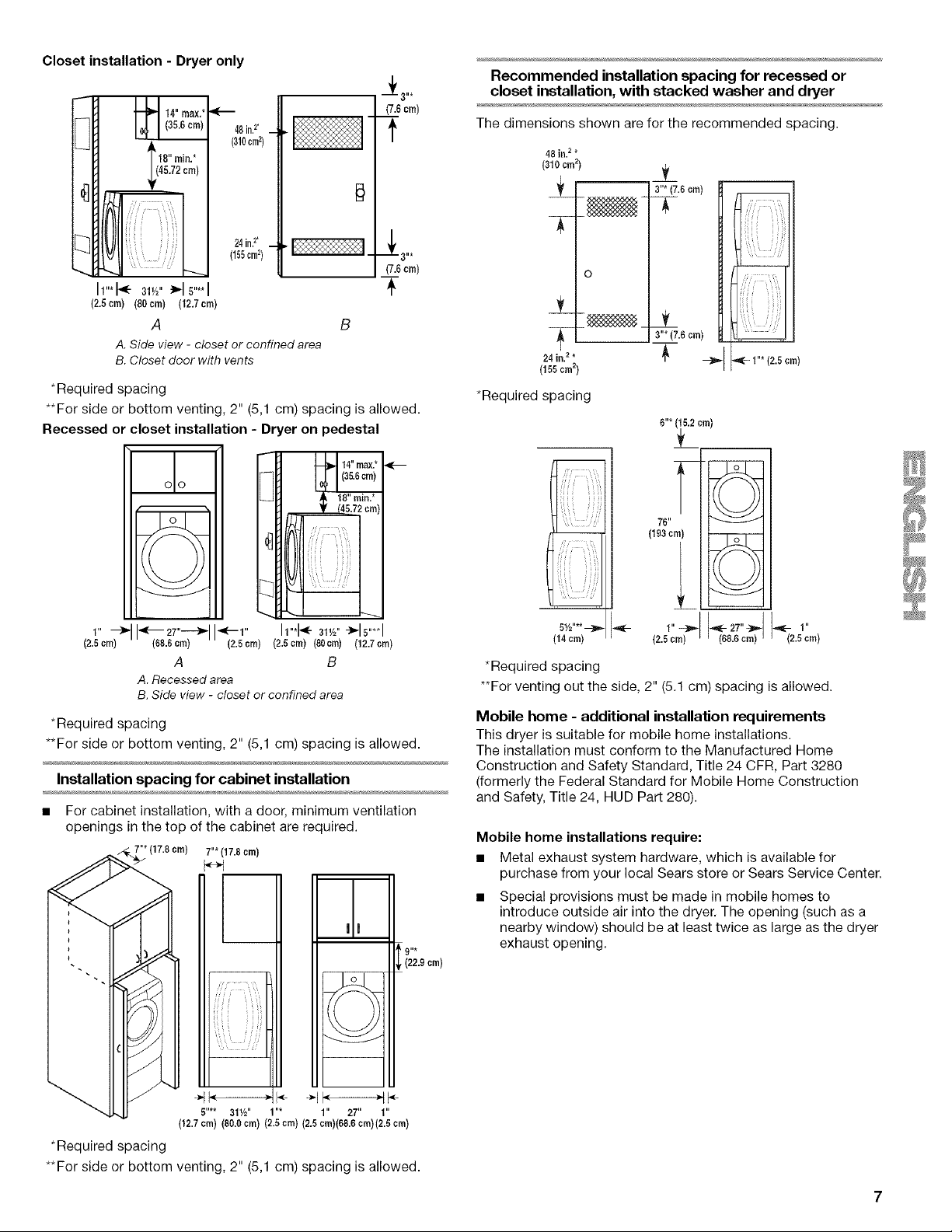
Closet installation - Dryer only
Lt 1-1,4.max''--
L41 (35.6cm) 48in?*(310cm2)
r.,l | 18" rain.*
24in,2.
(155crn2)
h"q<- 31v_"_16....
(2,6crn) (60cm) (12,7cm)
A
A.Side view - closet or confined area
B.Closet door with vents
*Required spacing
**For side or bottom venting, 2" (5,1 cm) spacing is allowed.
Recessed or closet installation - Dryer on pedestal
(7.6cm)
f
- _-3"*
(7.6cm)
+
H
eel
Recommended installation spacing for recessed or
closet installation, with stacked washer and dryer
The dimensions shown are for the recommended spacing.
48 in. 2 *
(310 cm 2)
3"*(7.6 crn)
T
o
__ __
24 in.2*
(155crn2)
*Required spacing
m
_ii,_IIIIIIIIii'_,_ii__
_i_';!__i__i_ '_i__!_i_
3"* (7.6 cm)
'_ --_, ,_- I"* (2.5crn)
6"* (_5.2crn)
76"
(193 crn)
\'_._Jj
(2.5crn)
*Required spacing
**For side or bottom venting, 2" (5,1 cm) spacing is allowed.
Installation spacing for cabinet installation
• For cabinet installation, with a door, minimum ventilation
openings in the top of the cabinet are required.
(68.6cm) (2.Scrn) (2.5crn) (80cm) (12.7crn)
A B
A.Recessedarea
B.Side view - closet or confined area
" • 7"*(17.8 crn)
m) 5"**--91½" 1"* 1" 27" 1"
h"*_ 3w2"-_ls"**l
9"*
(22.9 crn)
5½"**--]P-
(14 cm)
*Required spacing
**For venting out the side, 2" (5.1 cm) spacing is allowed.
Mobile home - additional installation requirements
This dryer is suitable for mobile home installations.
The installation must conform to the Manufactured Home
Construction and Safety Standard, Title 24 CFR, Part 3280
(formerly the Federal Standard for Mobile Home Construction
and Safety, Title 24, HUD Part 280).
Mobile home installations require:
• Metal exhaust system hardware, which is available for
purchase from your local Sears store or Sears Service Center.
Special provisions must be made in mobile homes to
introduce outside air into the dryer. The opening (such as a
nearby window) should be at least twice as large as the dryer
exhaust opening.
1"-_ ,._ -,_-27"_ _ 1"
(2.5 era) 68.6 cm 2.5 cm
(12.7 cra) (89.0 cm) (2.5 cm) (2.5 cra)(6&6 cra)(2.5 cra)
*Required spacing
**For side or bottom venting, 2" (5,1 cm) spacing is allowed.
It is your responsibility
• Tocontact a qualified electrical installer.
• To be sure that the electrical connection is adequate and in
conformance with the National Electrical Code, ANSl/NFPA
70-latest edition and all local codes and ordinances.
The National Electric Code requires a 4-wire supply
connection for homes built after 1996, dryer circuits involved
in remodeling after 1996, and all mobile home installations.
A copy of the above code standards can be obtained from:
National Fire Protection Association, One Batterymarch Park,
Quincy, MA 02269.
To supply the required 3 or 4 wire, single phase, 120/240 volt,
60 Hz., AC only electrical supply (or 3 or 4 wire, 120/208 volt
electrical supply, if specified on the serial/rating plate) on a
separate 30-amp circuit, fused on both sides of the line. A
time-delay fuse or circuit breaker is recommended. Connect
to an individual branch circuit. Do not have a fuse in the
neutral or grounding circuit.
• Do not use an extension cord.
• If codes permit and a separate ground wire is used, it is
recommended that a qualified electrician determine that the
ground path is adequate.
Electrical Connection
To properly install your dryer, you must determine the type of
electrical connection you will be using and follow the instructions
provided for it here.
• If local codes do not permit the connection of a neutral
ground wire to the neutral wire, see "Optional 3-wire
connection" in the "Electrical Connection" section.
This dryer is manufactured ready to install with a 3-wire
electrical supply connection. The neutral ground wire is
permanently connected to the neutral conductor (white wire)
within the dryer. Ifthe dryer is installed with a 4-wire electrical
supply connection, the neutral ground wire must be removed
from the external ground conductor screw (green screw), and
secured under the neutral terminal (center or white wire) of
the terminal block. When the neutral ground wire is secured
under the neutral terminal (center or white wire) of the
terminal block, the dryer cabinet is isolated from the neutral
conductor.
A 4-wire power supply connection must be used when the
appliance is installed in a location where grounding through
the neutral conductor is prohibited. Grounding through the
neutral is prohibited for (1) new branch-circuit installations,
(2) mobile homes, (3) recreational vehicles, and (4) areas
where local codes prohibit grounding through the neutral
conductors.
If using a power supply cord:
Use a UL listed power supply cord kit marked for use with
clothes dryers. The kit should contain:
• A UL listed 30-amp power supply cord, rated
120/240 volt minimum. The cord should be type SRD or
SRDT and be at least 4 ft (1.22 m) long. The wires that
connect to the dryer must end in ring terminals or spade
terminals with upturned ends.
• A UL listed strain relief.
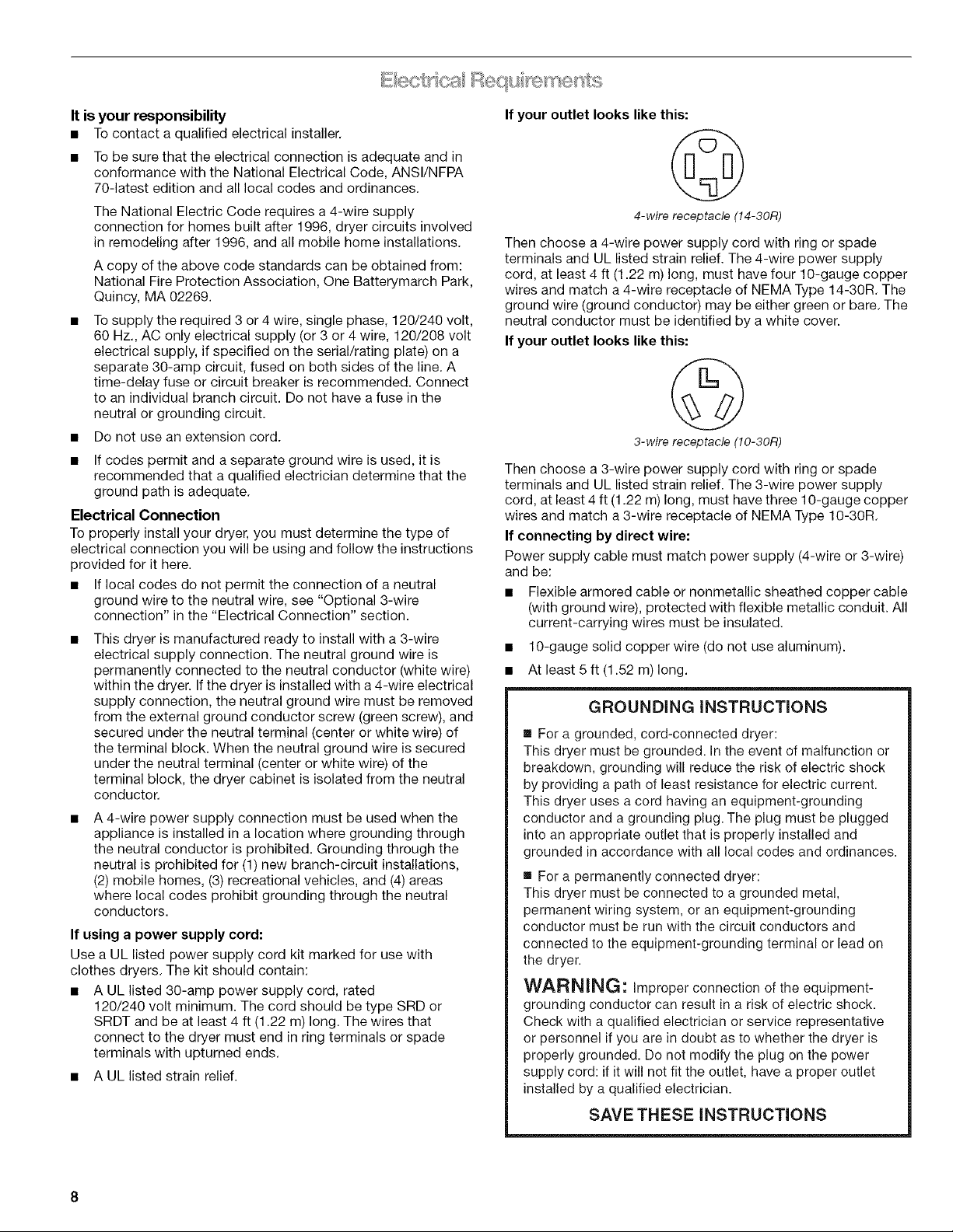
If your outlet looks like this:
4-wire receptacle (!4-30R)
Then choose a 4-wire power supply cord with ring or spade
terminals and UL listed strain relief. The 4-wire power supply
cord, at least 4 ft (1.22 m) long, must have four 10-gauge copper
wires and match a 4-wire receptacle of NEMA Type 14-30R. The
ground wire (ground conductor) may be either green or bare. The
neutral conductor must be identified by a white cover.
If your outlet looks like this:
3-wire receptacle (10-30R)
Then choose a 3-wire power supply cord with ring or spade
terminals and UL listed strain relief. The 3-wire power supply
cord, at least 4 ft (1.22 m) long, must have three 10-gauge copper
wires and match a 3-wire receptacle of NEMA Type 10-30R.
If connecting by direct wire:
Power supply cable must match power supply (4-wire or 3-wire)
and be:
• Flexible armored cable or nonmetallic sheathed copper cable
(with ground wire), protected with flexible metallic conduit. All
current-carrying wires must be insulated.
• 10-gauge solid copper wire (do not use aluminum).
• At least 5 ft (1.52 m) long.
GROUNDING INSTRUCTIONS
• For a grounded, cord-connected dryer:
This dryer must be grounded. In the event of malfunction or
breakdown, grounding will reduce the risk of electric shock
by providing a path of least resistance for electric current.
This dryer uses a cord having an equipment-grounding
conductor and a grounding plug. The plug must be plugged
into an appropriate outlet that is properly installed and
grounded in accordance with all local codes and ordinances.
• For a permanently connected dryer:
This dryer must be connected to a grounded metal,
permanent wiring system, or an equipment-grounding
conductor must be run with the circuit conductors and
connected to the equipment-grounding terminal or lead on
the dryer.
WARNING: improper connection of the equipment-
grounding conductor can result in a risk of electric shock.
Check with a qualified electrician or service representative
or personnel if you are in doubt as to whether the dryer is
properly grounded. Do not modify the plug on the power
supply cord: if it will not fit the outlet, have a proper outlet
installed by a qualified electrician.
SAVE THESE INSTRUCTIONS
Power Supply Cord
Direct Wire
Fire Hazard
Use a new UL listed 30 amp power supply cord.
Use a UL listed strain relief.
Disconnect power before making electrical connections.
Connect neutral wire (white or center wire) to center
terminal (silver).
Ground wire (green or bare wire) must be connected to
green ground connector.
Connect remaining 2 supply wires to remaining
2 terminals (gold).
Securely tighten all electrical connections.
Failure to do so can result in death, fire, or
electrical shock.
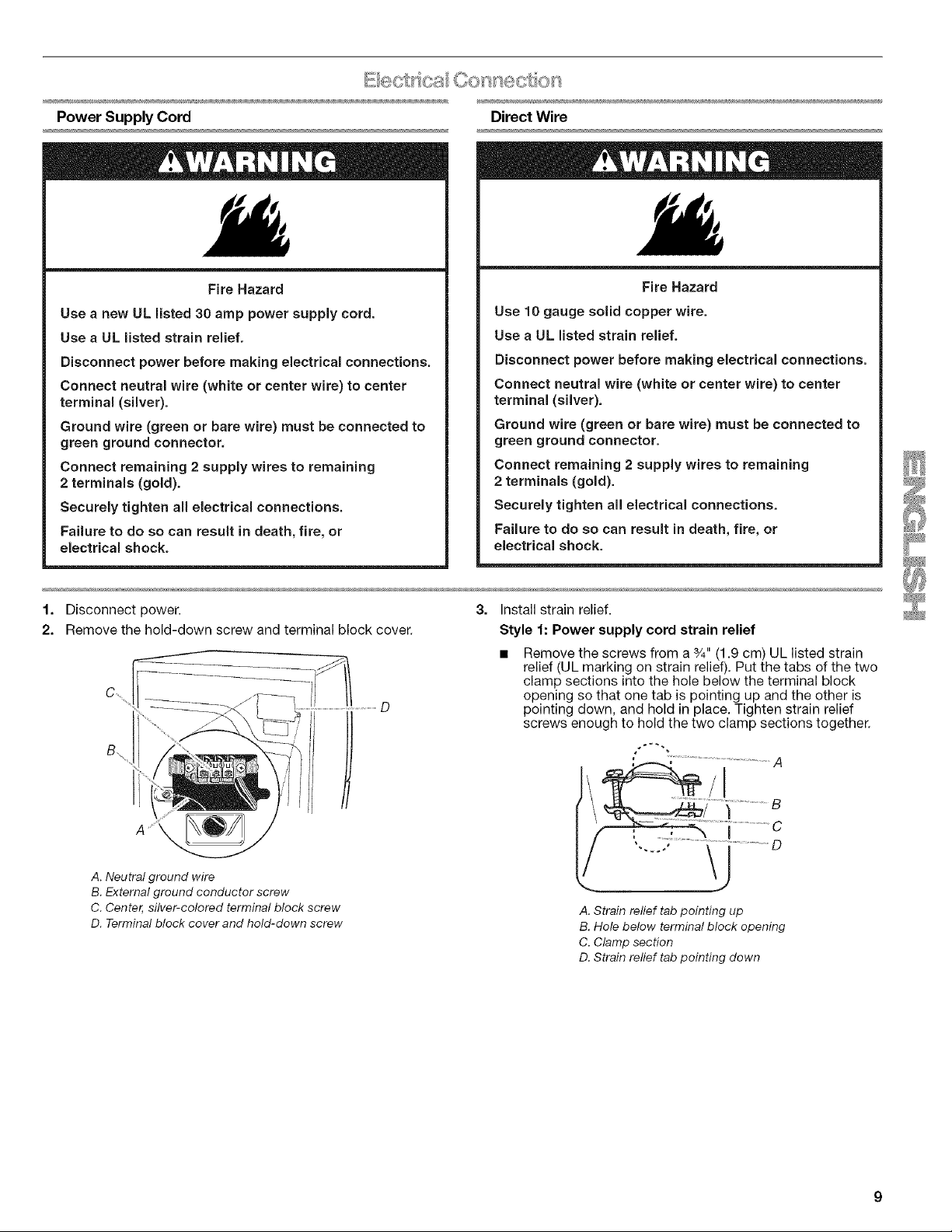
1. Disconnect power.
2. Remove the hold-down screw and terminal block cover.
B
Fire Hazard
Use 10 gauge solid copper wire.
Use a UL listed strain relief.
Disconnect power before making electrical connections.
Connect neutral wire (white or center wire) to center
terminal (silver).
Ground wire (green or bare wire) must be connected to
green ground connector.
Connect remaining 2 supply wires to remaining
2 terminals (gold).
Securely tighten all electrical connections.
Failure to do so can result in death, fire, or
electrical shock.
3. Install strain relief.
Style 1: Power supply cord strain relief
Remove the screws from a 3/4"(1.9 cm) UL listed strain
relief (UL marking on strain relief). Put the tabs of the two
clamp sections into the hole below the terminal block
opening so that one tab is pointing up and the other is
pointing down, and hold in place. Tighten strain relief
screws enough to hold the two clamp sections together.
A. Neutral ground wire
B. External ground conductor screw
C. Center, silver-colored terminal block screw
D. Terminal block cover and hold-down screw
;......................i ...........................A
A. Strain relief tab pointing up
B. Hole below terminal block opening
C. Clamp section
D. Strain relief tab pointing down
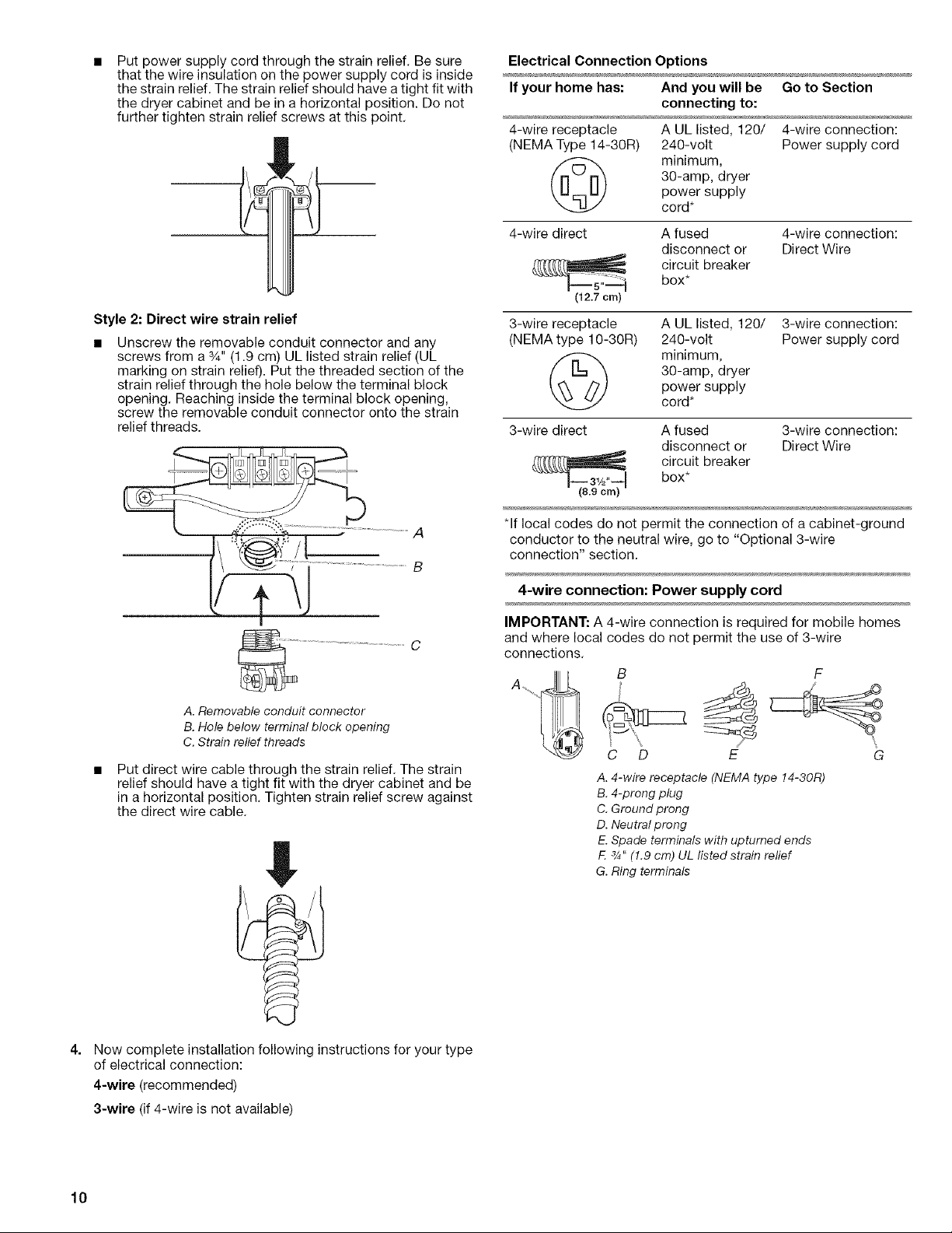
Put power supply cord through the strain relief. Be sure
that the wire insulation on the power supply cord is inside
the strain relief. The strain relief should have atight fit with
the dryer cabinet and be in a horizontal position. Do not
further tighten strain relief screws at this point.
Style 2: Direct wire strain relief
Unscrew the removable conduit connector and any
screws from a %" (1.9 cm) UL listed strain relief (UL
marking on strain relief). Put the threaded section of the
strain relief through the hole below the terminal block
opening. Reaching inside the terminal block opening,
screw the removable conduit connector onto the strain
relief threads.
Electrical Connection Options
If your home has: And you will be Go to Section
connecting to:
4-wire receptacle A UL listed, 120/ 4-wire connection:
(NEMA Type 14-30R) 240-volt Power supply cord
30-amp, dryer
power supply
minimum,
cord*
4-wire direct A fused 4-wire connection:
disconnect or Direct Wire
circuit breakerbox*
(12.7 cm)
3-wire receptacle A UL listed, 120/
(NEMA type 10-30R) 240-volt
3-wire connection:
Power supply cord
30-amp, dryer
power supply
minimum,
cord*
3-wire direct A fused 3-wire connection:
disconnect or Direct Wire
box*
circuit breaker
A. Removable conduit connector
B. Hole below terminal block opening
C. Strain relief threads
Put direct wire cable through the strain relief. The strain
relief should have a tight fit with the dryer cabinet and be
in a horizontal position. Tighten strain relief screw against
the direct wire cable.
*If local codes do not permit the connection of a cabinet-ground
conductor to the neutral wire, go to "Optional 3-wire
connection" section.
4-wire connection: Power supply cord
IMPORTANT: A 4-wire connection is required for mobile homes
and where local codes do not permit the use of 3-wire
connections.
A. /
C D E G
A. 4-wire receptacle (NEMA type 14-30R)
B. 4-prong plug
C. Ground prong
D. Neutral prong
E. Spade terminals with upturned ends
E a_,,(1.9 cm) UL listedstrain relief
G. Ring terminals
4.
Now complete installation following instructions for your type
of electrical connection:
4-wire (recommended)
3-wire (if 4-wire is not available)
10
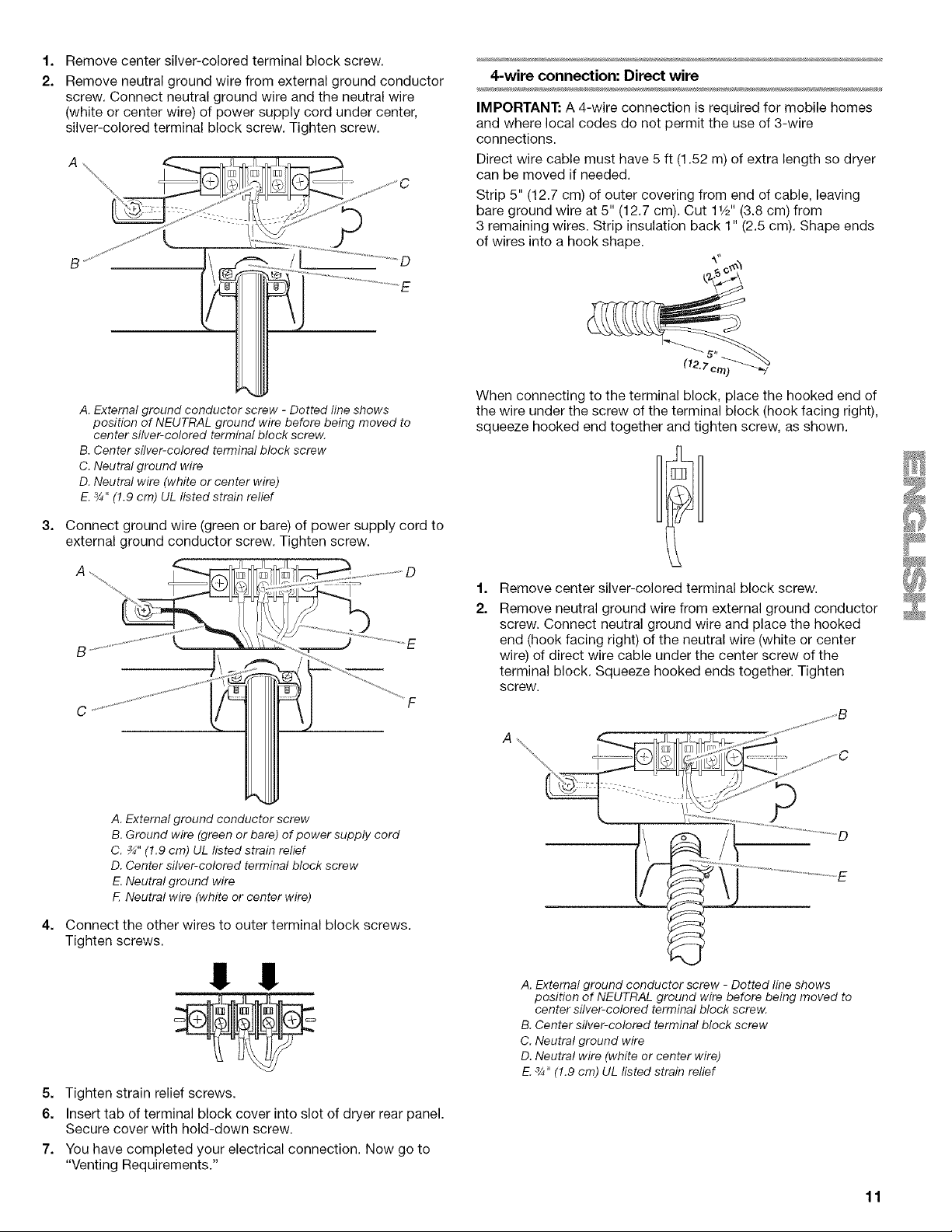
1,
Remove center silver-colored terminal block screw.
2.
Remove neutral ground wire from external ground conductor
screw. Connect neutral ground wire and the neutral wire
(white or center wire) of power supply cord under center,
silver-colored terminal block screw. Tighten screw.
\ I L
A \ _ _qf[r_:11__
4-wire connection: Direct wire
IMPORTANT: A 4-wire connection is required for mobile homes
and where local codes do not permit the use of 3-wire
connections.
Direct wire cable must have 5 ft (1.52 m) of extra length so dryer
can be moved if needed.
Strip 5" (12.7 cm) of outer covering from end of cable, leaving
bare ground wire at 5" (12.7 cm). Cut 11/2'' (3.8 cm) from
3 remaining wires. Strip insulation back 1" (2.5 cm). Shape ends
of wires into a hook shape.
(12,7 c
A. Externalground conductor screw - Dotted line shows
position of NEUTRAL ground wire before being moved to
center silver-colored terminalblock screw.
B.Center silver-colored terminalblock screw
C. Neutralground wire
D. Neutral wire (white or center wire)
E.3/4"(1.9 cm) UL Iisted strain relief
3,
Connect ground wire (green or bare) of power supply cord to
external ground conductor screw. Tighten screw.
A. External ground conductor screw
B. Ground wire (green or bare) of power supply cord
C. _" (1.9 cm) UL listed strain relief
D. Center silver-colored terminal block screw
E,Neutral ground wire
E Neutral wire (white or center wire)
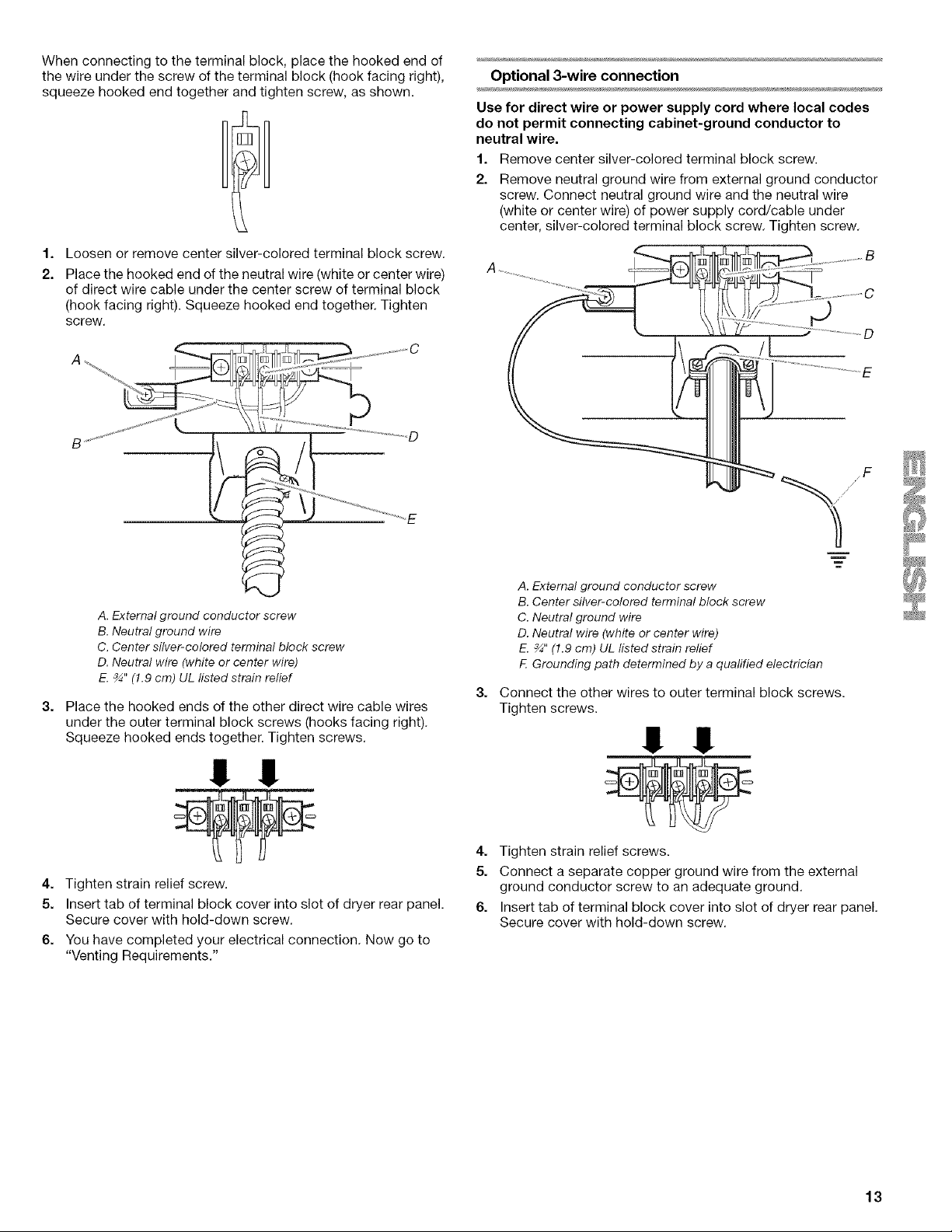
When connecting to the terminal block, place the hooked end of
the wire under the screw of the terminal block (hook facing right),
squeeze hooked end together and tighten screw, as shown.
1,
Remove center silver-colored terminal block screw.
2.
Remove neutral ground wire from external ground conductor
screw. Connect neutral ground wire and place the hooked
end (hook facing right) of the neutral wire (white or center
wire) of direct wire cable under the center screw of the
terminal block. Squeeze hooked ends together. Tighten
screw.
4,
Connect the other wires to outer terminal block screws.
Tighten screws.
!! !!
5. Tighten strain relief screws.
6. Insert tab of terminal block cover into slot of dryer rear panel.
Secure cover with hold-down screw.
7. You have completed your electrical connection. Now go to
"Venting Requirements."
A. External ground conductor screw - Dotted line shows
position of NEUTRAL ground wire before being moved to
center silver-colored terminal block screw.
B. Center silver-colored terminal block screw
C. Neutral ground wire
D. Neutral wire (white or center wire)
E. 3/4"(1.9 cm) UL listed strain relief
11
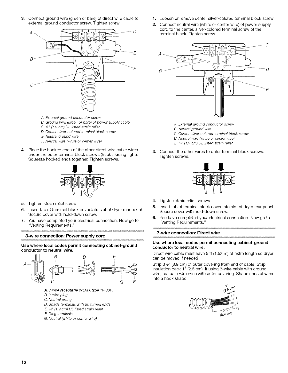
3.
Connect ground wire (green or bare) of direct wire cable to
external ground conductor screw. Tighten screw.
B
A. External ground conductor screw
B. Ground wire (green or bare) of power supply cable
C. 3/4"(1.9 cm) UL listed strain relief
D. Center silver-colored terminal block screw
E. Neutral ground wire
F Neutral wire (white or center wire)
4. Place the hooked ends of the other direct wire cable wires
under the outer terminal block screws (hooks facing right).
Squeeze hooked ends together. Tighten screws.
1.
Loosen or remove center silver-colored terminal block screw.
2.
Connect neutral wire (white or center wire) of power supply
cord to the center, silver-colored terminal screw of the
terminal block. Tighten screw.
A. External ground conductor screw
B. Neutral ground wire
C. Center silver-colored terminal block screw
D. Neutral wire (white or center wire)
E. _" (1.9 cm) UL listed strain relief
3. Connect the other wires to outer terminal block screws.
Tighten screws.
!! !!
5. Tighten strain relief screw.
6. Insert tab of terminal block cover into slot of dryer rear panel.
Secure cover with hold-down screw.
7. You have completed your electrical connection. Now go to
"Venting Requirements."
3-wire connection: Power supply cord
Use where local codes permit connecting cabinet-ground
conductor to neutral wire.
B D E
C G F
A. 3-wire receptacle (NEMA type 10-30R)
B. 3-wire plug
C. Neutral prong
D. Spade terminals with up turned ends
E. _" (1.9 cm) UL listed strain relief
F. Ring terminals
G. Neutral (white or center wire)
!! !!
4. Tighten strain relief screws.
5. Insert tab of terminal block cover into slot of dryer rear panel.
Secure cover with hold-down screw.
6. You have completed your electrical connection. Now go to
"Venting Requirements."
3-wire connection: Direct wire
Use where local codes permit connecting cabinet-ground
conductor to neutral wire.
Direct wire cable must have 5 ft (1.52 m) of extra length so dryer
can be moved if needed.
Strip 31/2'' (8.9 cm) of outer covering from end of cable. Strip
insulation back 1" (2.5 cm). If using 3-wire cable with ground
wire, cut bare wire even with outer covering. Shape ends of wires
into a hook shape.
12
When connecting to the terminal block, place the hooked end of
the wire under the screw of the terminal block (hook facing right),
squeeze hooked end together and tighten screw, as shown.
1=
Loosen or remove center silver-colored terminal block screw.
2.
Place the hooked end of the neutral wire (white or center wire)
of direct wire cable under the center screw of terminal block
(hook facing right). Squeeze hooked end together. Tighten
screw.
Optional 3-wire connection
Use for direct wire or power supply cord where local codes
do not permit connecting cabinet-ground conductor to
neutral wire.
1. Remove center silver-colored terminal block screw.
2. Remove neutral ground wire from external ground conductor
screw. Connect neutral ground wire and the neutral wire
(white or center wire) of power supply cord/cable under
center, silver-colored terminal block screw. Tighten screw.
D
A. Externalground conductor screw
B.Neutralground wire
C. Center silver-colored terminal block screw
D. Neutral wire (white or center wire)
E._" (!.9 cm) UL listed strain relief
3,
Place the hooked ends of the other direct wire cable wires
under the outer terminal block screws (hooks facing right).
Squeeze hooked ends together. Tighten screws.
!! !!
4. Tighten strain relief screw.
5. Insert tab of terminal block cover into slot of dryer rear panel.
Secure cover with hold-down screw.
6. You have completed your electrical connection. Now go to
"Venting Requirements."
A. External ground conductor screw
B. Center silver-colored terminal block screw
C. Neutral ground wire
D. Neutral wire (white or center wire)
E. _" (1.9 cm) UL listed strain relief
F. Grounding path determined by a qualified electrician
3,
Connect the other wires to outer terminal block screws.
Tighten screws.
!! !!
4. Tighten strain relief screws.
5. Connect a separate copper ground wire from the external
ground conductor screw to an adequate ground.
6. Insert tab of terminal block cover into slot of dryer rear panel.
Secure cover with hold-down screw.
13
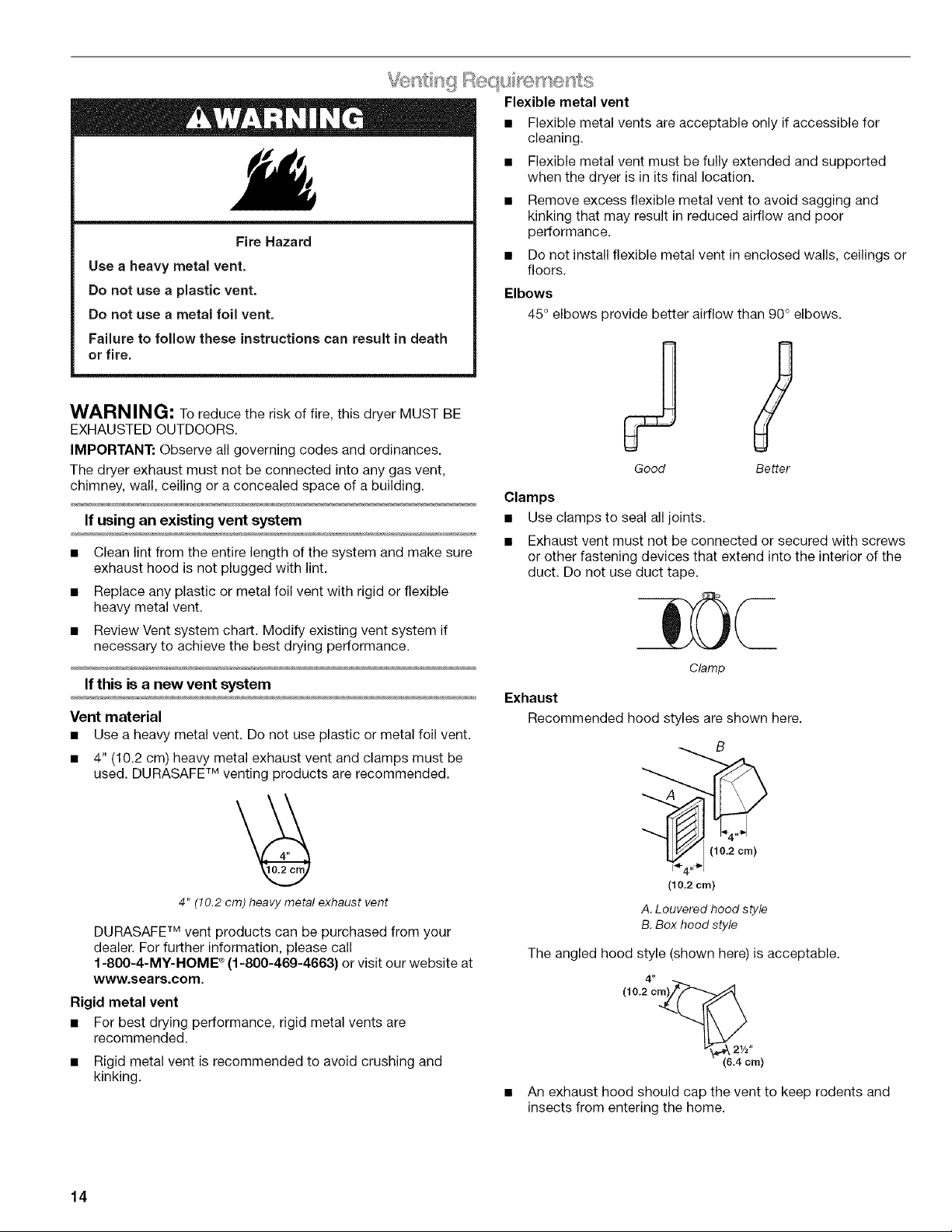
Fire Hazard
Use a heavy metal vent.
Do not use a plastic vent.
Do not use a metal foil vent.
Failure to fellow these instructions can result in death
or fire.
WARNING: To reduce the risk of fire, this dryer MUST BE
EXHAUSTED OUTDOORS.
IMPORTANT: Observe all governing codes and ordinances.
The dryer exhaust must not be connected into any gas vent,
chimney, wall, ceiling or a concealed space of a building.
If using an existing vent system •
• Clean lint from the entire length of the system and make sure
exhaust hood is not plugged with lint.
• Replace any plastic or metal foil vent with rigid or flexible
heavy metal vent.
• Review Vent system chart. Modify existing vent system if
necessary to achieve the best drying performance.
If this is a new vent system
Vent material
• Use a heavy metal vent. Do not use plastic or metal foil vent.
• 4" (10.2 cm) heavy metal exhaust vent and clamps must be
used. DURASAFE TM venting products are recommended.
Flexible metal vent
• Flexible metal vents are acceptable only if accessible for
cleaning.
• Flexible metal vent must be fully extended and supported
when the dryer is in its final location.
• Remove excess flexible metal vent to avoid sagging and
kinking that may result in reduced airflow and poor
performance.
• Do not install flexible metal vent in enclosed walls, ceilings or
floors.
Elbows
45° elbows provide better airflow than 90° elbows.
Good Better
Clamps
Use clamps to seal all joints.
Exhaust vent must not be connected or secured with screws
or other fastening devices that extend into the interior of the
duct. Do not use duct tape.
Clamp
Exhaust
Recommended hood styles are shown here.
B
4" (10.2cm) heavymetal exhaust vent
DURASAFE TM vent products can be purchased from your
dealer. For further information, please call
1-800-4-MY-HOME ®(1-800-469-4663) or visit our website at
www.sears.com,
Rigid metal vent
• For best drying performance, rigid metal vents are
recommended.
• Rigid metal vent is recommended to avoid crushing and
kinking.
14
(10.2 cm)
A.Louveredhood style
B.Box hood style
The angled hood style (shown here) is acceptable.
4"
(10.2 cm)_(_
I/_._ 21/2-
(6.4cm)
An exhaust hood should cap the vent to keep rodents and
insects from entering the home.
Exhaust hood must be at least 12" (30.5 cm) from the ground
or any object that may be in the path of the exhaust (such as
flowers, rocks or bushes, snow line, etc.).
• Do not use an exhaust hood with a magnetic latch.
improper venting can cause moisture and lint to collect
indoors, which may result in:
[] Moisture damage to woodwork, furniture, paint, wallpaper,
carpets, etc.
[] Housecleaning problems and health problems.
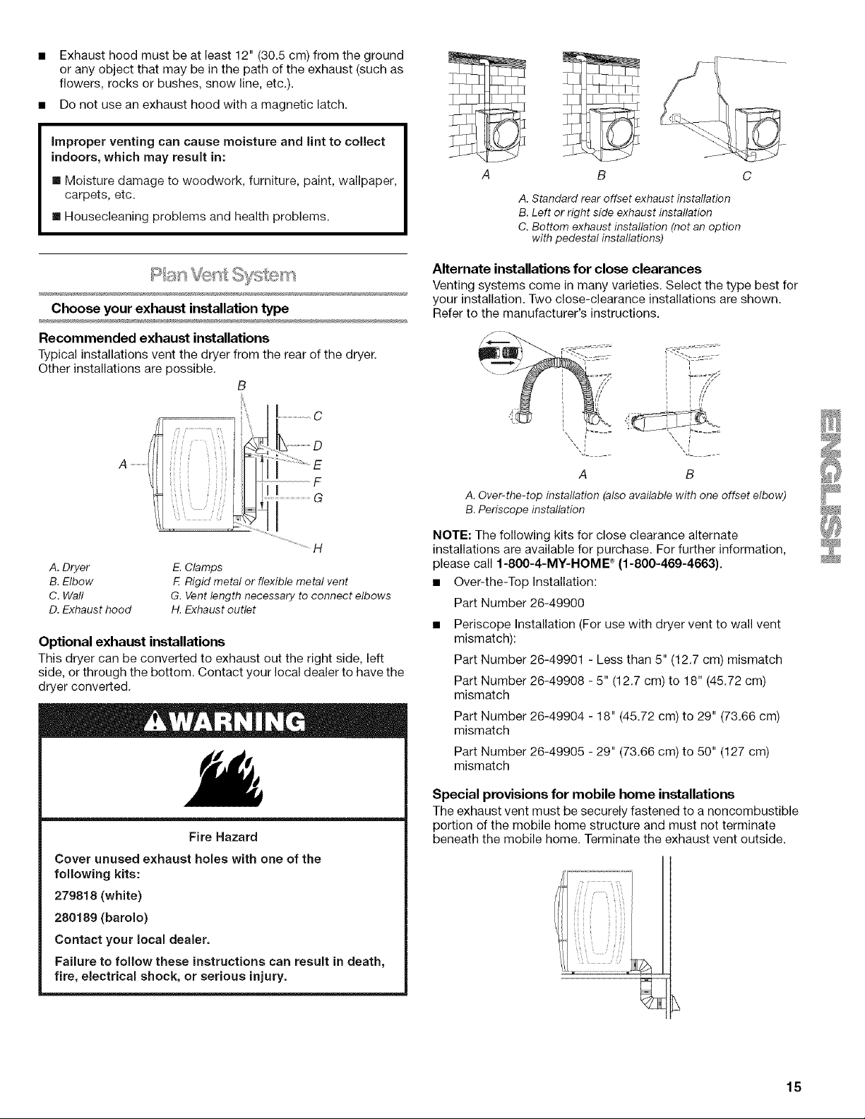
Choose your exhaust installation type
Recommended exhaust installations
Typical installations vent the dryer from the rear of the dryer.
Other installations are possible.
B
A B
A. Standard rear offset exhaust installation
B. Left or right side exhaust installation
C. Bottom exhaust installation (not an option
with pedestal installations)
Alternate installations for close clearances
Venting systems come in many varieties. Select the type best for
your installation. Two close-clearance installations are shown.
Refer to the manufacturer's instructions.
i II
i F //
i /z
J/
A ....................
A. Dryer
B. Elbow
C. Wall
D. Exhaust hood
E. Clamps
F. Rigid metal or flexible metal vent
G. Vent length necessary to connect elbows
H. Exhaust outlet
Optional exhaust installations
This dryer can be converted to exhaust out the right side, left
side, or through the bottom. Contact your local dealer to have the
dryer converted,
Fire Hazard
Cover unused exhaust holes with one of the
following kits:
279818 (white)
280189 (barolo)
Contact your local dealer.
Failure to follow these instructions can result in death,
fire, electrical shock, or serious injury.
A B
A. Over-the-top installation (also available with one offset elbow)
B. Periscope installation
NOTE: The following kits for close clearance alternate
installations are available for purchase. For further information,
please call 1-800-4-MY-HOME ®(f-800-469-4663}.
• Over-the-Top Installation:
Part Number 26-49900
• Periscope Installation (For use with dryer vent to wall vent
mismatch):
Part Number 26-49901 - Less than 5" (12.7 cm) mismatch
Part Number 26-49908 - 5" (12.7 cm) to 18" (45,72 cm)
mismatch
Part Number 26-49904 - 18" (45.72 cm) to 29" (73,66 cm)
mismatch
Part Number 26-49905 - 29" (73.66 cm) to 50" (127 cm)
mismatch
Special provisions for mobile home installations
The exhaust vent must be securely fastened to a noncombustible
portion of the mobile home structure and must not terminate
beneath the mobile home. Terminate the exhaust vent outside.
15
Determine vent path
• Select the route that will provide the straightest and most
direct path outdoors.
• Plan the installation to use the fewest number of elbows and
turns.
• When using elbows or making turns, allow as much room as
possible.
• Bend vent gradually to avoid kinking.
• Use the fewest 90 ° turns possible.
Determine vent length and elbows needed for best
drying performance
• Use the following Vent system chart to determine type of vent
material and hood combinations acceptable to use.
• NOTE: Do not use vent runs longer than those specified in
the Vent system chart. Exhaust systems longer than those
specified will:
• Shorten the life of the dryer.
• Reduce performance, resulting in longer drying times and
increased energy usage.
The Vent system chart provides venting requirements that will
help to achieve the best drying performance.
Excessive Weight Hazard
Use two or more people to move and install dryer.
Failure to do so can result in back or other injury.
1. To protect the floor, use a large flat piece of cardboard from
the dryer carton. Place cardboard under the entire back edge
of the dryer.
2. Firmly grasp the body of the dryer (not the console panel).
Gently lay the dryer on the cardboard. See illustration.
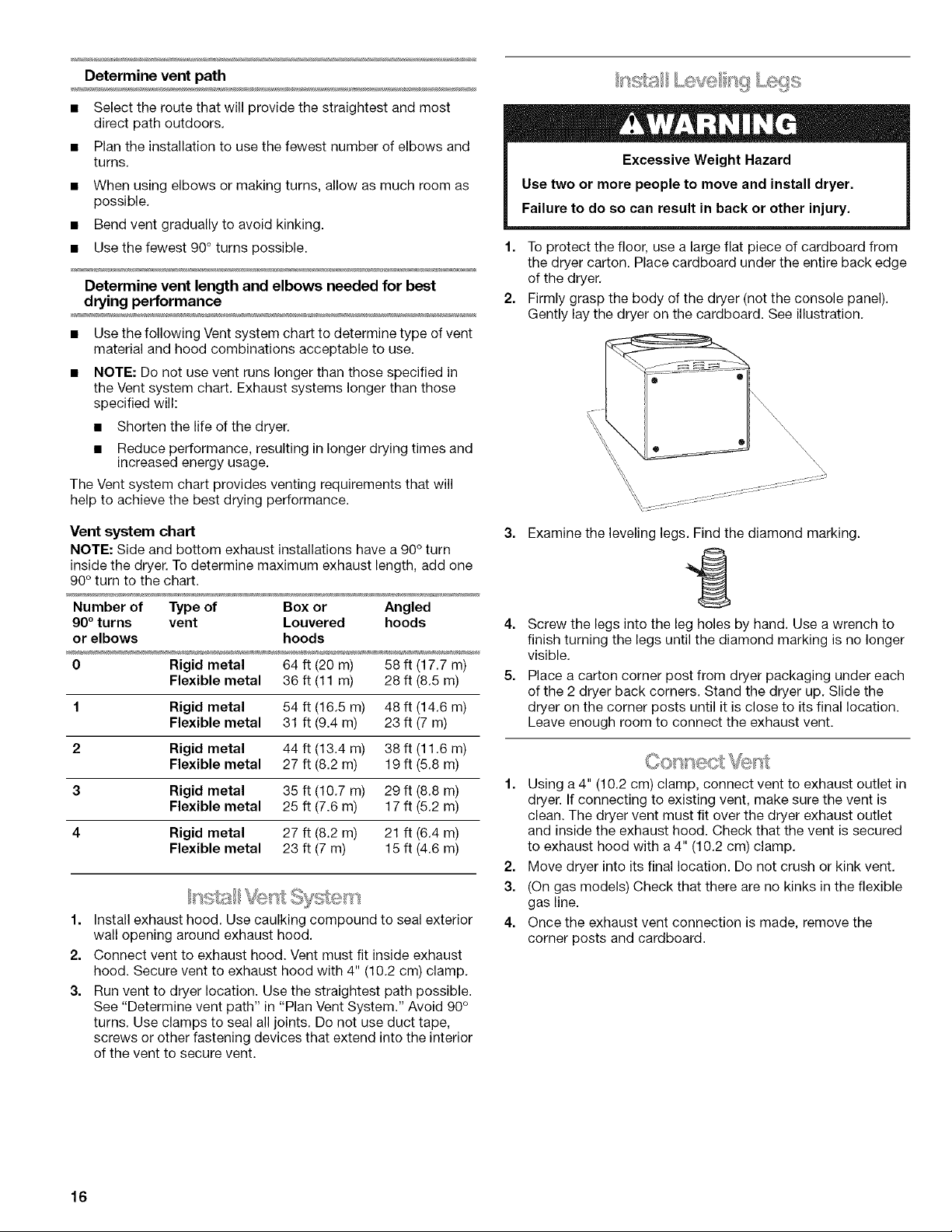
Vent system chart
NOTE: Side and bottom exhaust installations have a 90° turn
inside the dryer. To determine maximum exhaust length, add one
90° turn to the chart.
Number of Type of Box or Angled
90° turns vent Louvered hoods
or elbows hoods
0 Rigid metal 64 ft (20 m) 58 ft (17.7 m)
Flexible metal 36 ft (11 m) 28 ft (8.5 m)
1 Rigid metal 54 ft (16.5 m) 48 ft (14.6 m)
Flexible metal 31 ft (9.4 m) 23 ft (7 m)
2 Rigid metal 44 ft (13.4 m) 38 ft (11.6 m)
Flexible metal 27 ft (8.2 m) 19 ft (5.8 m)
3 Rigid metal 35 ft (10.7 m) 29 ft (8.8 m)
Flexible metal 25 ft (7.6 m) 17 ft (5.2 m)
4 Rigid metal 27 ft (8.2 m) 21 ft (6.4 m)
Flexible metal 23 ft (7 m) 15 ft (4.6 m)
1.
Install exhaust hood. Use caulking compound to seal exterior
wall opening around exhaust hood.
2.
Connect vent to exhaust hood. Vent must fit inside exhaust
hood. Secure vent to exhaust hood with 4" (10.2 cm) clamp.
3.
Run vent to dryer location. Use the straightest path possible.
See "Determine vent path" in "Plan Vent System." Avoid 90°
turns. Use clamps to seal alljoints. Do not use duct tape,
screws or other fastening devices that extend into the interior
of the vent to secure vent.
3.
Examine the leveling legs. Find the diamond marking.
11
4. Screw the legs into the leg holes by hand. Use a wrench to
finish turning the legs until the diamond marking is no longer
visible.
5. Place a carton corner post from dryer packaging under each
of the 2 dryer back corners. Stand the dryer up. Slide the
dryer on the corner posts until it is close to its final location.
Leave enough room to connect the exhaust vent.
1. Using a 4" (10.2 cm) clamp, connect vent to exhaust outlet in
dryer. If connecting to existing vent, make sure the vent is
clean. The dryer vent must fit over the dryer exhaust outlet
and inside the exhaust hood. Check that the vent is secured
to exhaust hood with a 4" (10.2 cm) clamp.
2. Move dryer into its final location. Do not crush or kink vent.
3. (On gas models) Check that there are no kinks in the flexible
gas line.
4. Once the exhaust vent connection is made, remove the
corner posts and cardboard.
16
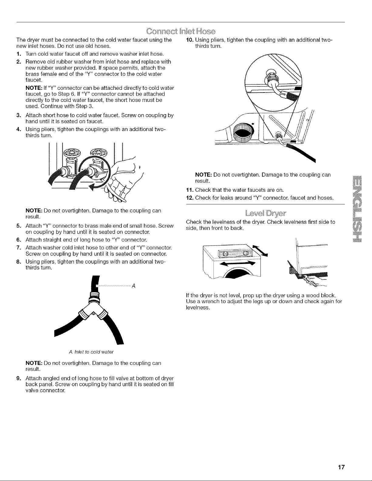
The dryer must be connected to the cold water faucet using the
new inlet hoses. Do not use old hoses.
1. Turn cold water faucet off and remove washer inlet hose.
2. Remove old rubber washer from inlet hose and replace with
new rubber washer provided. If space permits, attach the
brass female end of the "Y" connector to the cold water
faucet.
NOTE: If "Y" connector can be attached directly to cold water
faucet, go to Step 6. If "Y" connector cannot be attached
directly to the cold water faucet, the short hose must be
used. Continue with Step 3.
3. Attach short hose to cold water faucet. Screw on coupling by
hand until it is seated on faucet.
4. Using pliers, tighten the couplings with an additional two-
thirds turn.
NOTE: Do not overtighten. Damage to the coupling can
result.
5. Attach "Y" connector to brass male end of small hose. Screw
on coupling by hand until it is seated on connector.
6. Attach straight end of long hose to "Y" connector.
7. Attach washer cold inlet hose to other end of "Y" connector.
Screw on coupling by hand until it is seated on connector.
8. Using pliers, tighten the couplings with an additional two-
thirds turn.
10. Using pliers, tighten the coupling with an additional two-
thirds turn.
NOTE: Do not overtighten. Damage to the coupling can
result.
11. Check that the water faucets are on.
12. Check for leaks around "Y" connector, faucet and hoses.
Check the levelness of the dryer. Check levelness first side to
side, then front to back.
A. Inlet to cold water
NOTE: Do not overtighten. Damage to the coupling can
result.
9,
Attach angled end of long hose to fill valve at bottom of dryer
back panel. Screw on coupling by hand until it is seated on fill
valve connector.
If the dryer is not level, prop up the dryer using a wood block.
Use a wrench to adjust the legs up or down and check again for
levelness.
17
Feve se Swng
You can change your door swing from a right-side opening to a 3. Move the large hole screw to the opposite side. Remove the
left-side opening, if desired. 2 plug screws and plastic plugs, and insert them in the
NOTE: For ease of installation, you may want to use 2 or more original screw holes on the opposite side.
people to remove and reattach the dryer door.
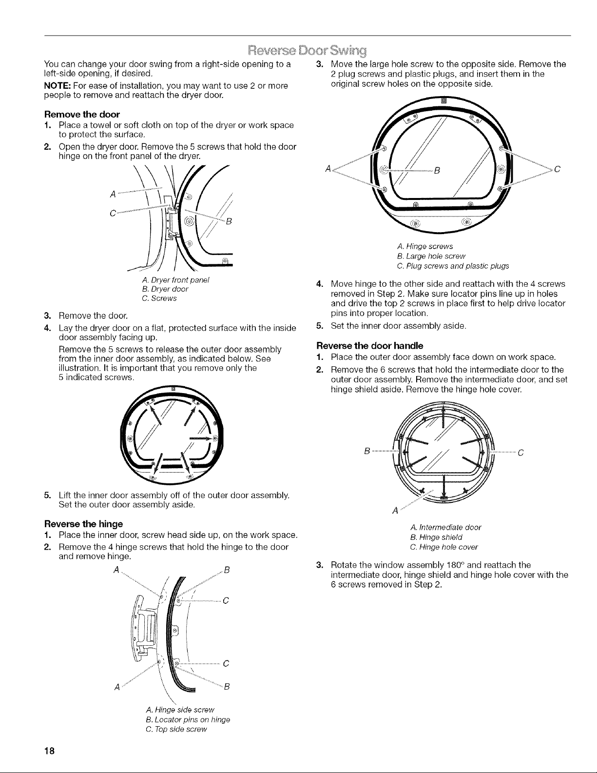
Remove the door
1. Place a towel or soft cloth on top of the dryer or work space
to protect the surface.
2. Open the dryer door. Remove the 5 screws that hold the door
hinge on the front panel of the dryer.
\
A. Hinge screws
B. Large hole screw
C. Plug screws and plastic plugs
A. Dryer front panel
B.Dryer door
C. Screws
3,
Remove the door.
4.
Lay the dryer door on a fiat, protected surface with the inside
door assembly facing up.
Remove the 5 screws to release the outer door assembly
from the inner door assembly, as indicated below. See
illustration. It is important that you remove only the
5 indicated screws.
4. Move hinge to the other side and reattach with the 4 screws
removed in Step 2. Make sure Iocator pins line up in holes
and drive the top 2 screws in place first to help drive Iocator
pins into proper location.
5. Set the inner door assembly aside.
Reverse the door handle
1. Place the outer door assembly face down on work space.
2. Remove the 6 screws that hold the intermediate door to the
outer door assembly. Remove the intermediate door, and set
hinge shield aside. Remove the hinge hole cover.
5. Lift the inner door assembly off of the outer door assembly.
Set the outer door assembly aside.
Reverse the hinge
1. Place the inner door, screw head side up, on the work space.
2. Remove the 4 hinge screws that hold the hinge to the door
and remove hinge.
A B
A. Hinge side screw
B. Locator pins on hinge
C. Top side screw
18
A. Intermediate door
B. Hinge shield
C. Hinge hole cover
3,
Rotate the window assembly 180° and reattach the
intermediate door, hinge shield and hinge hole cover with the
6 screws removed in Step 2.
 Loading...