


Kenmore Elite 11065064500, 11065066500, 11065062500 Owner’s Manual
L ! T
®
SENSOR SMART TMElectric Dryer
Secadora El_ctrica SENSOR SMART TM
iiiiii!Jiiiiiiiiiii!il
8571662 Sears Roebuck and Co., Hoffman Estates, IL 60179 U.S.A. www.sears.com
TABLE OF CONTENTS
PROTECTION AGREEMENTS ....................................................... 3
WARRANTY ..................................................................................... 3
DRYER SAFETY .............................................................................. 4
INSTALLATION INSTRUCTIONS .................................................. 5
Tools and Parts ............................................................................ 5
Location Requirements ............................................................... 5
Electrical Requirements ................................................................ 6
Electrical Connection ................................................................... 8
Venting Requirements ............................................................... 12
Plan Vent System ...................................................................... 13
Install Vent System .................................................................... 14
Install Leveling Legs .................................................................. 14
Level Dryer ................................................................................. 15
Connect Vent ............................................................................. 15
Complete Installation ................................................................. 15
DRYER USE ................................................................................. 16
Starting Your Dryer .................................................................... 16
Stopping Your Dryer .................................................................. 17
Pausing or Restarting ................................................................ 17
Loading ...................................................................................... 17
Drying and Cycle Tips ............................................................... 17
Dryer Status ............................................................................... 18
Cycles ........................................................................................ 18
Options ...................................................................................... 19
Modifiers .................................................................................... 19
Changing Cycles, Options and Modifiers ................................. 20
TUMBLE FREF MHeated Dryer Rack ....................................... 20
DRYER CARE ............................................................................... 21
Cleaning the Dryer Location ...................................................... 21
Cleaning the Lint Screen ........................................................... 21
Cleaning the Dryer Interior ........................................................ 21
Removing Accumulated Lint ..................................................... 22
Vacation and Moving Care ........................................................ 22
Changing the Drum Light .......................................................... 22
TROUBLESHOOTING .................................................................. 22
SERVICE NUMBERS ............................................... BACK COVER
PROTECTION AGREEMENTS
WARRANTY
Master Protection Agreements
Congratulations on making a smart purchase. Your new
Kenmore _product is designed and manufactured for years of
dependable operation. But like all products, it may require
preventive maintenance or repair from time to time. That's when
having a Master Protection Agreement can save you money and
aggravation.
Purchase a Master Protection Agreement now and protect
yourself from unexpected hassle and expense.
The Master Protection Agreement also helps extend the life of
your new product. Here's what's included in the Agreement:
v' Expert service by our 12,000 professional repair specialists
v' Unlimited service and no charge for parts and labor on all
covered repairs
v' "No-lemon" guarantee - replacement of your covered
product if four or more product failures occur within twelve
months
v' Product replacement if your covered product can't be fixed
v' Annual Preventive Maintenance Check at your request - no
extra charge
v' Fast help by phone - phone support from a Sears technician
on products requiring in-home repair, plus convenient repair
scheduling
v' Power surge protection against electrical damage due to
power fluctuations
v' Rental reimbursement if repair of your covered product takes
longer than promised
Once you purchase the Agreement, a simple phone call is all that
it takes for you to schedule service. You can call anytime day or
night, or schedule a service appointment online.
Sears has over 12,000 professional repair specialists, who have
access to over 4.5 million quality parts and accessories. That's
the kind of professionalism you can count on to help prolong the
life of your new purchase for years to come. Purchase your
Master Protection Agreement today!
Some limitations and exclusions apply. For prices and
additional information, call 1-800-827-6655.
Sears Installation Service
For Sears professional installation of home appliances, garage
door openers, water heaters, and other major home items, in the
U.S.A. call 1-800-4-MY-HOME ®.
FULL ONE-YEAR WARRANTY ON MECHANICAL AND
ELECTRICAL PARTS
For one year from the date of purchase, when this dryer is
installed and operated according to the instructions provided in
this Use and Care Guide, Sears will repair this dryer, free of
charge, if defective in materials or workmanship.
NOTE: Exhausting this dryer with a plastic vent can void this
warranty. See "Installation Instructions" for the complete exhaust
requirements for this dryer.
Limited Two-Year Warranty on SENSOR SMART TM
Electronic Control Board
For the second year from the date of purchase, Sears will replace
the electronic control board if defective in material or
workmanship. You will be charged for labor after the first year.
Warranty Restriction
If the dryer is subject to other than private family use, the above
warranty coverage is effective for only 90 days.
Warranty Service
Warranty service is available by contacting the nearest Sears
Service Center. This warranty applies only while the product is in
use in the United States.
This warranty gives you specific legal rights and you may also
have other rights which vary from state to state.
For Sears Warranty information or to contact a Sears Service
Center, please refer to the service numbers located on the back
page of this manual.
Sears, Roebuck and Co.
D/817WA, Noffman Estates, IL 60179
Product Record
In the space following, record your complete model number,
serial number, and purchase date. You can find this information
on the model and serial number label, located at the top inside
dryer door well.
Have this information available to help you quickly obtain
assistance or service when you contact Sears concerning your
appliance.
Model number 110.
Serial number
Purchase date
Save these instructions and your sales receipt for future
reference.
DRYER SAFETY
Your safety and the safety of others are very important.
We have provided many important safety messages in this manual and on your appliance. Always read and obey all safety
messages.
This is the safety alert symbol.
This symbol alerts you to potential hazards that can kill or hurt you and others.
All safety messages will follow the safety alert symbol and either the word "DANGER" or "WARNING."
These words mean:
You can be killed or seriously injured if you don't immediately
follow instructions.
You can be killed or seriously injured if you don't follow
instructions.
All safety messages will tell you what the potential hazard is, tell you how to reduce the chance of injury, and tell you what can
happen if the instructions are not followed.
iMPORTANT SAFETY iNSTRUCTiONS
WARNING: To reduce the risk of fire, electric shock, or injury to persons when using the dryer, follow basic precautions,
including the following:
m Read all instructions before using the dryer.
m Do not ptace items exposed to cooking oiIs in your dryer.
items contaminated with cooking oils may contribute to
a chemicat reaction that could cause a load to catch fire.
m Do not dry articles that have been previously cleaned in,
washed in, soaked in, or spotted with gasoline, dry=
cleaning solvents, other flammable, or explosive
substances as they give off vapors that could ignite or
explode.
m Do not allow children to play on or in the dryer. Close
supervision of children is necessary when the dryer is
used near children.
m Before the dryer is removed from service or discarded,
remove the door to the drying compartment.
m Do not reach into the dryer if the drum is moving.
m Do not install or store the dryer where it will be exposed
to the weather.
m Do not tamper with controls.
SAVE THESE INSTRUCTIONS
m Do not repair or replace any part of the dryer or attempt
any servicing unless specifically recommended in this
Use and Care Guide or in published user-repair
instructions that you understand and have the skills to
carry out.
m Do not use fabric softeners or products to eliminate static
unless recommended by the manufacturer of the fabric
softener or product.
m Do not use heat to dry articles containing foam rubber or
similariy textured rubber-like materials.
,, Clean lint screen before or after each load.
m Keep area around the exhaust opening and adjacent
surrounding areas free from the accumulation of lint, dust,
and dirt.
The interior of the dryer and exhaust vent should be
cleaned periodicaily by qualified service personnel.
See installation instructions for grounding requirements.
INSTALLATION INSTRUCTIONS
Gather the required tools and parts before starting installation.
Read and follow the safety instructions provided with any tools
listed here.
• Flat-blade screwdriver • #2 Phillips screwdriver
• Adjustable wrench that • Vent clamps
opens to 1" (2.5 cm) or
hex-head socket wrench • Caulking gun and
(for adjusting dryer feet) compound (for installing
• Level
• Wire stripper (direct wire installations)
installations)
Parts supplied:
Remove parts package from dryer drum. Check that all parts
were included.
4 levelinglegs
Parts needed:
Check local codes, check existing electrical supply and venting
and see "Electrical Requirements" and "Venting Requirements"
before purchasing parts.
Mobile home installations require metal exhaust system hardware
available for purchase from your local Sears store or Sears
Service Center. For further information, please call
1-8OO-4-MY-HOME ®(1-800-469-4663}.
new exhaust vent)
• Tin snips (new vent
Expmoeion Hazard
Keep flammable materials and vapors, such as
gaeomine, away from dryer.
Pmacedryer at Beast 18 inches (46 cm) above the floor
for a garage installation.
Failure to do so can resumt in death, expmoeion, or fire.
You will need
• A location that allows for proper exhaust installation. See
"Venting Requirements."
• A separate 30-amp circuit.
• A grounded electrical outlet located within 2 ft (61 cm) of
either side of the dryer. See "Electrical Requirements."
• A sturdy floor to support the total weight (dryer and load) of
200 Ibs (90.7 kg). The combined weight of a companion
appliance should also be considered.
A level floor with a maximum slope of 1" (2.5 cm) under entire
dryer. (If slope is greater than 1" [2.5 cm], install Extended
Dryer Feet Kit, Part No. 279810.) Clothes may not tumble
properly and models with automatic sensor cycles may not
operate correctly if dryer is not level.
Do not operate your dryer at temperatures below 45°F (7°C). At
lower temperatures, the dryer might not shut off at the end of an
automatic cycle. Drying times can be extended.
The dryer must not be installed or stored in an area where it will
be exposed to water and/or weather.
Check code requirements. Some codes limit, or do not permit,
installation of the dryer in garages, closets, mobile homes, or
sleeping quarters. Contact your local building inspector.
Installation Clearances
The location must be large enough to allow the dryer door to
open fully.
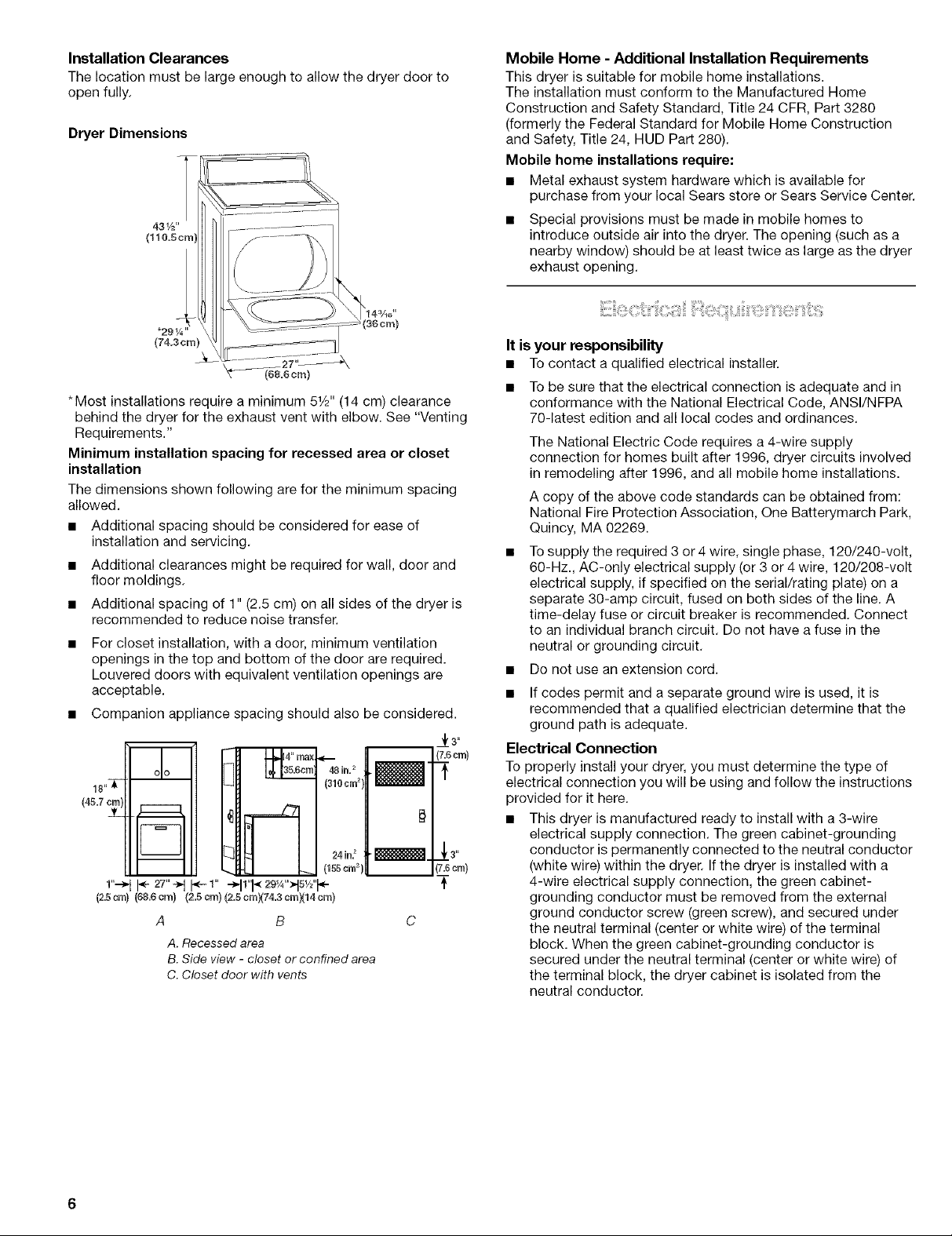
Dryer Dimensions
43!/2"
(110_5cm'
*291/4"
(74.3cm)
(68.6 cm)
*Most installations require a minimum 51/2'' (14 cm) clearance
behind the dryer for the exhaust vent with elbow. See "Venting
Requirements."
Minimum installation spacing for recessed area or closet
installation
The dimensions shown following are for the minimum spacing
allowed.
• Additional spacing should be considered for ease of
installation and servicing.
• Additional clearances might be required for wall, door and
floor moldings.
• Additional spacing of 1" (2.5 cm) on all sides of the dryer is
recommended to reduce noise transfer.
For closet installation, with a door, minimum ventilation
openings in the top and bottom of the door are required.
Louvered doors with equivalent ventilation openings are
acceptable.
• Companion appliance spacing should also be considered.
_.3"
(7.6crn}
(453
#
(7.6cm}
A B
A. Recessed area
B. Side view - closet or confined area
C. Closet door with vents
Mobile Home - Additional Installation Requirements
This dryer is suitable for mobile home installations.
The installation must conform to the Manufactured Home
Construction and Safety Standard, Title 24 CFR, Part 3280
(formerly the Federal Standard for Mobile Home Construction
and Safety, Title 24, HUD Part 280).
Mobile home installations require:
• Metal exhaust system hardware which is available for
purchase from your local Sears store or Sears Service Center.
Special provisions must be made in mobile homes to
introduce outside air into the dryer. The opening (such as a
nearby window) should be at least twice as large as the dryer
exhaust opening.
It is your responsibility
• Tocontact a qualified electrical installer.
• To be sure that the electrical connection is adequate and in
conformance with the National Electrical Code, ANSl/NFPA
70-latest edition and all local codes and ordinances.
The National Electric Code requires a 4-wire supply
connection for homes built after 1996, dryer circuits involved
in remodeling after 1996, and all mobile home installations.
A copy of the above code standards can be obtained from:
National Fire Protection Association, One Batterymarch Park,
Quincy, MA 02269.
Tosupply the required 3 or 4 wire, single phase, 120/240-volt,
60-Hz., AC-only electrical supply (or 3 or 4 wire, 120/208-volt
electrical supply, if specified on the serial/rating plate) on a
separate 30-amp circuit, fused on both sides of the line. A
time-delay fuse or circuit breaker is recommended. Connect
to an individual branch circuit. Do not have a fuse in the
neutral or grounding circuit.
• Do not use an extension cord.
• If codes permit and a separate ground wire is used, it is
recommended that a qualified electrician determine that the
ground path is adequate.
Electrical Connection
To properly install your dryer, you must determine the type of
electrical connection you will be using and follow the instructions
provided for it here.
• This dryer is manufactured ready to install with a 3-wire
electrical supply connection. The green cabinet-grounding
conductor is permanently connected to the neutral conductor
(white wire) within the dryer. If the dryer is installed with a
4-wire electrical supply connection, the green cabinet-
grounding conductor must be removed from the external
ground conductor screw (green screw), and secured under
the neutral terminal (center or white wire) of the terminal
block. When the green cabinet-grounding conductor is
secured under the neutral terminal (center or white wire) of
the terminal block, the dryer cabinet is isolated from the
neutral conductor.
Iflocalcodesdonotpermittheconnectionofacabinet
groundconductortotheneutralwire,see"Optional3-wire
connection"section.
Usea4-wireconductorcordwhenthedryerisinstalledina
mobilehomeoranareawherelocalcodesdonotpermit
groundingthroughtheneutral.
Ifusingapowersupplycord:
UseaULlistedpowersupplycordkitmarkedforusewith
clothesdryers.Thekitshouldcontain:
• AULlisted30-amppowersupplycord,rated
120/240-voltminimum.ThecordshouldbetypeSRDor
SRDTandbeatleast4ft(1.22m)long.Thewiresthat
connecttothedryermustendinringterminalsorspade
terminalswithupturnedends.
• AULlistedstrainrelief.
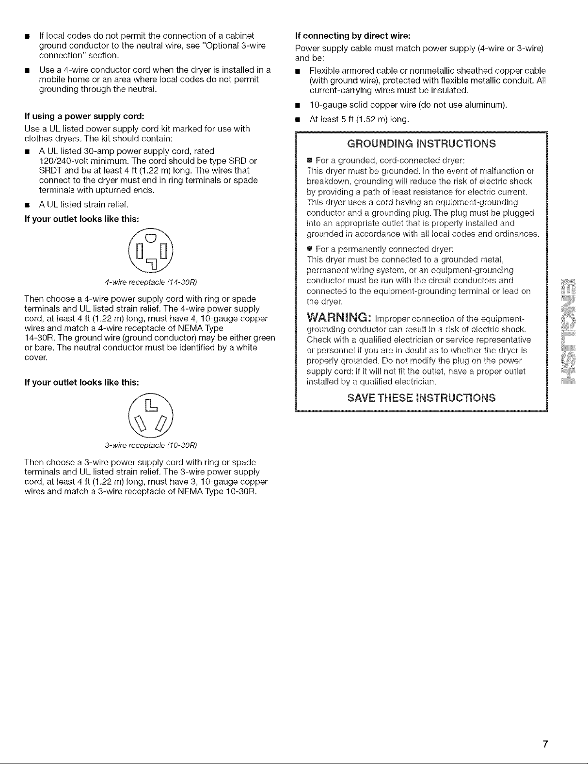
If your outlet looks like this:
4-wire receptacle (14-30R)
Then choose a 4-wire power supply cord with ring or spade
terminals and UL listed strain relief. The 4-wire power supply
cord, at least 4 ft (1.22 m) long, must have 4, 10-gauge copper
wires and match a 4-wire receptacle of NEMA Type
14-30R. The ground wire (ground conductor) may be either green
or bare. The neutral conductor must be identified by a white
cover.
If your outlet looks like this:
If connecting by direct wire:
Power supply cable must match power supply (4-wire or 3-wire)
and be:
• Flexible armored cable or nonmetallic sheathed copper cable
(with ground wire), protected with flexible metallic conduit. All
current-carrying wires must be insulated.
• 10-gauge solid copper wire (do not use aluminum).
• At least 5 ft (1.52 m) long.
GROUNDING iNSTRUCTiONS
m For a grounded, cord-connected dryer:
This dryer must be grounded. In the event of malfunction or
breakdown, grounding wil! reduce the risk of electric shock
by providing a path of least resistance for electric current.
This dryer uses a cord having an equipment-grounding
conductor and a grounding plug. The plug must be plugged
into an appropriate outlet that is properly installed and
grounded in accordance with all local codes and ordinances.
m For a permanently connected dryer:
This dryer must be connected to a grounded metal,
permanent wiring system, or an equipment-grounding
conductor must be run with the circuit conductors and
connected to the equipment-grounding terminal or lead on
the dryer.
WARNmNG: Improper connection of the equipment-
grounding conductor can result in a risk of electric shock.
Check with a qualified electrician or service representative
or personnel if you are in doubt as to whether the dryer is
properly grounded. Do not modify the plug on the power
supply cord: if it will not fit the outlet, have a proper outlet
installed by a qualified electrician.
SAVE THESE INSTRUCTIONS
3-wire receptacle (10-30R)
Then choose a 3-wire power supply cord with ring or spade
terminals and UL listed strain relief. The 3-wire power supply
cord, at least 4 ft (1.22 m) long, must have 3, 10-gauge copper
wires and match a 3-wire receptacle of NEMA Type 10-30R.
Power Supply Cord Direct Wire
Fire Hazard
Use a new UL misted30 amp power suppmy cord.
Use a UL misted strain reHefo
Disconnect power before making emectrical connections.
Connect neutram wire (white or center wire) to center
terminal (silver),
Ground wire (green or bare wire) must be connected to
green ground connector,
Connect remaining 2 supply wires to remaining
2 terminams (gored),
Securely tighten aHemectricat connections.
Failure to do so can resumt in death, fire, or
emectrical shock,
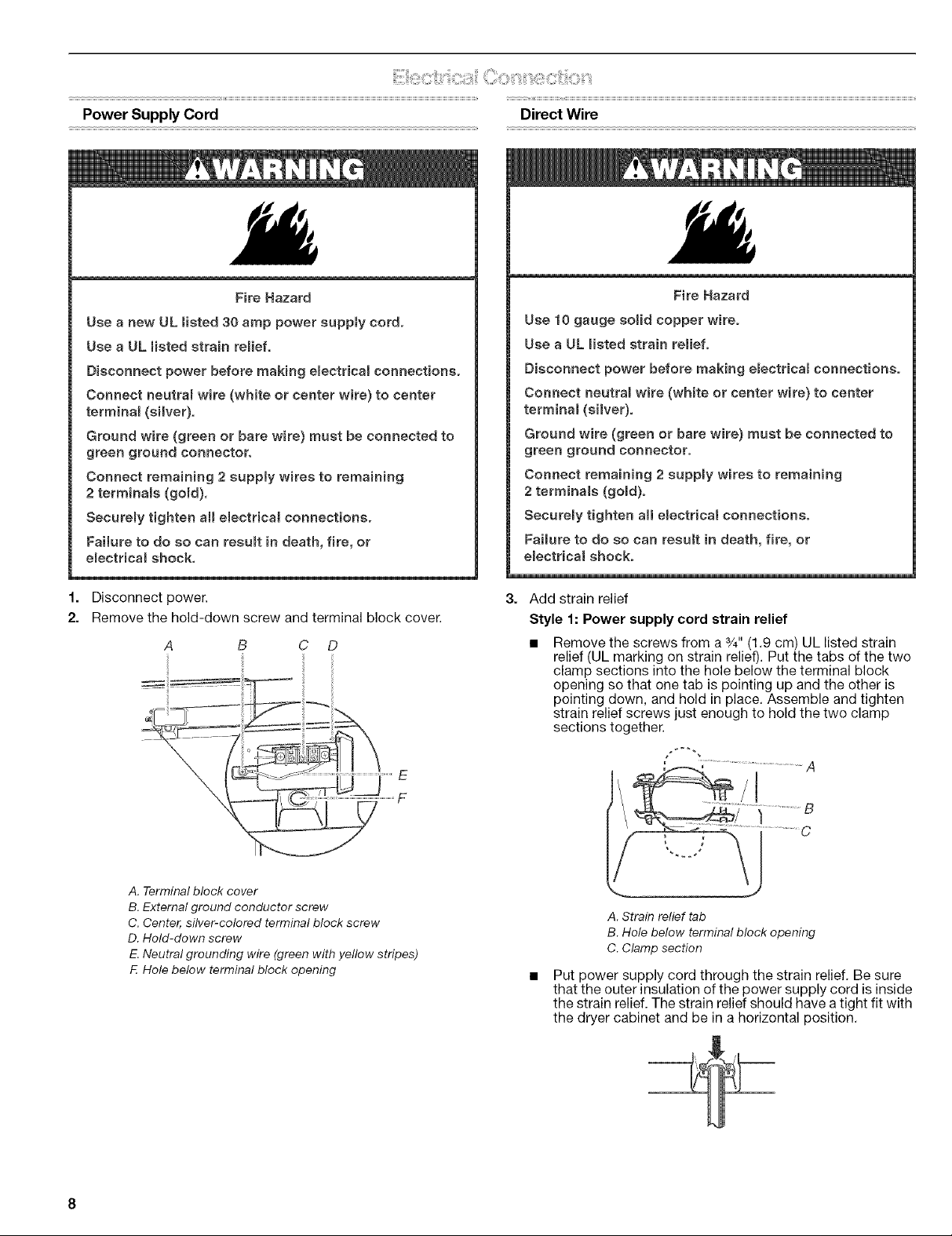
1. Disconnect power.
2. Remove the hold-down screw and terminal block cover.
B C D
Fire Hazard
Use 10 gauge somid copper wire.
Use a UL misted strain relief.
Disconnect power before making emectricamconnections.
Connect neutram wire (white or center wire) to center
terminal (silver).
Ground wire (green or bare wire) must be connected to
green ground connector.
Connect remaining 2 suppmy wires to remaining
2 terminals (gored).
SecureBy tighten aH emectrical connections.
Failure to do so can result in death, fire, or
electrical shock.
3. Add strain relief
Style 1: Power supply cord strain relief
• Remove the screws from a 3/4"(1.9 cm) UL listed strain
relief (UL marking on strain relief). Put the tabs of the two
clamp sections into the hole below the terminal block
opening so that one tab is pointing up and the other is
pointing down, and hold in place. Assemble and tighten
strain relief screws just enough to hold the two clamp
sections together.
A. Terminal block cover
B. External ground conductor screw
C. Center, silver-colored terminal block screw
D. Hold-down screw
E. Neutral grounding wire (green with yellow stripes)
F. Hole below terminal block opening
E
F
... J
A. Strain relief tab
B. Hole below terminal block opening
C. Clamp section
Put power supply cord through the strain relief. Be sure
that the outer insulation of the power supply cord is inside
the strain relief. The strain relief should have a tight fit with
the dryer cabinet and be in a horizontal position.
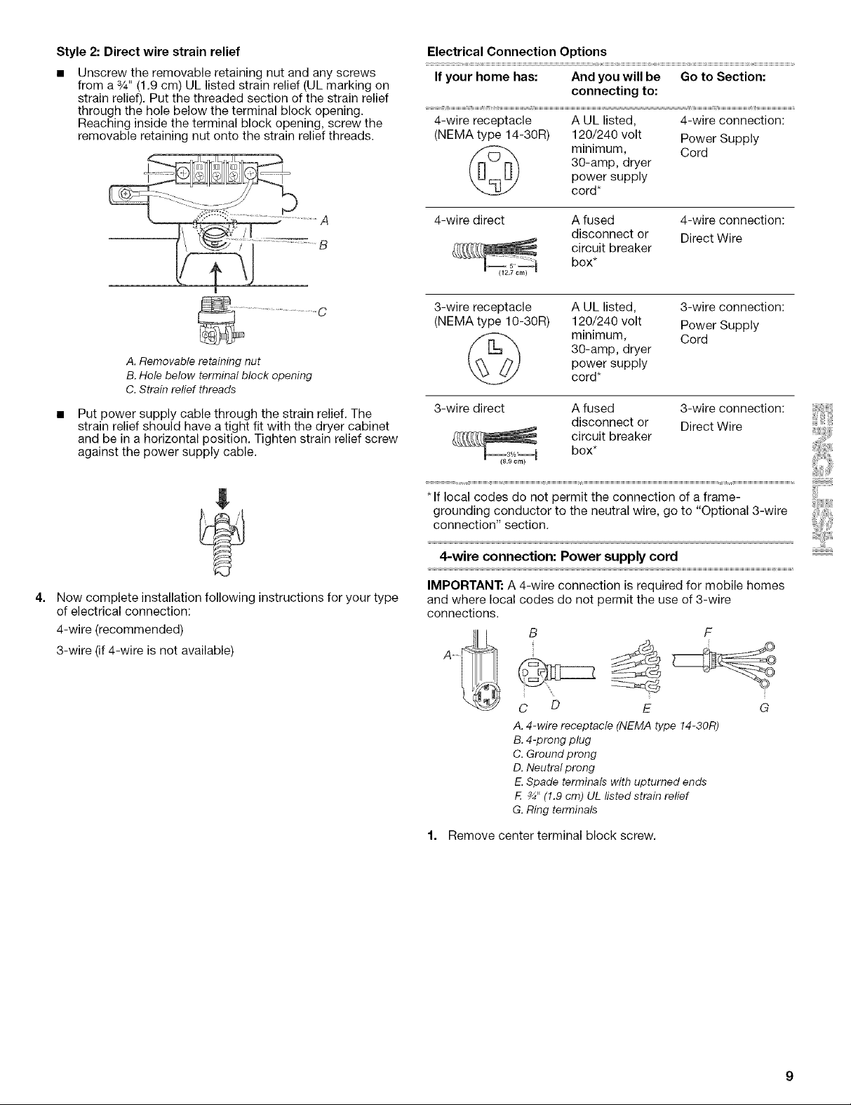
Style 2: Direct wire strain relief
Unscrew the removable retaining nut and any screws
from a %" (1.9 cm) UL listed strain relief (UL marking on
strain relief). Put the threaded section of the strain relief
through the hole below the terminal block opening.
Reaching inside the terminal block opening, screw the
removable retaining nut onto the strain relief threads.
A. Removable retaining nut
B. Hole below terminal block opening
C. Strain relief threads
Put power supply cable through the strain relief. The
strain relief should have a tight fit with the dryer cabinet
and be in a horizontal position. Tighten strain relief screw
against the power supply cable.
Electrical Connection Options
If your home has: And you will be Go to Section:
connecting to:
4-wire receptacle A UL listed, 4-wire connection:
(NEMA type 14-30R) 120/240 volt Power Supply
30-amp, dryer
power supply
minimum, Cord
cord*
4-wire direct A fused 4-wire connection:
disconnect or Direct Wire
circuit breaker
box*
3-wire receptacle A UL listed, 3-wire connection:
(NEMA type 10-30R) 120/240 volt Power Supply
30-amp, dryer
power supply
minimum, Cord
cord*
3-wire direct A fused 3-wire connection:
disconnect or Direct Wire
circuit breaker
box*
Now complete installation following instructions for your type
of electrical connection:
4-wire (recommended)
3-wire (if 4-wire is not available)
* If local codes do not permit the connection of a frame-
grounding conductor to the neutral wire, go to "Optional 3-wire
connection" section.
4-wire connection: Power supply cord
IMPORTANT: A 4-wire connection is required for mobile homes
and where local codes do not permit the use of 3-wire
connections.
B
F
C D E G
A.4-wire receptacle (NEMA type 14-30R)
B.4-prong plug
C.Ground prong
D.Neutral prong
E.Spade terminals withupturned ends
F. _" (1.9cm) UL listed strain relief
G.Ring terminals
1. Remove center terminal block screw.
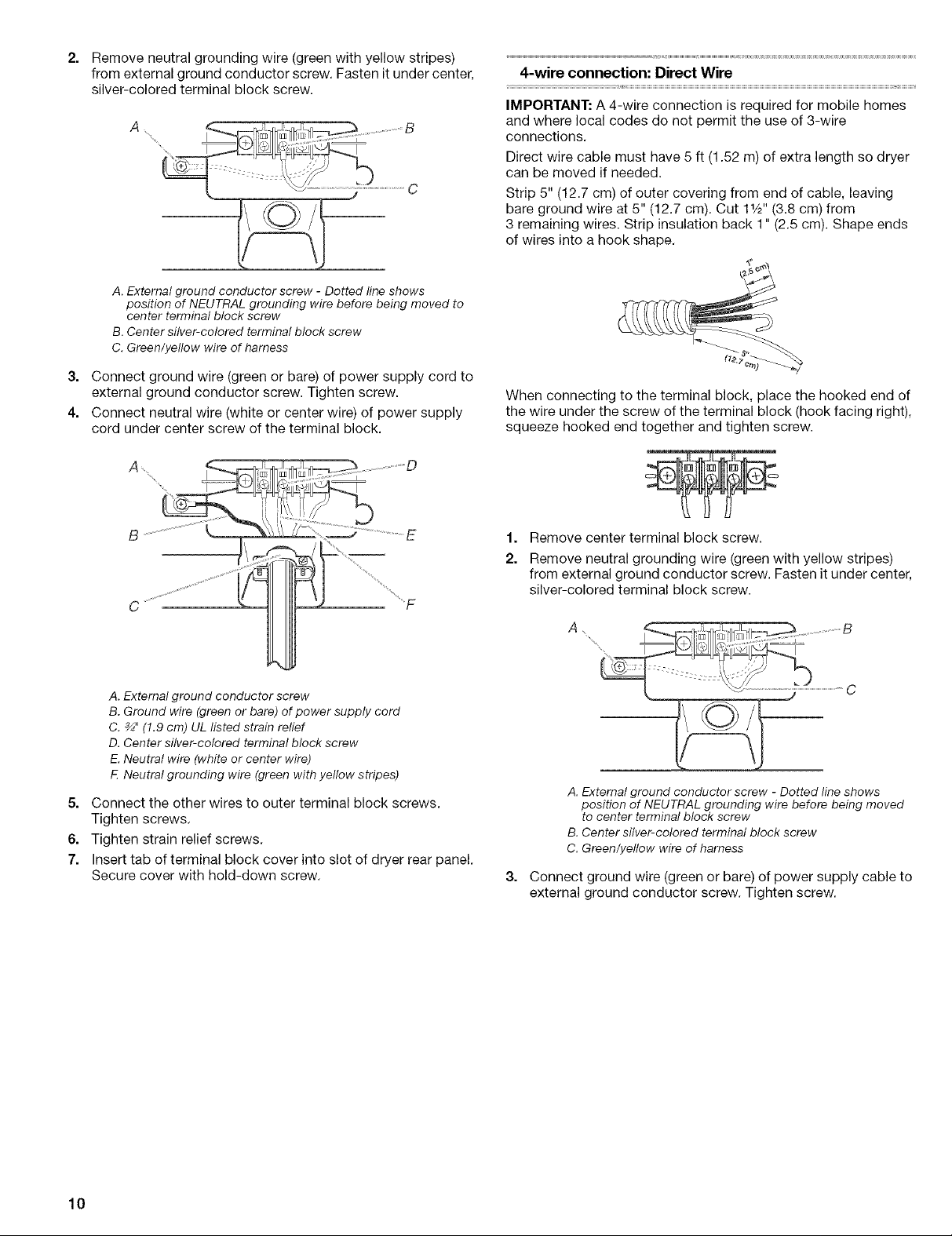
2=
Remove neutral grounding wire (green with yellow stripes)
from external ground conductor screw. Fasten it under center,
silver-colored terminal block screw.
A
A. External ground conductor screw - Dotted line shows
position of NEUTRAL grounding wire before being moved to
center terminal block screw
B. Center silver-colored terminal block screw
C. Green/yeilow wire of harness
3. Connect ground wire (green or bare) of power supply cord to
external ground conductor screw. Tighten screw.
4. Connect neutral wire (white or center wire) of power supply
cord under center screw of the terminal block.
4-wire connection: Direct Wire
IMPORTANT: A 4-wire connection is required for mobile homes
and where local codes do not permit the use of 3-wire
connections.
Direct wire cable must have 5 ft (1.52 m) of extra length so dryer
can be moved if needed.
Strip 5" (12.7 cm) of outer covering from end of cable, leaving
bare ground wire at 5" (12.7 cm). Cut 11/2'' (3.8 cm) from
3 remaining wires. Strip insulation back 1" (2.5 cm). Shape ends
of wires into a hook shape.
When connecting to the terminal block, place the hooked end of
the wire under the screw of the terminal block (hook facing right),
squeeze hooked end together and tighten screw.
A. External ground conductor screw
B. Ground wire (green or bare) of power supply cord
C. _" (1.9 cm) UL listed strain relief
D. Center silver-colored terminal block screw
E. Neutral wire (white or center wire)
F. Neutral grounding wire (green with yellow stripes)
5. Connect the other wires to outer terminal block screws.
Tighten screws.
6. Tighten strain relief screws.
7. Insert tab of terminal block cover into slot of dryer rear panel.
Secure cover with hold-down screw.
1=
Remove center terminal block screw.
2.
Remove neutral grounding wire (green with yellow stripes)
from external ground conductor screw. Fasten it under center,
silver-colored terminal block screw.
A. External ground conductor screw - Dotted line shows
position of NEUTRAL grounding wire before being moved
to center terminal block screw
B. Center silver-colored terminal block screw
C. Green/yellow wire of harness
3=
Connect ground wire (green or bare) of power supply cable to
external ground conductor screw. Tighten screw.
10
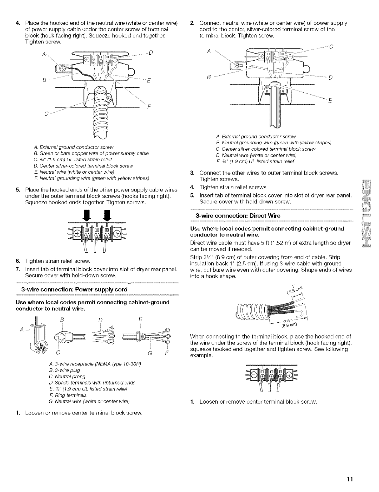
Place the hooked end of the neutral wire (white or center wire)
of power supply cable under the center screw of terminal
block (hook facing right), Squeeze hooked end together.
Tighten screw.
A. External ground conductor screw
B. Green or bare copper wire of power supply cable
C. _" (1.9 cm) UL ilsted strain relief
D. Center silver-colored terminal block screw
E Neutral wire (white or center wire)
F Neutral grounding wire (green with yellow stripes)
Place the hooked ends of the other power supply cable wires
under the outer terminal block screws (hooks facing right).
Squeeze hooked ends together. Tighten screws.
2. Connect neutral wire (white or center wire) of power supply
cord to the center, silver-colored terminal screw of the
terminal block. Tighten screw.
C
A .................. _;
...........................................\\,/'
A.External ground conductor screw
B. Neutral grounding wire (greenwith yellow stripes)
C. Centersilver-colored terminal block screw
D.Neutral wire (white or center wire)
E._" (1.9 cm) UL listed strain relief
3. Connect the other wires to outer terminal block screws.
Tighten screws.
4. Tighten strain relief screws.
5. Insert tab of terminal block cover into slot of dryer rear panel.
Secure cover with hold-down screw.
!! !!
6. Tighten strain relief screw.
7. Insert tab of terminal block cover into slot of dryer rear panel.
Secure cover with hold-down screw.
3-wire connection: Power supply cord
Use where local codes permit connecting cabinet-ground
conductor to neutral wire.
=_
A
G F
A. 3-wire receptacle (NEMA type 10-30R)
B, 3-wire plug
C. Neutral prong
D. Spade terminals with upturned ends
E. _" (1.9 cm) UL listed strain relief
E Ring terminals
G. Neutral wire (white or center wire)
1. Loosen or remove center terminal block screw.
3-wire connection: Direct Wire
Use where local codes permit connecting cabinet-ground
conductor to neutral wire.
Direct wire cable must have 5 ft (1.52 m) of extra length so dryer
can be moved if needed.
Strip 31/2'' (8.9 cm) of outer covering from end of cable, Strip
insulation back 1" (2.5 cm). If using 3-wire cable with ground
wire, cut bare wire even with outer covering. Shape ends of wires
into a hook shape,
When connecting to the terminal block, place the hooked end of
the wire under the screw of the terminal block (hook facing right),
squeeze hooked end together and tighten screw. See following
example.
1. Loosen or remove center terminal block screw.
11
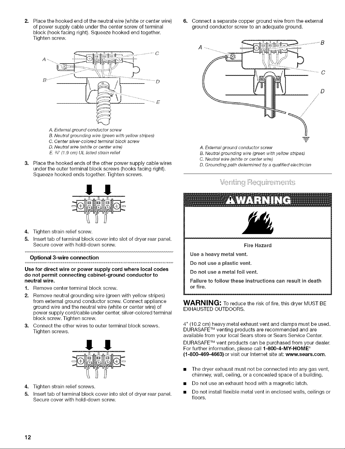
2. 6. Connect a separate copper ground wire from the external
Place the hooked end of the neutral wire (white or center wire)
of power supply cable under the center screw of terminal
block (hook facing right). Squeeze hooked end together.
Tighten screw.
C
A. External ground conductor screw
B. Neutral grounding wire (green with yellow stripes)
C. Center silver-colored terminal block screw
D. Neutral wire (white or center wire)
E. _" (!.9 cm) UL listed strain relief
3. Place the hooked ends of the other power supply cable wires
under the outer terminal block screws (hooks facing right).
Squeeze hooked ends together. Tighten screws.
ground conductor screw to an adequate ground.
A. External ground conductor screw
B. Neutral grounding wire (green with yellow stripes)
C. Neutral wire (white or center wire)
D. Grounding path determined by a qualified electrician
D
!! !!
4. Tighten strain relief screw.
5. Insert tab of terminal block cover into slot of dryer rear panel.
Secure cover with hold-down screw.
Optional 3-wire connection
Use for direct wire or power supply cord where local codes
do not permit connecting cabinet-ground conductor to
neutral wire.
1. Remove center terminal block screw.
2. Remove neutral grounding wire (green with yellow stripes)
from external ground conductor screw. Connect appliance
ground wire and the neutral wire (white or center wire) of
power supply cord/cable under center, silver-colored terminal
block screw. Tighten screw.
3. Connect the other wires to outer terminal block screws.
Tighten screws.
!! !!
Fire Hazard
Use a heavy meta_ vent,
Do not use a p_astic vent.
Do not use a meta_ foil vent.
Failure to follow these instructions can result in death
or fire.
WARNING; To reduce the risk of fire, this dryer MUST BE
EXHAUSTED OUTDOORS.
4" (10.2 cm) heavy metal exhaust vent and clamps must be used.
DURASAFE TM venting products are recommended and are
available from your local Sears store or Sears Service Center.
DURASAFF Mvent products can be purchased from your dealer.
For further information, please call f-800-4-MY-HOME ®
(f-800-469-4663} or visit our Internet site at: www.sears.com.
4. Tighten strain relief screws.
5. Insert tab of terminal block cover into slot of dryer rear panel.
Secure cover with hold-down screw.
12
• The dryer exhaust must not be connected into any gas vent,
chimney, wall, ceiling, or a concealed space of a building.
• Do not use an exhaust hood with a magnetic latch.
• Do not install flexible metal vent in enclosed walls, ceilings or
floors.
• Use clamps to seal all joints. Exhaust vent must not be
connected or secured with screws or other fastening devices
that extend into the interior of the duct. Do not use duct tape.
IMPORTANT: Observe all governing codes and ordinances.
Improper venting can cause moisture and mintto collect
indoors, which may result in:
[] Moisture damage to woodwork, furniture, paint,
wallpaper, carpets, etc=
[] Housecleaning problems and health problems.
Use a heavy metal vent. Do not use plastic or metal foil vent.
Rigid metal vent is recommended to prevent crushing and
kinking.
Flexible metal vent must be fully extended and supported when
the dryer is in its final position. Remove excess flexible metal vent
to avoid sagging and kinking that may result in reduced airflow
and poor performance.
An exhaust hood should cap the vent to prevent rodents and
insects from entering the home.
Exhaust hood must be at least 12" (30.5 cm) from the ground or
any object that may be in the path of the exhaust (such as
flowers, rocks or bushes, etc.).
If using an existing vent system, clean lint from the entire length
of the system and make sure exhaust hood is not plugged with
lint. Replace any plastic or metal foil vent with rigid metal or
flexible metal vent.
Fire Hazard
Cover unused exhaust holes with one of the following
kits:
279818 (white)
279819 (atmond)
279915 (graphite)
279925 (biscuit)
Contact your local dealer.
Failure to follow these instructions can result in death,
fire, electrical shock, or serious injury.
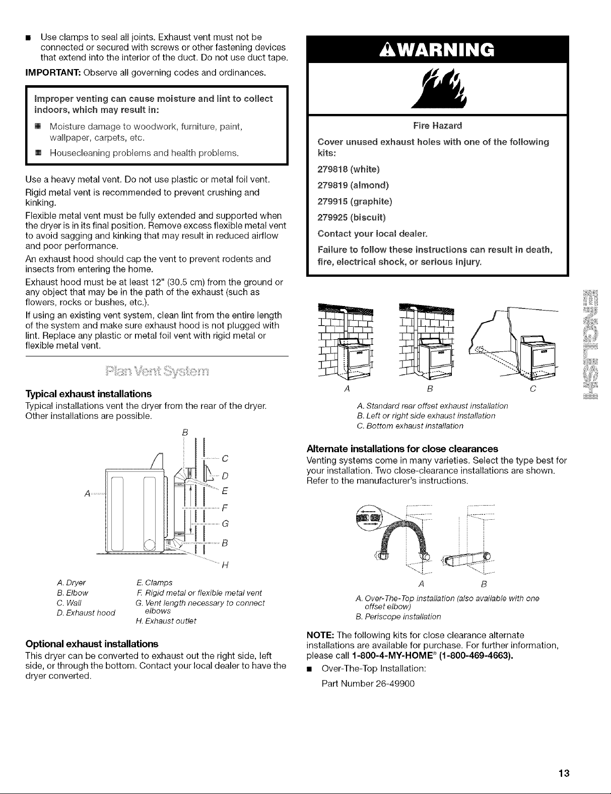
Typical exhaust installations
Typical installations vent the dryer from the rear of the dryer.
Other installations are possible.
/1
..... C
A ............
.............................................................F
[
A. Dryer E. Clamps
B. Elbow F. Rigid metal or flexible metal vent
C. Wall G. Vent length necessary to connect
D. Exhaust hood elbows
H. Exhaust outlet
Optional exhaust installations
This dryer can be converted to exhaust out the right side, left
side, or through the bottom. Contact your local dealer to have the
dryer converted.
A B C
A. Standard rear offset exhaust installation
B. Left or right side exhaust installation
C. Bottom exhaust installation
Alternate installations for close clearances
Venting systems come in many varieties. Select the type best for
your installation. Two close-clearance installations are shown.
Refer to the manufacturer's instructions.
.....i..... "--4......
A B
A. Over-The-Topinstallation (also available with one
offset elbow)
B.Periscope installation
NOTE: The following kits for close clearance alternate
installations are available for purchase. For further information,
please call 1-800-4-MY-HOME ® (1-800-469-4663}.
• Over-The-Top Installation:
Part Number 26-49900
13
• Periscope Installation (For use with dryer vent to wall vent See the exhaust vent length chart that matches your hood
mismatch): type for the maximum vent lengths you can use.
Part Number 26-49901 - Less than 5" (12.7 cm) mismatch
Part Number 26-49908 - 5" (12.7 cm) to 18" (45.72 cm)
mismatch
Part Number 26-49904 - 18" (45.72 cm) to 29" (73.66 cm)
mismatch
Part Number 26-49905 - 29" (73.66 cm) to 50" (127 cm)
mismatch
Special provisions for mobile home installations
The exhaust vent must be securely fastened to a noncombustible
portion of the mobile home structure and must not terminate
beneath the mobile home. Terminate the exhaust vent outside.
Exhaust systems longer than specified will:
• Shorten the life of the dryer.
• Reduce performance, resulting in longer drying times and
increased energy usage.
3=
Determine the number of elbows you will need.
NOTE: Do not use vent runs longer than specified in the Vent
Length Chart.
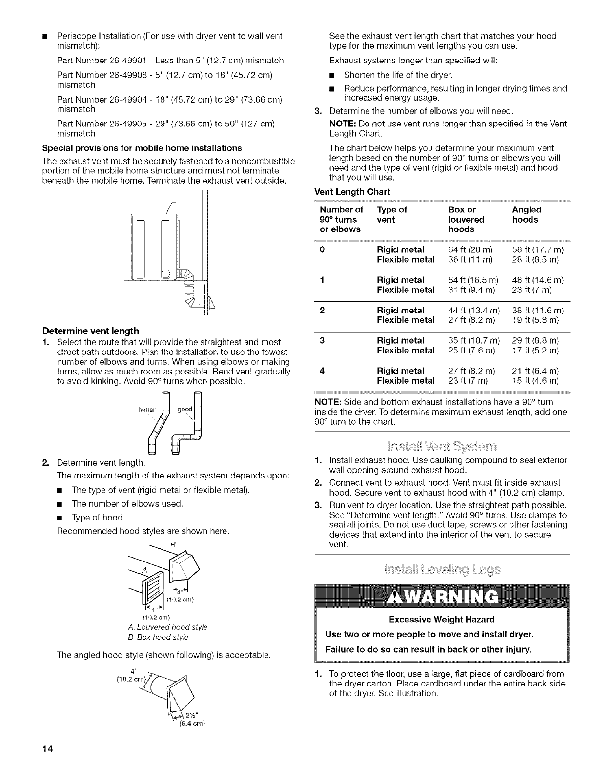
The chart below helps you determine your maximum vent
length based on the number of 90° turns or elbows you will
need and the type of vent (rigid or flexible metal) and hood
that you will use.
Vent Length Chart
S
Number of Type of Box or Angled
90° turns vent Iouvered hoods
or elbows hoods
0 Rigid metal 64 ft (20 m) 58 ft (17.7 m)
Flexible metal 36 ft (11 m) 28 ft (8.5 m)
1 Rigid metal 54 ft (16.5 m) 48 ft (14.6 m)
Flexible metal 31 ft (9.4 m) 23 ft (7 m)
2 Rigid metal 44 ft (13.4 m) 38 ft (11.6 m)
Flexible metal 27 ft (8.2 m) 19 ft (5.8 m)
Determine vent length
1.
Select the route that will provide the straightest and most
direct path outdoors. Plan the installation to use the fewest
3 Rigid metal 35 ft (10.7 m) 29 ft (8.8 m)
Flexible metal 25 ft (7.6 m) 17 ft (5.2 m)
number of elbows and turns. When using elbows or making
turns, allow as much room as possible. Bend vent gradually
to avoid kinking. Avoid 90° turns when possible.
4 Rigid metal 27 ft (8.2 m) 21 ft (6.4 m)
Flexible metal 23 ft (7 m) 15 ft (4.6 m)
i
2.
Determine vent length.
The maximum length of the exhaust system depends upon:
• The type of vent (rigid metal or flexible metal).
• The number of elbows used.
• Type of hood.
Recommended hood styles are shown here.
B
A.Louvered hood style
B.Box hood style
The angled hood style (shown following) is acceptable.
4"
NOTE: Side and bottom exhaust installations have a 90° turn
inside the dryer. To determine maximum exhaust length, add one
90° turn to the chart.
1. Install exhaust hood. Use caulking compound to seal exterior
wall opening around exhaust hood.
2. Connect vent to exhaust hood. Vent must fit inside exhaust
hood. Secure vent to exhaust hood with 4" (10.2 cm) clamp.
3. Run vent to dryer location. Use the straightest path possible.
See "Determine vent length." Avoid 90° turns. Use clamps to
seal all joints. Do not use duct tape, screws or other fastening
devices that extend into the interior of the vent to secure
vent.
Excessive Weight Hazard
Use two or more people to move and install dryer.
Failure to do so can result in back or other injury.
1. To protect the floor, use a large, flat piece of cardboard from
the dryer carton. Place cardboard under the entire back side
of the dryer. See illustration.
14
(6.4era)
2. Firmly grasp the body of the dryer (not the top or console
panel). Gently lay the dryer on the cardboard.
Examine the leveling legs. Find the diamond marking.
4. Screw the legs into the leg holes by hand. Use a wrench to
finish turning the legs until the diamond marking is no longer
visible.
5. Place a carton corner post under each of the 2 dryer back
corners. Stand the dryer up. Slide the dryer on the corner
posts until it is close to its final location. Leave enough room
to connect the exhaust vent.
6. Once connection is made and dryer is in final location,
remove corner posts and cardboard.
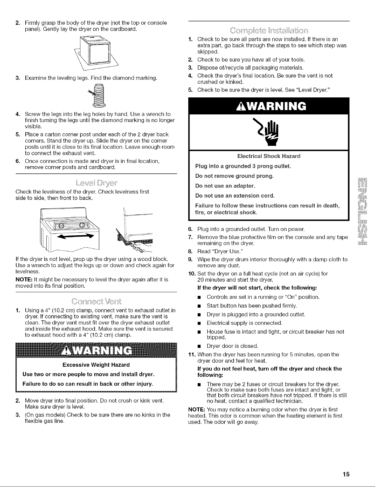
Check the levelness of the dryer. Check levelness first
side to side, then front to back.
1. Check to be sure all parts are now installed. If there is an
extra part, go back through the steps to see which step was
skipped.
2. Check to be sure you have all of your tools.
3. Dispose of/recycle all packaging materials.
4. Check the dryer's final location. Be sure the vent is not
crushed or kinked.
5. Check to be sure the dryer is level. See "Level Dryer."
Electricam Shock Hazard
Pmug into a grounded 3 prong outlet.
Do not remove ground prong.
Do not use an adapter,
Do not use an extension cord,
Faimure to follow these instructions can resumt in death,
fire, or eiectricam shock,
If the dryer is not level, prop up the dryer using a wood block.
Use a wrench to adjust the legs up or down and check again for
levelness.
NOTE: It might be necessary to level the dryer again after it is
moved into its final position.
Using a 4" (10.2 cm) clamp, connect vent to exhaust outlet in
dryer. If connecting to existing vent, make sure the vent is
clean. The dryer vent must fit over the dryer exhaust outlet
and inside the exhaust hood. Make sure the vent is secured
to exhaust hood with a 4" (10.2 cm) clamp.
2. Move dryer into final position. Do not crush or kink vent.
Make sure dryer is level.
3. (On gas models) Check to be sure there are no kinks in the
flexible gas line.
6. Plug into a grounded outlet. Turn on power.
7. Remove the blue protective film on the console and any tape
remaining on the dryer.
8. Read "Dryer Use."
9. Wipe the dryer drum interior thoroughly with a damp cloth to
remove any dust.
fg. Set the dryer on a full heat cycle (not an air cycle) for
20 minutes and start the dryer.
If the dryer will not start, check the following:
• Controls are set in a running or "On" position.
• Start button has been pushed firmly.
• Dryer is plugged into a grounded outlet.
• Electrical supply is connected.
• House fuse is intact and tight, or circuit breaker has not
tripped.
• Dryer door is closed.
11. When the dryer has been running for 5 minutes, open the
dryer door and feel for heat.
If you do not feel heat, turn off the dryer and check the
following:
• There may be 2 fuses or circuit breakers for the dryer.
Check to make sure both fuses are intact and tight, or
that both circuit breakers have not tripped. If there is still
no heat, contact a qualified technician.
NOTE: You may notice a burning odor when the dryer is first
heated. This odor is common when the heating element is first
used. The odor will go away.
15
 Loading...