


Kenmore Elite 23351282710, 23351283710, 23351289710, 23351292710, 23351299710 Owner’s Manual
Use & Care / Installation Manual Manual de Uso y Cuidado / Instalación
English / Español
Models/Modelos 51282*, 51283*, 51289*
51292*, 51299*, 51353*
Kenmore®
Range Hood
Campana de cocina
* = color number, número de color
P/N 99045662-009A
Sears Brands Management Corporation,
Ho man Estates, IL 60179 USA
www.kenmore.com
www.sears.com
TM

READ AND SAVE THESE INSTRUCTIONS
TABLE OF CONTENTS |
|
SECTION ............................................................. |
PAGE |
Warranty............................................................................... |
2 |
Safety Instructions ............................................................... |
3 |
Operation.............................................................................. |
4 |
Cleaning ................................................................................ |
4 |
Parts Included With Hood ................................................. |
5 |
Parts Not Included With Hood ......................................... |
5 |
Tools Needed ....................................................................... |
5 |
Equivalent Duct Length Chart ........................................... |
6 |
Install Ductwork ................................................................. |
7 |
Prepare The Hood ......................................................... |
7-9 |
Prepare The Hood Location ....................................... |
10-13 |
EZ1 One-Person Installation ............................... |
10-11 |
Install The Hood (EZ-1 Brackets) ............................ |
12 |
Standard Installation (without EZ1 Brackets) ....... |
13 |
Install The Hood (Standard Installation) ............... |
13 |
Connect The Wiring .......................................................... |
14 |
Install The Light Bulbs........................................................ |
15 |
Install The Filters ............................................................... |
15 |
Service Parts ...................................................................... |
16 |
Master Protection Agreements ....................................... |
17 |
KENMORE LIMITED WARRANTY
When this appliance is installed, operated and maintained according to all supplied instructions, the following warranty coverage applies. To arrange for warranty service, call 1-800-4-MY-HOME® (1-800-469-4663).
•For one year from the date of purchase, any part of this product that fails due to a defect in material or workmanship will receive free repair or replacement if repair proves impossible. The length of this coverage does not apply to the finish of any painted or bright metal part.
•For thirty days date of purchase, any painted or bright metal part of this product will be replaced free of charge if its finish is defective in material or workmanship.
All warranty coverage is void if this product is ever used for other than private household purposes.
This warranty covers only defects in material and workmanship, and will NOT pay for:
1.Consumable parts that can wear out from normal use, including but not limited to filters, belts, light bulbs, and bags.
2.A service technician to instruct the user in correct product installation, operation or maintenance.
3.A service technician to clean or maintain this product.
4.Damage to or failure of this product if it is not installed, operated or maintained according to the all instructions supplied with the product.
5.Damage to or failure of this product resulting from accident, abuse, misuse or use for other than its intended purpose.
6.Damage to or failure of this product caused by the use of detergents, cleaners, chemicals or utensils other than those recommended in all instructions supplied with the product.
7.Damage to or failure of parts or systems resulting from unauthorized modifications made to this product.
Disclaimer of implied warranties; limitation of remedies
Customer’s sole and exclusive remedy under this limited warranty shall be product repair as provided herein. Implied warranties, including warranties of merchantability or fitness for a particular purpose, are limited to one year or the shortest period allowed by law. Sears shall not be liable for incidental or consequential damages. Some states and provinces do not allow the exclusion
or limitation of incidental or consequential damages, or limitation on the duration ofimplied warranties of merchantability or fitness, so these exclusions or limitations may not apply to you.
This warranty gives you specific legal rights, and you may also have other rights which vary from state to state.
Sears Brands Management Corporation,
Ho man Estates, IL 60179
2
SAFETY INSTRUCTIONS
 !
!  INTENDED FOR DOMESTIC COOKING ONLY.
  !
! 
WARNING
TO REDUCE THE RISK OF FIRE, ELECTRIC SHOCK, OR INJURY TO PERSONS, OBSERVE THE FOLLOWING:
1.Use this unit only in the manner intended by the manufacturer. If you have questions, contact the manufacturer at the address listed in the warranty.
2.Before servicing or cleaning unit, switch power o at service panel and lock the service disconnecting means to prevent power from being switched on accidentally. When the service disconnecting means cannot be locked, securely fasten a prominent warning device, such as a tag, to the service panel.
3.Installation work and electrical wiring must be done by a qualified person(s) in accordance with all applicable codes and standards, including fire-rated codes and standards.
4.Su cient air is needed for proper combustion and exhausting of gases through the flue (chimney) of fuel burning equipment to prevent backdrafting. Follow the heating equipment manufacturer’s guideline and safety standards such as those published by the National Fire Protection Association (NFPA), and the American Society for Heating, Refrigeration and Air Conditioning Engineers (ASHRAE), and the local code authorities.
5.When cutting or drilling into wall or ceiling, do not damage electrical wiring and other hidden utilities.
6.To reduce the risk of fire or electric shock, do not use this range hood with an additional speed control device.
7.Ducted fans must always be vented to the outdoors.
8.To reduce the risk of fire, use only metal ductwork.
9.This unit must be grounded.
TO REDUCE THE RISK OF A RANGE TOP GREASE FIRE:
1.Never leave surface units unattended at high settings. Boilovers cause smoking and greasy spillovers that may ignite. Heat oils slowly on low or medium settings.
2.Always turn hood ON when cooking at high heat or when cooking flaming foods.
3.Clean ventilating fans frequently. Grease should not be allowed to accumulate on fan or filter.
4.Use proper pan size. Always use cookware appropriate for the size of the surface element.
TO REDUCE THE RISK OF INJURY TO PERSONS IN THE EVENT OF A RANGE TOP GREASE FIRE, OBSERVE THE FOLLOWING:*
1.SMOTHER FLAMES with a close-fitting lid, cookie sheet, or metal tray, then turn o the burner. BE CAREFUL TO PREVENT BURNS. If the flames do not go out immediately, EVACUATE AND CALL THE FIRE DEPARTMENT.
2.NEVER PICK UP A FLAMING PAN - You may be burned.
3.DO NOT USE WATER, including wet dishcloths or towels - a violent steam explosion will result.
4.Use an extinguisher ONLY if:
A.You know you have a Class ABC extinguisher and you already know how to operate it.
B.The fire is small and contained in the area where it started.
C.The fire department is being called.
D.You can fight the fire with your back to an exit. * Based on “Kitchen Fire safety Tips” published by NFPA.
CAUTION  !
! 
1.For general ventilating use only. Do not use to exhaust hazardous or explosive materials and vapors.
2.To avoid motor bearing damage and noisy and/ or unbalanced impellers, keep drywall spray, construction dust, etc. o power unit.
3.For best capture of cooking impurities, your range hood should be mounted so that the top of the hood is 18-24” above the cooking surface.
4.Use only with range hood cord-connection kits that have been investigated and found acceptable for use with this model range hood.
5.Please read specification label on product for further information and requirements.
NOTE |
If hood is to be installed Non-Ducted:
Purchase non-ducted filters and attach them to the aluminum mesh filters.
“Non-ducted Filters” available by calling Sears at 1-800-4-MY-HOME®
3
Warranty
Safety
Operation
Cleaning
Installation
Parts Service
OPERATION |
|
CLEANING |
|
|
|
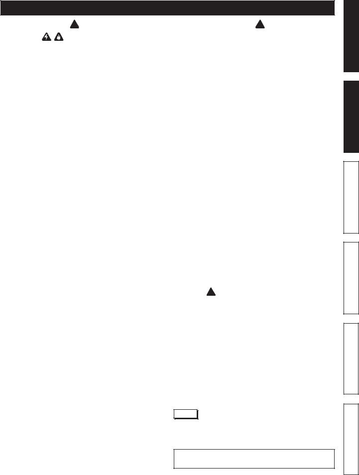
BLOWER SPEED LEVEL |
|
|
|
LIGHT INTENSITY |
||||||||||
PUSH BUTTONS |
LEVELS PUSH BUTTON |
|||||||||||||
|
|
|
|
|
|
|
|
|
|
|
|
|
|
|
|
|
|
|
|
|
|
|
|
|
|
|
|
|
|
|
|
|
|
|
|
|
|
|
|
|
|
|
|
|
|
|
|
|
|
|
|
|
|
|
|
|
|
|
|
|
|
|
|
|
|
|
|
|
|
|
|
|
|
|
ON/OFF BLOWER |
ON/OFF LIGHT |
PUSH BUTTON |
PUSH BUTTON |
ON/OFF BLOWER PUSH BUTTON
When blower is OFF, push on this button to turn ON the blower at the last selected speed. Push on this button again to turn OFF the blower.
NOTE: If there is no speed selected (all blower speed push buttons up), the blower will not turn ON. In that case, press on the desired speed level push button to activate the blower.
BLOWER SPEED LEVEL PUSH BUTTONS
When blower is ON, change the blower speed by pressing on the push button corresponding to the desired speed: one line for LOW, two lines for MEDIUM and three lines for HIGH speed.
ON/OFF LIGHT PUSH BUTTON
When lights are OFF, push once on this button to turn ON the lights at the last selected setting. Push on this button again to turn OFF the lights.
LIGHT INTENSITY LEVELS PUSH BUTTON
Push on this button to change the light intensity (HIGH or LOW).
4
WARNING: To reduce the risk of electric shock, disconnect from power supply before cleaning.
Micromesh filters
Clean frequently using hot water and a mild detergent or in your dishwasher. The micromesh filters should be washed approximately every month depending on the amount of usage. Wash more often if your cooking style generates greater grease - like frying foods or wok cooking.
Non-ducted recirculation filters
(available separately - see page 5)
The non-ducted recirculation filters should be changed every 3 to 6 months. Replace more often if your cooking style generates extra grease, such as frying and wok cooking. Refer to installation instructions included with non-ducted recirculation filters.
Painted hood surfaces
Clean with warm water and mild detergent only. If discoloration occurs, use a finish polish such as automotive polish. (DO NOT use rough abrasive cleaner or porcelain cleaner.)
Stainless steel hood surfaces Do:
•Regularly wash with clean cloth or rag soaked with warm water and mild soap or liquid dish detergent.
•Always clean in the direction of original polish lines.
•Always rinse well with clear water (2 or 3 times) after cleaning. Wipe dry completely.
•You may also use a specialized household stainless steel cleaner.
Don’t:
•Use any steel or stainless steel wool or any other scrapers to remove stubborn dirt.
•Use any harsh or abrasive cleansers.
•Allow dirt to accumulate.
•Let plaster dust or any other construction residues reach the hood. During construction/renovation, cover the range hood to make sure no dust sticks to the stainless steel surface.
Avoid when choosing a detergent:
•Any cleaners that contain bleach will attack stainless steel.
•Any products containing: chloride, fluoride, iodide, bromide will deteriorate surfaces rapidly.
•Any combustible products used for cleaning such as acetone, alcohol, ether, benzol, etc., are highly explosive and should never be used close to a range.
Fan assembly
The fan blade should be cleaned frequently. Use a clean cloth soaked with warm detergent solution.
The motor is permanently lubricated and never needs oiling. If the motor bearings make excessive or unusual noise, replace the motor with the exact service motor. The fan blade should also be replaced.
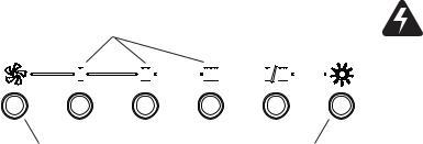
PARTS INCLUDED WITH HOOD
|
Shielded Halogen Bulbs |
Micromesh Grease Filters |
(120 V, 50 W max., MR16 or |
(2 per hood) |
PAR16 with GU10 base) |
|
(2 per hood) |
|
3¼” x 10” |
7” Round |
|
Damper / Duct |
Duct Connector |
|
Connector |
|
|
OR |
EZ-1 One person Installation Kit |
8” |
O |
|
C |
OU |
|
|
|
|
|
7½” |
(including template for |
|
10½” |
ducting, printed both sides, |
|
4¼” |
|
|
14½” |
and installation brackets) |
C |
C |
|
|
Appuyer ce bord au mur arrière |
|
Parts Bag
(4 no. 8-18 x 1/2" metal screws,
4 washers, 6 no. 8 x 5/8" round head wood screws, 6 no. 8 x 1/2" countersunk wood screws, 1 suction cup tool)
PARTS NOT INCLUDED WITH HOOD*
OPTIONAL PARTS (purchase separately)
Non-Ducted Recirculation Filters
(Non-ducted hoods only)
(2 per hood) Part Nos.:
S97020466 (30-in. width hoods)
S97020467 (36-in. width hoods)
7-inch Round Damper
(For use with 7-inch Round Duct) Sears Part No. 59183
Ducting Accessories
(See “Equivalent Duct Length Chart” on page 6 for Ducting Accessory Model Nos.)
“Parts Not Included With Hood” available by calling Sears at 1-800-4-MY-HOME®
TOOLS NEEDED FOR HOOD INSTALLATION
|
Drill |
|
|
|
Screwdriver |
(with 1/8" and |
|
|
|
7/64" drill bits, |
|
|
|
|
(Flat & Phillips no. 2) |
|
|
|
|
and 1½" hole saw) |
Long Nose |
|
|
|
|
|
Metal Foil |
||
|
|
Pliers |
|
|
|
|
|
Duct Tape |
|
|
|
|
|
|
Pencil |
Tape |
|
|
|
Measure |
|
-or- |
|
|
|
|
|
||
|
|
|
Keyhole |
|
|
|
|
|
|
|
|
Sabre Saw |
|
Saw |
HR0064 |
Wire |
|
Sheet Metal |
||
Stripper |
||
Shears |
||
|
||
|
5 |
Warranty
Safety
Operation
Cleaning
Installation
Parts Service
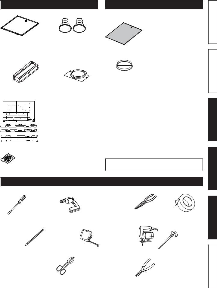
EQUIVALENT DUCT LENGTH CHART
Kenmore range hoods are designed to perform e ciently when attached to long runs of duct. As a point of reference, this hood will function at approximately 80% of its rated air flow when 25 equivalent feet of 7" round ductwork is attached. Use this chart to calculate the equivalent duct length of your system.
Broan Model 401
Straight Duct 3¼-in. x 10-in. x 2-ft. long
Equivalent length
2 ft.
Broan Model 407
Straight Duct 7-in. round x 2-ft. long
Equivalent length
2 ft.
Broan Model 415
7-in. Round Elbow
Equivalent length
8 ft.
Broan Model 412H 3¼-in. x 10-in. to 7-in. Round Transition
Equivalent length
5.5 ft.
Broan Model 428 3¼-in. x 10-in.
Right-angle Elbow
Equivalent length
8.5 ft.
Broan Model 429 3¼-in. x 10-in.
Right-angle Flat Elbow
Equivalent length
24 ft.
Broan Model 430 3¼-in. x 10-in.
Right-angle
Short
Eave Elbow
Equivalent length
15 ft.
Broan Model 431 3¼-in. x 10-in.
Right-angle
Long
Eave Elbow
Equivalent length
15 ft.
Broan Model 647
7-in. Round
Wall Cap
Equivalent length
34 ft.
(6-ft. w/o damper)
Sears Model 59391 3¼-in. x 10-in. Wall Cap


 Equivalent length
45 ft.
(7-ft. w/o damper)
Sears
Model 59091
Roof Cap (accepts 7-in. round
or 3¼-in. x 10-in. duct)
Equivalent length
30 ft. (7-ft. w/o damper)
Sears Model “Ducting Accessories” available by calling: Sears at 1-800-4-MY-HOME®
Broan Model “Ducting Accessories” available by calling: 1-800-558-1711.
6
|
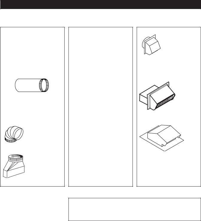
INSTALL DUCTWORK (DUCTED INSTALLATION ONLY) |
|
|||
|
|
|
|
|
Warranty |
1. |
Determine whether hood will discharge vertically |
ROOF CAP |
|
||
|
|
||||
|
(3¼” x 10” or 7” Round) or horizontally (3¼” x 10” |
3¼" X 10" OR |
|
||
|
only). |
|
|
7" ROUND DUCT |
|
2. |
Run ductwork between the hood location and a roof |
|
|
(FOR VERTICAL |
|
|
cap or wall cap. |
|
|
DISCHARGE) |
|
3. |
Choose a straight, short duct run to allow the hood to |
SOFFIT |
|
|
|
|
perform most e ciently. Long duct runs, elbows and |
|
HOUSE WIRING |
|
|
|
transitions will reduce the performance of the hood. |
CABINET |
(TOP OR BACK OF HOOD) |
|
|
|
Use as few of them as possible. When possible, use |
|
WALL CAP |
|
|
|
at least 2 foot straight runs before any turns. Larger |
HOOD |
|
|
|
|
ductwork may be required for best performance with |
|
|
||
|
|
3¼" X 10" DUCT |
Safety |
||
|
longer duct runs. |
|
|||
|
18" MIN - 24" MAX |
(FOR HORIZONTAL DISCHARGE) |
|||
4. |
Install wall cap or roof cap (sold separately); ensure |
||||
|
|||||
ABOVE COOKING SURFACE |
|
|
|||
|
there is no leak in hoiouse insulation. Connect metal |
NOTE: Distances over 24” are at the installer and user |
|
||
|
ductwork to cap and work back towards the hood |
|
|||
|
discretion. |
|
|
||
|
location. Use 2” metal foil duct tape to seal the joints |
|
|
||
|
between ductwork sections. |
|
|
|
|
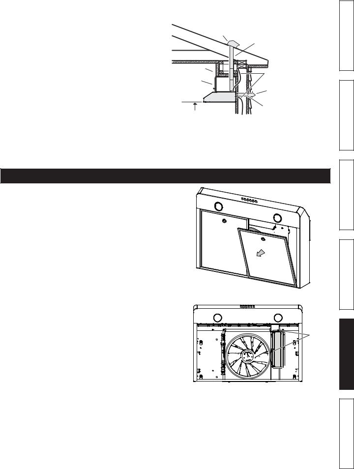
PREPARE THE HOOD
1. If present, remove all protective polyfilm from the hood and/or parts. Using the finger cup, remove the Micromesh Filters from the hood by pushing down and tilting filters out.
B


C
2. Remove the EZ1 brackets from inside the hood by |
|
cutting o the tie wrap. Remove both screws holding |
|
damper assembly to hood. Remove parts bag |
|
(captured behind the damper assembly). Remove |
|
damper assembly from inside the hood and keep |
|
the screws for further use. |
EZ1 |
BRACKETS


SCREWS


 DAMPER
 ASSEMBLY
7
Operation
Cleaning
Installation
Parts Service
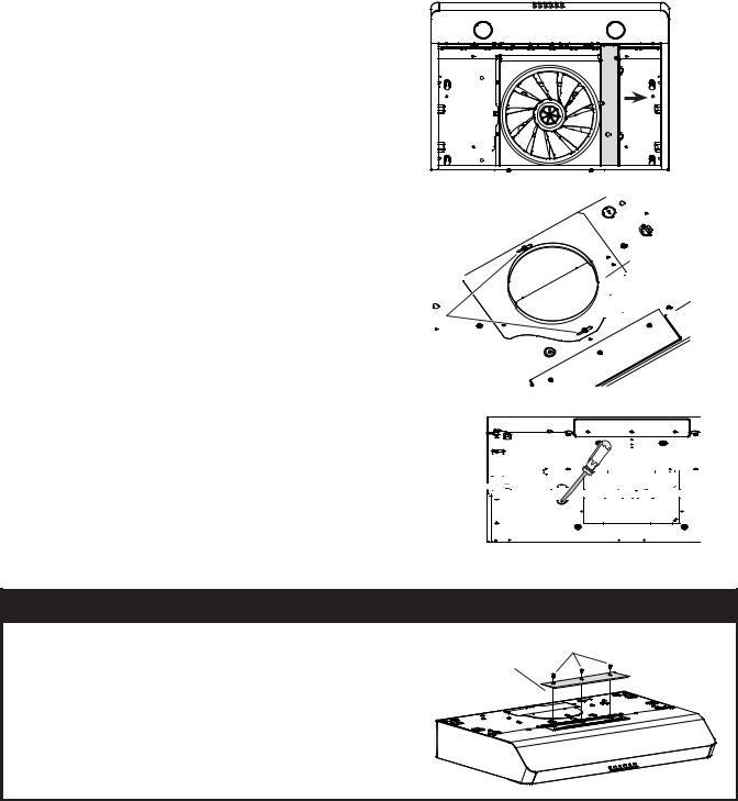
3. Remove the wiring cover (shaded part on illustration beside) by sliding it out from the hood and set it aside.
4. Remove 7” Round Duct Plate from top/back of hood (see illustration beside).
7” ROUND


 DUCT PLATE 2 SCREWS


5.Remove Electrical Power Cable Knockout from top (vertical exhaust) or back (horizontal exhaust) of hood. Install an appropriate strain relief, 1/2” diameter (not included).
ELECTRICAL 


 POWER CABLE


 KNOCKOUT


NON-DUCTED INSTALLATIONS ONLY
6. Remove 3 screws retaining the recirculation cover |
RECIRCULATION |
SCREWS |
plate (shaded part in illustration beside) to the hood. |
|
|
COVER PLATE |
|
|
Discard this plate with its screws. |
|
|
|
|
8

DUCTED INSTALLATIONS ONLY
7.Remove 3¼” x 10” vertical, 3¼” x 10” horizontal, or 7-inch round knockout plate as appropriate for your ducting method (see FIGURES 1 A and 1 B).
FIGURE 1 A |
|
7” ROUND |
|
KNOCKOUT PLATE |
|
(ALSO REMOVE VERTICAL |
|
KNOCKOUT PLATE) |
|
3¼” X 10” |
|
VERTICAL |
|
KNOCKOUT |
3¼” X 10” |
PLATE |
HORIZONTAL |
|
KNOCKOUT |
|
PLATE |
FIGURE 1 B |
8.Attach 3¼” x 10” Damper Assembly on top OR back of hood (if using 3¼” x 10” duct; shaded part in FIGURE 2 A) or 7” Round Duct Plate (if using 7-inch round duct, FIGURE 3) over the knockout opening. When installed, the 3¼” x 10” damper assembly must open as shown in FIGURE 2 B.
FIGURE 2 A |
SCREWS |
FIGURE 2 B |
3¼” X 10” |
|
|
|
DAMPER |
|
DAMPER |
|
|
|
FLAP |
|
ASSEMBLY |
|
|
|
PIVOT |
|
|
|
|
|
|
TOP/BACK |
|
|
EDGE OF |
|
|
HOOD |
|
|
BACK OF |
|
SCREWS |
HOOD |
|
|
|
3¼” X 10” |
|
DAMPER |
DAMPER |
|
FLAP |
ASSEMBLY |
|
PIVOT |
FIGURE 3
7” ROUND
DUCT
PLATE
SCREWS
NOTE: To accommodate o -center ductwork, the 7” round duct plate can be installed up to 1/2” on either side of the hood center.
TIP: Insert a small length of duct over the 3¼” x 10” damper assembly (for rectangular ducting) or 7” round (for round ducting) and seal the joint using aluminum foil duct tape to ease connection with the house ductwork.
9
Warranty
Safety
Operation
Cleaning
Installation
Parts Service
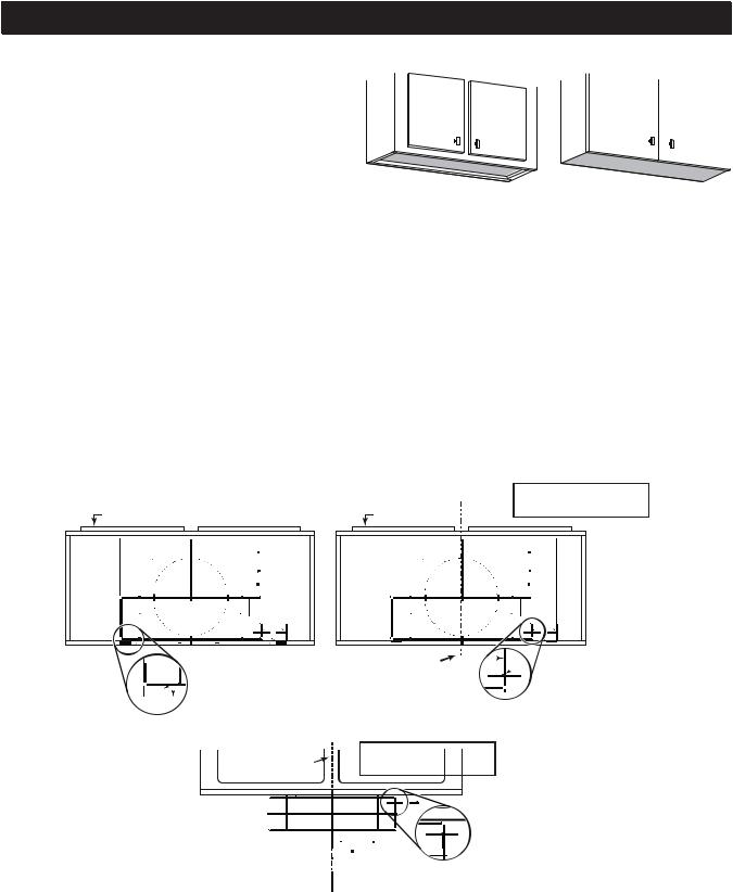
PREPARE THE HOOD LOCATION
NOTE: Before starting installation, read all the steps |
FRAMED CABINET |
FRAMELESS CABINET |
of these instructions. |
|
|
Use the illustration beside to identify your kitchen cabinet type.
This manual covers 2 kinds of installation: the standard (without EZ1 brackets) and the EZ1 one-person installation system (using included template and brackets). For the standard installation, go to page 14.
EZ1 One-person installation system
EZ1 installation is designed for use with kitchen cabinets that have the same width designation as the range hood width. If the cabinet is greater than 1/2” wider than the range hood width, please use the standard installation method.
1.Use the proper template for vertical OR horizontal disharge (included) for placement of ductwork and electrical cutout in cabinet or wall. For a non-ducted installation, DO NOT cut a duct access hole, only cut the hole for electrical wiring. If replacing a hood and plan to use the existing duct and electrical, steps 2 to 5 may not be necessary. If so, skip to step 6.
2.Measure and mark the hood center line on cabinet bottom.
3.Align the center line on template with the hood center line marked on the bottom of the cabinet, placing the edge (where indicated) of the template against back wall. When using with framed cabinet for vertical exhaust installation, fold over rear edge of template equal to the depth of the cabinet frame at the wall (use graduations on template, C locations on template). Tape the template in place.
NOTE: When facing the installation, A and B (on template) must be at right.
CABINET FRONT |
CABINET FRONT |
VERTICAL
EXHAUST DUCTING
|
|
|
|
|
|
|
|
|
|
|
|
|
M |
|
|
|
|
|
|
|
|
|
|
|
|
|
|
|
|
|
|
|
|
M |
|
|
|
|
|
||
|
|
|
|
|
|
|
|
|
|
|
|
|
7” R D |
OR |
R D |
|
|
|
|
|
|
|
|
|
|
|
|
|
|
|
7” R D |
OR |
R D |
||||||||
C |
|
|
|
|
|
|
|
|
|
|
|
M |
|
|
|
|
|
|
C |
|
|
|
|
|
|
|
|
|
|
|
|
M |
|
|
|
|
|
||||
|
|
|
|
|
|
|
|
|
|
|
|
|
|
|
|
|
|
|
|
|
|
|
|
|
|
|
|
|
|
|
|
|
|
||||||||
|
|
|
|
|
|
|
|
|
|
|
C |
7 |
OU |
C |
|
|
|
|
|
|
|
|
|
|
|
|
|
C |
7 |
OU |
C |
||||||||||
|
|
|
|
|
|
|
|
T |
|
S |
|
|
|
|
|
|
|
|
|
|
|
|
|
|
|
|
|
|
T |
|
S |
|
|
|
|||||||
|
|
|
8” |
|
|
|
|
|
|
|
|
8” |
|
|
|
|
|||||||||||||||||||||||||
|
|
|
|
|
|
C |
7 . |
O |
|
|
|
|
|
|
|
|
|
|
C |
7 . |
O |
|
|
|
|||||||||||||||||
|
|
|
|
|
|
L |
C |
C |
|
|
|
|
|
|
|
L |
C |
C |
|||||||||||||||||||||||
|
|
|
|
|
|
|
|
|
|
|
|
|
|
|
|
|
|
|
|
|
|
|
|
|
|
|
|||||||||||||||
|
|
|
|
|
|
|
|
7½” |
|
|
|
|
|
|
|
|
|
|
|
|
|
|
|
|
|
|
|
7½” |
|
|
|
|
|
|
|
|
|
||||
|
|
|
|
|
|
|
|
|
|
|
|
|
|
|
|
|
|
|
|
|
|
|
|
|
|
|
|
|
|
||||||||||||
|
|
|
|
|
|
|
|
|
|
|
|
|
|
|
|
|
|
|
|
|
|
|
|
|
|
|
|
|
|
|
|
|
|
|
|
|
|
|
|
|
|
|
VE |
RTICAL EX |
HAUST |
|
|
VE |
RTICAL EX |
HAUST |
|||||||||||||||||||||||||||||||||
|
|
|
|
|
|
|
|
10½” |
|
|
|
|
4¼” |
|
|
|
|
|
|
|
|
|
|
|
|
|
10½” |
|
|
|
|
4¼” |
|
|
|
||||||
|
|
|
|
|
|
|
|
|
|
|
|
|
|
|
|
|
|
|
|
|
|
|
|
|
|
|
|
|
|
|
|||||||||||
|
|
|
|
|
|
|
|
|
|
|
|
|
|
|
|
|
|
|
|
|
|
|
|
|
|
|
|
|
|
|
|
|
|
|
|
|
|
||||
|
|
|
|
|
14½” |
|
|
|
|
|
|
|
|
|
|
A B |
|
|
|
|
|
|
14½” |
|
|
|
|
|
|
|
|
|
|
A B |
|||||||
|
C |
|
|
|
|
|
|
|
|
|
|
|
|
|
|
|
|
|
C |
|
|
|
|
|
|
|
|
|
|
|
|
|
|
|
|
||||||
|
|
|
|
|
|
|
|
|
|
|
|
C |
|
|
|
|
|
|
|
|
|
|
|
|
|
C |
|||||||||||||||
|
|
|
|
|
|
|
|
|
|
|
|
|
|
|
|
|
|
|
|
|
|
|
|
|
|
|
|
|
|
|
|
|
|
|
|
|
|
|
|
|
|
Place this edge against back wall Appuyer ce bord au mur arrière Apoyar este borde contra la pared de atrás
|
|
|
C |
|
CENTER LINE |
|
A |
ELECTRICAL |
|
|
|
|
|
||||
|
|
|
|
FOLD TEMPLATE ALONG GRADUATED |
|
C |
ACCESS HOLE |
|
|
|
|
|
|
SCALE WHEN INSTALLING TO FRAMED |
|
LOCATION (A) |
|
|
|
|
|
|
|
|
(IN CABINET BOTTOM) |
|
|
|
|
|
P |
|
|
||
|
|
|
|
|
|
|||
|
|
|
|
|
CABINET. |
|
|
|
|
|
|
|
|
|
|
|
|
CENTER LINE |
HORIZONTAL |
EXHAUST DUCTING |
|
|
|
|
|
Place this edge against |
A |
B |
cabinet bottom. |
||
Appuyer ce bord contre le bas |
|
|
de l’armoire. |
|
|
Apoyar este borde contra |
|
|
la base del armario. |
|
|
C |
|
L |
|
M |
M |
R D |
C |
T |
S |
C |
|
 A
A
Electrical access hol A = single blower ho B = double blower
HORIZONTAL EXHAUST
Centre du tr d’alim
ELECTRICAL ACCESS HOLE LOCATION (A)
(IN WALL)
10
4.Drill a 1/8” dia. pilot hole for house wiring, at A location on template.
5.Use a sharp pencil or 1/8” drill bit to mark the locations for the appropriate duct access holes
(16 locations for 7” round duct, or 4 corner locations for rectangular duct). Remove the template.
FRAMED CABINET
Refer to the marking on the brackets to determine the correct installation side and orientation.
X
6.Draw the border for the exhaust ducting by linking its marks (16 for round duct and 4 for rectangular duct), then cut the opening in the cabinet bottom (vertical exhaust) or in the wall (horizontal exhaust). Drill the house wiring hole by using a 1½” hole saw centered with the pilot hole previously made in 4.
7.Install the proper installation brackets according to the type of cabinet (framed or frameless). See below.
Y
7/64”
Warranty
Safety
Operation
Cleaning
Z
Installation
Mate the corresponding bracket to the cabinet side frame, while placing rear end of bracket against the wall. Use a pencil to mark 3 holes
(there are 6 holes but only 3 are necessary).
Remove the bracket. Using a 7/64” drill bit, drill 3 holes where marked.
Assemble the bracket to the side frame using a
Phillips screwdriver and 3 provided no. 8 x 5/8” wood screws. Repeat for the other side frame.
11
Parts Service
 Loading...