


Kenmore Elite 175607930, 175607931, 175605811, 175605810, 175605590 Owner’s Manual
...
f
®
FOOD WASTE DISPOSERS
Installation, Care & Use Manual
TOOLS AND MATERIALS YOU WILL NEED:
Slotted Screwdriver, Adjustable Pliers, Plumber's Putty,
Electrical Tape
TOOLS, MATERIALS, AND ACCESSORIES
YOU MAY NEED:
Phillips Screwdriver, Drain Auger, 3/8" Electrical Clamp
Connector, Wire Nuts (2), Second 1 1/2" Drain Trap,
Hammer, Hacksaw, Water Hose Clamp, Pipe Wrench,
Copper Ground Wire, Dishwasher Drain Connection Kit, Air
Gap, Electrical On/Off Switch, Drain Tube Extension
(_/A
JlB
O--c
Read through the entire Installation, Care
& Use manual before installing the dis-
poser. Determine which of the tools,
materials, and accessories you will need
before you begin. Make sure you have all
necessary disposer parts before install-
ing the disposer (see part identification
diagram below).
_ @-N
#1 .-0
OR
O--G
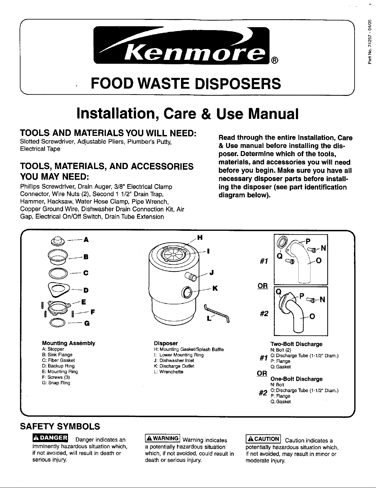
Mounting Assembly
A: Stopper
B: SinkFlange
C: Fiber Gasket
D: Backup Ring
E: Mounting Ring
F: Screws (3)
G: Snap Ring
SAFETY SYMBOLS
Danger indicates an
imminently hazardous situation which,
if not avoided, will result in death or
serious injury.
Disposer
H: Mounting Gasket/Splash Baffle
1: Lower Mounting Ring
J: Dishwasher Inlet
K: Discharge Outlet
L: Wrenchette
It" WARNINGIWarning indicates
a potentially hazardous situation
which, if not avoided, could result in
death or serious injury.
--#2 ___N
Two-Bolt Discharge
N: Bolt (2)
_10: DischargeTube (1-1/2" Diam.)
P: Flange
Q:Gasket
OR
One-Bolt Discharge
N: Bolt
#20:DischargeTube(1-1/2" Diam.)
P: Flange
Q:Gasket
[_kCAUTION] Caution indicates a
potentially hazardous situation which,
if not avoided, may result in minor or
moderate injury,
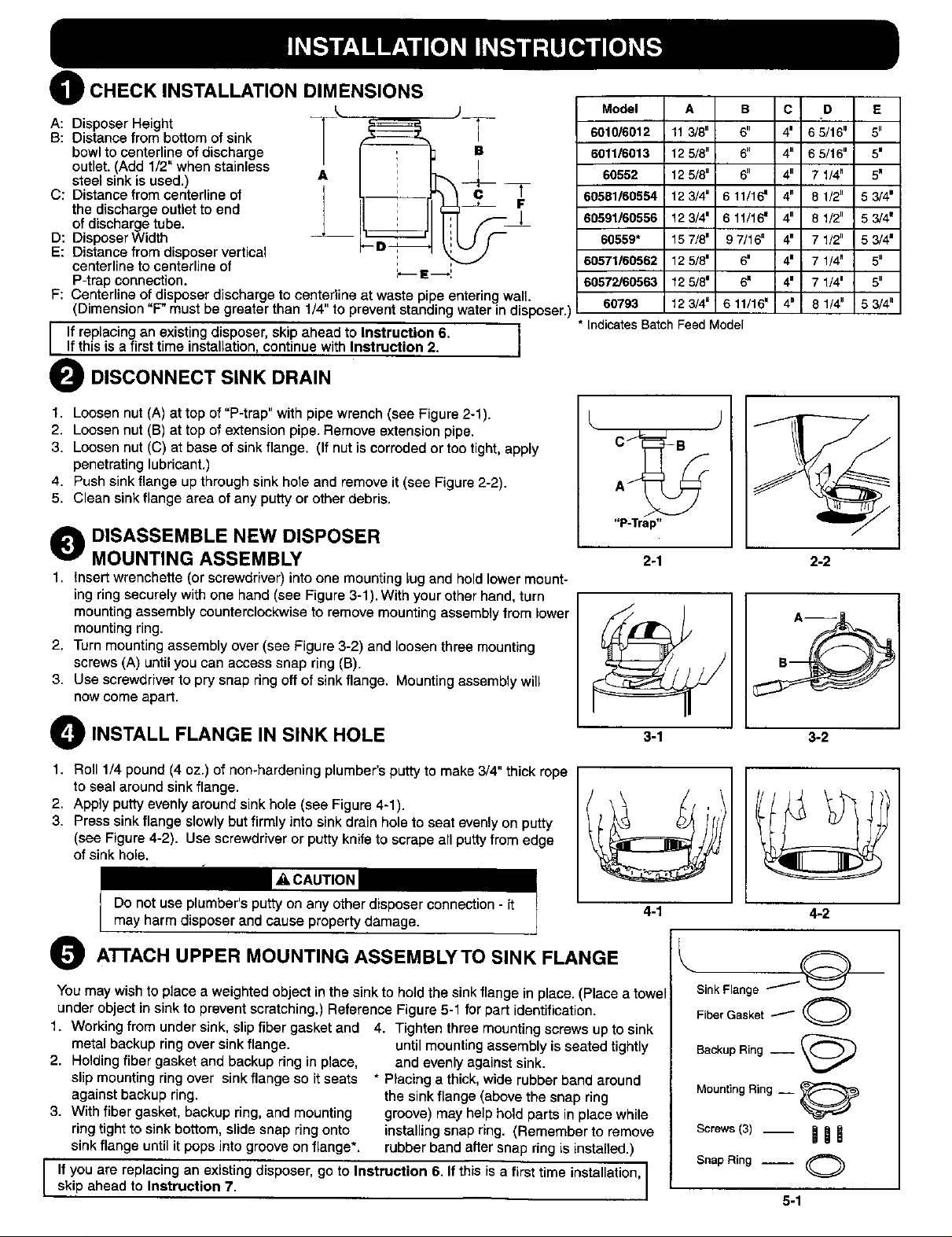
) CHECK INSTALLATION DIMENSIONS
@
A: Disposer Height
B: Distance from bottom of sink
bowl to centerline of discharge
outlet. (Add 1/2" when stainless
steel sink is used.)
C: Distance from centerline of
the discharge outlet to end
of discharge tube.
D: Disposer Width
E: Distance from disposer vertical
centerline to centerline of
P-trap connection.
F: Centerline of disposer discharge to centerline at waste pipe entering wall
(Dimension "F" must be greater than 1/4" to prevent standing water in disposer.)
i f replacing an existing disposer, skip ahead to Instruction 6. I
If this is a first time installation, continue with Instruction 2.
i
,',,--I__I
B
O DISCONNECT SINK DRAIN
Model A B C D E
601016012 11 3/8" 6" 4' 6 5/16" 5"
6011/6013 12 5/8" 6" 4" 6 5/16" 5'
60552 12 5/80 6" 4" 7 1/4" 5_
60581/60554 12 3/4" 6 11/16= 4" 8 1/2" 6 3/4m
60691/60556 12 3/4 = 6 1t/16 m 4" 8 1/2" 5 3/4'
60559* 15 7/8 = 9 7/16" 4" 7 1/2" 5 3/4'
60571/60562 12 5/8' 6" 4 = 7 1/4" 5"
60572/60563 12 5/8" 6" 4' 7 1/4= 5"
60793 12 3/4" 6 11/16 = 4" 8 1/4" 5 3/4"
• Indicates Batch Feed Model
I
1. Loosen nut (A) at top of "P-trap" with pipe wrench (see Figure 2-1).
2. Loosen nut (B) at top of extension pipe. Remove extension pipe.
3. Loosen nut (C) at base of sink flange. (If nut is corroded or too tight, apply
penetrating lubricant,)
4. Push sink flange up through sink hole and remove it (see Figure 2-2).
5. Clean sink flange area of any putty or other debris.
O DISASSEMBLE NEW DISPOSER
MOUNTING ASSEMBLY
1. insert wrenchette (or screwdriver) into one mounting lug and hold lower mount-
ing ring securely with one hand (see Figure 3-1). With your other hand, turn
mounting assembly counterclockwise to remove mounting assembly from lower
mounting ring.
2, Turn mounting assembly over (see Figure 3-2) and loosen three mounting
screws (A) until you can access snap ring (B).
3. Use screwdriver to pry snap ring off of sink flange. Mounting assembly will
now come apart.
O INSTALL FLANGE IN SINK HOLE
1. Roll 1/4 pound (4 oz.) of non-hardening plumber's putty to make 3/4" thick rope
to seal around sink flange.
2. Apply putty evenly around sink hole (see Figure 4-1).
3. Press sink flange slowly but firmly into sink drain hole to seat evenly on putty
(see Figure 4-2). Use screwdriver or putty knife to scrape all putty from edge
of sink hole.
"P-Trap"
2-1
9
/
2-2
O ATTACH UPPER MOUNTING ASSEMBLYTO SINK FLANGE
You may wish to place a weighted object in the sink to hold the sink flange in place. (Place a towel
under object in sink to prevent scratching.) Reference Figure 5-1 for part identification.
1. Working from under sink, slip fiber gasket and 4. Tighten three mounting screws up to sink
metal backup ring over sink flange.
2. Holding fiber gasket and backup ring in place,
slip mounting ring over sink flange so it seats
against backup ring.
3. With fiber gasket, backup ring, and mounting
ring tight to sink bottom, slide snap ring onto
sink flange until it pops into groove on flange*.
I f you are replacing an existing disposer, go to Instruction 6. If this is a first time installation,
skip ahead to Instruction 7.
until mounting assembly is seated tightly
and evenly against sink.
* Placing a thick, wide rubber band around
the sink flange (above the snap ring
groove) may help hold parts in place while
installing snap ring. (Remember to remove
rubber band after snap ring is installed.)
4-1
- O--
SinkFlange
FiberGasket_ O
BackupRing-- _)
MountingRing __
Screws(3)_ BiB
SnapRing -- O
4-2
5-1

O REMOVE EXISTING DISPOSER
1, Turn off electrical power at fuse box or circuit breaker.
_WARNING
Personal Injury
• Do not position your head or body under disposer; unit could fall
during removal or installation.
2. Disconnect drain trap from disposer waste discharge tube with adjustable pliers
(see Fig. 6-1). (Also disconnect dishwasher drain connection, if required.)
3. Support disposer with one hand and insert end of wrenchette or screwdriver
into right side of one mounting lug on lower mounting ring (see Figure 6-2).
Lift disposer slightly and loosen lower mounting ring by pushing or pulling
wrenchette or screwdriver to left until disposer is free from mounting assembly.
(Disposer may be heavy - provide support.)
4. With electrical supply turned off, turn disposer upside down and remove electri-
cal cover plate (see Figure 6-3). Loosen green ground screw and remove
wire nuts (see Figure 6-4). Disconnect disposer wires from electrical supply
wires. Loosen screw(s) on electrical clamp connector and remove wires from
disposer.
Ifthe new disposer mounting is the same as old one, remove mounting assembly I
from disposer (Instruction 3) and go to Instruction 7.
• If the new disposer mounting is different from the old one (or you wish to replace I
the old sink flange) you must complete Steps 5 - 6 (below), and Instructions 2 - |
5, then continue with Instruction 7.
5. Loosen three mounting screws, pry snap ring off with screwdriver, and remove
old mounting assembly (see Figure 6-5). (Some mounting assembly removal
requires additional tools.)
6. Push old sink flange up through sink hole (see Figure 6-6). Use screwdriver or
putty knife to scrape all old putty from edge of sink hole.
J
6-1
6-3
6-5
6-2
O CLEAN SINK DRAIN LINE
Failure to clean sink drain line may result in drain line blockage.
1. Remove P-trap.
2. With drain auger, clear all hardened waste material in horizontal drain line.
you
If are not connecting a dishwasher to disposer, to Instruction 9. 1
O PREPARE DISHWASHER DRAIN CONNECTION (IF
APPLICABLE)
The knockout drain plug should only be removed if you are connecting
a built-in dishwasher to the disposer. NOTE: If the dishwasher
connection is made without removing the plug, the dishwasher may
overflow. (Connections must comply with local plumbing codes.)
Remove Knockout Plug
1. Lay disposer on its side and insert screwdriver into dishwasher inlet so tip rests
on outer edge of knockout plug.
2. Tap end of screwdriver handle with hammer until molded plug breaks loose
(see Figure 8-1).
3. REMOVE LOOSE KNOCKOUT PLUG FROM INSIDE DISPOSER.
Attach Dishwasher Drain Connector
If your dishwasher drain hose is 7/8" diameter, go to Instruction 9.
If your dishwasher drain hose is not 7/8" diameter, you must attach a dishwasher
drain connector to the dishwasher drain inlet. Follow the installation instructions
with the connection kit. (You will connect the dishwasher drain hose to the
connector in Instruction 12.) 3
go
J
 Loading...