


Kenmore Elite 11095861400, 11095862400, 11095866400, 11095871400, 11095872400 Owner’s Manual
...
E / ! T E
HE4 HE5
Gas Dryer
Secadora a Gas
Models/Modelos 110.9586#, 9587#
# = color number/nQmero de color
®
8562130 Sears Roebuck and Co., Hoffman Estates, IL 60179 U.S.A. www.sears.com
TABLEOF CONTENTS
PROTECTION AGREEMENTS
PROTECTION AGREEMENTS ....................................................... 2
WARRANTY ..................................................................................... 3
PEDESTAL OPTION WARRANTY ................................................. 3
DRYER SAFETY .............................................................................. 4
INSTALLATION INSTRUCTIONS .................................................. 6
Tools and Parts ............................................................................ 6
Optional Pedestal ......................................................................... 6
Location Requirements ............................................................... 6
Electrical Requirements ................................................................ 8
Gas Supply Requirements ........................................................... 8
Venting Requirements .................................................................. 9
Plan Vent System ...................................................................... 10
Install Vent System .................................................................... 11
Install Leveling Legs .................................................................. 12
Level Dryer ................................................................................. 12
Make Gas Connection ............................................................... 12
Connect Vent ............................................................................. 13
Reverse Door Swing .................................................................. 13
Complete Installation ................................................................. 14
DRYER USE ................................................................................. 15
Starting Your Dryer .................................................................... 15
Stopping Your Dryer .................................................................. 16
Pausing or Restarting ................................................................ 16
Control Locked .......................................................................... 16
Loading ...................................................................................... 16
Drying and Cycle Tips ............................................................... 16
Status Lights .............................................................................. 17
Cycles ........................................................................................ 17
Options ...................................................................................... 18
Modifiers .................................................................................... 18
Changing Cycles, Options and Modifiers ................................. 19
End of Cycle Signal ................................................................... 19
TUMBLE FREETM Heated Dryer Rack ....................................... 19
DRYER CARE .............................................................................. 20
Cleaning the Dryer Location ...................................................... 20
Cleaning the Lint Screen ........................................................... 20
Cleaning the Dryer Interior ........................................................ 21
Removing Accumulated Lint ..................................................... 21
Vacation and Moving Care ........................................................ 21
Changing the Drum Light .......................................................... 21
TROUBLESHOOTING .................................................................. 21
SERVICE NUMBERS ............................................... BACK COVER
Master Protection Agreements
Congratulations on making a smart purchase. Your new
Kenmore ®product is designed and manufactured for years of
dependable operation. But like all products, it may require
preventive maintenance or repair from time to time. That's when
having a Master Protection Agreement can save you money and
aggravation.
Purchase a Master Protection Agreement now and protect
yourself from unexpected hassle and expense.
The Master Protection Agreement also helps extend the life of
your new product. Here's what's included in the Agreement:
if Expert service by our 12,000 professional repair specialists
V' Unlimited service and no charge for parts and labor on all
covered repairs
if "No-lemon" guarantee - replacement of your covered
product if four or more product failures occur within twelve
months
if Product replacement if your covered product can't be fixed
if Annual Preventive Maintenance Check at your request - no
extra charge
if Fast help by phone - phone support from a Sears technician
on products requiring in-home repair, plus convenient repair
scheduling
if Power surge protection against electrical damage due to
power fluctuations
if Rental reimbursement ifrepair of your covered product takes
longer than promised
Once you purchase the Agreement, a simple phone call is all that
it takes for you to schedule service. You can call anytime day or
night, or schedule a service appointment online.
Sears has over 12,000 professional repair specialists, who have
access to over 4.5 million quality parts and accessories. That's
the kind of professionalism you can count on to help prolong the
life of your new purchase for years to come. Purchase your
Master Protection Agreement today!
Some limitations and exclusions apply. For prices and
additional information, call 1-800-827-6655.
Sears Installation Service
For Sears professional installation of home appliances, garage
door openers, water heaters, and other major home items, in the
U.S.A. call 1-800-4-MY-HOME _.
2
WARRANTY
PEDESTAL OPTION
FULL ONE-YEAR WARRANTY ON MECHANICAL AND
ELECTRICAL PARTS
For one year from the date of purchase, when this dryer is
installed and operated according to the instructions provided in
this Use and Care Guide, Sears will repair this dryer, free of
charge, if defective in materials or workmanship.
NOTE: Exhausting this dryer with a plastic vent can void this
warranty. See "Installation Instructions" for the complete exhaust
requirements for this dryer.
Limited Two-Year Warranty on SENSOR SMART TM
Electronic Control Board
For the second year from the date of purchase, Sears will replace
the electronic control board if defective in material or
workmanship. You will be charged for labor after the first year.
Warranty Restriction
If the dryer is subject to other than private family use, the above
warranty coverage is effective for only 90 days.
Warranty Service
Warranty service is available by contacting the nearest Sears
Service Center. This warranty applies only while the product is in
use in the United States.
This warranty gives you specific legal rights and you may also
have other rights which vary from state to state.
For Sears Warranty information or to contact a Sears Service
Center, please refer to the service numbers located on the back
page of this manual.
Sears, Roebuck and Co.
D/817WA, Hoffman Estates, IL 60179
WARRANTY
Full One-Year Warranty on Mechanical Parts
For one year from the date of purchase, supplier will repair or
replace any of its mechanical parts if defective in material or
workmanship. This Pedestal must be installed with this dryer
according to the instructions provided in the Pedestal Installation
Instructions.
Warranty Restriction
If the Pedestal is subject to other than private family use and/or
used with any other product than those listed in the installation
instructions, this warranty is null and void.
In the space following, record your complete model number,
serial number, and purchase date. You can find this information
on the model and serial number label.
Have this information available to help you quickly obtain
assistance or service when you contact Sears concerning your
appliance.
Model number 110,
Serial number
Purchase date
Save these instructions and your sales receipt for future
reference.
Product Record
In the space following, record your complete model number,
serial number, and purchase date. You can find this information
on the model and serial number label, located at the top inside
dryer door well.
Have this information available to help you quickly obtain
assistance or service when you contact Sears concerning your
appliance.
Model number 110.
Serial number
Purchase date
Save these instructions and your sales receipt for future
reference.
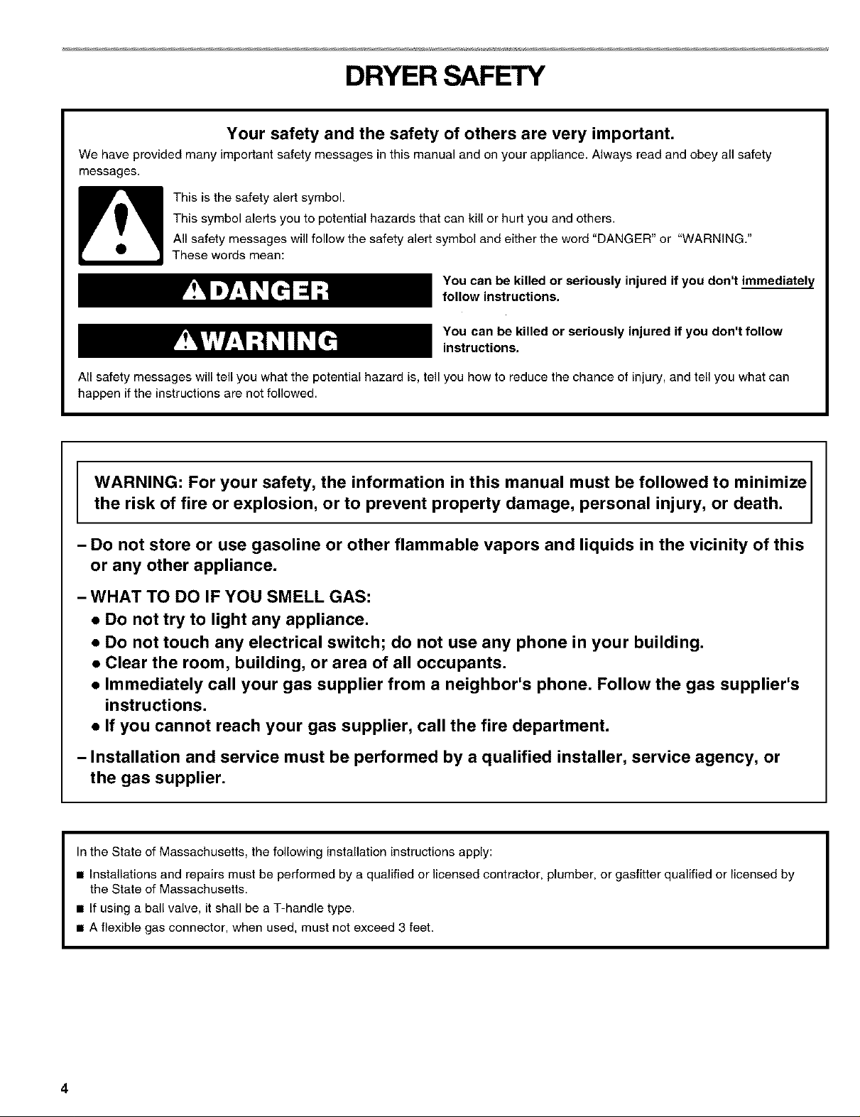
DRYER SAFETY
Your safety and the safety of others are very important.
We have provided many important safety messages in this manual and on your appliance. Always read and obey all safety
messages.
This is the safety alert symbol.
This symbol alerts you to potential hazards that can kill or hurt you and others.
All safety messages will fellow the safety alert symbol and either the word "DANGER" or "WARNING."
These words mean:
You can be killed or seriously injured if you don't immediateLY
follow instructions,
You can be killed or seriously injured if you don't follow
instructions,
All safety messages will tell you what the potential hazard is, tell you how to reduce the chance of injury, and tell you what can
happen if the instructions are net followed.
WARNING: For your safety, the information in this manual must be followed to minimize
the risk of fire or explosion, or to prevent property damage, personal injury, or death.
- Do not store or use gasoline or other flammable vapors and liquids in the vicinity of this
or any other appliance.
- WHAT TO DO IF YOU SMELL GAS:
• Do not try to light any appliance.
• Do not touch any electrical switch; do not use any phone in your building.
• Clear the room, building, or area of all occupants.
• Immediately call your gas supplier from a neighbor's phone. Follow the gas supplier's
instructions.
• If you cannot reach your gas supplier, call the fire department.
- Installation and service must be performed by a qualified installer, service agency, or
the gas supplier.
In the State of Massachusetts, the following installation instructions apply:
• Installations and repairs must be performed by a qualified or licensed contractor, plumber, or gasfitter qualified or licensed by
the State of Massachusetts.
• If using a ball valve, it shall be a T-handle type.
• A flexible gas connector, when used, must net exceed 3 feet.
4
IMPORTANT SAFETY INSTRUCTIONS
WARNING: To reduce the risk of fire, electric shock, or injury to persons when using the dryer, follow basic precautions,
including the following:
• Read all instructions before using the dryer. • Do not repair or replace any part of the dryer or attempt
• Do not place items exposed to cooking oils in your dryer, any servicing unless specifically recommended in this
Items contaminated with cooking oils may contribute to Use and Care Guide or in published user-repair instruc-
a chemical reaction that could cause a load to catch fire. tions that you understand and have the skills to carry out.
• Do not dry articles that have been previously cleaned in,
washed in, soaked in, or spotted with gasoline, dry-
cleaning solvents, other flammable, or explosive
substances as they give off vapors that could ignite or
explode.
• Do not allow children to play on or in the dryer. Close
supervision of children is necessary when the dryer is
used near children.
• Before the dryer is removed from service or discarded,
remove the door to the drying compartment.
• Do not reach into the dryer if the drum is moving.
• Do not install or store the dryer where it will be exposed
to the weather.
• Do not tamper with controls.
SAVE THESE INSTRUCTIONS
• Do not use fabric softeners or products to eliminate static
unless recommended by the manufacturer of the fabric
softener or product.
• Do not use heat to dry articles containing foam rubber or
similarly textured rubber-like materials.
• Clean lint screen before or after each load.
• Keep area around the exhaust opening and adjacent sur-
rounding areas free from the accumulation of lint, dust,
and dirt.
• The interior of the dryer and exhaust vent should be
cleaned periodically by qualified service personnel.
• See installation instructions for grounding requirements.
IMPORTANT: The gas installation must conform with local codes, or in the absence of local codes, with the National Fuel Gas
Code, ANSI Z223.1/NFPA 54.
The dryer must be electrically grounded in accordance with local codes, or in the absence of local codes, with the National
Electrical Code, ANSI/NFPA 70.
INSTALLATIONINSTRUCTIONS
Check that you have everything necessary for correct installation.
Proper installation is your responsibility.
8" or 10" pipe wrench
8" or 10" adjustable
wrench (for gas
connections)
Flat-blade screwdriver •
Adjustable wrench that •
opens to 1" (2.54 cm) or
hex-head socket wrench
(for adjusting dryer feet)
Level •
_/4"nut driver or socket •
wrench
Parts supplied
Remove parts package from dryer drum. Check that all parts
were included.
• Knife
• Safety glasses
• Duct tape
Pipe-joint compound
resistant to L.R gas
Caulking gun and
compound (for installing
new exhaust vent)
Gloves
Pliers
1
4 Leveling legs
NOTE: Do not use leveling legs if installing the dryer on a
pedestal.
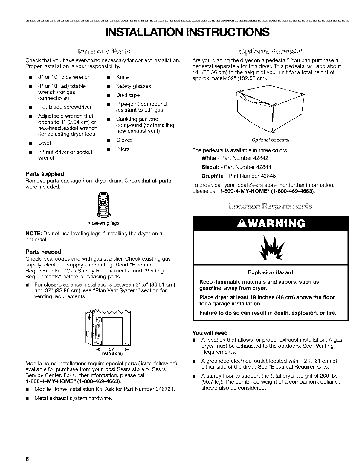
Are you placing the dryer on a pedestal? You can purchase a
pedestal separately for this dryer. This pedestal will add about
14" (35.56 cm) to the height of your unit for a total height of
approximately 52" (132.08 cm).
Optionalpedestal
The pedestal is available in three colors
White - Part Number 42842
Biscuit - Part Number 42844
Graphite - Part Number 42846
To order, call your local Sears store. For further information,
please call f-800-4-M¥-HOME e (1-800-469-4663).
,_0[ ....... _0 t,=*
Parts needed
Check local codes and with gas supplier. Check existing gas
supply, electrical supply and venting. Read "Electrical
Requirements," "Gas Supply Requirements" and "Venting
Requirements" before purchasing parts.
• For close-clearance installations between 31.5" (80.01 cm)
and 37" (93.98 cm), see "Plan Vent System" section for
venting requirements.
I_ 3T'
(93.99 cm
Mobile home installations require special parts (listed following)
available for purchase from your local Sears store or Sears
Service Center. For further information, please call
1-800-4-MY-HOME ®(f-800-469-4663).
• Mobile Home Installation Kit. Ask for Part Number 346764.
• Metal exhaust system hardware.
Explosion Hazard
Keep flammable materials and vapors, such as
gasoline, away from dryer.
Place dryer at least 18 inches (46 cm) above the floor
for a garage installation.
Failure to do so can result in death, explosion, or fire.
You will need
• A location that allows for proper exhaust installation. A gas
dryer must be exhausted to the outdoors. See "Venting
Requirements."
• A grounded electrical outlet located within 2 ft (61 cm) of
either side of the dryer. See "Electrical Requirements."
• A sturdy floor to support the total dryer weight of 200 Ibs
(96.7 kg). The combined weight of a companion appliance
should also be considered.
6
• A level floor with a maximum slope of 1" (2.5 cm) under entire
dryer. (If slope is greater than 1" [2.5 cm], install Extended
Dryer Feet Kit, Part No. 279810.) Clothes may not tumble
properly and automatic sensor cycles may not operate
correctly if dryer is not level.
• For a garage installation, you will need to place the dryer at
least 18" (46 cm) above the floor. If using a pedestal, you will
need an additional 6" (15.24 cm).
Do not operate your dryer at temperatures below 45°F (7°C). At
lower temperatures, the dryer might not shut off at the end of an
automatic cycle. Drying times can be extended.
The dryer must not be installed or stored in an area where it will
be exposed to water and/or weather.
Check code requirements. Some codes limit, or do not permit,
installation of the dryer in garages, closets, mobile homes, or
sleeping quarters. Contact your local building inspector.
NOTE: No other fuel-burning appliance can be installed in the
same closet as a dryer.
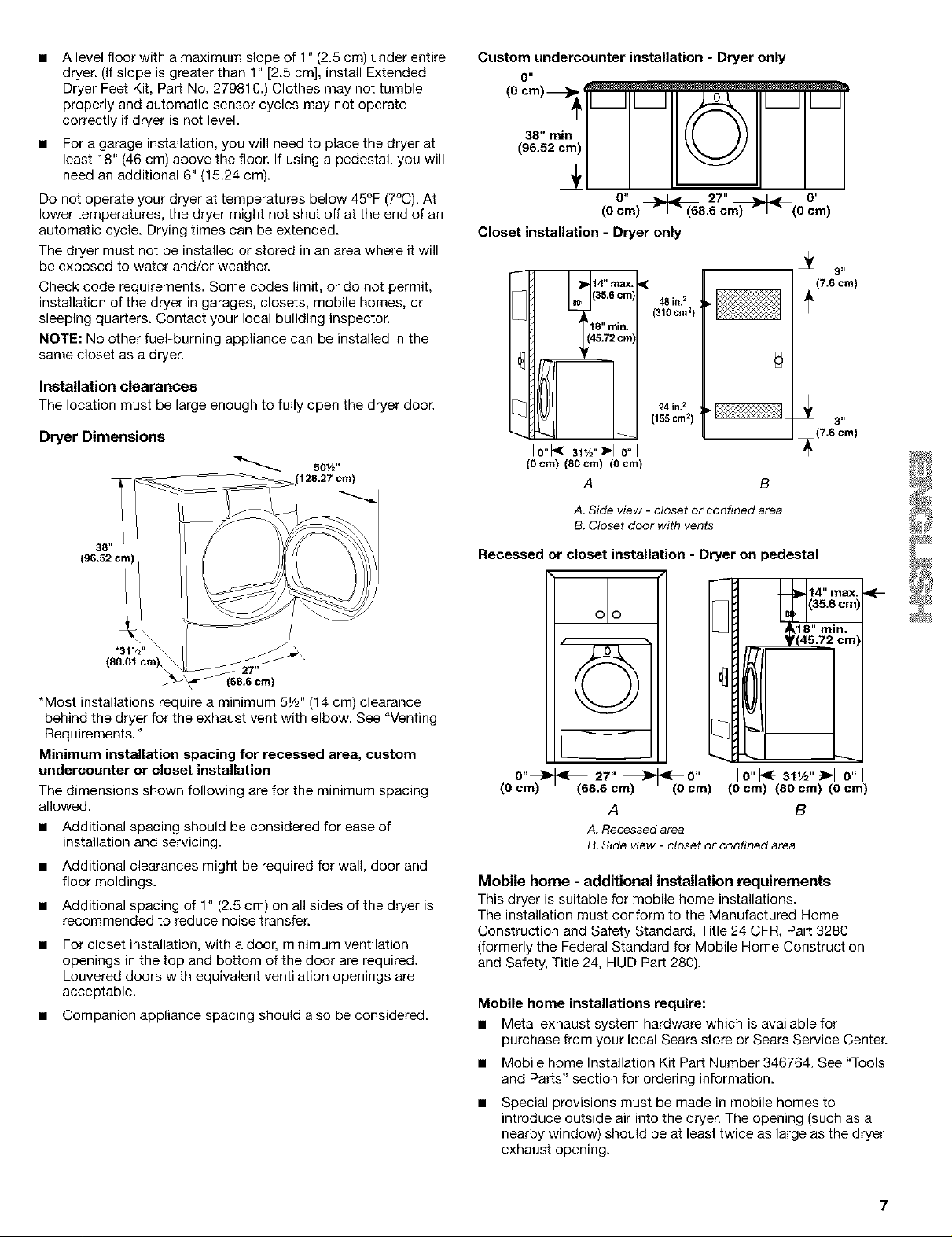
Installation clearances
The location must be large enough to fully open the dryer door.
Dryer Dimensions
501/="
128.27 cm)
Custom undercounter installation - Dryer only
0"
0" 27" 0"
Closet installation - Dryer only
10 cm2)
48 in?
LI(124 ions2)
Io"l< 31,/o"_o"I
(O cm) (80 cm) (O cm)
A B
A. Side view - closet or confined area
B. Closet door with vents
3 _,
(7.6 cm)
3 _,
(7.6 cm)
*Most installations require a minimum 51_''(14 cm) clearance
behind the dryer for the exhaust vent with elbow. See "Venting
Requirements."
Minimum installation spacing for recessed area, custom
undercounter or closet installation
The dimensions shown following are for the minimum spacing
allowed.
• Additional spacing should be considered for ease of
installation and servicing.
• Additional clearances might be required for wall, door and
floor moldings.
• Additional spacing of 1" (2.5 cm) on all sides of the dryer is
recommended to reduce noise transfer.
For closet installation, with a door, minimum ventilation
openings in the top and bottom of the door are required.
Louvered doors with equivalent ventilation openings are
acceptable.
• Companion appliance spacing should also be considered.
Recessed or closet installation - Dryer on pedestal
14" max, _-
olo
v
O"_ q{-_ 27" _O"
(O cm) (68.6 cm) (0 cm)
A B
A, Recessed area
B. Side view - closet or confined area
Mobile home - additional installation requirements
This dryer is suitable for mobile home installations.
The installation must conform to the Manufactured Home
Construction and Safety Standard, Title 24 CFR, Part 3280
(formerly the Federal Standard for Mobile Home Construction
and Safety, Title 24, HUD Part 280).
Mobile home installations require:
• Metal exhaust system hardware which is available for
purchase from your local Sears store or Sears Service Center.
• Mobile home Installation Kit Part Number 346764. See "Tools
and Parts" section for ordering information.
• Special provisions must be made in mobile homes to
introduce outside air into the dryer. The opening (such as a
nearby window) should be at least twice as large as the dryer
exhaust opening.
10"t<- al,/2">-I 0"
(Ocm) (80 crn) (0 cm)
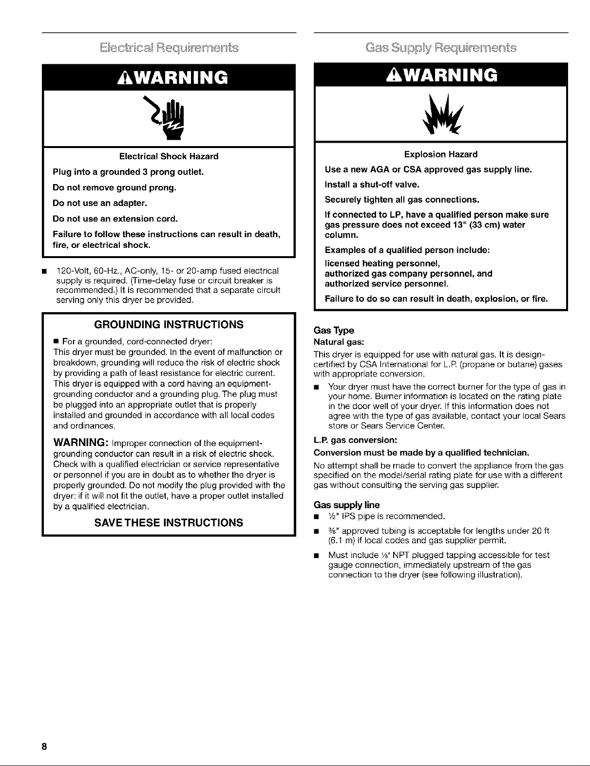
Electrical Shock Hazard
Plug into a grounded 3 prong outlet.
Do not remove ground prong.
Do not use an adapter.
Do not use an extension cord.
Failure to follow these instructions can result in death,
fire, or electrical shock.
n
120-Volt, 60-Hz., AC-only, 15- or 2g-amp fused electrical
supply is required. (Time-delay fuse or circuit breaker is
recommended.) It is recommended that a separate circuit
serving only this dryer be provided.
Explosion Hazard
Use a new AGA or CSA approved gas supply line.
Install a shut-off valve.
Securely tighten all gas connections.
If connected to LP, have a qualified person make sure
gas pressure does not exceed 13" (33 ca) water
column.
Examples of a qualified person include:
licensed heating personnel,
authorized gas company personnel, and
authorized service personnel.
Failure to do so can result in death, explosion, or fire.
GROUNDING INSTRUCTIONS
• For a grounded, cord-connected dryer:
This dryer must be grounded. In the event of malfunction or
breakdown, grounding will reduce the risk of electric shock
by providing a path of least resistance for electric current.
This dryer is equipped with a cord having an equipment-
grounding conductor and a grounding plug. The plug must
be plugged into an appropriate outlet that is properly
installed and grounded in accordance with all local codes
and ordinances.
WARNING: Improper connection of the equipment-
grounding conductor can result in a risk of electric shock.
Check with a qualified electrician or service representative
or personnel if you are in doubt as to whether the dryer is
properly grounded. De not modify the plug provided with the
dryer: if it will not fit the outlet, have a proper outlet installed
by a qualified electrician.
SAVE THESE INSTRUCTIONS
Gas Type
Natural gas:
This dryer is equipped for use with natural gas. It is design-
certified by CSA International for L.R (propane or butane) gases
with appropriate conversion.
n Your dryer must have the correct burner for the type of gas in
your home. Burner information is located on the rating plate
in the door well of your dryer. If this information does not
agree with the type of gas available, contact your local Sears
store or Sears Service Center.
LR gas conversion:
Conversion must be made by a qualified technician.
No attempt shall be made to convert the appliance from the gas
specified on the model/serial rating plate for use with a different
gas without consulting the serving gas supplier.
Gas supply line
n 1/2"IPSpipe is recommended.
n %" approved tubing is acceptable for lengths under 26 ft
(6.1 m) if local codes and gas supplier permit.
n Must include 1/8"NPT plugged tapping accessible for test
gauge connection, immediately upstream of the gas
connection to the dryer (see following illustration).
8
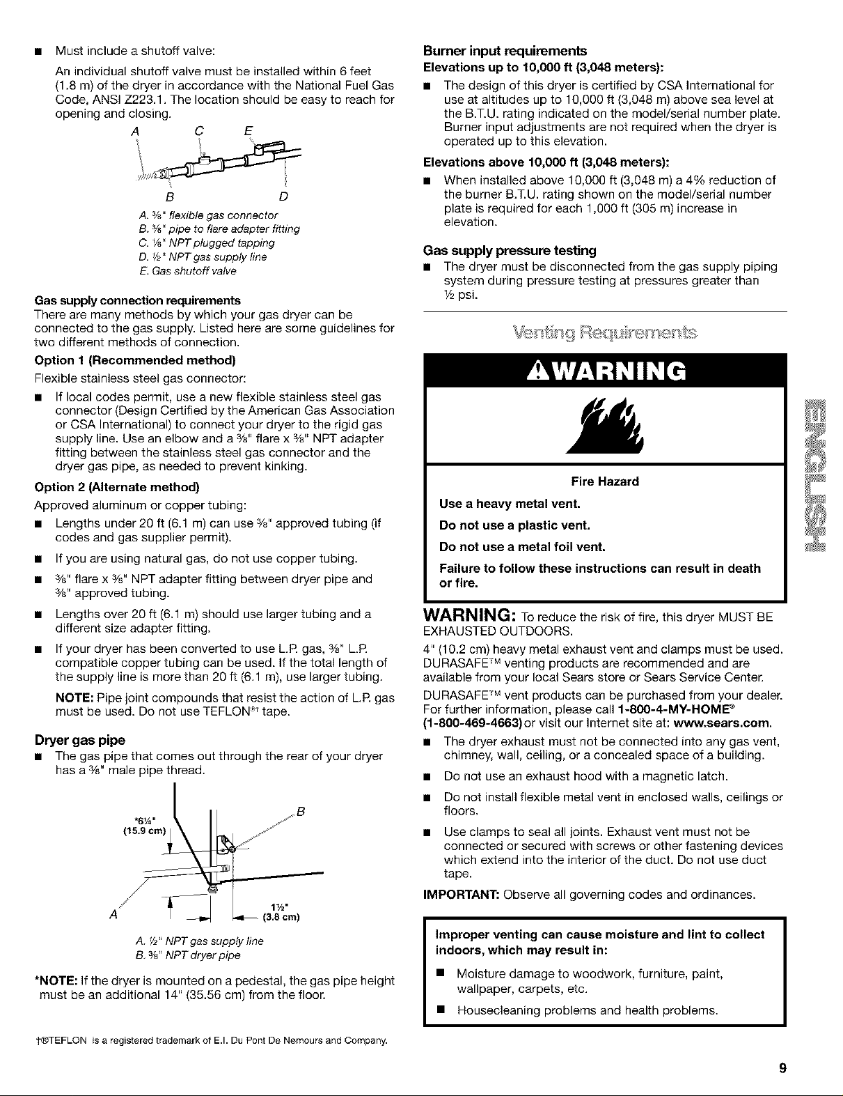
• Must include a shutoff valve:
An individual shutoff valve must be installed within 6 feet
(1.8 m) of the dryer in accordance with the National Fuel Gas
Code, ANSI Z223.1. The location should be easy to reach for
opening and closing.
A C E
B D
A. %" flexiblegas connector
B. 3/8"pipe to flareadapter fitting
C. 1/8"NPTplugged tapping
D. _/2"NPTgas suppty line
E.Gasshutoff valve
Gas supply connection requirements
There are many methods by which your gas dryer can be
connected to the gas supply. Listed here are some guidelines for
two different methods of connection.
Option 1 (Recommended method)
Flexible stainless steel gas connector:
• If local codes permit, use a new flexible stainless steel gas
connector (Design Certified by the American Gas Association
or CSA International) to connect your dryer to the rigid gas
supply line. Use an elbow and a %" flare x %" NPT adapter
fitting between the stainless steel gas connector and the
dryer gas pipe, as needed to prevent kinking.
Option 2 (Alternate method)
Approved aluminum or copper tubing:
• Lengths under 20 ft (6.1 m) can use %" approved tubing (if
codes and gas supplier permit).
• If you are using natural gas, do not use copper tubing.
• %" flare x %" NPT adapter fitting between dryer pipe and
%" approved tubing.
• Lengths over 20 ft (6.1 m) should use larger tubing and a
different size adapter fitting.
• If your dryer has been converted to use L.R gas, %" L.R
compatible copper tubing can be used. If the total length of
the supply line is more than 20 ft (6.1 m), use larger tubing.
NOTE: Pipe joint compounds that resist the action of L.E gas
must be used. Do not use TEFLON ,< tape.
Dryer gas pipe
• The gas pipe that comes out through the rear of your dryer
has a %" male pipe thread.
*6_A,,
(15.9 cm)
/
Burner input requirements
Elevations up to 10,000 ft (3,048 meters):
• The design of this dryer is certified by CSA International for
use at altitudes up to lg,000 ff (3,048 m) above sea level at
the B.T.U. rating indicated on the model/serial number plate.
Burner input adjustments are not required when the dryer is
operated up to this elevation.
Elevations above 10,000 ft (3,048 meters):
• When installed above 10,000 ft (3,048 m) a 4% reduction of
the burner B.T.U. rating shown on the model/serial number
plate is required for each 1,000 ft (305 m) increase in
elevation.
Gas supply pressure testing
• The dryer must be disconnected from the gas supply piping
system during pressure testing at pressures greater than
_/2psi.
Fire Hazard
Use a heavy metal vent.
Do not use a plastic vent.
Do not use a metal foil vent.
Failure to follow these instructions can result in death
or fire.
WARNING: To reduce the risk of fire, this dryer MUST BE
EXHAUSTED OUTDOORS.
4" (10.2 cm) heavy metal exhaust vent and clamps must be used.
DURASAFE TM venting products are recommended and are
available from your local Sears store or Sears Service Center.
DURASAFE TM vent products can be purchased from your dealer.
For further information, please call 1-800-4-MY-HOME ®
(1-800-46g-4663) or visit our Internet site at: www.sears.com.
• The dryer exhaust must not be connected into any gas vent,
chimney, wall, ceiling, or a concealed space of a building.
• Do not use an exhaust hood with a magnetic latch.
• Do not install flexible metal vent in enclosed walls, ceilings or
floors.
• Use clamps to seal all joints. Exhaust vent must not be
connected or secured with screws or other fastening devices
which extend into the interior of the duct. Do not use duct
tape.
IMPORTANT: Observe all governing codes and ordinances.
A. Y2"NPT gas supply line
B.%" NPT dryerpipe
*NOTE: If the dryer is mounted on a pedestal, the gas pipe height
must be an additional 14" (38.86 cm) from the floor.
_TEFLON is a registered trademark of E.I. Du Pont De Nemours and Company.
Improper venting can cause moisture and lint to collect
indoors, which may result in:
• Moisture damage to woodwork, furniture, paint,
wallpaper, carpets, etc.
• Housecleaning problems and health problems.
Use a heavy metal vent. Do not use plastic or metal foil vent.
Rigid metal vent is recommended to prevent crushing and
kinking.
Flexible metal vent must be fully extended and supported when
the dryer is in its final position. Remove excess flexible metal vent
to avoid sagging and kinking that may result in reduced airflow
and poor performance.
An exhaust hood should cap the vent to prevent rodents and
insects from entering the home.
Exhaust hood must be at least 12" (30.5 cm) from the ground or
any object that may be in the path of the exhaust (such as
flowers, rocks or bushes, etc.).
If using an existing vent system, clean lint from the entire length
of the system and make sure exhaust hood is not plugged with
lint. Replace any plastic or metal foil vent with rigid metal or
flexible metal vent.
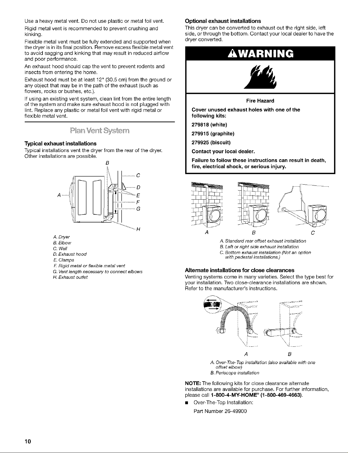
Typical exhaust installations
Typical installations vent the dryer from the rear of the dryer.
Other installations are possible.
B
.....................C
Optional exhaust installations
This dryer can be converted to exhaust out the right side, left
side, or through the bottom. Contact your local dealer to have the
dryer converted.
Fire Hazard
Cover unused exhaust holes with one of the
following kits:
279818 (white)
279915 (graphite)
279925 (biscuit)
Contact your local dealer.
Failure to follow these instructions can result in death,
fire, electrical shock, or serious injury.
............. F
....................G
A Dryer
B. Elbow
C. Waft
D. Exhaust hood
E.Clamps
E Rigid metal or flexible metal vent
G. Vent length necessary to connect elbows
H. Exhaust outlet
A
B C
A.Standard rear offset exhaust installation
B.Left or right side exhaustinstallation
C.Bottom exhaust installation (Not an option
with pedestal installations.)
Alternate installations for close clearances
Venting systems come in many varieties. Select the type best for
your installation. Two close-clearance installations are shown.
Refer to the manufacturer's instructions.
I
is I /l
i i
L L _==
1
//
A B
A. Over-The-Top installation (also available with one
offset elbow)
B. Periscope installation
lO
NOTE: The following kits for close clearance alternate
installations are available for purchase. For further information,
please call f-8OO-4-M¥-HOME e (1-800-469-4663).
• Over-The-Top Installation:
Part Number 26-49900
Periscope Installation (For use with dryer vent to wall vent
mismatch):
Part Number 26-49901 - Less than 5" (12.7 cm) mismatch
Part Number 26-49998 - 5" (12.7 cm) to 18" (45.72 cm)
mismatch
Part Number 26-49904 - 18" (45.72 cm) to 29" (73.66 cm)
mismatch
Part Number 26-49995 - 29" (73.66 cm) to 50" (127 cm)
mismatch
Special provisions for mobile home installations
The exhaust vent must be securely fastened to a noncombustible
portion of the mobile home structure and must not terminate
beneath the mobile home. Terminate the exhaust vent outside.
The angled hood style (shown following) is acceptable.
4"
)_,_( • )
See the exhaust vent length chart that matches your hood
type for the maximum vent lengths you can use.
Exhaust systems longer than specified will:
• Shorten the life of the dryer.
• Reduce performance, resulting in longer drying times and
increased energy usage.
3. Determine the number of elbows you will need.
IMPORTANT: Do not use vent runs longer than specified in
the Vent Length Chart.
The following chart helps you determine your maximum vent
length based on the number of 90 ° turns or elbows you will
need and the type of vent (rigid or flexible metal) and hood
that you will use.
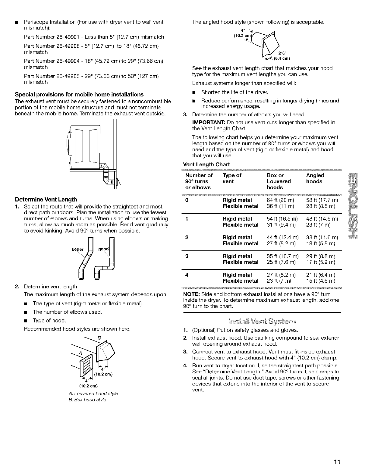
Vent Length Chart
Number of Type of Box or Angled
90° turns vent Louvered hoods
or elbows hoods
Determine Vent Lengfi_
1. Select the route that will provide the straightest and most
direct path outdoors. Plan the installation to use the fewest
number of elbows and turns. When using elbows or making
turns, allow as much room as possible. Bend vent gradually
to avoid kinking. Avoid 99° turns when possible.
better good
2. Determine vent length
The maximum length of the exhaust system depends upon:
• The type of vent (rigid metal or flexible metal).
• The number of elbows used.
• Type of hood.
Recommended hood styles are shown here.
A
(10.2 cm)
A. Louveredhood style
B.Box hood style
O Rigid metal 64 ft (20 m) 58 ft (17.7 m)
Flexible metal 36 ft (11 m) 28 ft (8.5 m)
1 Rigid metal 54 ff (16.5 m) 48 ft (14.6 m)
Flexible metal 31 ft (9.4 m) 23 ft (7 m)
2 Rigid metal 44 ft (13.4 m) 38 ft (11.6 m)
Flexible metal 27 ft (8.2 m) 19 ft (5.8 m)
3 Rigid metal 35 ft (10.7 m) 29 ft (8.8 m)
Flexible metal 25 ft (7.6 m) 17 ft (5.2 m)
4 Rigid metal 27 ft (8.2 m) 21 f1(6.4 m)
Flexible metal 23 ft (7 m) 15 ft (4.6 m)
NOTE: Side and bottom exhaust installations have a 90° turn
inside the dryer. To determine maximum exhaust length, add one
90° turn to the chart.
1. (Optional) Put on safety glasses and gloves.
2. Install exhaust hood. Use caulking compound to seal exterior
wall opening around exhaust hood.
3. Connect vent to exhaust hood. Vent must fit inside exhaust
hood. Secure vent to exhaust hood with 4" (10.2 cm) clamp.
4. Run vent to dryer location. Use the straightest path possible.
See "Determine Vent Length." Avoid 90° turns. Use clamps to
seal all joints. Do not use duct tape. screws or other fastening
devices that extend into the interior of the vent to secure
vent.
11
L gl e s
1. To protect the floor, use a large flat piece of cardboard from
the dryer carton. Place cardboard under the entire back edge
of the dryer. See illustration.
2. Firmly grasp the body of the dryer (not the console panel).
Gently lay the dryer on the cardboard.
3. Examine the leveling legs. Find the diamond marking.
4. Screw the legs into the leg holes by hand. Use a wrench to
finish turning the legs until the diamond marking is no longer
visible.
5. Place a carton corner post under each of the 2 dryer back
corners. Stand the dryer up. Slide the dryer on the corner
posts until it is close to its final location. Leave enough room
to connect the exhaust vent or gas line.
6. Once connection is made and dryer is in final location,
remove corner posts and cardboard.
For mobile home use
Gas dryers must be securely fastened to the floor at the time of
installation.
Check the levelness of the dryer. Check levelness first
side to side, then front to back.
If the dryer is not level, prop up the dryer using a wood block.
Use a wrench to adjust the legs up or down and check again for
levelness.
NOTE: It might be necessary to level the dryer again after it has
been moved into its final position.
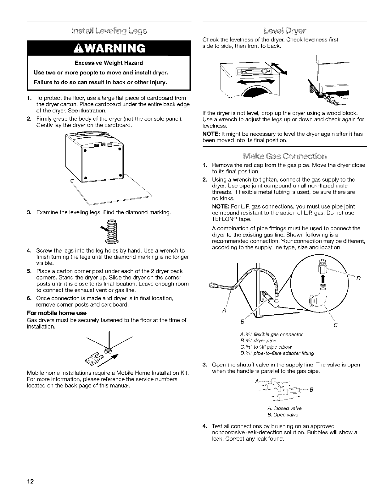
Make Gas Oo s' ecsL
1.
Remove the red cap from the gas pipe. Move the dryer close
to its final position.
2.
Using a wrench to tighten, connect the gas supply to the
dryer. Use pipe joint compound on all non-flared male
threads. If flexible metal tubing is used, be sure there are
no kinks.
NOTE: For L.R gas connections, you must use pipe joint
compound resistant to the action of L.R gas. Do not use
TEFLON _t tape.
A combination of pipe fittings must be used to connect the
dryer to the existing gas line. Shown following is a
recommended connection. Your connection may be different,
according to the supply line type, size and location.
!
B
A. %" flexible gas connector
B. %" dryer pipe
C. %" to %" pipe elbow
D. %" pipe-to-flare adapter fitting
\
C
Mobile home installations require a Mobile Home Installation Kit.
For more information, please reference the service numbers
located on the back page of this manual.
12
3. Open the shutoff valve in the supply line. The valve is open
when the handle is parallel to the gas pipe.
A. Closed valve
B. Open valve
4. Test all connections by brushing on an approved
noncorrosive leak-detection solution. Bubbles will show a
leak. Correct any leak found.
1. Using a 4" (10.2 cm) clamp, connect vent to exhaust outlet in
dryer. If connecting to existing vent, make sure the vent is
clean. The dryer vent must fit over the dryer exhaust outlet
and inside the exhaust hood. Make sure the vent is secured
to exhaust hood with a 4" (10.2 cm) clamp.
2. Move dryer into final position. Do not crush or kink vent.
Make sure dryer is level.
3. (On gas models) Check to be sure there are no kinks in the
flexible gas line.
You can change your door swing from a right-side opening to a
left-side opening, if desired.
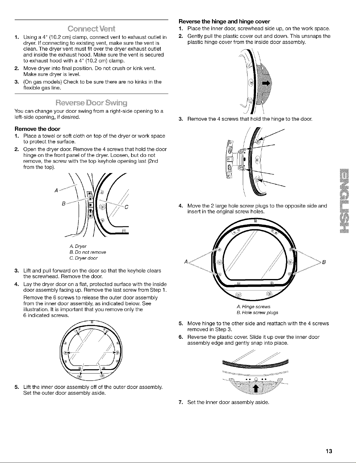
Remove the door
1. Place a towel or soft cloth on top of the dryer or work space
to protect the surface.
2. Open the dryer door. Remove the 4 screws that hold the door
hinge on the front panel of the dryer. Loosen, but do not
remove, the screw with the top keyhole opening last (2nd
from the top).
\
Reverse the hinge and hinge cover
1. Place the inner door, screwhead side up, on the work space.
2. Gently pull the plastic cover out and down. This unsnaps the
plastic hinge cover from the inside door assembly.
3. Remove the 4 screws that hold the hinge to the door.
A, Dryer
B, Do not remove
C. Dryer door
3.
Lift and pull forward on the door so that the keyhole clears
the screwhead. Remove the door.
4.
Lay the dryer door on a flat, protected surface with the inside
door assembly facing up. Remove the last screw from Step 1.
Remove the 6 screws to release the outer door assembly
from the inner door assembly, as indicated below. See
illustration. It is important that you remove only the
6 indicated screws.
4. Move the 2 large hole screw plugs to the opposite side and
insert in the original screw holes.
A. Hinge screws
B. Hole screw plugs
5. Move hinge to the other side and reattach with the 4 screws
removed in Step 3.
6. Reverse the plastic cover. Slide it up over the inner door
assembly edge and gently snap into place.
5.
Lift the inner door assembly off of the outer door assembly.
Set the outer door assembly aside.
7. Set the inner door assembly aside.
13
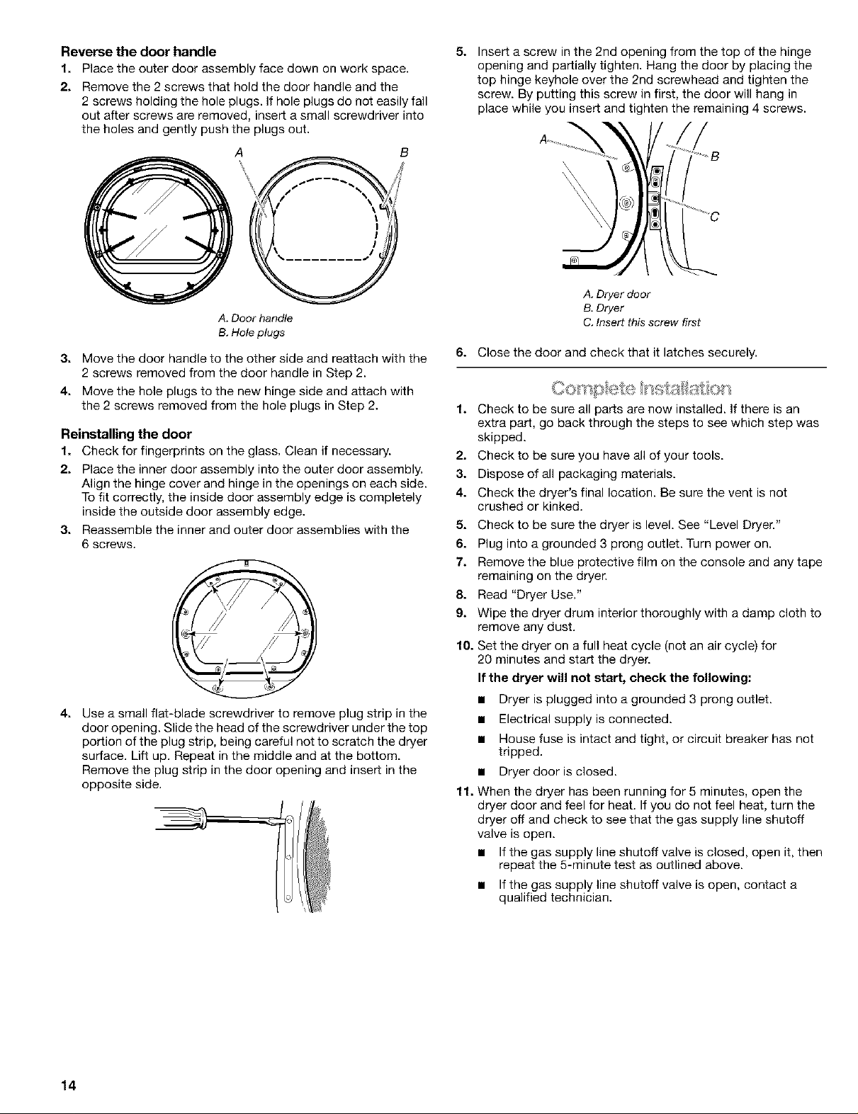
Reverse the door handle
1. Place the outer door assembly face down on work space.
2. Remove the 2 screws that hold the door handle and the
2 screws holding the hole plugs. If hole plugs do not easily fall
out after screws are removed, inser[ a small screwdriver into
the holes and gently push the plugs out.
A
\ /,
A. Door handle
B. Hole plugs
3. Move the door handle to the other side and reattach with the
2 screws removed from the door handle in Step 2.
4. Move the hole plugs to the new hinge side and attach with
the 2 screws removed from the hole plugs in Step 2.
Reinstalling the door
1. Check for fingerprints on the glass. Clean if necessary.
2. Place the inner door assembly into the outer door assembly.
Align the hinge cover and hinge in the openings on each side.
To fit correctly, the inside door assembly edge is completely
inside the outside door assembly edge.
3. Reassemble the inner and outer door assemblies with the
6 screws.
4. Use a small flat-blade screwdriver to remove plug strip in the
door opening. Slide the head of the screwdriver under the top
portion of the plug strip, being careful not to scratch the dryer
surface. Lift up. Repeat in the middle and at the bottom.
Remove the plug strip in the door opening and insert in the
opposite side.
5. Insert a screw inthe 2nd opening from the top of the hinge
opening and partially tighten. Hang the door by placing the
top hinge keyhole over the 2nd screwhead and tighten the
screw. By putting this screw in first, the door will hang in
place while you insert and tighten the remaining 4 screws.
A. Dryer door
B, Dryer
C. Insert this screw first
6. Close the door and check that it latches securely.
1. Check to be sure all parts are now installed. If there is an
extra part, go back through the steps to see which step was
skipped.
2. Check to be sure you have all of your tools.
3. Dispose of all packaging materials.
4. Check the dryer's final location. Be sure the vent is not
crushed or kinked.
5. Check to be sure the dryer is level. See "Level Dryer."
6. Plug into a grounded 3 prong outlet. Turn power on.
7. Remove the blue protective film on the console and any tape
remaining on the dryer.
8. Read "Dryer Use."
9. Wipe the dryer drum interior thoroughly with a damp cloth to
remove any dust.
10. Set the dryer on a full heat cycle (not an air cycle) for
20 minutes and start the dryer.
If the dryer will not start, check the following:
• Dryer is plugged into a grounded 3 prong outlet.
• Electrical supply is connected.
• House fuse is intact and tight, or circuit breaker has not
tripped.
• Dryer door is closed.
11. When the dryer has been running for 5 minutes, open the
dryer door and feel for heat. If you do not feel heat, turn the
dryer off and check to see that the gas supply line shutoff
valve is open.
• If the gas supply line shutoff valve is closed, open it, then
repeat the 5-minute test as outlined above.
• If the gas supply line shutoff valve is open, contact a
qualified technician.
14
DRYER USE
5TA_ CYCLE5
_e o o MOIls NORMAL
_._ D0¢,10 0
W_O _
C0_ct [r_mDo Se:CNDS10U:Ct HEAVY DLJ]Y
J
J
J
AUTO DRY _UAL
AUTODRY
ml._a BULKY/BEDDIN -_
u LO__,mlOt
J
J
Explosion Hazard
Keep flammable materials and vapors, such as
gasoline, away from dryer.
Do not dry anything that has ever had anything
flammable on it (even after washing).
Failure to follow these instructions can result in death,
explosion, or fire.
Fire Hazard
No washer can completely remove oil.
Do not dry anything that has ever had any type of oil on
it (including cooking oils).
Items containing foam, rubber, or plastic must be dried
on a clothesline or by using an Air Cycle.
Failure to follow these instructions can result in death
or fire.
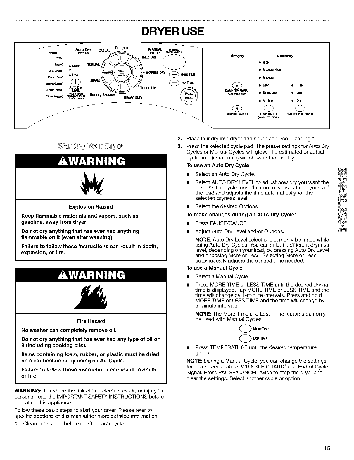
OPIION$ MODIREP_
• HISH
• MEDIUM HI6H
• MEDIUM
• LOW • HIGH
DAMp DRY SIQNAL
O,jjIOOtl_ONL_ • EXI_ALOW • LOW
• AIR DRY • OFF
WR] NIXIE GLIARD TEMPERAI_IRE END of L'_I:IJE._GNAL
2.
Place laundry into dryer and shut door. See "Loading."
3.
Press the selected cycle pad. The preset settings for Auto Dry
Cycles or Manual Cycles will glow. The estimated or actual
cycle time (in minutes) will show in the display.
To use an Auto Dry Cycle
• Select an Auto Dry Cycle.
Select AUTO DRY LEVEL to adjust how dry you want the
load. As the cycle runs, the control senses the dryness of
the load and adjusts the time automatically for the
selected dryness level.
• Select the desired Options.
To make changes during an Auto Dry Cycle:
• Press PAUSE/CANCEL
• Adjust Auto Dry Level and/or Options.
NOTE: Auto Dry Level selections can only be made while
using Auto Dry Cycles. You can select a different dryness
level, depending on your load, by pressing Auto Dry Level
and choosing More or Less. Selecting More or Less
automatically adjusts the sensed time needed.
To
use a Manual Cycle
• Select a Manual Cycle.
Press MORE TIME or LESS TiME until the desired drying
time is displayed. Tap MORE TIME or LESS TIME and the
time will change by 1-minute intervals. Press and hold
MORE TIME or LESS TIME and the time will change by
5-minute intervals.
NOTE: The More Time and Less Time features can only
be used with Manual Cycles.
O ORE]]ME
LESSI]ME
Press TEMPERATURE until the desired temperature
glows.
NOTE: During a Manual Cycle, you can change the settings
for Time, Temperature, WRINKLE GUARD _ and End of Cycle
Signal. Press PAUSE/CANCEL twice to stop the dryer and
clear the settings. Select another cycle or option.
WARNING: To reduce the risk of fire, electric shock, or injury to
persons, read the IMPORTANT SAFETY INSTRUCTIONS before
operating this appliance.
Follow these basic steps to star_ your dryer. Please refer to
specific sections of this manual for more detailed information.
1. Clean lint screen before or after each cycle.
15
 Loading...