How it Works
Log In / Sign Up
0
My Files
0
My Downloads
329070
History
Account Settings
Log Out
Buy Points
How it Works
FAQ
Contact Us
Questions and Suggestions
Users
Kenmore Elite
Loading...
#
2275223
14116673
14116680
153321161
153331000
153332620
153592500
175607930
1102647751K
11023032100
11024082200
11024942300
11024962300
11026922503
11027032600
11027062600
11027062602
11027062604
11027082601
11027082603
11027092600
11027152601
11027152602
11028032700
11028062800
11028081700
11042822200
11042822202
11042922200
11042926202
11043902202
11045081400
11045081401
11045081402
11045801400
11045862401
11045862402
11045962400
11045962401
11045962402
11046742700
11047081600
11047781700
11049962600
11057826600
11060052990
2
11061086000
11064086201
11065064500
11065924400
11065924401
11066944501
11067032600
2
11067062600
11068062800
11068072801
11071062000
11075062500
11076932690
11076972502
11077032600
11078062801
11085081400
11085081401
11085861400
11085862400
11086742700
11087081601
2
11087701700
11087721700
11087872601
11092962100
11092962101
2
11095081400
11095091400
11095861400
11095861401
11096742700
11097081601
11097701700
11097721700
11097872601
11172692910
11610335510
11631150310
11916161210
11916670010
11916676800
12510441710
12521814610
12531150610
14116674800
14117638900
14603358410
14623674310
14629162310
14630207510
14630210510
14648587710
14648589710
Loading...
Loading...
Nothing found
11076932690
Owner’s Manual
80 pgs
2.66 Mb
0
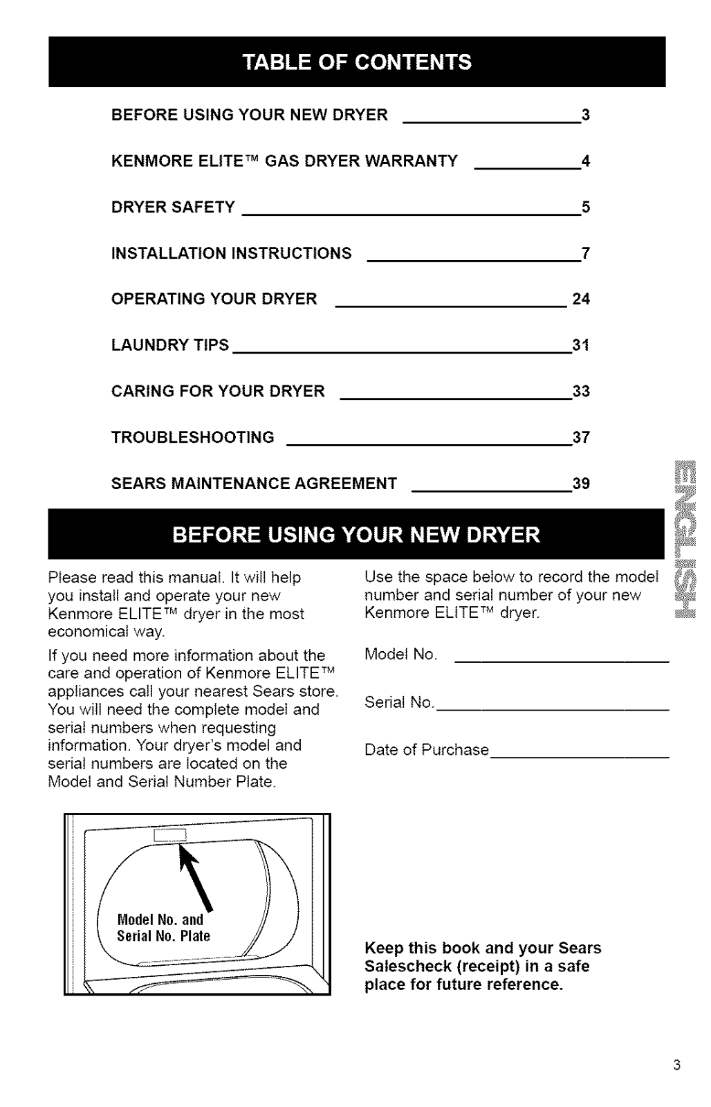
Table of contents
Loading...
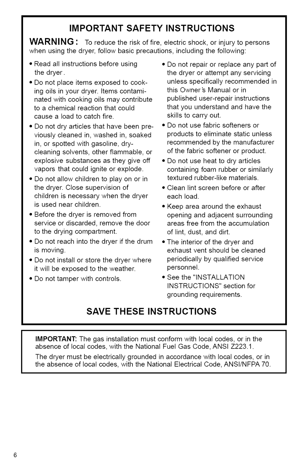
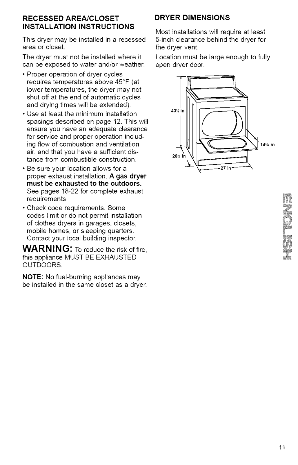
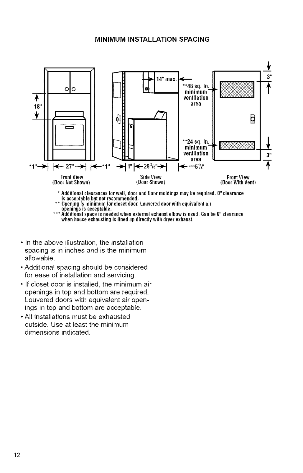
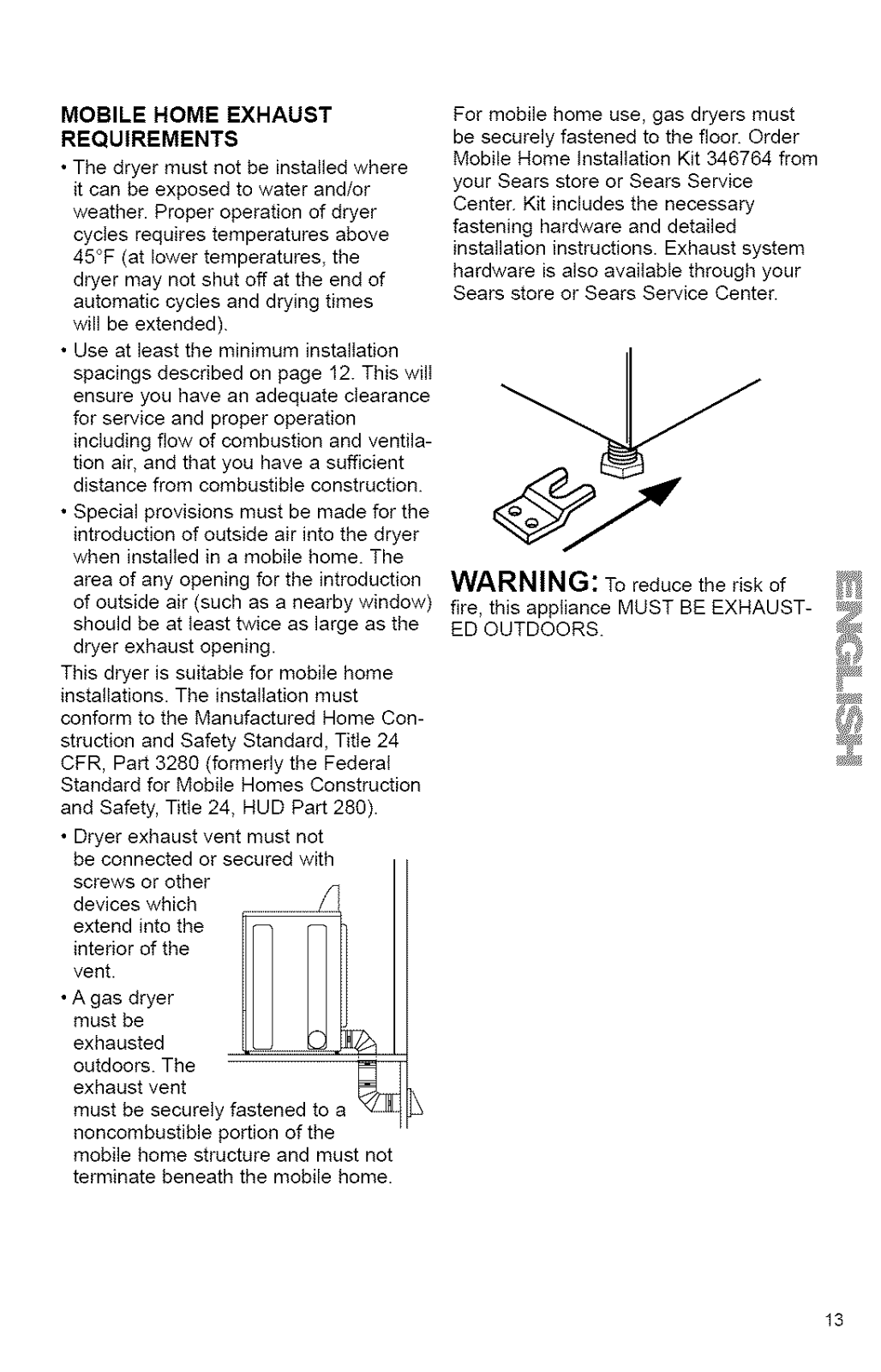
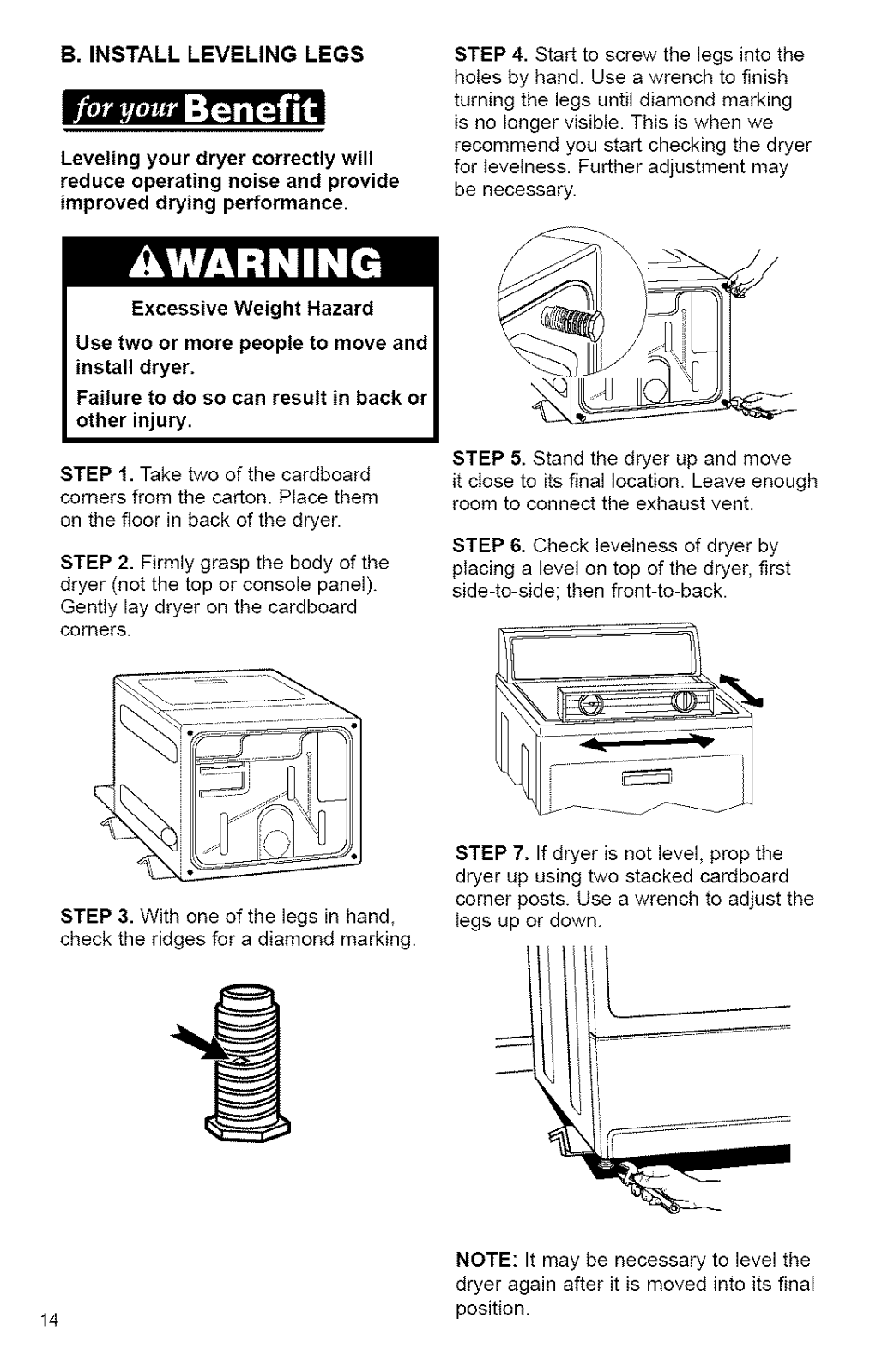
Kenmore Elite 11076932690, 11076934690, 11070942990 Owner’s Manual
...
Kenmore Elite Owner’s Manual
Download
Loading...
+
56
hidden pages
Unhide
You need points to download manuals.
1 point = 1 manual.
You can buy points or you can get point for every manual you upload.
Buy points
Upload your manuals
 Loading...