

Page 1

Page 2
Page 3
Page 4
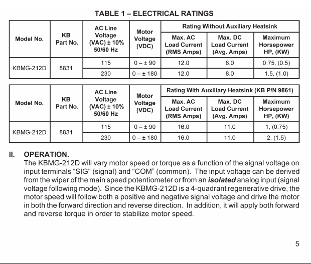
Page 5

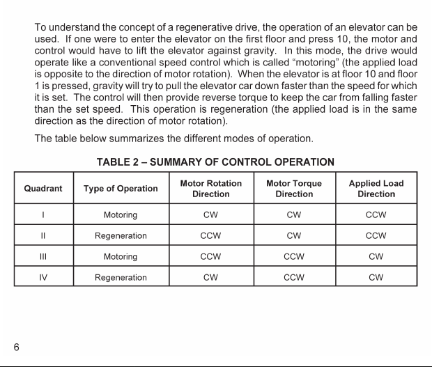
Page 6

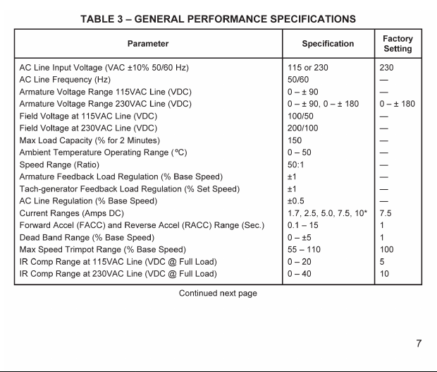
Page 7
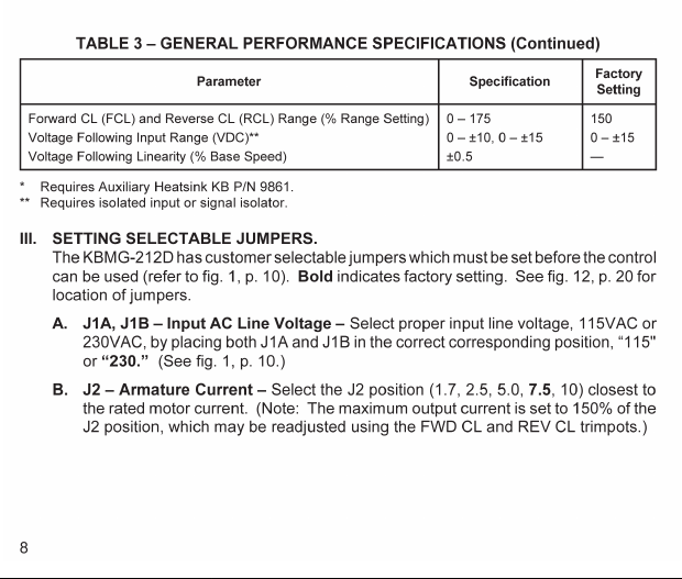
Page 8
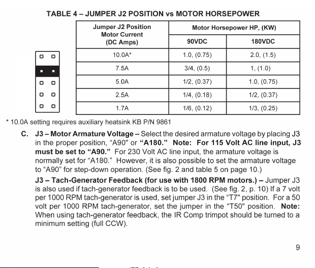
Page 9
Page 10
Page 11
10A
7.5A
5.0A
2.5A
1.7A
Page 12

J1A J1A
115V
230V
J1B
230V
115V
115V
230V
230V
115V
J1B
T50
J3 J3
T7
A180
A90
T50
T7
A180
A90
Page 13

J4 Set
for 15V
Position
10V
15V
J4 Set
for 10V
Position
10V
10V
15V
J5
SPD
TRQ
J5
SPD
TRQ
Page 14

J6 J6
CTS
RTS
CTS
RTS
Page 15

FIG. 6 – SPEED CONTROL MODE
13
HIGHER
SET SPEED
LOWER
SET SPEED
APPLIED LOAD (TORQUE) (%)
CL
SETPOINT
MOTOR SPEED (%)
00101020203030404050506060707080809090100
100
110 120 130 140 150
Page 16

FIG. 7 – TORQUE CONTROL MODE (Linear)
100
90
80
70
60
50
MOTOR SPEED (%)
40
30
20
10
LOWER TORQUE SETTING
0
0102030405060708090 100
S1
S2
HIGHER TORQUE SETTING
APPLIED LOAD (TORQUE) (%)
14
Page 17

Page 18

Page 19

Page 20

Page 21

Page 22

Page 23

FIG. 13 – MECHANICAL SPECIFICAT IONS (INCHES / [mm])
3.625
[92.08]
0.250
[6.35]
1.75
[44.45]
4.300
[109.22]
0.485
[12.32]
0.750
[19.05]
2.500
[63.50]
0.190
[4.83]
3.800
[96.52]
0.950
[24.13]
21
Page 24
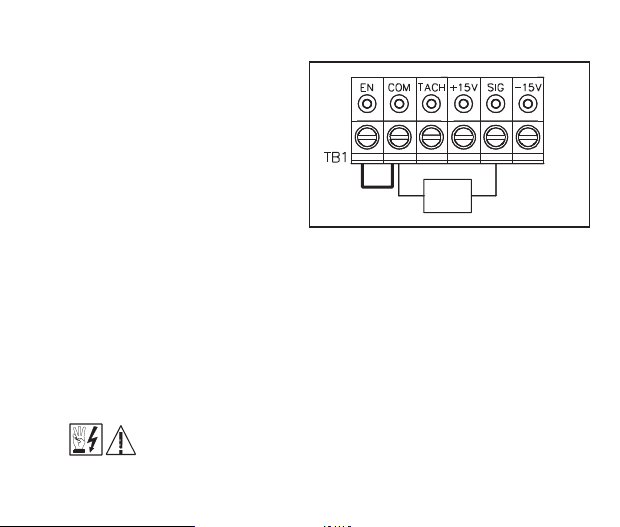
FIG. 14 – VOLTAGE
FOLLOWING CONNECTION
F. Vo ltage Following – An isolated
analog voltage can be used in lieu
of main speed potentiometer.
Connect signal to terminals “SIG"
and “COM.” Note: Te rminal “COM"
is common. A positive signal to
terminal“SIG” will produce a
positive output to motor.
A negative signal to terminal
“SIG" will produce a negative
output. A 0 to ±10VDC is required
to operate control from 0 ± full
output. Note: Jumper J4 must be
in the “10V” position. Note: An isolated signal voltage must be used or
catastrophic failure can result. (A bipolar signal isolator, model SIMG [KB P/N
8832], is available as an option from your distributor. )
G. Enable Start/Stop Circuits – The KBMG-212D contains a 2-wire stop circuit
(Enable), which is used to electronically bring the motor to a “stop.” An isolate
d
single contact closure is required. If an isolated contact is not available, it may be
necessary to use an isolation relay.
*Note: If 2-wire start/stop circuit is not used, a jumper must be wired to EN
and COM or control will not operate.
WARNING! Do not use Start/Stop or Enable functions as a safety
disconnect. Use only an AC line disconnect for that purpose.
22
Jumper*
VDC
0 – ±10V
Page 25

i. Regen to a stop using terminals EN and COM on terminal block TB1 –
When a contact is opened between terminals “EN” and “COM,” with jumper J6
in the “RTS” position, the motor will regeneratively brake to a rapid stop.
Application note (See fig. 15): If controlled regen to stop is required, a contact
can be installed in series with the signal “SIG” connection. T he braking time will
be equal to the REV ACCEL setting when the motor is in the forward direction,
and equal to the FWD ACCEL setting when the motor is in the reverse direction.
Note: J4 must be in the “15V” position. (See fig. 11D, p. 19.)
ii. Coast to a stop using terminals “EN” and “COM” on terminal block TB1 –
If coast to stop operation is required, move jumper J6 to the coast to stop (CTS)
position. When the contact is opened between “EN” and “COM,” the motor will
coast to a stop. See fig. 16.
ENABLE
OPEN TO REGENERATE TO STOP
FIG. 15 – REGENERATE TO STOP
ENABLE
OPEN TO COAST TO STOP
FIG. 16 – COAST TO STOP
*FWD Accel and REV Accel do not affect the stopping time when the enable circuit is opened.
23
J6
CTS
RTS
J6
CTS
RTS
Page 26
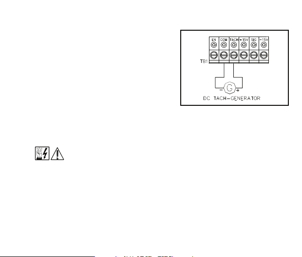
FIG. 17 – TACH-GENERATOR
FEEDBACK
H. Tach-generator Feedback – The KBMG-
212D is factory set for armature feedback,
which provides good load regulation for most
applications. For superior load regulation,
analog tach-generator feedback can be
used.
Wire the tach-generator so that the polarity of
the tach-generator is the same with respect
to the input signal polarity (see fig. 17).
Note: If tach-generator is wired with reverse
polarity, the motor will run at full speed.
Note: Jumper J3 must be set to the proper
position for tach feedback. See sec III, C, p. 9 and fig. 2 on page 10. Note: Check
tach voltage polarity with respect to input signal if polarity does not match reverse
tach leads.
Be sure AC line is disconnected when rewiring tach-generator.
VI.FUSING.
Armature Fuse – It is recommended that the correct size armature fuse be installed,
depending on the rating of the motor and form factor (RMS/AVG current). Fuse type
should be Littelfuse 326 ceramic or Buss ABC, or equivalent. A fuse chart is presented
below which suggests appropriate armature fuse ratings. However, the specific
application may require larger fuse ratings based on ambient temperature, CL set point
and duty cycle of operation (see table 8, p. 25). Fuses may be purchased from your
distributor. Wire fuse in series with armature lead.
24
Page 27

TABLE 8 – ARMATURE FUSE CHART
Motor Horsepower
90VDC 180VDC
Approx. DC
Motor
Current Amps
Fuse Rating
(AC Amps)
1/81/4 1.32
1/61/3 1.72
1/41/2 2.54
1/33/4 3.35
1/215.08
3/417.512
1210.0 20
VII. TRIMPOT ADJUSTMENTS.
The KBMG-212D contains trimpots that have been factory adjusted for most
applications. See specifications for factory settings. (Note: Fig. 12, p. 20, presents the
various trimpots with their location. They are shown in the approximate factory
position.) Some applications may require readjustment of trimpots in order to tailor
control to exact requirements. Readjust trimpots as follows:
25
Page 28

A. Forward Acceleration
FIG. 18 – ACCEL TRIMPOT ADJUSTMENT
(FWD ACCEL) and
Reverse Acceleration
(REV ACCEL) – The FWD
ACCEL trimpot determines
the amount of time it takes
100
(%)
SPEED
the control voltage to reach
full output in the forward
direction. It also determines
the amount of time it takes
0
for the control voltage, in the
reverse direction, to reach
zero output. (FWD ACCEL
is the Reverse Decel.)
The REV ACCEL trimpot
determines the amount of
-100
time it takes the control
voltage to reach full output in the reverse direction and the time it takes for the
control voltage, in the forward direction, to reach zero output. (REV ACCEL is the
Forward Decel.)
The FWD and REV ACCEL trimpots are factory adjusted to approximately 1
second. The acceleration times are adjustable over a range of 0.1 to 15 seconds.
See fig. 18 for graphical representation of ACCEL.
Note: The FWD and REV CL trimpots may override the rapid accel and decel
settings.
26
ACCEL TRIMPOT SETTING
7.5
14.01.0
0.115.0
SECONDS
time
Page 29

FIG. 19 – DEAD BAND TRIMPOT ADJUSTMENT
Note: A 4-quadrant
ACCEL/DECEL accessory
module (KB P/N 8834) is
available as an option.
It provides separate control
of FORWARD acceleration
and deceleration and
REVERSE acceleration
and deceleration.
B. Dead Band Trimpot (DB) –
The DB trimpot sets the
amount of main speed
potentiometer rotation or
analog voltage input
required to initiate control
voltage output. It is factory
adjusted to approximately
25% of rotation.
The DB trimpot also determines the amount of delay that will occur before
regeneration starts. Regeneration occurs when the applied load torque is in the
same direction as the motor rotation.
To readjust the DB to factory setting:
i. Set Main Speed pot to zero speed position.
ii. Set DB trimpot to full CCW position.
27
100
CURVE (a): NO DEAD BAND
CURVE (b): MAX. DEAD BAND
100
-100
-100
(%)
SPEED
a
b
Page 30

iii. Adjust DB trimpot CW until motor hum is eliminated. (See fig. 19, p. 27 for
graphic illustration of the DB trimpot.) Note: If the dead band trimpot is set too
low (CCW direction), the motor may oscillate between forward and reverse.
Adjust dead band trimpot CW until the instability disappears. (Oscillation may
also occur due to RESP and IR COMP trimpot settings. See sec. VII, D & F on
page 29.)
C. Forward Current Limit (FWD CL) and Reverse Current Limit (REV CL)
Trimpots – These trimpots are used to set the maximum amount of DC current that
the motor can draw in both the forward and reverse directions. The amount of DC
current determines the amount of maximum motor torque. They are factory set at
150% of the current established by the jumper J3 setting.
Readjust the CL trimpot as follows:
i. Turn CL trimpot to MIN (CCW) position. Be sure jumper J2 is in the proper
position approximately equal to the motor DC ampere rating.
ii. Wire in a DC ammeter in series with armature lead. Lock shaft of motor.
iii. Apply power. Rotate CL trimpot quickly until desired CL setting is reached
(factory setting is 1.5 times rated motor current). Be sure control is in forward
direction for FWD CL trimpot adjustment and likewise with REV CL.
Warning! To prevent motor damage, do not leave motor shaft locked fo r
more than 2 – 3 seconds.
Caution! Adjusting the CL above 150% of motor rating can cause
overheating and demagnetization of some PM motors. Consult motor
manufacturer.
28
Page 31

Page 32

Page 33

31
Page 34

32
Page 35

33
Page 36

 Loading...