

Page 1

“The Right Control for Your Application.”
12095 NW 39 Street, Coral Springs, FL 33065-2516
KB Electronics, Inc. Telephone: 954-346-4900; Fax: 954-346-3377
6LJQDO,VRODWRU6,0*3DUW1R,QVWDOODWLRQDQG:LULQJ,QVWUXFWLRQV
IRU0RGHO.%0*ZLWK3LHFH)LQJHU6DIH&RYHU
This document is supplied with Model KBMG only.
Warning! Before installing the SIMG onto the KBMG, the AC power must be disconnected.
The following Installation and Wiring instructions are to be used as a supplement to the KBMG Installation and Operating Instructions Manual
(Part No. A40263). Refer to the SIMG Installation and Operating Instructions Manual (Part No. A40269) for specific and external signal
following connections. See Figures 1 - 5, on page 2.
Tools required for installation: small flat blade screwdriver, long nose pliers, cutters.
Notes: 1. To install the SIMG, be sure the Top Panel of the KBMG 2-Piece Finger-Safe Cover (FSC) is not installed. 2. All trimpots and
jumpers, on the KBMG, must be set before installing the SIMG.
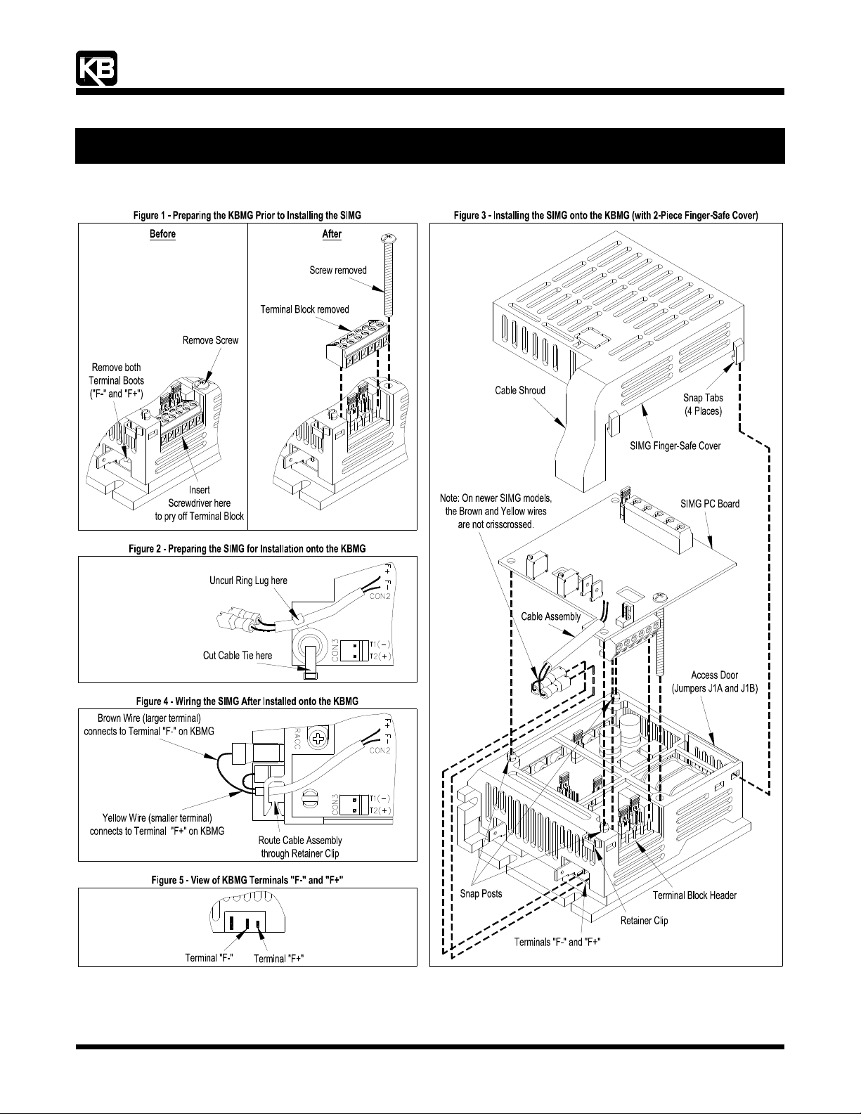
1 Preparing the KBMG Prior to Installing the SIMG - See Figure 1.
1.1 Insert the flat blade screwdriver between the KBMG PC Board and Terminal Block TB1 and gently pry it off. Discard the Terminal
Block.
Note: When prying off the Terminal Block, care should be taken to not scratch circuit traces that are on the PC Board surface.
1.2 Using a flat blade (or Phillips) screwdriver, remove the screw from the KBMG FSC. Retain this screw for use in Section 3.3, below.
1.3 Using long nose pliers, remove and discard the Terminal Boots that are factory installed on Terminals "F-" and "F+" on the KBMG.
2 Preparing the SIMG for Installation onto the KBMG - See Figure 2.
Note: If the SIMG does not contain a Ring Lug and Cable Tie, proceed to paragraph 3 below.
2.1 Using long nose pliers, carefully uncurl the Ring Lug off the Cable Assembly.
2.2 Using cutters, carefully remove the Cable Tie from the SIMG.
2.3 Discard the Ring Lug and Cable Tie.
3 Installing the SIMG onto the KBMG - See Figure 3.
3.1 Align and gently push the Terminal Block on the SIMG onto the Terminal Block Header on the KBMG.
3.2 Align the (3) Holes on the SIMG with the (3) Snap Posts on the KBMG FSC. Gently press the SIMG Board onto the (3) Snap Posts.
Apply pressure at each Snap Post.
3.3 Install the Screw, that was removed in Section 1.2, and gently tighten it to secure the SIMG onto the KBMG FSC. Do not
overtighten.
4 Wiring the SIMG After Installed onto the KBMG - See Figures 4 and 5.
Note: On older SIMG models, the Brown and Yellow Wires must be crisscrossed, as shown in Figure 3. On newer SIMG models, the
Brown and Yellow Wires are not crisscrossed.
4.1 Carefully insert the Cable Assembly through the Retainer Clip on the KBMG FSC.
4.2 Connect the Brown Wire (larger terminal) to Terminal F- on the KBMG.
4.3 Connect the Yellow Wire (smaller terminal) to Terminal F+ on the KBMG.
5 Installing the SIMG Finger-Safe Cover - See Figure 3.
Align the (4) Snap Tabs on the SIMG FSC with the (4) slots on the KBMG FSC. The Cable Shroud must be positioned over the Cable
Assembly (Brown and Yellow Wires). Apply pressure to snap the cover into position.
Note: Be sure that the Cable Assembly is centered in the Retaining Clip so the wires are not damaged by the Cable Shroud.
The SIMG Installation is now complete.
(A40138) - Rev. B00 - 9/1/2004 - Z3031B00 Page 1 of 2
Page 2
“The Right Control for Your Application.”
12095 NW 39 Street, Coral Springs, FL 33065-2516
KB Electronics, Inc. Telephone: 954-346-4900; Fax: 954-346-3377
6LJQDO,VRODWRU6,0*3DUW1R,QVWDOODWLRQDQG:LULQJ,QVWUXFWLRQV
IRU0RGHO.%0*ZLWK3LHFH)LQJHU6DIH&RYHU
(A40138) - Rev. B00 - 9/1/2004 - Z3031B00 Page 2 of 2
Page 3

INSTALLATION AND OPERATING INSTRUCTIONS
™
REGENERATIVE DRIVE
MODEL KBMG-212D
KB Part No. 8831
Variable Speed SCR Control Designed for
Shunt Wound and PM DC Motors
FULL WAVE • 4 QUADRANT
See Safety Warning
on Page 3
The information contained in this manual is
intended to be accurate. However, the
manufacturer retains the right to make changes in
design which may not be included herein.
A COMPLETE LINE OF MOTOR DRIVES
TABLE OF CONTENTS
Section Page
i. Simplified Setup and
Operating Instructions .............. 1
ii. Safety Warning ...................3
I. General Information ................ 4
II. Operation ........................5
III. Setting Selectable Jumpers .......... 8
IV. Mounting ....................... 15
V. Wiring ......................... 15
VI. Fusing ......................... 24
VII. Trimpot Adjustments .............. 25
VIII. Function Indicator Lamps ........... 30
IX. KBMG-212D Accessories .......... 30
X. Limited Warranty ................. 34
TABLES
1. Electrical Ratings .................. 5
2. Summary of Control Operation ....... 6
3. General Performance Specifications . 7,8
4. Jumper J2 Position vs
Motor Horsepower ................. 9
5. Relationship of AC Line Input and Motor
Voltage with J1A, J1B and J3 ....... 10
6. Terminal Block Wiring Information .... 15
7. Field Connections ................ 18
8. Armature Fuse Chart .............. 25
© 1999 KB Electronics, Inc.
FIGURES Page
1. AC Line Voltage Jumper Setting .......10
2. Motor Armature Voltage
Jumper Setting ....................10
3. Jumper J4 Setting ..................11
4. Jumper J5 Setting ..................11
5. Jumper J6 Setting ..................12
6. Speed Control Mode ................13
7. Torque Control Mode ...............14
8. AC Line Connection ................16
9. Armature Connection ...............16
10A. Full Voltage Field ..................17
10B. Half Voltage Field ..................17
11. Main Speed Potentiometer
Connections ......................19
12. Control Layout ....................20
13. Mechanical Specifications ...........21
14. Voltage Following Connection ........22
15. Regenerate to Stop .................23
16. Coast to Stop .....................23
17. Tach-Generator Feedback ...........24
18. Accel Trimpot Adjustment ............26
19. Dead Band Trimpot Adjustment .......27
ii
Page 4

i. KBMG-212D SIMPLIFIED OPERATING INSTRUCTIONS
IMPORTANT – You must read these simplified operating instructions before you proceed.
These instructions are to be used as a reference only and are not intended to replace the
detailed instructions provided herein. You must read the Safety Warning before proceeding.
1. CONNECTIONS.
A. AC Line – Wire AC line voltage to terminals L1 and L2. Be sure jumpers J1A and
J1B are both set to the correct input line voltage 115 or 230 VAC. Connect ground
wire (earth) to green ground screw.
B. Motor.
1. Permanent Magnet (PM Type). Connect motor armature leads to M1(+) and
M2 (–). Be sure jumper J3 is set to the proper position “A90" for 90 volt DC
motors and “A180" for 180 volt DC motors. Note: 180 volt DC motors must be
used with 230 VAC line, 90 volt motors can be used with a 230 VAC or 115 VAC
line.
Note: Motor performance and efficiency, including brush life, can be
adversely affected when using 90 volt motors with a 230 VAC line. Contact
motor manufacturer for derating information.
2. Shunt Wound Motors. Connect motor armature leads as above. Connect full
voltage shunt field leads (90 volt motors with 100 volt fields and 180 volt with
200 volt fields) to F+ and F-. Connect half voltage field leads (90 volt motors
with 50 volt fields and 180 volt motors with 100 volt fields) to F+ and L1.
2. MOTOR CURRENT.
Jumper J2 is factory set for 7.5 amp motors (7.5A). For lower amperage motors, place
J2 in the proper position. If motor amperage is less than 1.7 amps, use the 1.7 amp
position and readjust the IR and CL trimpots according to section VII, C and D on pages
28 and 29. Note: The factory setting for Current Limit is 150% of the nominal current
setting (e.g., if J2 is selected for 5 amps, the actual CL setting will be 7.5 amps). Note:
If the 10.0 amp setting (10.0A) is required, an auxiliary heatsink (KB P/N 9861) must be
used.
3. TRIMPOT SETTINGS.
All trimpots have been factory set in accordance with figure 12, p. 20.
4. ENABLE.
A jumper must be connected between “EN” and “COM” terminals or control will not
operate. (See sec. V, G, page 22.)
Note: For the location of jumpers and trimpots, see fig. 12, control layout, on page 20.
5. SPEED OR TORQUE MODE.
Jumper J5 is factory set for speed control operation (SPD). For torque control, set J5
to the “TRQ” position.
1
2
Page 5

ii. SAFETY WARNING! — PLEASE READ CAREFULLY
This product should be installed and serviced by a qualified technician, electrician
or electrical maintenance person familiar with its operation and the hazards involved.
Proper installation, which includes wiring, mounting in proper enclosure, fusing or other
overcurrent protection and grounding, can reduce the chance of electric shocks, fires or
explosion in this product or products used with this product, such as electric motors,
switches, coils, solenoids or relays. Eye protection must be worn and insulated
adjustment tools must be used when working with control under power. This product is
constructed of materials (plastics, metals, carbon, silicon, etc.) which may be a potential
hazard. Proper shielding, grounding and filtering of this product can reduce the emission
of radio frequency interference (RFI) which may adversely affect sensitive electronic
equipment. If information is required on this product, contact our factory. It is the
responsibility of the equipment manufacturer and individual installer to supply this safety
warning to the ultimate user of this product. (SW effective 11/92)
This control contains electronic Start/Stop and enable circuits that can be used to
start and stop the control. However, these circuits are never to be used as safety
disconnects since they are not fail-safe. Use only the AC line for this purpose.
The input circuits of this control (potentiometer, start/stop, enable) are not isolated
from AC line. Be sure to follow all instructions carefully. Fire and/or electrocution
can result due to improper use of this product.
This product complies with all CE directives pertinent at the time of
manufacture. Contact factory for detailed installation instructions and
Declaration of Conformity. Installation of a CE approved RFI filter (KBRF-200A,
KB P/N 9945C or equivalent) is required. Additional shielded motor cable and/or
AC line cables may be required along with a signal isolator (model SIMG, KB P/N
8832 or equivalent).
I. GENERAL INFORMATION.
The KBMG-212D is a full-wave regenerative control, capable of operating a DC motor
(Permanent Magnet or Shunt) in a bidirectional mode. It provides 4-quadrant operation
which allows forward and reverse torque in both speed directions. The drive offers
excellent controllability, which closely approximates the performance of servo-type
drives. Ratings and specifications are presented in tables 1 and 3. Be sure the drive
is used within these ratings and specifications.
(Note: Regenerative drives normally produce more motor heating than standard
unidirectional SCR speed controls, especially under low speed operation. This
should be taken into consideration when specifying motor rating.)
3
Safety Warning.
4
WARNING! Be sure to follow all instructions carefully. Fire or
electrocution can result due to improper use of this product. Read
Page 6

TABLE 1 – ELECTRICAL RATINGS
Rating Without Auxiliary Heatsink
Max. AC
Load Current
(RMS Amps)
Rating With Auxiliary Heatsink (KB P/N 9861)
Max. AC
Load Current
(RMS Amps)
Max. DC
Load Current
(Avg. Amps)
Max. DC
Load Current
(Avg. Amps)
Maximum
Horsepower
HP, (KW)
Maximum
Horsepower
HP, (KW)
Model No.
KBMG-212D 8831
Model No.
KBMG-212D 8831
KB
Part No.
KB
Part No.
AC Line
Voltage
(VAC) ± 10%
50/60 Hz
115 0 – ± 90 12.0 8.0 0.75, (0.5)
230 0 – ± 180 12.0 8.0 1.5, (1.0)
AC Line
Voltage
(VAC) ± 10%
50/60 Hz
115 0 – ± 90 16.0 11.0 1, (0.75)
230 0 – ± 180 16.0 11.0 2, (1.5)
Motor
Voltage
(VDC)
Motor
Voltage
(VDC)
II. OPERATION.
The KBMG-212D will vary motor speed or torque as a function of the signal voltage on
input terminals “SIG" (signal) and “COM” (common). The input voltage can be derived
from the wiper of the main speed potentiometer or from an isolated analog input (signal
voltage following mode). Since the KBMG-212D is a 4-quadrant regenerative drive, the
motor speed will follow both a positive and negative signal voltage and drive the motor
in both the forward direction and reverse direction. In addition, it will apply both forward
and reverse torque in order to stabilize motor speed.
To understand the concept of a regenerative drive, the operation of an elevator can be
used. If one were to enter the elevator on the first floor and press 10, the motor and
control would have to lift the elevator against gravity. In this mode, the drive would
operate like a conventional speed control which is called “motoring” (the applied load
is opposite to the direction of motor rotation). When the elevator is at floor 10 and floor
1 is pressed, gravity will try to pull the elevator car down faster than the speed for which
it is set. The control will then provide reverse torque to keep the car from falling faster
than the set speed. This operation is regeneration (the applied load is in the same
direction as the direction of motor rotation).
The table below summarizes the different modes of operation.
TABLE 2 – SUMMARY OF CONTROL OPERATION
Quadrant Type of Operation
I Motoring CW CW CCW
II Regeneration CCW CW CCW
Motor Rotation
Direction
Motor Torque
Direction
Applied Load
Direction
5
III Motoring CCW CCW CW
IV Regeneration CW CCW CW
6
Page 7

TABLE 3 – GENERAL PERFORMANCE SPECIFICATIONS
Parameter Specification
AC Line Input Voltage (VAC ±10% 50/60 Hz)
AC Line Frequency (Hz)
Armature Voltage Range 115VAC Line (VDC)
Armature Voltage Range 230VAC Line (VDC)
Field Voltage at 115VAC Line (VDC)
Field Voltage at 230VAC Line (VDC)
Max Load Capacity (% for 2 Minutes)
Ambient Temperature Operating Range (ºC)
Speed Range (Ratio)
Armature Feedback Load Regulation (% Base Speed)
Tach-generator Feedback Load Regulation (% Set Speed)
AC Line Regulation (% Base Speed)
Current Ranges (Amps DC)
Forward Accel (FACC) and Reverse Accel (RACC) Range (Sec.)
Dead Band Range (% Base Speed)
Max Speed Trimpot Range (% Base Speed)
IR Comp Range at 115VAC Line (VDC @ Full Load)
IR Comp Range at 230VAC Line (VDC @ Full Load)
Continued next page
115 or 230
50/60
0 – ± 90
0 – ± 90, 0 – ± 180
100/50
200/100
150
0 – 50
50:1
±1
±1
±0.5
1.7, 2.5, 5.0, 7.5, 10*
0.1 – 15
0 – ±5
55 – 110
0 – 20
0 – 40
Factory
Setting
230
—
—
0 – ± 180
—
—
—
—
—
—
—
—
7.5
1
1
100
5
10
TABLE 3 – GENERAL PERFORMANCE SPECIFICATIONS (Continued)
Parameter Specification
Forward CL (FCL) and Reverse CL (RCL) Range (% Range Setting)
Voltage Following Input Range (VDC)**
Voltage Following Linearity (% Base Speed)
* Requires Auxiliary Heatsink KB P/N 9861.
** Requires isolated input or signal isolator.
0 – 175
0 – ±10, 0 – ±15
±0.5
III. SETTING SELECTABLE JUMPERS.
The KBMG-212D has customer selectable jumpers which must be set before the control
can be used (refer to fig. 1, p. 10). Bold indicates factory setting. See fig. 12, p. 20 for
location of jumpers.
A. J1A, J1B – Input AC Line Voltage – Select proper input line voltage, 115VAC or
230VAC, by placing both J1A and J1B in the correct corresponding position, “115"
or “230.” (See fig. 1, p. 10.)
B. J2 – Armature Current – Select the J2 position (1.7, 2.5, 5.0, 7.5, 10) closest to
the rated motor current. (Note: The maximum output current is set to 150% of the
J2 position, which may be readjusted using the FWD CL and REV CL trimpots.)
7
Factory
Setting
150
0 – ±15
—
8
Page 8

TABLE 4 – JUMPER J2 POSITION vs MOTOR HORSEPOWER
Jumper J2 Position
Motor Current
(DC Amps)
10.0A* 1.0, (0.75) 2.0, (1.5)
7.5A 3/4, (0.5) 1, (1.0)
5.0A 1/2, (0.37) 1.0, (0.75)
2.5A 1/4, (0.18) 1/2, (0.37)
1.7A 1/6, (0.12) 1/3, (0.25)
* 10.0A setting requires auxiliary heatsink KB P/N 9861
Motor Horsepower HP, (KW)
90VDC 180VDC
C. J3 – Motor Armature Voltage – Select the desired armature voltage by placing J4
in the proper position, “A90" or “A180.” Note: For 115 volt AC line input, J3
must be set to “A90.” For 230 input, the armature voltage is normally set for
“A180.” However, it is also possible to set the armature voltage to “A90" for stepdown operation. (See fig. 2 and table 5 on page 10.)
J3 – Tach-Generator Feedback (for use with 1800 RPM motors.) – Jumper J3
is also used if tach-generator feedback is to be used. (See fig. 2, p. 10) If a 7 volt
per 1000 RPM tach-generator is used, set jumper J4 in the “T7" position. For a 50
volt per 1000 RPM tach-generator, set the jumper in the “T50" position. Note:
When using tach-generator feedback, the IR Comp trimpot should be turned to a
minimum setting (full CCW).
FIG. 1 – AC LINE VOLTAGE
JUMPER SETTING (J1A, J1B)
115VAC 230VAC
FIG. 2 – MOTOR ARMATURE VOLTAGE
JUMPER SETTING (J3)
90VDC 180VDC
TABLE 5 – RELATIONSHIP of AC LINE INPUT AND MOTOR
VOLTAGE with J1A, J1B and J3 JUMPER POSITION
AC LINE INPUT VOLTAGE J1A, J1B POSITION J3 POSITION MOTOR VOLTAGE
115 115 90 90
9
230 230 180 180
230 230 90* 90*
*A 90VDC motor can be used with a 230VAC line (J3 set in “A90" position). However, speed range may
be reduced and motor derating may be required.
10
Page 9

D. J4 – Analog Input Voltage –
Jumper J4 is set to the “15V”
position for potentiometer
FIG. 3 – JUMPER J4 SETTING
Potentiometer Operation Signal Following
operation. If the control is to
be operated from an isolated
0 – ±10VDC signal (see sec. V,
F, p. 22.), set J4 to the “10V”
position.
E. J5 – Control Mode (Speed or
Torque).
i. Speed (SPD) Mode – (Note:
Factory setting of J5 is
Speed mode.) In the speed
FIG. 4 – JUMPER J5 SETTING
Speed Mode Torque Mode
control mode (J5 set to
SPD), the KBMG-212D will
provide variable speed
control. The motor speed
will be in direct proportion to
the input signal. Both forward and reverse torque are used to stabilize motor
speed. (See fig. 6, p. 13.)
ii. Torque (TRQ) Mode – In the torque control mode (J5 set to TRQ), the
KBMG-212D will vary the maximum motor torque as a function of the voltage
input to terminals “SIG” (signal) and “COM” (common). This voltage can be
derived from the wiper of the main potentiometer or from an isolated analog
input (signal voltage following).
If the motor torque is greater than the load torque, the motor will rotate. If no
load is applied to the motor, the motor will rotate at a speed proportional to the
torque setting as set by the main potentiometer (see fig. 7, p. 14). By using the
ACCEL and DECEL trimpots, the application of torque can be made more
gradual or less gradual as required by the application. A maximum torque can
be established using the current selector jumper, J2, which can be further
modified by using the FWD and REV CL trimpots.
F. J6 – Coast to Stop (CTS),
Regenerate to Stop (RTS) –
This function operates in
FIG. 5 – JUMPER J6 SETTING
Coast to Stop Regenerate to Stop
conjunction with the Enable
circuit, which is used to start
and stop the control
electronically. If the circuit
connecting terminals “EN” and
“COM” on terminal block TB1
are opened, the control will cause the motor to stop. When jumper J6 is in the
factory position (RTS), the motor will regenerate to a stop.
If J6 is changed to the coast to stop (CTS) position, the motor will coast to a stop
when the “EN” - “COM” circuit is opened.
11
12
Note: Control will not run unless a jumper or closed contact is connected
between the “EN” and “COM” terminals.
Page 10

FIG. 6 – SPEED CONTROL MODE
FIG. 7 – TORQUE CONTROL MODE (Linear)
13
14
Page 11

IV. MOUNTING.
Mount the KBMG-212D on a flat surface in an atmosphere free of moisture, metal chips,
and corrosion. See Mechanical Specifications, fig. 13, p. 21. A 5K ohm remote speed
potentiometer is provided with each control. Install potentiometer using hardware
provided. Be sure to install insulating disk between potentiometer and inside of front
panel.
Enclosure – When mounting the KBMG-212D in an enclosure, it must be large enough
to allow the proper heat dissipation. A 12"12"12" enclosure is suitable when the
control is not mounted on an auxiliary heatsink. A 12"12"24" enclosure is
appropriate at full rating (11.0 amps) when the control is mounted on an auxiliary
heatsink KB P/N 9861.
V. WIRING. Warning! Read Safety Warning before attempting to use this
control.
Warning! To avoid erratic operation do not bundle AC line and motor wires with
potentiometer, voltage following, enable, inhibit or other signal wiring. Use
shielded cables on all signal wiring over 12" (30 cm) – Do not ground shield.
TABLE 6 – TERMINAL BLOCK WIRING INFORMATION
Terminal Block
Designation
TB1 Logic Conections 22 14 3.5
Connection
Designation
Wire control in accordance with National Electrical
Supply Wire Gauge
Minimum Maximum
FIG. 8 – AC LINE CONNECTION
Code requirements and other local codes that
apply. A “normal blo” 20 amp fuse or circuit
breaker should be used on each AC line conductor
that is not at ground potential (do not fuse neutral or
grounded conductors). (See section VI, p. 24 for
fuse information.) Wire control in accordance with
connection diagrams (see figures 8, 9, 10A, 10B, 11
and 14 on pages 16, 17, 19 and 22). A separate AC line
switch or contactor must be wired as a disconnect switch so
that contacts open each ungrounded conductor of the control.
See table 6 for terminal block wiring information.
A. AC Line – Connect AC Line to
FIG. 9 – ARMATURE CONNECTION
terminals L1 and L2. (Be sure
jumpers J1A and J1B are set to
match the AC line voltage used.)
(See table 5, p. 10.)
Maximum
Tightening
Torque (in-lbs)
15
B. Ground – Be sure to ground (earth)
control via green screw located
on chassis.
Do not ground any other terminals.
C. Motor Armature – Connect motor armature to terminals M1 (+) and M2 (–). (Be
sure jumper J3 is set to match motor voltage.) (See table 5, p. 10.)
16
Page 12

D. Field – For Shunt Wound motors only.
Do not use F+ and F– terminals for any other motor
type. Connect motor shunt field to terminals F+ and
F– for 90VDC motors with 100VDC fields and 180VDC
motors with 200VDC fields. For motors with half
voltage fields, 90VDC motors with 50VDC fields and
180VDC motors with 100VDC fields, connect field to
terminals F+ and L1. See table 7, p. 18 for summary
of field connections.
CAUTION – Shunt-Wound motors may be damaged due to
overheating if field remains powered without motor rotating
for an extended period of time.
FIG. 10B – HALF VOLTAGE FIELD
FIG. 10A – FULL
VOLTAGE FIELD
TABLE 7 – FIELD CONNECTIONS (Shunt Wound Motors Only)
AC Line Voltage
(VAC)
115 90 100 F+, F–
115 90 50 F+, L1
230 180 200 F+, F–
230 180 100 F+, L1
230 90* 100 F+, L1
*Step Down operation (see sec. III C, p. 9).
Motor Voltage
Field Voltage
(VDC)
Field Connection
E. Main Speed Potentiometer – The main speed potentiometer can be connected in
several ways using terminals “COM,” “+15,” “SIG” and “–15.” A 5K ohm
potentiometer is supplied with control. (A 10K potentiometer can also be used.)
(Warning! Terminals “COM,” “+15,” “SIG” and “–15" are not isolated
from AC line.) Note: Jumper J4 must be in the “15V” position.
i. Unidirectional operation only – Connect potentiometer to terminals “COM,”
“+15,” “SIG" for forward direction. To operate in reverse direction, connect to
“COM,” “SIG,” and “–15.” See fig. 11, p. 19.
17
18
ii. Bidirectional operation only – Connect to terminals “COM,” “+15,” “SIG,” and
“–15" when using reversing contacts. To operate with a potentiometer, connect
to “+15," “SIG,” and “–15." See fig. 11.
Page 13

FIG. 11 – MAIN SPEED POTENTIOMETER CONNECTIONS
A) Forward B) Reverse
C) Bidirectional with Reversing Contact D) Bidirectional with Speed Pot
*Note: A jumper must be wired to EN and
COM in order for control to operate.
FIG. 12 – CONTROL LAYOUT
(Illustrates Factory Setting of Jumpers and Approximate Trimpot Settings)
19
Notch denotes
position.
TRIMPOT
20
Page 14

FIG. 13 – MECHANICAL SPECIFICATIONS (INCHES / [mm])
21
F. Voltage Following – An isolated
analog voltage can be used in lieu
of main speed potentiometer.
Connect signal to terminals “SIG"
and “COM.” Note: Terminal “COM"
is common. A positive signal to
terminal “SIG” will produce a
positive output to motor.
A negative signal to terminal
“SIG" will produce a negative
output. A 0 to ±10VDC is required
to operate control from 0 ± full
output. Note: Jumper J4 must be
in the “10V” position. Note: An isolated signal voltage must be used or
catastrophic failure can result. (A bipolar signal isolator, model SIMG [KB P/N
8832], is available as an option from your distributor.)
G. Enable Start/Stop Circuits – The KBMG-212D contains a 2-wire stop circuit
(Enable), which is used to electronically bring the motor to a “stop.” An isolated
single contact closure is required. If an isolated contact is not available, it may be
necessary to use an isolation relay.
*Note: If 2-wire start/stop circuit is not used, a jumper must be wired to EN
and COM or control will not operate.
FIG. 14 – VOLTAGE
FOLLOWING CONNECTION
22
WARNING! Do not use Start/Stop or Enable functions as a safety
disconnect. Use only an AC line disconnect for that purpose.
Page 15

i. Regen to a stop using terminals EN and COM on terminal block TB1 –
When a contact is opened between terminals “EN” and “COM,” with jumper J6
in the “RTS” position, the motor will regeneratively brake to a rapid stop.
Application note (See fig. 15): If controlled regen to stop is required, a contact
can be installed in series with the signal “SIG” connection. The braking time will
be equal to the REV ACCEL setting when the motor is in the forward direction,
and equal to the FWD ACCEL setting when the motor is in the reverse direction.
Note: J4 must be in the “15V” position. (See fig. 11D, p. 19.)
ii. Coast to a stop using terminals “EN” and “COM” on terminal block TB1 –
If coast to stop operation is required, move jumper J6 to the coast to stop (CTS)
position. When the contact is opened between “EN” and “COM,” the motor will
coast to a stop. See fig. 16.
FIG. 15 – REGENERATE TO STOP
ENABLE
OPEN TO REGENERATE TO STOP
*FWD Accel and REV Accel do not affect the stopping time when the enable circuit is opened.
H. Tach-generator Feedback – The KBMG-
212D is factory set for armature feedback,
FIG. 16 – COAST TO STOP
ENABLE
OPEN TO COAST TO STOP
FIG. 17 – TACH-GENERATOR
FEEDBACK
which provides good load regulation for most
applications. For superior load regulation,
analog tach-generator feedback can be
used.
23
Wire the tach-generator so that the polarity of
the tach-generator is the same with respect
to the input signal polarity (see fig. 17).
Note: If tach-generator is wired with reverse
polarity, the motor will run at full speed.
Note: Jumper J3 must be set to the proper
position for tach feedback. See sec III, C, p. 9 and fig. 2 on page 10. Note: Check
tach voltage polarity with respect to input signal if polarity does not match reverse
tach leads.
Be sure AC line is disconnected when rewiring tach-generator.
VI. FUSING.
Armature Fuse – It is recommended that the correct size armature fuse be installed,
depending on the rating of the motor and form factor (RMS/AVG current). Fuse type
should be Littelfuse 326 ceramic or Buss ABC, or equivalent. A fuse chart is presented
below which suggests appropriate armature fuse ratings. However, the specific
application may require larger fuse ratings based on ambient temperature, CL set point
and duty cycle of operation (see table 8, p. 25). Fuses may be purchased from your
distributor. Wire fuse in series with armature lead.
24
Page 16

TABLE 8 – ARMATURE FUSE CHART
Motor Horsepower
90VDC 180VDC
Approx. DC
Motor
Current Amps
Fuse Rating
(AC Amps)
1/8 1/4 1.3 2
1/6 1/3 1.7 2
1/4 1/2 2.5 4
1/3 3/4 3.3 5
1/2 1 5.0 8
3/4 1 7.5 12
1 2 10.0 20
VII. TRIMPOT ADJUSTMENTS.
The KBMG-212D contains trimpots that have been factory adjusted for most
applications. See specifications for factory settings. (Note: Fig. 12, p. 20, presents the
various trimpots with their location. They are shown in the approximate factory
position.) Some applications may require readjustment of trimpots in order to tailor
control to exact requirements. Readjust trimpots as follows:
A. Forward Acceleration
(FWD ACCEL) and
Reverse Acceleration
FIG. 18 – ACCEL TRIMPOT ADJUSTMENT
ACCEL TRIMPOT SETTING
7.5
(REV ACCEL) – The FWD
ACCEL trimpot determines
the amount of time it takes
the control voltage to reach
full output in the forward
0.1 15.0
SECONDS
direction. It also determines
the amount of time it takes
for the control voltage, in the
reverse direction, to reach
zero output. (FWD ACCEL
is the Reverse Decel.)
The REV ACCEL trimpot
determines the amount of
time it takes the control
voltage to reach full output in the reverse direction and the time it takes for the
control voltage, in the forward direction, to reach zero output. (REV ACCEL is the
Forward Decel.)
The FWD and REV ACCEL trimpots are factory adjusted to approximately 1
second. The acceleration times are adjustable over a range of 0.1 to 15 seconds.
See fig. 18 for graphical representation of ACCEL.
25
14.01.0
26
Note: The FWD and REV CL trimpots may override the rapid accel and decel
settings.
Page 17

Note: A 4-quadrant
ACCEL/DECEL accessory
ADJUSTMENT
FIG. 19 – DEAD BAND TRIMPOT
module (KB P/N 8834) is
available as an option.
It provides separate control
of FORWARD acceleration
and deceleration and
REVERSE acceleration
and deceleration.
B. Dead Band Trimpot (DB) –
The DB trimpot sets the
amount of main speed
potentiometer rotation or
analog voltage input
required to initiate control
voltage output. It is factory
adjusted to approximately
25% of rotation.
The DB trimpot also determines the amount of delay that will occur before
regeneration starts. Regeneration occurs when the applied load torque is in the
same direction as the motor rotation.
To readjust the DB to factory setting:
i. Set Main Speed pot to zero speed position.
ii. Set DB trimpot to full CCW position.
27
iii. Adjust DB trimpot CW until motor hum is eliminated. (See fig. 19, p. 27 for
graphic illustration of the DB trimpot.) Note: If the dead band trimpot is set too
low (CCW direction), the motor may oscillate between forward and reverse.
Adjust dead band trimpot CW until the instability disappears. (Oscillation may
also occur due to RESP and IR COMP trimpot settings. See sec. VII, D & F on
page 29.)
C. Forward Current Limit (FWD CL) and Reverse Current Limit (REV CL)
Trimpots – These trimpots are used to set the maximum amount of DC current that
the motor can draw in both the forward and reverse directions. The amount of DC
current determines the amount of maximum motor torque. They are factory set at
150% of the current established by the jumper J2 setting.
Readjust the CL trimpot as follows:
i. Turn CL trimpot to MIN (CCW) position. Be sure jumper J3 is in the proper
position approximately equal to the motor DC ampere rating.
ii. Wire in a DC ammeter in series with armature lead. Lock shaft of motor.
iii. Apply power. Rotate CL trimpot quickly until desired CL setting is reached
(factory setting is 1.5 times rated motor current). Be sure control is in forward
direction for FWD CL trimpot adjustment and likewise with REV CL.
Warning! To prevent motor damage, do not leave motor shaft locked for
more than 2 – 3 seconds.
Caution! Adjusting the CL above 150% of motor rating can cause
overheating and demagnetization of some PM motors. Consult motor
manufacturer.
28
Page 18

D. IR Compensation (IR Comp) – The IR Comp is used to stabilize motor speed
under varying loads. Readjust the IR Comp trimpot as follows:
i. Initially set trimpot to factory position (approximately 10 o’clock).
ii. Run motor at approximately 30 – 50% of rated speed under no load and
measure actual speed.
iii. Load motor to rated current. Rotate IR Comp trimpot so that loaded speed is the
same as the unloaded speed measured in the previous step.
Control is now compensated so that minimal speed change will occur over a
wide range of motor load. Note: Excessive IR Comp will cause unstable
(oscillatory) operation.
E. Maximum Speed (MAX) – The MAX trimpot is used to set the maximum output
voltage of the control which, in turn, sets the maximum speed of the motor.
Adjust the MAX trimpot as follows:
i. Rotate Main Speed potentiometer to full speed (CW).
ii. Adjust MAX trimpot to desired maximum motor speed.
Note: Do not exceed maximum rated RPM of motor since unstable operation
may result.
F. Response Trimpot (RESP) – This trimpot determines the dynamic response of the
control. The factory setting is approximately 50% of full rotation. The setting may
be increased if a faster response is required. Note: If response is set too fast,
unstable operation may result.
VIII. FUNCTION INDICATOR LAMPS.
A. Power On (PWR ON) – Indicates that the drive is energized with the AC line.
B. Overload (OL) – Indicates the control has reached the current limit set point which
has been established by the position of jumper J2 and the FWD CL and REV CL
trimpot settings. In transient load applications, it is normal for this light to blink.
IX. KBMG-212D ACCESSORIES
• Model SIMG Bipolar Signal Isolator (P/N 8832) – Allows a non-isolated signal
source to be used.
• Multi Speed Board (P/N 8833) – Provides discrete preset speeds which can be
controlled from a PLC.
• 4-Quadrant Accel/Decel (P/N 8834) – Provides independent settings of forward
accel, forward decel, reverse accel and reverse decel.
• DIN Rail Mounting Kit (P/N 9995) – Converts control to standard DIN Rail
Mounting.
29
30
Page 19

– NOTES –
X – LIMITED WARRANTY
For a period of 18 months from date of original purchase, KB will repair or replace
without charge devices which our examination proves to be defective in material or
workmanship. This warranty is valid if the unit has not been tampered with by
unauthorized persons, misused, abused, or improperly installed and has been used in
accordance with the instructions and/or ratings supplied. The foregoing is in lieu of any
other warranty or guarantee, expressed or implied, and we are not responsible for any
expense, including installation and removal, inconvenience, or consequential damage,
including injury to any person, caused by items of our manufacture or sale. Some states
do not allow certain exclusions or limitations found in this warranty so that they may not
apply to you. In any event, KB's total liability, under all circumstances, shall not exceed
the full purchase price of this unit. (rev 4/88)
KB ELECTRONICS, INC.
12095 NW 39th Street, Coral Springs, FL 33065 • (954) 346-4900 • Fax (954) 346-3377
Outside Florida Call TOLL FREE (800) 221-6570 • E-mail – info@kbelectronics.com
www.kbelectronics.com
(A40263) – Rev. B – 12/99
 Loading...