

Page 1
OPERATOR'S
OPERATOR'S MANUAL
OPERATOR'SOPERATOR'S
MANUAL
MANUAL MANUAL
SNOWBLOWERS
SB1148
SB1154
SB1164
OM0369SB1148-A
07/09
Page 2

Page 3

TABLE OF CONTENT
SPECIFICATIONS......................................................................................................................................3
INTRODUCTION – TO THE PURCHASER ...............................................................................................4
SAFETY PRECAUTIONS...........................................................................................................................5
General Information...........................................................................................................................5
Before Operation ...............................................................................................................................6
Notice ................................................................................................................................................6
The Snowblower................................................................................................................................6
Before Operation ................................................................................................................6
Snowblower Operation .......................................................................................................7
The Tractor ........................................................................................................................................7
General Information............................................................................................................7
Maintenance ......................................................................................................................................8
Transporting.......................................................................................................................................9
Storage ...........................................................................................................................................9
SAFETY DECALS ...................................................................................................................................10
ASSEMBLY..............................................................................................................................................11
Tractor Preparation .........................................................................................................................11
Snowblower Assembly....................................................................................................................11
Installation of SMV Sign ..................................................................................................11
Installation of Chute and Manual Rotation Kit 5RDF0016 ...............................................12
Installation of Chute and Hydraulic Rotation Kit 5RDF0017............................................14
Installation of Electric Deflector Kit 5RDF0020 – For SB1154 & SB1164 Only................16
Installation of Hydraulic Deflector Kit 5RDF0019.............................................................18
Installation of Snowblower with Three Point Hitch...........................................................19
Installation of Snowblower with Quick Hitch ....................................................................20
How to Determine Driveline Angles
Determining Driveline Length..........................................................................................22
Angles at Each End of Driveline......................................................................................22
..........................................................................21
Driveline Installation........................................................................................................24
Removing Snowblower from Tractor...............................................................................25
OM 0369SB1148-A 1
Page 4

TABLE OF CONTENT
OPERATION ...........................................................................................................................................27
General Preparation .......................................................................................................................27
Operating Controls ..........................................................................................................................27
Work and Travel Speed .................................................................................................27
Raising and Lowering the Snowblower...........................................................................27
Adjustments ....................................................................................................................................27
Reduction Chain Tension Adjustment ............................................................................27
Skid Shoe Adjustment ....................................................................................................27
Manual Deflector Adjustment .........................................................................................27
Snow Removal Methods .................................................................................................................28
MAINTENANCE .......................................................................................................................................29
Maintenance ....................................................................................................................................29
Shearbolts.......................................................................................................................29
Drive shaft.......................................................................................................................29
Driveline..........................................................................................................................29
Lubrication.......................................................................................................................................30
Driveline – Troubleshooting.............................................................................................................31
PARTS .....................................................................................................................................................34
Introduction........................................................................................................................................34
Manual Holder ...................................................................................................................................34
Snowblower – SB1148 .....................................................................................................................35
Snowblower – SB1154 & SB1164.....................................................................................................38
Gearboxes.........................................................................................................................................41
Driveline 5RD4700100 for SB1148....................................................................................................42
Driveline 5RD4700159 for SB1154 & SB1164...................................................................................43
5RDF0016 - Manual Rotation for SB1148 – SB1154 – SB1164........................................................44
5RDF0017 - Hydraulic Rotation for SB1148 – SB1154 – SB1164.....................................................45
5RDF0009 - Hydraulic Deflector for SB1148 – SB1154 – SB1164....................................................46
5RDF0020- Electric Deflector for SB1154 – SB1164 Only ................................................................47
TORQUE SPECIFICATION TABLE ........................................................................................................48
OM 0369SB1148-A 2
Page 5

SPECIFICATIONS
Features and Specifications SB1148 SB1154 SB1164
Function Snow Removal Snow Removal Snow Removal
Working Width 48" 54" 64"
Transport Width 48" 54" 64"
Working Height 24 5/8" 26" 26"
Length 39" 39" 39"
Single/Dual Auger Single Single Single
Auger Diameter 15" 15" 15"
Auger Flighting Thickness 1/4" 5/16" 5/16"
Impeller Diameter 20" 24" 24"
Impeller Width 6" 7" 7"
Impeller Shaft Diameter 1" 1 3/8" 1 3/8"
Number of Impeller blades 4 4 4
Roller Chain 50 60 60
Drive sprocket (# of teeth) 17 10 10
Driven sprocket (# of teeth) 36 32 32
Chain idler Manual adjustment Manual adjustment Manual adjustment
Gearbox Manufacturer Comer Comer Comer
Gearbox Description Model L-25J Model T-281A Model T-281A
Tractor RPM 540 540 540
Impeller RPM 540 540 540
Auger RPM 170 170 170
PTO Manufacturer Comer Comer Comer
PTO Description 20 40 40
Skid Shoe Adjustable Adjustable Adjustable
Skid Shoe Material Steel Steel Steel
End Plate Thickness 3/16" 3/16" 3/16"
Back Plate Thickness 12ga 12ga 12ga
Impeller Housing Thickness 12ga 12ga 12ga
Impeller Blade Thickness 3/16" 3/16" 3/16"
Side Panel Bottom Thickness 3/16" 3/16" 3/16"
Cutting Edge Welded Welded Welded
Cutting Edge Dimension 3/8" x 2" 3/8" x 2" 3/8" x 2"
Chute Base Standard Standard Standard
Parking Stand Standard Standard Standard
Hitch Category Cat. 1 Cat. 1 Cat. 1
Quick Hitch Compatibility ASABE Compatible ASABE Compatible ASABE Compatible
HP Requirements - min-max (hp) 16-35 16-35 20-50
Operating Weight (lbs)-hyd. rot. & defl. 437 455 479
Shipping Weight (lbs) 370 390 421
Approx. Set-up Time (min.)* 40 35 35
Chute Deflector Adjustment (standard) Manual Manual Manual
Hydraulic - cylinder (2"x6") -
Chute Deflector Adjustment (option)
Chute Rotation
Chute Two-part Two-part Two-part
Hydraulic cylinder (2"x6") -
including hoses, and tips
Manual - worm gear w/ crank.
Hydraulic – cylinder (2"x6") -
including bracket, hoses, and tips
including hoses, and tips
Electric -
including hardware, switch, and
electric cable.
Manual - worm gear w/ crank.
Hydraulic - cylinder (2"x6") -
including bracket, hoses, and tips
4" actuator - 1000 lbs.
Hydraulic - cylinder (2"x6") including hoses, and tips
Electric -
including hardware, switch, and
electric cable.
Manual - worm gear w/ crank.
Hydraulic - cylinder (2"x6") -
including bracket, hoses, and tips
4" actuator - 1000 lbs.
* With manual chute rotation
OM 0369SB1148-A 3
Page 6

T
O THE PURCHASER
INTRODUCTION
All products are designed to give safe, dependable
service if they are operated and maintained
according to instructions. Read and understand
this manual before operation.
This manual has been prepared to assist the
owner and operators in the safe operation and
suitable maintenance of the implements. The
information was applicable to products at the time
of manufacture and does not include modifications
made afterwards.
Read and understand this operator's manual
before attempting to put an implement into service.
Familiarize yourself with the operating instructions
and all the safety recommendations contained in
this manual and those labeled on the implements
and on the tractor. Follow the safety
recommendations and make sure that those with
whom you work follow them.
The Dealer is responsible for warranty registration of the unit you have purchased. To assist your dealer in
handling your needs, please record hereafter the model number and serial number of your implement and
tractor. It is also advisable to supply them to your insurance company. It will be helpful in the event that an
implement or tractor is lost or stolen.
Illustrations
The illustrations may not necessarily reproduce
the full detail and the exact shape of the parts or
depict the actual models, but are intended for
reference only
Direction Reference
Right Hand and Left Hand are determined by
those seen by the conductor standing behind the
equipment.
MODEL :
SERIAL NUMBER :
DATE OF PURCHASE :
OM 0369SB1148-A 4
Page 7

SAFETY PRECAUTIONS
SAFETY FIRST
This symbol, the industry's "Safety Alert Symbol", is used throughout this manual and on labels
on the machine itself to warn of the possibility of personal injury. Read these instructions
carefully. It is essential that you read the instructions and safety regulations before you attempt
to assemble or use this unit.
DANGER : Indicates an imminently hazardous situation which, if not avoided, will
result in death or serious injury.
WARNING : Indicates a potentially hazardous situation which, if not avoided, could
result in death or serious injury.
CAUTION : Indicates a potentially hazardous situation which, if not avoided, may
result in minor or moderate injury.
IMPORTANT : Indicates that equipment or property damage could result if instructions
are not followed.
NOTE : Gives helpful information.
All products are designed to give safe, dependable service if they are operated and maintained according
to instructions. Read and understand this manual before operation. It is the owner's responsibility to be
certain anyone operating this product reads this manual, and all other applicable manuals, to become
familiar with this equipment and all safety precautions. Failure to do so could result in serious personal
injury or equipment damage. If you have any questions, consult your dealer.
B
EFORE OPERATION
Children and Bystanders
Tragic accidents can occur if the operator is not
alert to the presence of children. Children are
generally attracted to machines and the work
being done. Never assume children will remain
where you last saw them.
1. Keep children out of the operating area and
under the watchful eye of another
responsible adult.
2. Be alert and turn machine off if children
enter the work area.
3. Before and when backing, look behind and
look for small children.
OM 0369SB1148-A 5
4. Never carry children while operating the
machine. They may fall off and be seriously
injured or interfere with safe operation of the
machine.
5. Never allow children to play on the machine
or attachment even when turned off.
6. Never allow children to operate the machine
even under adult supervision.
7. Use extra care when approaching blind
corners, shrubs, trees, or other obstructions
that might hide children from sight.
Page 8

SAFETY PRECAUTIONS - continued
N
OTICE
A safe operator is the best insurance against accidents. All operators, no matter how experienced they
may be, should read this Operator's Manual and all other related manuals before attempting to operate an
implement. Please read the following section and pay particular attention to all safety recommendations
contained in this manual and those labeled on the implements and on the tractor.
T
HE SNOWBLOWER
Before Operation
1. Read and understand this operator's
manual and tractor operator's manual. Know
how to operate all controls and how to stop
the unit and disengage the controls quickly.
2. Never wear loose, torn, or bulky clothing
around the tractor and implement. It may
catch on moving parts or controls, leading to
the risk of accident.
3. Before the snow season, thoroughly inspect
the area where the equipment is to be used
and remove all doormats, sleds, boards and
other foreign objects.
4. Disengage clutch and shift into neutral
before starting the engine.
5. Do not operate equipment in wintertime
without wearing adequate winter garments.
6. Never attempt to make any adjustments
while engine is running. Read this manual
carefully to acquaint yourself with the
equipment as well as the tractor operator's
manual. Working with unfamiliar equipment
can lead to accidents. Be thoroughly familiar
with the controls and proper use of the
equipment. Know how to stop the unit and
disengage the controls quickly.
7. Keep all shields in place and properly
tighten all mounting hardware.
8. Periodically, inspect all moving parts for
wear and replace with authorized service
parts if an excessive amount of wear is
present.
9. Replace all missing, illegible, or damaged
safety and warning decals. See list of
decals in the operator's manual.
10. Do not modify or alter this equipment or any
of its components, or any equipment
function without first consulting your dealer.
11. Keep safety decals clean of dirt and grime.
OM 0369SB1148-A 6
Page 9

SAFETY PRECAUTIONS - continued
Snowblower Operation
1. Before leaving the tractor unattended, take
all possible precautions. Disengage the
PTO, stop the engine and remove the
ignition key. Lower the implement to the
ground.
2. Before starting the snowblower, remove
any ice that has accumulated in the
auger/impeller.
3. Watch carefully for foreign objects that
could enter the blower while operating.
4. Be sure the clutch switch/lever is in OFF
position before starting engine.
5. Do not put hands or feet near rotation parts.
Keep clear of discharge opening at all
times.
6. Exercise extreme caution when operating
on or crossing a gravel drive, walks, or
roads. Stay alert for hidden hazards or
traffic. Do not carry passengers.
7. Adjust collector housing height to clear
gravel or crushed rock surface.
13. Never operate snowblower near glass
enclosures, automobiles, window wells,
embankments, etc., without proper
adjustment of snow discharge angle.
14. Never operate machine at high transport
speeds on a slippery surface.
15. Use extra caution when backing up.
16. Do not direct discharge at bystanders or
animals. Ejected objects may cause injury.
17. Disengage power to auger/impeller when
transporting or when not in use.
18. Never operate the snowblower without
good visibility and lighting.
19. Prolonged exposure to loud noise can
cause impairment or loss of hearing. Wear
a suitable hearing protective device such as
earmuffs or earplugs to protect against
objectionable or uncomfortable noises
8. Stop the engine, remove the key, and allow
the rotating parts to stop before unclogging
the collector/impeller housing or chute, and
making any repairs, adjustments or
inspections. Use only a 36" long piece of
wood to unclog blower.
9. If the snowblower starts to vibrate
abnormally, stop the engine immediately
and check for cause. Excessive vibration is
generally a sign of trouble.
10. Do not run the engine indoors except when
starting engine and transporting attachment
in or out of building. Carbon monoxide gas
is colorless, odourless and deadly.
11. Exercise extreme caution when changing
direction on slopes. Do not attempt to
operate on steep slopes.
12. Never operate snowblower without guards,
and other safety protective devices in place.
OM 0369SB1148-A 7
Page 10

SAFETY PRECAUTIONS - continued
T
HE TRACTOR
General Information
1. Read the operator's manual carefully before
using tractor. Lack of operating knowledge
can lead to accidents.
Operating the Tractor
1. Never run the tractor engine in a closed
building without adequate ventilation, as the
exhaust fumes are very dangerous.
2. Never allow an open flame near the fuel
tank or battery.
3. Make sure the shield is installed when using
a PTO-driven equipment and always
replace the shield if damaged.
4. Always bring the tractor to a complete stop,
shut off the engine, lower the implement to
the ground and remove the ignition key
before leaving the tractor.
5. Never park the tractor on a steep slope.
6. Do not attempt to operate on steep slopes.
7. Use of tire chains for better traction and
stability is recommended.
8. Always drive the tractor at speeds
compatible with safety, especially when
operating over rough ground, crossing
ditches, or when turning.
9. Handle fuel with care, as it is highly
flammable.
10. Use approved fuel container.
11. Never add fuel to a running engine or a hot
engine.
12. Fill fuel tank outdoors with extreme care.
Never fill fuel tank indoors. Replace fuel cap
securely and wipe up spilled fuel.
13. Never allow anyone to operate the
snowblower until they are thoroughly
familiar with basic tractor and snowblower
operation.
2. Do not allow anyone but the operator to ride
on the tractor. There is no safe place for
extra riders
14. A minimum 20% of tractor and equipment
weight must be on the tractor front wheels
when attachments are in transport position.
Without this weight, tractor could tip over,
causing personal injury or death. The weight
may be attained with a loader, front wheel
weights, ballast in tires or front tractor
weights. Weigh the tractor and equipment.
Do not estimate.
15. Always make sure all snowblower
components are properly installed and
securely fastened BEFORE operation.
During Operation
1. Do not allow anyone to ride on the
tractor/snowblower at any time. There is no
safe place for passengers on this
equipment. The operator MUST sit in the
tractor seat.
2. Eye and hearing protection is
recommended when operating the
snowblower.
3. Operate only during daylight hours, or when
the area is well lit with bright artificial light.
4. Disengage the PTO (turn to “OFF”), place
the transmission in neutral, set the parking
brake, shut off the engine and remove the
key, and make sure rotating components
have stopped BEFORE leaving the
operator’s seat.
5. Inspect the snowblower after striking any
foreign object to assure that all snowblower
parts are safe and secure and not
damaged.
OM 0369SB1148-A 8
Page 11

M
AINTENANCE
SAFETY PRECAUTIONS - continued
T
RANSPORTATION
1. Park the tractor/snowblower on level
ground, set the parking brake, disengage
the PTO, shut off the engine, remove the
key, and lower the implement to the ground
BEFORE making any snowblower
adjustments.
2. To avoid injury, do not adjust, unclog or
service the snowblower with the tractor
engine running. Making sure rotating
components have completely stopped
before leaving the operator’s seat
3. Keep the tractor/snowblower clean. Snow
and ice build-up can lead to malfunction or
personal injury from thawing and refreezing
in garage.
4. Always wear eye protection when cleaning
or servicing the snowblower.
5. Do not work under any part of the tractor or
snowblower, unless it is securely supported
by safety stands.
6. Make sure all shields and guards are
securely in place following all service,
cleaning, or repair work.
7. Do not modify or alter this equipment or any
of its components or operating functions. If
you have questions concerning
modifications, consult with your dealer.
1. If the tractor/snowblower is to be driven on
public roads, it must be equipped with an
SMV (Slow Moving Vehicle) sign. Check
local traffic codes that may apply to unit
usage on public roads and highways in your
area.
2. Be alert for all other traffic when driving the
tractor/snowblower on public roads or
highways.
S
TORAGE
1. Before storing the snowblower, certain pre-
cautions should be taken to protect it from
deterioration.
2. Clean the snowblower thoroughly.
3. Make all the necessary repairs.
4. Replace all Safety Signs that are damaged,
lost, or otherwise become illegible. If a part
to be replaced has a sign on it, obtain a
new safety sign from your dealer and install
it in the same place as on the removed
part.
5. Repaint all parts from which paint has worn
or peeled.
6. Lubricate the snowblower as instructed
under "Lubrication" section.
OM 0369SB1148-A 9
7. When the snowblower is dry, oil all moving
parts. Apply oil liberally to all surfaces to
protect against rust.
8. Attach driveline shield safety chain around
driveline by passing it over the upper hitch
9. Store in a dry place.
Page 12
5RD655834
5RD2500608
5RD2500614
5RD2500610
5RD2500604
L
5RD664548
OCATED ON HYDRAULIC ROTATION
5RD2500606
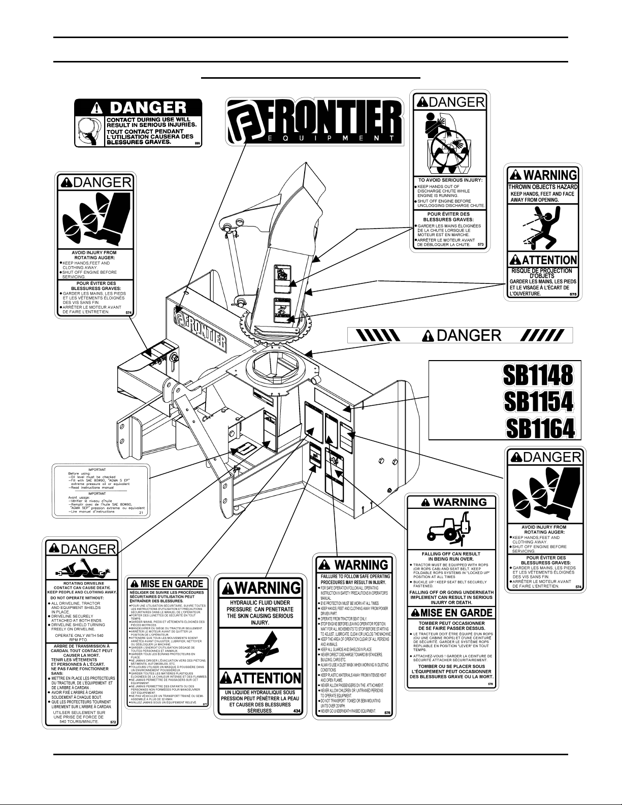
SAFETY DECALS
Replace immediately if damaged.
5RD2500616
5RD2500605
5RD2500617
5RD2500618
5RD2500619
5RD2500606
OM 0369SB1148-A 10
5RD2500611
5RD2500400
Page 13
ASSEMBLY
T
RACTOR PREPARATION
See Dealer for Tractor Preparation information.
S
NOWBLOWER ASSEMBLY
The snowblower is assembled at the factory however snowblower kits must be assembled. Use the
present manual and lay out all parts for assembly. Separate bolts and nuts into various sizes. After
assembly, torque all the bolts according to the Torque Specification Table on page 50.
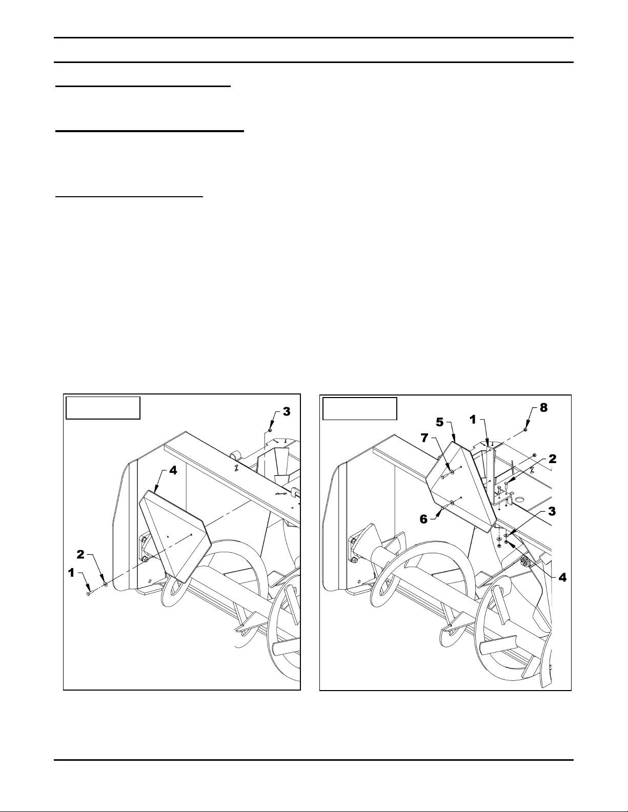
Installation of SMV Sign
(Figures 1-2)
1. Figure 1: Remove the 1/4" NC x 1" bolt, the
flat washer and the 1/4" nylon insert nut
(items 1-2-3) that fixes the sign (item 4) to
the frame. Save the hardware.
2. Figure 2: Install the sign support (item 1) on
the snowblower with two 1/4" NC x 1" bolts,
two 1/4" flat washers and two 1/4" NC nylon
insert nuts (items 2-3-4).
Figure 1
3. Figure 2: Using the hardware previously
removed, attach the SMV sign (item 5) with
two 1/4" NC x 1" bolts, two flat washers and
two 1/4" nylon insert nut (items 6-7-8).
4. Remove the black protective film from the
SMV sign.
Figure 2
OM 0369SB1148-A 11
Page 14

ASSEMBLY
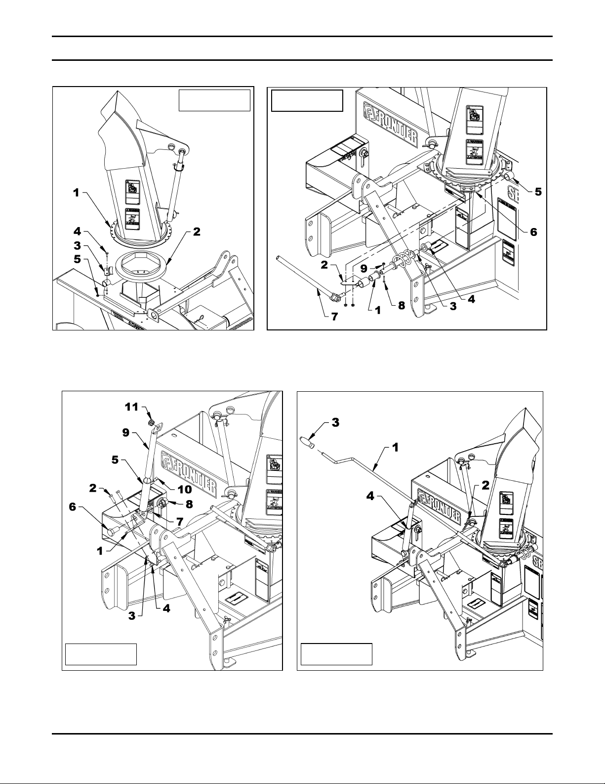
Installation of Chute and Manual Rotation Kit 5RDF0016
(Figures 3-4-5-6)
NOTE: The rotation handle can be installed
on the right or left side of the three point
hitch.
1. Figure 3: Install the rotation bushing
(item 2) over the chute base.
2. Figure 4: Insert the 1 11/16" plastic
bushing (item 1) in the worm support
bracket (item 2) and insert the longest end
of the rotation worm (item 3).
3. Figure 4: Insert the 1 5/16" plastic bushing
(item 4) in the welded tube of the
snowblower (item 5).
4. Figure 4: Place the support (item 2) under
the snowblower's right upper plate (item 6).
5. Figure 3: Place the chute (item 1) over the
rotation bushing (item 2) and install the four
retaining plates (item 3) with eight 1/4" x
3/4" bolts and eight serrated flange nuts
(items 4-5). Tighten securely.
6. Figure 4: Insert the rotation tube (item 7) in
the worm assembly aligning the holes,
insert an Allen socket head capscrew 10-24
x 1" (item 8) making sure the screw head
sinks into the rotation worm and secure
with a nylon insert nut (item 9).
7. Figure 5: Install the rotation bracket
(item 1) on the left or right arm of the three
point hitch with two 3/8" NC x 1 1/4" bolts,
3/8" lockwashers and 3/8" nuts (items 2-3-
4). Tighten firmly.
9. Figure 5: Insert the handle support (item 9)
in the bracket (item 5) adjusting the height
of the support according to your needs and
secure in place with a 3/8" x 1/2" square
head setscrew (item 10).
10. Figure 5: Insert the grommet (item 11) in
the handle support (item 9).
11. Figure 6: Insert the handle (item 1) in the
handle support (item 4) and in the rotation
tube. Select desired length, align nearest
holes and secure with the 4 mm x 80mm
hairpin (item 2). Install the plastic handle
(item 3).
12. Figure 5: Once the snowblower is attached
to the tractor, adjust handle position and
height to ensure comfort and safe
operation. Tighten setscrew (item 10) on
the handle support as well as the 3/4" x
1 1/2" bolt, 3/4" lockwasher and 3/4" nut
(items 6-7-8).
13. Figure 6: To insure the manual rotation
functions properly, position the handle
support (item 4) the closest possible to the
top link mounting point of the three point
hitch while making sure it does not come
into contact with the operator's seat when
the snowblower is fully raised.
14. Tighten all bolts according to the Torque
Specification Table on page 50.
8. Figure 5: Attach the handle support
bracket (item 5) to the rotation bracket
(item 1) with a 3/4"NC x 1 1/4" bolt,
lockwasher and nut (items 6-7-8) making
sure to attach the brackets in the direction
illustrated.
OM 0369SB1148-A 12
CAUTION
To avoid personal injury, check the full lifting
range of the snowblower, to ensure that the
chute rotation handle is clear of the
operator’s area when the snowblower is in
raised position.
Page 15
ASSEMBLY
Figure 3
Figure 4
Figure 5
OM 0369SB1148-A 13
Figure 6
Page 16
ASSEMBLY
3. Magnifying glass
Installation of Chute and Hydraulic Rotation Kit 5RDF0017
(Figures 7-8-9)
1. Figure 7: Place the rotation bushing
(item 2) over the chute base.
2. Figure 7: Place the chute (item 1) over the
rotation bushing (item 2) and install the four
retaining plates (item 3) with eight 1/4" x
3/4" bolts and eight serrated flange nuts
(items 4-5). Tighten securely.
3. Figure 8: Attach the rotation bracket
(item 1) in the ∅21/32’’ hole in the housing
with a 5/8’’NC x 1 1/2’’ hex. bolt, a 5/8"
lockwasher and a 5/8" nut (items 2-3-4).
Note: For SB1148 only. Place the 5/8" lg
spacer (fig. 8, item 5) on the Ø9/16" x 1" slot in
the housing before attaching the other end of
the bracket.
4. Figure 8: Attach the other end of the
bracket (item 1) in the Ø9/16" x 1" slot in
the housing with a 1/2"NC x 1 1/4" hex.
bolt, a Ø9/16" hole flat washer, a 1/2"
lockwasher and a 1/2" hex. nut (items 6-78-9). Tighten securely.
5. Figure 8: Attach the bell crank (item 10) by
inserting the pivot bushing (item 11) in the
tube and slide the bell crank between the
flat bars of the rotation bracket (item 1).
Secure everything with a 5/8’’NC x 5 1/2"
hex. bolt, a 5/8" lockwasher and a 5/8"
stover nut (items 12-13-14) in the order
shown. Tighten firmly.
6. Figure 8: Grease both holes of the push
arm generously (item 15) and slide the
shortest section between the bell crank
arms (item 10). Insert a 3/8’’ x 1 1/4"’ bolt
from the top and secure with a 3/8’’NC
stover nut (items 16-17). Tighten leaving
some movement to the mechanism.
7. Figure 8: Slide the longest of the push arm
(item 15) between the flat bars welded on
the base of the chute. Secure everything
with a 3/8’’ x 1 1/4" hex. bolt and a 3/8"NC
stover nut (items 18-19). Tighten leaving
some movement to the mechanism.
8. Figure 8: Attach the fixed section of the
cylinder (item 20) to the rotation bracket
(item 1, hole "B") and the sliding section to
the bell crank (item 10, hole "A") placing a
Ø 1 1/16" flat washer (item 21) between the
cylinder yoke and the top of the bell crank
and secure with the cylinder pins and the
circlips. Point the hydraulic ports upward as
illustrated.
NOTE: The 1 1/16" hole flat washer (item 21)
prevents the cylinder yoke from rubbing on the
bell crank.
9. Figure 9: Connect the 3/8" ends of both
hoses (item 2) to the cylinder (item 1) and
install a quick coupler with rubber dust cap
(items 6-7) at the end of each hose.
10. Figure 9: Secure the hoses on the three
point hitch with the hose clamp, 3/8" NC x 1
1/2" lg bolt and 3/8" NC nylon insert nut
(items 4-3-5) and attach hoses together
with the nylon tie wraps (item 8) where
needed.
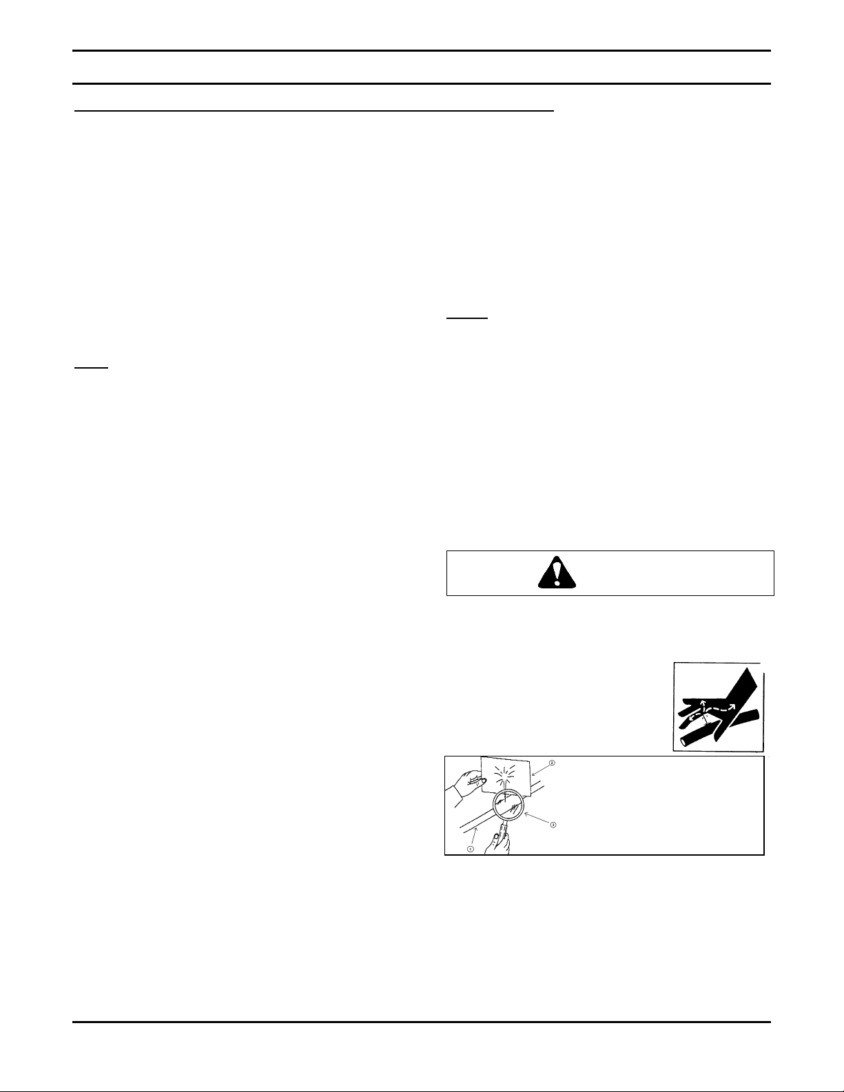
CAUTION
To avoid serious personal injury.
hydraulic/ diesel fluid under pressure can
penetrate the skin causing serious injury.
• Do not use your hands to
check for leaks. Use a
piece of cardboard or
paper to search for leaks.
• Stop engine and relieve pressure before
connecting or disconnecting lines.
• Tighten all connections before starting
engine or pressurizing lines.
If any fluid is injected into the skin, obtain
medical attention immediately or gangrene
may result.
1. Hydraulic hose
2. Cardboard
Escaping
OM 0369SB1148-A 14
Page 17

Figure 7
ASSEMBLY
Figure 8
Figure 9
OM 0369SB1148-A 15
Page 18

ASSEMBLY
Installation of Electric Deflector Kit 5RDF0020 – For SB1154 & SB1164 Only
(Figures 10-11-12 & Electrical Diagram)
1. Figure 10: Install the longest clevis
(item 1) on the actuator base (item 2), the
shortest one (item 3) on the other end and
attach using two 1/2" NC x 2 1/2" bolts and
1/2" NC nylon insert locknuts (items 4-5).
2. Figure 10: Install a 3/16" x 1 3/4" spring
pin (item 6) on each 1" pin (item 7).
3. Figure 10: Attach the actuator on the
chute in the position shown on figure using
two 1" pins (item 7) and secure with 4mm x
80mm hairpins (item 8).
NOTE: The base end of the electric actuator
attaches in the hole closest to the chute.
4. Figure 10 & diagram: Connect the wires
to the switch (item 10) as follows:
• 72" black ground wire (item 9) to terminal
"C" (see diagram).
• 72" red fuse wire (item 11) to terminal "B
(see diagram).
• 360" red and black actuator wires
(item 12) to terminal "A" and "D" (see
diagram).
5. Figure 11: Insert the switch (item 4) in the
switchbox (item 2), secure with the two nuts
(items 1-3) supplied with the switch and
screw the rubber cap (item 5) on the switch
in the order shown.
6. Figure 12: Place the switchbox (item 1) on
the lever in a position that will be
comfortable when the hand is on the knob
and attach with the box clamp (item 5), two
1/4"NC x 3/4" hex. bolts and two 1/4"
lockwashers (items 3-4) making sure the
clamp is in the right direction so the lower
openings on the switchbox are not blocked.
NOTE: Tighten the bolts just enough to securely
fix the clamp and the switchbox on the lever. DO
NOT TIGHTEN TOO MUCH so the clamp
doesn't deform.
Figure 10
OM 0369SB1148-A 16
Page 19

ASSEMBLY
7. Figure 10: Connect the ground wire's
round terminal (item 9) to any grounding
screw on the tractor.
8. Figure 10: Connect the fuse wire (item 11)
to the tractor ignition switch wire using the
tap connector (item 13).
9. Figure 10: Connect the actuator wires'
female connector (item 15) to the electric
actuator (item 2).
10. Figure 10: Place the loom (item 16) around
all the wires to protect them. Secure the
loom using tie wraps.
Figure 11
Figure 12
ELECTRICAL DIAGRAM
OM 0369SB1148-A 17
Page 20

ASSEMBLY
Installation of Hydraulic Deflector Kit 5RDF0019
(Figures 13-14)
1. Figure 13: Remove a circlip (items 1-4)
from each cylinder pin (items 2-3) and
remove the pins. Placing the hydraulic ports
in the position shown on figure 14, attach
the fixed end of the cylinder (item 6) to the
chute base (item 5) and the rod end to the
upper chute bracket with the pins and
circlips (items 1-2-3-4).
2. Figure 14 Connect the 3/8" ends of both
hoses (item 2) to the cylinder (item 1) and
install a quick coupler with rubber dust cap
(items 6-7) at the end of each hose.
3. Figure 14: Secure the hoses on the three
point hitch with the hose clamp, 3/8" NC x
1 1/2" lg bolt and 3/8" NC nylon insert nut
(items 4-3-5) and attach hoses together
with the nylon tie wraps (item 8) where
needed.
Note: Make sure to leave enough slack to the
hoses to allow complete rotation movements.
Figure 13
Figure 14
OM 0369SB1148-A 18
Page 21

ASSEMBLY
Installation of Snowblower with Three Point Hitch
(Figure 15)
1. Install the two cat.1 pins (item 1) on the right
and left snowblower hitches in the lower holes
as shown on figure.
2. Attach tractor lower links (item 2) to the hitch
pins (item 1) and secure with the linchpins
(item 3).
3. Attach the tractor upper link (item 4) between
the upper attaching plates (item 6) using the
tractor pin and linchpin (item 5 – not included).
4. Adjust the snowblower using the tractor upper
link so that the snowblower operates parallel to
the ground.
Before connecting snowblower driveline to
tractor drive shaft, make sure driveline is not
too long in raised, lowered and middle
position. If the driveline is too long it must be
shortened, to avoid damaged to tractor. See
pages 21 to 23 for instructions.
6. Connect driveline to tractor drive P.T.O.
making sure that the driveline is properly
engaged.
CAUTION
5. Set the tractor anti-sway turnbuckles so the
snowblower does not sway. Be sure there is
no contact with the tires.
Figure 15
7. Install the eyebolt (item 7) in the upper hole of
the left or right side of the three point hitch by
screwing the eyebolt nut to the top and locking
eyebolt in place with a 3/8" serrated flange nut
(item 8).
OM 0369SB1148-A 19
Page 22

ASSEMBLY
Installation of Snowblower with Quick Hitch
(Figure 16)
1. Install the two cat.1 pins (item 2) on the
right and left snowblower hitches in the
upper holes leaving 3 1/4" between the jam
nut and the end of the pin as shown on
figure.
2. Insert the two 2 1/8" lg bushings (item 3) on
each pin and secure in place and lock in
place with the two 7/16" linchpins (item 4).
3. Insert the 1 7/8" lg bushing (item 5)
between the upper attaching plates and
lock in place with the tractor hitch pin and a
7/16" linchpin (items 6-7 not included).
CAUTION
Before connecting snowblower driveline to
tractor drive shaft, make sure driveline is not
too long in raised, lowered and middle
position. If the driveline is too long it must be
shortened, to avoid damaged to tractor. See
pages 21 to 23 for instructions.
4. Connect driveline to tractor drive P.T.O.
making sure that the driveline is properly
engaged.
5. Install the eyebolt (item 8) in the upper hole
of the left or right side of the three point
hitch by screwing the eyebolt nut to the top
and locking eyebolt in place with a 3/8"
serrated flange nut (item 9).
Figure 16
OM 0369SB1148-A 20
Page 23

ASSEMBLY
IMPORTANT
A proper initial installation will give you years of
satisfactory service on your equipment. Please
read carefully following instructions that have
been specially included to help you and ensure
you are satisfied with your purchase.
Unfortunately, snowblowers will be faced
with forgotten or hidden objects under the
snow, such as : chain, tires, stones, pieces
of wood, etc. In spite of all our efforts,
machines are not built to resist all those
conditions.
How to Determine Driveline Angles
IMPORTANT:
joint angles, it is recommended to adjust the
three point hitch at the furthest point from the
tractor recommended by the manufacturer
Angles of Driveline Joints Too Large
:
WARNING
To obtain the proper universal
Avoid
Danger: Tractors Too Big
It is dangerous to use a tractor that is too big and
powerful. The tractor will always be able to
overload the blower, even if the machine is
already at maximum capacity. Furthermore,
tractors being very high, the driveline angles will
be excessive which means the universal joints
will be very vulnerable and the life of the driveline
will be dramatically reduced.
The universal joint angle is directly related with
the life of driveline. In order to reduce the angle, it
is necessary to increase the distance between
the snowblower and the tractor.
Reasonable Angles of Driveline Joints
Acceptable
OM 0369SB1148-A 21
Page 24

ASSEMBLY
Unequal Angles at Driveline Joints
Avoid
Angles at Each End of Driveline
A popular habit is to change the snowblower
angle in order to obtain a better scraping effect.
This practice can become harmful to the
driveline since the angle at each end is
unequal. This results in a fan speed variation as
well as a drastic increase of load on cross and
bearings. To be avoided: It is recommended to
always keep tractor driveline and snowblower
input shaft parallel.
Equal Angles at Driveline Joints
Recommended
Figure 17
Determining Driveline Length
IMPORTANT: Before using the equipment,
make sure the driveline is not too long. At
working position, the two half drivelines must
intersect each other sufficiently to insure
maximum efficiency but there must not be any
interference.
1. To determine the "L" length for your tractor
model first find the "X" factor by measuring
the horizontal distance between the end of
the tractor's drive shaft and the end of the
snowblower's driven shaft when the
snowblower is in transport position as shown
on Figure 17.
2. Choose in the table below the "Y" factor
according to the tractor category and deduct
that number from "X" to determine "L" which
is the center-to-center length between the
universal joints.
L = X – Y
3 PTS HITCH
CATEGORY
Y
Cat. 1 4 1/2"
Cat. 2 5 1/2"
OM 0369SB1148-A 22
Page 25

ASSEMBLY
Figure 18
A
NOTE: Before cutting, make sure the two shafts
intersect by at least 7 3/4" when in working
position that is when the snowblower rests on the
ground.
3. Hold the two half-shaft side by side and locate
the "L" length between the two center-tocenter half-shaft universal joints. Mark off the
zone to be cut on both halves opposite each
half-shaft guard as shown on Figure 18
4. Cut off inner and outer guard tubes as well as
the inner and outer telescopic sections.
5. Cut the guard a second time leaving the same
distance between the end of the guard and
the end of the shaft as existed before. To
obtain the proper distance "A" shown on
Figure 19, cut the guard according to the
following table:
DISTANCE A
Male PTO Female PTO
1 3/4" 1 1/4"
6. File down tubes and remove chips.
7. Apply grease to inside of outer telescopic
section.
IMPORTANT: Work with fully guarded shafts
only!
Figure 19
OM 0369SB1148-A 23
Page 26

ASSEMBLY
SB1164
SB1148
Driveline Installation
(Figures 20 -21)
SB1148
(Figure 20)
1. Separate the snowblower from the three
point hitch.
2. Remove paint from snowblower gearbox
shaft (item 2) and grease driveline sliding
surfaces and yoke.
3. Insert the 1/4" x 1/4" x 1 1/4" key (item 1) on
the gearbox shaft. Connect the Ø1" driveline
yoke to the gearbox shaft (item 2). Secure
with a 1/4" NC x 2 1/2" bolt, a 1/4" NC nylon
insert locknut and a 1/4" NC x 3/8" setscrew
(items 3-4-5). Tighten the bolt according to
the Torque Specification Table on page 50.
4. Attach safety chain (item 6) over the upper
link (item 7) to prevent the guard from
spinning.
Figure 20
SB1154 – SB1164
(Figure 21)
1. Separate the snowblower from the three
point hitch.
2. Remove paint from snowblower gearbox
shaft (item 1) and grease driveline sliding
surfaces and yoke (item 2).
3. Remove bolts from the driveline yoke and
slide yoke over drive shaft using the sliding
action of the driveline. Make sure the
driveline is well secured to the shaft by
reinstalling the bolts and nuts (item 3-4) in
the order shown. Tighten the bolts according
to the Torque Specification Table on
page 50.
4. Attach safety chain (item 5) over the upper
link (item 6) to prevent the guard from
spinning.
Figure 21
SB1154
OM 0369SB1148-A 24
Page 27

ASSEMBLY
Removing Snowblower from Tractor
(Figures 22-23-24)
Three Point Hitch
1. Set parking brake and turn engine off.
2. Figure 22: Remove the wire round lock pin
(item 2), lower the parking stand (item 1)
completely to the ground to release all the
pressure on the three point and reinsert the
wire round lock pin in the lower hole (item 3).
3. Figure 23: Detach upper link (item 4) by
removing linchpin and pin (items 6-5).
4. Figure 23: Disconnect driveline from tractor
and attach the driveline safety chain (item 7) to
the three point hitch eyebolt (item 8).
5. Figure 23: Carefully detach lower links
(items 2) from hitch pins (item 1) by removing
linchpins (items 3), loosen anti-sway
turnbuckles and slowly back tractor away from
the snowblower.
IMPORTANT: To avoid damages to the
snowblower, retorque all bolts after the first 10
hours of operation.
Figure 22
Figure 23
OM 0369SB1148-A 25
Page 28

ASSEMBLY
Quick Hitch
1. Figure 22: Remove the wire round lock pin
(item 2), lower the parking stand (item 1)
and reinsert the wire round lock pin in the
lower hole (item 3).
2. Figure 24: Disconnect driveline (item 1)
from tractor and attach the driveline safety
chain (item 2) to the three point hitch eyebolt
(item 3).
3. Figure 24: Slowly back the tractor away to
release quick hitch (item 4) from the
snowblower.
Figure 24
OM 0369SB1148-A 26
Page 29

G
1
ENERAL PREPARATION
OPERATION
A
DJUSTMENTS
1. Read the operator’s manual carefully before
using the tractor and snowblower. Be
thoroughly familiar with the controls and
proper use of the equipment. Know how to
stop the unit and disengage the controls
quickly.
2. Make sure the snowblower is clear of snow
before engaging the driveline.
3. Make sure the auger and fan operate freely.
4. Check the oil level in the worm Gearbox and if
necessary, add 80W90 SAE gear oil, AGMA
5EP oil or equivalent.
5. Check the two shear bolts, one on the driving
shaft, and the one on the PTO, for proper
tightness.
6. Adjust so that the snowblower skid shoes run
level.
7. Wear adequate winter outer garments while
operating equipment.
O
PERATING CONTROLS
Work and Travel Speed
Working ground speed will depend on the depth
and density of the snow to be cleared. Normally,
ground speed will range from 4 to 7 MPH for light,
dry snowfalls 3 to 6 inches, and 1 to 3 MPH for
heavy, wet or drifted snow. To transport,
disengage the drive shaft and raise the
snowblower to full transport height.
Raising and Lowering the Snowblower
Move the three point lever on right hand side of
seat down or forward to lower, and up or rearward
to raise.
Chain Tension Adjustment
(Figure 25)
The premature wear of the chain may be caused by
tension being too tight. It is therefore important not to
tighten chain to its maximum.
• To adjust the tension on the drive chain, loosen the
bolt (item 1) securing the idler sprocket to the
snowblower housing.
• To tighten the chain, lower the bolt. Leave
approximately 1/8" deflection in one span of the
chain. Retighten securely the bolt holding the idler
sprocket.
Skid Shoe Adjustment
(Figure 25)
Adjust the skid shoes so that the snowblower runs
level and according to the surface conditions so that
stones are not thrown with the snow.
Adjust both skid shoes to the same height to keep the
cutting edge level and adjust upwards for smooth
surfaces.
Loosen skid shoe bolts (item 2) and adjust according
to instructions below, and securely tighten bolts:
Clearance between cutting edge and surface:
• Paved surface: Insert bolts in lower hole.
• Uneven or gravel surface: Insert bolts according to
distance needed: 1/2" - middle hole
1" - upper hole
2
WARNING
To avoid personal injury, be sure the tractor
engine is off, the drive shaft disengaged, and
all movement has stopped before making any
adjustments.
OM 0369SB1148-A 27
Figure 25
Manual Deflector Adjustment
Set the angle of deflection according to the distance
the snow must be thrown. To set the deflector angle,
remove the adjusting pipe hairpin and adjust the
adjusting rod to the desired deflector angle. Secure
with the adjusting pipe hairpin.
Page 30

OPERATION
S
NOW REMOVAL METHODS
When removing snow, do not use the snowblower as a dozer blade to push snow. Let the snowblower
work its way through deep drifts. If the speed of your tractor is too fast, the snowblower may become
overloaded and clog. For best results, raise the snowblower and remove a top layer of snow. A second
pass with the snowblower will remove the remaining snow.
IMPORTANT: Use full RPM power when removing wet, sticky snow. Low RPM power will tend to clog the
chute.
Do not use hands or feet to unclog chute. Do not attempt to clear clogged chute of snow while tractor
engine is running. If the chute clogs, disengage the drive shaft, shut off the tractor engine, remove the
ignition key, wait for all movement to stop, and then clear the snow from the chute.
A definite pattern of operation is required to thoroughly clean the snow area. These patterns will avoid
throwing snow in unwanted places as well as eliminating a second removal of snow
WARNING
Where it is possible to throw the snow to the left
and right (above), as on a long driveway, it is
advantageous to start in the middle. Plow from
one end to the other, throwing snow to both sides
without changing the direction of the discharge
guide
OM 0369SB1148-A 28
If the snow can only be thrown to one side of the
driveway or sidewalk (above), start on the opposite
side. At the end of the first pass, rotate the
discharge guide 180 degrees for the return pass.
At the end of each succeeding pass, rotate the
discharge guide 180 degrees to maintain direction
of throw in the same area.
Page 31

MAINTENANCE
M
AINTENANCE
Shearbolts
Check the shearbolts indicated on the figure
below at frequent intervals for proper tightness to
be sure the blower is in safe working condition. If
the shearbolts need replacement, use the
following parts only:
Drive shaft:
WARNING
Provide adequate blocking before working under
the snowblower when in the raised position.
Driveline
SB1148:
Shearbolt hex. 1/4" NC x 1 3/4" gr.5, including
1/4"NC insert locknut. Part # 5RD663837.
SB1154-SB1164
Shearbolt hex. 5/16" NC x 1 3/4" gr.5, incl. nut
PTD Part # 5RD665547.
Driveline:
SB1148:
Bolt M6 x 1.00 x 40mm long gr.8.8 PTD and nut.
Part #5RD4700105
SB1154-SB1164
Bolt M10 x 1.25 x 45mm long gr.8.8 and nut.
Part # 5RD4700060.
SB1148
IMPORTANT: When the snowblower is not
used for more than two weeks, perform
driveline maintenance and always store it in a
dry place, away from bad weather conditions.
SB1154
SB1164
OM 0369SB1148-A 29
Page 32

MAINTENANCE
L
UBRICATION
Use oil or a grease gun and lubricate as follows:
DESCRIPTION
Driveline
Chain
Drive Shaft 24 hours of operation Grease fitting on shear plate
Gearbox
Bearing 24 hours of operation Grease each auger bearing
and after each operation
INTERVAL LUBRICATION REQUIRED
8 hours
16 hours Oil the connections
4 hours
Every month
Once a year Replace oil
Grease each universal joint. Separate the sliding
parts and cover each one of them with grease
Lubricate with chain lube
Check oil level. If needed, add AGMA 5EP extreme
pressure oil, SAE 80W90 gear oil or equivalent.
OM 0369SB1148-A 30
Page 33

MAINTENANCE
D
RIVELINE TROUBLESHOOTING
Q
UICK-DISCONNECT YOKE
AVOIDABLE DAMAGES POSSIBLE CAUSES CORRECTIVE ACTIONS
Quick-disconnect pin tight or
completely seized.
Quick-disconnect pin
damaged (broken or bent)
Quick-disconnect pin
damaged in the locking
portion.
Quick-disconnect pin dirty
(insufficient maintenance).
Quick-disconnect pin
defective (forced
engagement, incorrect
handling)
Excessive shaft length.
Axial loads too high.
Note: Quick-disconnect pins must be cleaned and greased every 16 hours.
Y
OKE
AVOIDABLE DAMAGES POSSIBLE CAUSES CORRECTIVE ACTIONS
Yoke ears deformation
Excessive shaft length.
Axial loads too high.
Excessive working angle
and torque.
Clean, oil and follow service
instructions.
Replace quick-disconnect pin.
Shorten shaft length (cut both
telescopic tubes as well as
shield and remove burrs).
Replace quick-disconnect pin.
Clean and grease telescopic
tubes, and replace both tubes,
if necessary.
Replace quick-disconnect pin.
Shorten shaft length (cut both
telescopic tubes as well as
shields and remove burrs).
Replace defective yokes.
Clean and grease telescopic
tubes, and replace both tubes,
if necessary.
Replace defective yokes.
Verify compatibility between
shaft and working conditions
(torque vs. angle).
Disengage tractor driveline
during cornering or when lifting
or lowering the implement.
Change to a larger driveline
size.
Replace defective yokes.
Yoke ears distorted.
Yoke ears worn or pounded.
OM 0369SB1148-A 31
Overload caused by high
starting and peak torques.
Excessive working angle. Avoid excessive working
Engage driveline more
carefully.
Use appropriate safety
devices.
Replace defective yokes.
angle.
Disengage tractor driveline
during cornering.
Replace defective yokes.
Page 34

MAINTENANCE
C
ROSS KIT
AVOIDABLE DAMAGES POSSIBLE CAUSES CORRECTIVE ACTIONS
Cross arms broken.
Bearing caps turning in their
cross journal.
Overheated bearing caps.
Extreme torque peak or
shock load.
Axial loads too high.
Excessive continuous
torque and/or excessive
working angle.
Inadequate greasing.
Use appropriate safety device.
Change to a larger driveline
size.
Shorten driveline shaft.
Replace defective cross
bearings.
Verify compatibility between
shaft and working conditions.
Carefully follow greasing
instructions.
Replace defective cross
bearings.
Accelerated wear of cross kit. Excessive continuous
torque and/or excessive
working angle.
Inadequate greasing.
Verify compatibility between
shaft and working conditions.
Carefully follow greasing
instructions.
Replace defective cross
bearings.
Note: Cross bearings must be greased every 8 working hours.
AVOIDABLE DAMAGES POSSIBLE CAUSES CORRECTIVE ACTIONS
T
ELESCOPIC TUBES
Telescopic tubes failure or
twisting.
Extreme torque peak or
shock load.
Short tube engagement.
Use appropriate safety device.
Change to a larger driveline
size.
Replace the driveline drive
shaft with one having
adequate length.
Replace defective tubes.
Note: Telescopic tubes must be cleaned and greased every 8 working hours.
Accelerated wear of
telescopic tubes.
Extreme load when sliding.
Short tube engagement.
Inadequate greasing.
Dirt
Change to a driveline with
rilsan coated inner tube.
Replace the driveline with one
having adequate length.
Carefully follow greasing
instructions.
Replace defective tubes.
OM 0369SB1148-A 32
Page 35

MAINTENANCE
SHIELD
AVOIDABLE DAMAGES POSSIBLE CAUSES CORRECTIVE ACTIONS
Excessive wear of shield
bearings.
Chain moving or failure.
Shield cone damaged.
Shield tubes damaged
(deformed and split at one
side).
Insufficient lubrication.
Incorrect chain mounting.
Shield interfering with
implement.
Shield interfering with
implement.
Incorrect chain mounting.
Shield cone in contact with
components on the tractor
and/or implement.
Excessive angularity.
Shields in contact with
components on the tractor
and/or implement.
Shield tubes overlap too
short or no overlap at all
with extended driveline.
Follow lubrication instructions.
Mount chain to allow
maximum angularity.
Avoid contact of the shields
with fixed parts of the machine
or tractor.
Replace shield bearings.
Avoid contact of the shields
with fixed parts of the machine
or tractor.
Mount chain to allow
maximum angularity.
Replace defective parts.
Eliminate interference
between Shield cones and any
part on the tractor and/or
implement.
Avoid excessive angle during
cornering or when lifting or
lowering the implement.
Replace damaged Shield
cones.
Eliminate interference
between Shield cones and
any part on the tractor and/or
implement.
Replace damaged tubes.
Adjust Shield tubes length
with longer tubes.
Note: Shield bearings must be greased every 8 working hours.
OM 0369SB1148-A 33
Page 36

PARTS
I
NTRODUCTION
All parts are illustrated in "exploded views" which show the individual parts in their normal relationship to
each other. Reference numbers are used in the illustrations. These numbers correspond to those in the
"Reference Number" (REF) column, and are followed by the description and quantity required.
Right hand and left hand are determined by those seen by the conductor standing behind the equipment.
The manufacturer reserves the rights to change, modify, or eliminate from time to time, for technical or
other reasons, certain or all data, specifications, or the product or products themselves, without any liability
or obligation.
The parts listed here are available through your local dealer.
M
ANUAL HOLDER – ALL MODELS
REF. D
1 Manual holder 1 5RD4200030
2 Bolt hex. 5/16" NC x 3/4" lg gr. 5, PTD 2 5RD0100018
3 Nut nylon insert 5/16" NC, PTD 2 5RD1000005
ESCRIPTION
QTY P
ART
#
OM 0369SB1148-A 34
Page 37

35
S
NOWBLOWER
PARTS
– SB1148
OM 0369SB1148-A
Page 38

36
S
REF. D
QTY
P
#
NOWBLOWER
PARTS
– SB1148
ESCRIPTION
1 Housing 1 --2 Chute assembly (including adjustment tube and rod) 1 5RD668054
3 Rotation bushing 1 5RD659151
4 Adjustment rod 1 5RD654074
5 Adjustment tube 1 5RD654076
6 Cotter pin Ø1/4" x 2" PTD 2 5RD1500022
7 Round wire lock pin 1/4" x 2" PTD 2 5RD1900006
8 Retaining plate 4 5RD659146
9 Bolt hex. 1/4" NC x 3/4" gr.5 PTD 10 5RD0100003
10 Lockwasher 5/8" PTD 1 5RD1200007
11 Serrated flange nut 1/4" NC PTD 8 5RD0900058
12 Gearbox 1 5RD4500039
13 Auger 1 5RD667636
14 Fan 1 5RD667637
15 Key 1/4" x 1/4" x 2 1/2" lg 1 5RD660924
16 Bolt hex. 5/16" NC x 1 1/4" gr.5 PTD 1 5RD0100020
17 Lockwasher 5/16" PTD 1 5RD1200003
18 Flat washer (hole 7/16" diam.) 1 5RD1400004
19 Sprocket #50A36 1 5RD3300014
20 Driveline, series 20 1 5RD4700100
21 Hitch pin Cat. 1 2 5RD654196
22
Bolt hex. 5/16" NC X 1" gr.5 PTD
23 Bearing 1" hole, 2 holes 2 5RD4300025
24 Bolt hex. 1/2" NC x 1 1/4" gr.5 PTD 4 5RD0100069
25 Lockwasher 1/2" PTD 4 5RD1200006
26 Nut hex. 1/2" NC PTD 4 5RD0900006
27 Chain #50 x 84 links incl. connecting link. 1 5RD3300016
28 Connecting link #50 1 5RD655837
29 Skid shoes, adjustable 2 5RD665664
30 Bolt carriage 3/8" x 3/4" gr.5 PTD 4 5RD0300007
31 Serrated flange nut 3/8" NC black 4 5RD0900065
32 Flat washer 5/8" (hole 11/16" diam.) 2 5RD1400008
33 Spacer 1 13/32" lg 1 5RD668111
34 Sprocket #H50A12 1 5RD655426
35 Spacer 1 1/8" lg 1 5RD668112
36 Shear plate 1 5RD667639
37 Driving shaft 1 5RD667638
38 Oilite bushing 1 5RD4300055
39 Shear bolt hex. 1/4" NC x 1 3/4" gr.5, with nut PTD 1 5RD663837
40 Flange with grease slot 1 5RD4300030
41 Bearing 1" hole with locking collar 1 5RD4300038
42 Flange, 3 holes with grease fitting and groove 1 5RD4300031
43 Bolt carriage 5/16" x 5/8" gr.5 PTD 3 5RD0300001
44
Serrated flange nut 5/16" NC PTD
4
7
ART
5RD0100019
5RD0900036
OM 0369SB1148-A
Page 39

S
NOWBLOWER
PARTS
– SB1148
REF. D
45 Bolt hex. 1/4'' NC x 2 1/2" gr.5 PTD 1 5RD0100248
46 Nylon insert locknut 1/4" NC PTD 6 5RD1000003
47 Allen setscrew 1/4" NC x 3/8" gr.5 black 1 5RD0500005
48 Bolt hex. 3/8" NC x 4 1/2" gr.5 PTD 4 5RD0100040
49 Nut hex. 3/8" NC PTD 4 5RD0900003
50 Lockwasher 3/8" PTD 4 5RD1200004
51 Linchpin 7/16" PTD 2 5RD1900003
52 Grease fitting 1/4" NF 1 5RD654106
53 Bolt hex. 5/8'' NC x 4 1/2" gr.5 PTD 1 5RD0100104
54 Spacer 7/8" lg 1 5RD668110
55 Nut hex. 5/8" - 11 NC PTD 1 5RD0900007
56 Key 1/4" x 1/4" x 1 3/4" lg 1 5RD659579
57 Hairpin 3mm x 65 mm lg 1 5RD1800004
58 Bushing 1.5 OD x 2 1/8" lg PTD 2 5RD668059
59 Bushing 1 1/4" OD x 1 7/8" lg PTD 1 5RD668058
60 Parking Stand 1 5RD668053
61 S.M.V. sign support 1 5RD668109
62 Bolt hex. 1/4" NC x 1 1/4" gr.5 PTD 1 5RD0100005
63 S.M.V. reflective sign 1 5RD4200029
64 Driveline shield 1 5RD668057
65 Driveline shield bracket 1 5RD668052
66 Bolt hex. 1/4" NC x 1" lg gr.5 PTD 4 5RD0100004
67 Flat washer 1/4" (hole 5/16" diam.) PTD 6 5RD1400002
68 Eyebolt 3/8" NC x 4" lg inc. nut 1 5RD0400027
69 Lockwasher 1/4" PTD 2 5RD1200002
70 Nut hex. 1/4" NC PTD 2 5RD0900001
71 Hand guard 1 5RD657308
ESCRIPTION
QTY P
ART
#
OM 0369SB1148-A
37
Page 40

S
NOWBLOWER
PARTS
– SB1154 & SB1164
OM 0369SB1148-A
38
Page 41

S
NOWBLOWER
PARTS
– SB1154 & SB1164
REF. D
1 Housing 1 --- --2 Chute assembly (including adjustment tube and rod) 1 5RD668054 5RD668054
3 Rotation bushing 1 5RD659151 5RD659151
4 Adjustment rod 1 5RD654074 5RD654074
5 Adjustment tube 1 5RD654076 5RD654076
6 Cotter pin Ø1/4" x 2" PTD 2 5RD1500022 5RD1500022
7 Round wire lock pin 1/4" x 2" PTD 2 5RD1900006 5RD1900006
8 Retaining plate 4 5RD659146 5RD659146
9 Bolt hex. 1/4" NC x 3/4" gr.5 PTD 8 5RD0100003 5RD0100003
10 Lockwasher 5/8" PTD 1 5RD1200007 5RD1200007
11 Serrated flange nut 1/4" NC PTD 8 5RD0900058 5RD0900058
12 Gearbox 1 5RD663485 5RD663485
13 Auger 1 5RD666259 5RD666269
14 Fan 1 5RD668965 5RD668965
15 Key 3/8" x 3/8" x 2 3/4" lg 1 5RD654174 5RD654174
16 Bolt hex. 3/8"NC x 1 1/2" gr.5 PTD 1 5RD0100040 5RD0100040
17 Lockwasher 3/8" dia. hole PTD 1 5RD1200004 5RD1200004
18 Flat washer (7/16" dia. hole) PTD 1 5RD1400004 5RD1400004
19 Sprocket #60A32 1 5RD654167 5RD654167
20 Driveline series 40 1 5RD4700159 5RD4700159
21 Hitch pin Cat. 1 2 5RD654196 5RD654196
22
23 Flange bearing 1 1/4" hole, 4 holes 2 5RD4300001 5RD4300001
24 Bolt hex. 1/2"NC x 1 1/2" gr.5 PTD 8 5RD0100070 5RD0100070
25 Lockwasher 1/2" PTD 8 5RD1200006 5RD1200006
26 Nut hex. 1/2" NC PTD 8 5RD0900006 5RD0900006
27 Chain #60 x 72 links, incl. connect. link 1 5RD659143 5RD659143
28 Connecting link #60 1 5RD654839 5RD654839
29 Left adjustable skid shoe 1 5RD666254 5RD666254
30 Bolt carriage 1/2" NC x 1" lg gr. 5 PTD 4 5RD0300022 5RD0300022
31 Serrated flange nut 1/2" NC PTD 4 5RD0900046 5RD0900046
32 Flat washer 5/8" (11/16" dia. hole) PTD 2 5RD1400008 5RD1400008
33 Spacer 1 3/4" lg 1 5RD668093 5RD668093
34 Sprocket 60A12 1 5RD3300022 5RD3300022
35 Spacer .656"int. x .807 lg x 1" ext. 1 5RD667777 5RD667777
36 Shear plate 1 5RD666257 5RD666257
37 Driving shaft 1 5RD666256 5RD666268
38 Oilite bushing 1 5RD4300056 5RD4300056
39 Shearbolt hex. 5/16"NC x 1 3/4" gr.5, incl. nut 1 5RD665547 5RD665547
40 Flange, 3 holes with grease groove 1 5RD4300014 5RD4300014
41 Bearing 1 1/8" with setscrew and grease system 1 5RD4300040 5RD4300040
42 Flange with tip and grease fitting 1 5RD4300015 5RD4300015
43 Bolt carriage 3/8" x 3/4" lg gr.5 PTD 3 5RD0300007 5RD0300007
44 Serrated flange nut 3/8" NC PTD 8 5RD0900035 5RD0900035
45 Fan washer 1 5RD661554 5RD661554
ESCRIPTION
Bolt hex. 3/8"NC x 1 1/2" gr.5 PTD 4 5RD0100040 5RD0100040
Right adjustable skid shoe 1 5RD666255 5RD666255
QTY
SB1154 SB1164
OM 0369SB1148-A
39
Page 42

S
NOWBLOWER
PARTS
– SB1154 & SB1164
REF. D
46 Nylon insert locknut 1/4" NC PTD 5 5RD1000003 5RD1000003
47 Flat washer 1/4" NC (5/16" dia. hole) PTD 4 5RD1400002 5RD1400002
48 Bolt hex. 3/8"NC x 5" gr.5 PTD 4 5RD0100051 5RD0100051
49 Nylon insert locknut 3/8" NC PTD 4 5RD1000006 5RD1000006
50 Bolt hex. 1/4" NC x 1" lg PTD 4 5RD0100004 5RD0100004
51 Linchpin 7/16" PTD 2 5RD1900003 5RD1900003
52 Grease fitting 1/4" NF 1 5RD654106 5RD654106
53 Bolt hex. 5/8'' NC x 4 1/2" gr.5 PTD 1 5RD0100104 5RD0100104
54 Spacer 1 3/32
55 Nut hex. 5/8" -11 NC PTD 1 5RD0900007 5RD0900007
56 Driveline shield bracket 1 5RD668052 5RD668052
57 Hairpin 3mm x 65mm lg. 1 5RD1800004 5RD1800004
58 Bushing 1.5 OD x 2 1/8" lg PTD 2 5RD668059 5RD668059
59 Bushing 1 1/4" OD x 1 7/8" lg PTD 1 5RD668058 5RD668058
60 Parking stand 1 5RD668053 5RD668053
61 S.M.V. sign support 1 5RD668109 5RD668109
62 Bolt hex. 1/4" NC x 1 1/4" gr.5 PTD 1 5RD0100005 5RD0100005
63 S.M.V. reflective sign 1 5RD4200029 5RD4200029
64 Driveline shield 1 5RD668057 5RD668057
65 Lockwasher 1/4" PTD 2 5RD1200002 5RD1200002
66 Nut hex. 1/4" NC, PTD 2 5RD0900001 5RD0900001
67 Hand guard 1 5RD657308 5RD657308
68 Eyebolt 3/8" NC x 4" lg inc. nut 1 5RD0400027 5RD0400027
ESCRIPTION
QTY SB1154 SB1164
"
1
5RD667015 5RD667015
OM 0369SB1148-A
40
Page 43

PARTS
5RD4500039
G
EARBOXES
REF. D
ESCRIPTION
1 Casing 2 5RD4500058 2 5RD659848
2 Bearing 2 5RD4300059 2 5RD659844
3 Shim 2 5RD661731 1 5RD656649
4 Input shaft 1 5RD4500059 1 5RD664663
5 Shim 1 5RD661733 2 5RD659855
6 Oil seal 3 5RD661730 3 5RD659852
7 Snap ring 2 5RD661734 2 5RD656652
8 Gear 1 5RD4500061 2 5RD662236
9 Parallel key 1 5RD660063 2 5RD659850
10 Output shaft 1 5RD4500060 1 5RD659853
11 Bearing 2 5RD4300058 2 5RD659844
12 Plug 1 5RD661739 1 5RD659847
13 O-ring 1 5RD661144 1 5RD661144
14 Allen socket head cap screw M8 x 1.25mm x 45mm – 8.8. 8 5RD0800036 - -
Allen socket head cap screw M8 x 1.25mm x 55mm – 8.8. - - 8 5RD0800032
15 Stover locknut M8 x 1.25mm - 8 8 5RD0900063 8 5RD0900063
16 Shim - - 1 5RD659854
Q
5RD4500039
for SB1148
TY
P
ART
# Q
5RD663485
for SB1154-SB1164
TY
P
ART
#
OM 0369SB1148-A
5RD663485
41
Page 44

PARTS
D
RIVELINE
REF. D
1 Quick disconnect yoke Ø1 3/8", 6 splines 1 5RD4700113
2 Journal Cross 2 5RD4700107
3 Yoke 1 5RD4700111
4 Male Shaft 1 5RD4700112
5 Female Shaft 1 5RD4700109
6 Yoke 1 5RD4700108
7 Yoke Ø1 3/8", 6 splines 1 5RD4700104
8 Push pin set 1 5RD663151
9 Shear bolt M6 x 40 mm 8.8 and nut 1 5RD4700105
10 Ball 7/32" 24 5RD4700106
11 Grease fitting 1 5RD657198
12 Shield and chain 1 5RD4700110
13 Pin for yoke (# 6) 1 5RD4700062
14 Pin for yoke (# 3) 1 5RD4700114
5RD4700100
ESCRIPTION
QTY P
FOR
SB1148
ART
#
OM 0369SB1148-A
42
Page 45

PARTS
D
RIVELINE
REF. D
1 Yoke ass'y 1 5RD660764
2 Journal cross 2 5RD660765
3 Yoke for female tube 1 5RD663189
4 Female tube 1 5RD4700160
5 Male tube 1 5RD4700161
6 Yoke for male tube 1 5RD663193
7 Yoke ass'y 1 5RD4700058
8 Bolt M12 x 1.25 x 70 with nut 2 5RD662199
9 Grease fitting 1 5RD 663129
10 Ball Ø1/4" 23 5RD 663163
11 Shear bolt 8mm x 1.25 x 50 gr.5.8 and nut 1 5RD 4700060
12 Protector and chain 1 5RD4700164
13 Pin for outer tube 1 5RD 4700061
14 Pin for inner tube 1 5RD 4700062
5RD4700159
ESCRIPTION
QTY P
FOR
SB1154 & SB1164
ART
#
OM 0369SB1148-A
43
Page 46

PARTS
1 Handle
1
5RD664902
2 Rotation tube
1
5RD660188
3 Handle support
1
5RD660187
4 Handle support bracket
1
5RD660269
5 Rotation worm
1
5RD659161
6 Worm support bracket for SB1148
-
SB1154 & SB1164
1 5RD659145
7 Bracket
1
5RD660388
8 Plastic handle
1
5RD656797
9 Plastic grommet
1
5RD657390
10 Plastic bushing 1 5/16"
1
5RD657335
11 Plastic bushing 1 11/16"
1
5RD657336
12 Hairpin 4mm x 80mm
1
5RD1800002
13 Bolt hex. 3/8"NC x 1 1/4" PTD
2
5RD0100039
14 Allen socket head capscrew 10
-
24 x 1" PTD
1
5RD0800009
15 Square head setscrew 3/8" x 1/2" black
1
5RD0600006
16 Nut hex. 3/8" NC PTD
2
5RD0900003
17 Nylon insert locknut 10
-
24 PTD
1
5RD1000002
18 Lockwasher 3/8" PTD
2
5RD1200004
19 Bolt hex. 3/4
"NC x 1 1/2" PTD
1
5RD0100115
20 Nut hex. 3/4" NC PTD
1
5RD0900008
21 Lockwasher 3/4" PTD
1
5RD1200008
22 Spring pin 1/4" x 1 1/4" lg PTD
2
5RD1600015
23 Universal block
1
5RD658193
24 Rotation yoke
1
5RD659595
25 Worm support bracket (for SB1174 & S
B1184 only)
1
5RD668477
5RDF0016 - M
REF. D
ESCRIPTION
ANUAL ROTATION FOR
QTY P
SB1148 – SB1154 – SB1164
ART
#
OM 0369SB1148-A
44
Page 47

PARTS
REF. D
QTY
P
#
5RDF0017 - H
ESCRIPTION
1 Rotation bracket 1 5RD668541
2 Bell crank 1 5RD667703
3 Push arm 1 5RD667704
4 Pivot bushing 1 5RD667706
5 Bolt hex. 5/8" NC x 5 1/2", gr. 5 PTD 1 5RD0100106
6 Lockwasher 5/8" PTD 2 5RD1200007
7 Stover nut hex 5/8" NC PTD 1 5RD1100007
8 Bolt hex. 5/8" NC x 1 1/2" gr. 5 PTD 1 5RD0100095
9 Nut hex. 5/8" NC PTD 1 5RD0900007
10 Bolt hex. 1/2" NC x 1 3/4", gr.5 PTD 1 5RD0100071
11 Flat washer 9/16" hole PTD 1 5RD1400006
12 Lockwasher 1/2" PTD 1 5RD1200006
13 Nut hex. 1/2" NC PTD 1 5RD0900006
14 Flat washer 1 1/16" hole PTD 1 5RD1400013
15 Bolt hex. 3/8" NC x 1 1/4" gr. 5 PTD 2 5RD0100039
16 Stover nut hex 3/8" NC PTD 2 5RD1100003
17 Decal "Danger" 1 5RD664548
18 Spacer ring 1 5RD668542
19 Cylinder 2" X 6" inc. pins 1 5RD3900002
Seal kit 1 5RD2600047
20 Hose 3/8" x 82" lg 3/8" NPT RM x 1/2" NPT RM 2 5RD3700142
21 Hose clamp 1 5RD660440
22 Bolt hex. 3/8" NC x 1 1/2 gr.5 PTD 1 5RD0100040
23 Nut nylon insert 3/8 NC PTD 1 5RD1000006
24 Quick coupler 1/2-14 NPT male 2 5RD656480
25 Dust cap for male quick coupler 2 5RD664898
YDRAULIC ROTATION FOR
SB1148–SB1154–SB1164
ART
OM 0369SB1148-A
45
Page 48

PARTS
46
REF. D
QTY
P
#
5RDF0019 - H
ESCRIPTION
1 Cylinder 2" X 6" inc. pins 1 5RD3900002
Seal kit 1 5RD2600047
2 Hose 3/8" x 100" lg 3/8" NPT RM x 1/2" NPT RM 2 5RD3700144
3 Quick coupler 1/2" NPT male 2 5RD656480
4 Dust cap 2 5RD664898
5 Hose clamp 1 5RD660440
6 Bolt 3/8" NC x 1 1/2" lg PTD 1 5RD0100040
7 Nut nylon insert 3/8" NC PTD 1 5RD0900003
8 Tie wraps 8" x 4.8 mm black 3 5RD2100003
YDRAULIC DEFLECTOR FOR
SB1148–SB1154–SB1164
ART
OM 0369SB1148-A
Page 49

PARTS
47
5RDF0020- E
REF. D
1
2
3
4
5
6
7
8
9
10
11
12
13
14
15
16
17
18
19
20
ESCRIPTION
Electric actuator 1 5RD665573
Switch box 1 5RD667557
Switch 1 5RD663383
Rubber cap 1 5RD658666
Box clamp 1 5RD667558
Clevis – rod end 1 5RD666049
Clevis – base 1 5RD666051
Pin 1" 2 5RD666057
Ground wire 72" (black) 1 5RD666054
Tap connector 1 5RD656665
Fuse wire 72" (red) 1 5RD666055
Actuator wire 1 5RD666056
Spring pin 3/16" x 1 3/4" black 2 5RD1600009
Hairpin 4mm x 80mm, PTD 2 5RD1800002
Bolt hex. 1/4" NC x 3/4" PTD 4 5RD0100003
Bolt hex. 1/2"NC x 2 1/2", PTD 2 5RD0100076
Nylon insert locknut 1/2"NC, PTD 2 5RD1000011
Loom 3/8" x 420" 1 5RD666053
Lockwasher 1/4" PTD 2 5RD1200002
Tie wraps 8" lg x 4 mm 5 5RD2100003
LECTRIC DEFLECTOR FOR
QTY P
SB1154 – SB1164 O
NLY
ART
#
OM 0369SB1148-A
Page 50

TORQUE SPECIFICATION TABLE
48
NOTE: These values apply to fasteners as received from supplier, dry, or when lubricated with normal engine oil. They do not apply if special graphited
or moly sidulphide greases or other extreme pressure lubricants are used. This applies to both UNF and UNC threads.
SEE Grade No. 2 5 8
BOLT HEAD IDENTIFICATION
MARKS AS PER GRADE
NOTE: MANUFACTURING
MARKS WILL VARY.
BOLT SIZES Pounds-Foot Newtons-Meter Pounds-Foot Newtons-Meter Pounds-Foot Newtons-Meter
Inches Millimeters MIN. MAX. MIN. MAX. MIN. MAX. MIN. MAX. MIN. MAX. MIN. MAX.
Coarse thread Fine Thread
Size of
screw
Grade No.
Torque Torque Torque
Pitch
mm
4T
M6
7T
1.0
8T
4T
M8
7T
1.25
8T
4T
M10
7T
1.5
8T
4T
M12
7T
1.75
8T
4T
M14
7T
2.0
8T
4T
M16
7T
2.0
8T
4T
M18
7T
2.0
8T
4T
M20
7T
2.5
8T
Use the following torques when special torques are not given
Pounds-Foot Newtons-Meter Pounds-Foot Newtons-Meter
MIN. MAX. MIN. MAX.
3.6
5.8
7.2
7.2
17
20
20
34
38
28
51
57
49
81
96
67
116
129
88
150
175
108
186
213
GENERAL SPECIFICATION TABLE
METRIC BOLT TORQUE SPECIFICATIONS
Pitch mm
5.8
9.4
10
14
22
26
25
40
46
34
59
66
56
93
109
77
130
145
100
168
194
130
205
249
4.9
7.9
9.8
9.8
23
27.1
27.1
46.1
51.5
37.9
69.1
77.2
66.4
109.8
130.1
90.8
157.2
174.8
119.2
203.3
237.1
146.3
252
288.6
7.9
12.7
13.6
19.0
29.8
35.2
33.9
54.2
62.3
46.1
79.9
89.4
75.9
126
147.7
104.3
176.2
196.5
136
227.6
262.9
176.2
277.8
337.4
-
1.0
1.25
1.25
1.5
1.5
1.5
1.5
MIN. MAX. MIN. MAX.
-
-
-
12
19
22
20
35
40
31
56
62
52
90
107
69
120
140
100
177
202
132
206
246
-
-
-
17
27
31
29
47
52
41
68
75
64
106
124
83
138
158
117
199
231
150
242
289
-
-
-
16.3
25.7
29.8
27.1
47.4
54.2
42
75.9
84
70.5
122
145
93.5
162.6
189.7
136
239.8
273.7
178.9
279.1
333.3
-
-
-
23.0
36.6
42
39.3
63.7
70.5
55.6
92.1
101.6
86.7
143.6
168
112.5
187
214.1
158.5
269.6
313
203.3
327.9
391.6
OM 0369SB1148-A
Page 51

Page 52

PART NO.
5RDSB1148A
All Rights Reserved
 Loading...