

Page 1

O P E R A T O R ’ S M A N U A L
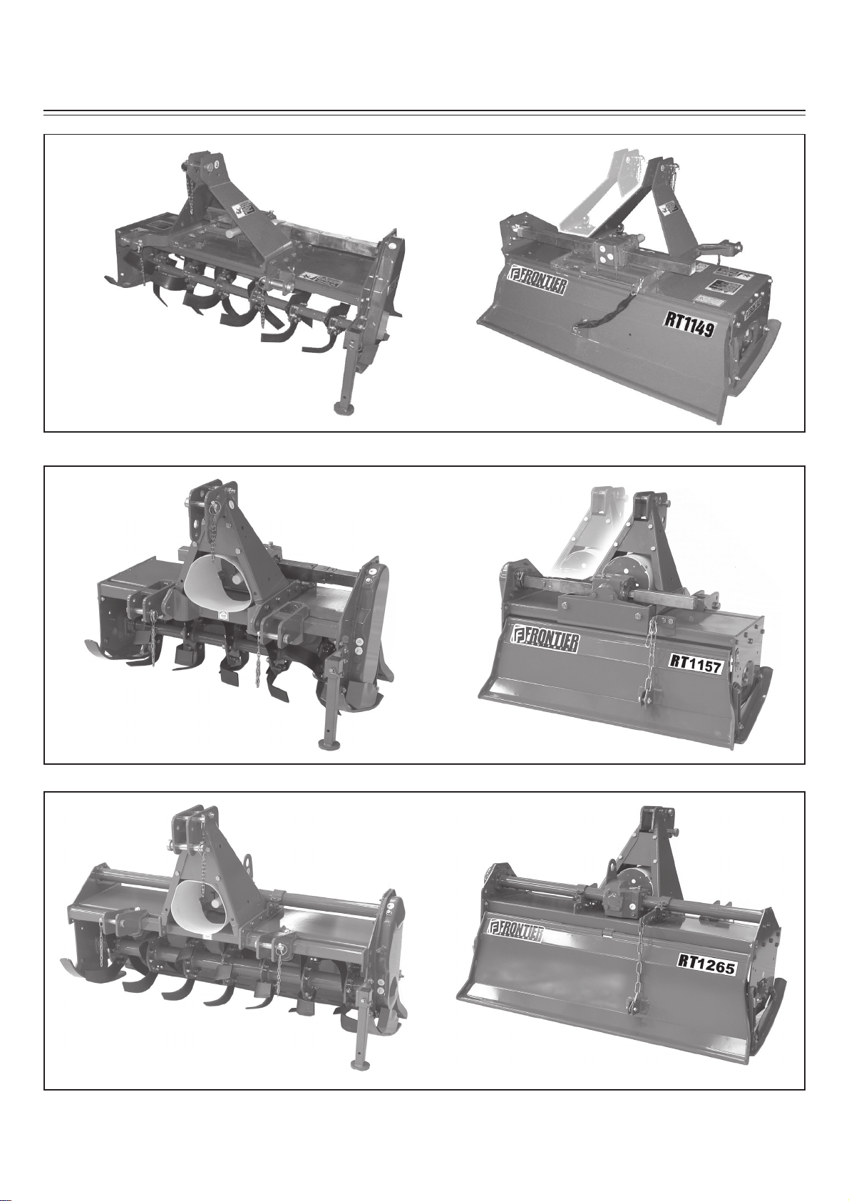
ROTARY TILLERS
RT 1142
RT 1149
RT 1157
RT 1165
RT 1265
Cod. F07010181 / Rev. 05 (2011-09)
Page 2

TABLE OF CONTENTS
Technical specifi cation
Technical specifi cation .................................. 4
Technical specifi cation - Hitch ...................... 6
Safety signs
Safety-Alert simbol ....................................... 7
Identifi cation machine .................................. 7
Machine safety labels ................................... 7
Machine safety labels and positions
Machine safety labels and positions ............. 8
Preparing the vehicle
Preparing the tractor ..................................... 10
Park vehicle safety ........................................ 10
Stay clear of rotating drivelines .................... 10
Installing
Installing tiller on tractor ................................ 10
PTO shaft ..................................................... 12
PTO shaft with shear pin .............................. 13
PTO shaft with clutch ................................... 13
Quick Coupler (optional) ............................... 14
Park vehicle safety ........................................ 14
Stay clear of rotating drivelines .................... 14
Removing
Removing tiller .............................................. 15
Removing tiller with Quick Coupler ............... 15
Operating
Operate safetly ............................................. 16
Wear appropriate clothing ............................ 17
Stay clear of rotating driveline ...................... 17
Raising parking stand ................................... 17
Lowering parking stand ................................ 17
Leveling attachments (side-to-side) .............. 17
Leveling tiller (front-to-r ear) .......................... 18
Adjusting skid shoes .................................... 18
Adjusting levelling board ............................... 18
Adjustable offset ........................................... 19
Tilling tips ..................................................... 20
During tilling ................................................. 20
Replacement parts ....................................... 20
Service Machine Safely
Practice safe maintenance ........................... 21
Wear appropriate clothing ............................ 21
Stay clear of rotating drivelines .................... 21
Service lubrication
Service lubrication ........................................ 22
Every 8 work hours ....................................... 22
Every 50 work hours ..................................... 22
Every 400 work hours ................................... 22
Every 1000 work hours ................................. 22
Greasing and lubricant points ....................... 23
Lubricants ..................................................... 23
Service
Chain stretcher ............................................. 24
Service intervals ........................................... 24
Bolts tightening torques ................................ 24
Replacing tines ............................................. 24
Tines ............................................................. 25
Troubleshooting
Using troubleshooting chart ......................... 26
Storing machine
Storing tiller .................................................. 27
Removing tiller from storage ......................... 27
Assembly / Spare parts
RT 1142-1149 ................................................ 28
RT 1157-1165................................................. 30
RT 1265 ....................................................... 32
Installing driveline on tiller ............................ 34
Spare parts ................................................... 34
Page 3

TO THE DEALER:
Assembly and prope r installation of this product is the responsibility of the Frontier dealer. Read manual
instruction and safe ty rules. Mak e sure all items o n the Deale r’ s P re-D eliv e ry Check List in the Operat or’ s
Manual are completed before releasing equipment to the owner.
The dealer must complete the Warranty Registration, located on the Frontier website. Warranty claims
will be denied if the Warranty Registration has not been completed.
T O THE OWNER:
Read this manual before operating your fronti er equipment. The information presented will prepare you
to do a better and a safe r job. Keep this manual handy for ready reference. Require all operators to read
this manual carefully and become acquainted with all the adjustment and operating procedures before
attempting to operate. Replacement manuals can be obtained from your selling dealer.
The equipment you ha v e p urchased has bee n carefull y e ngine r eed and manufactur ed to pr o vide depe ndable and satisfactory use. Like all mechanical products, it will require cleaning and upkeep. Lubricate
the unit as specifi ed. Observe all safety information in this manual and safety decals on the equipment.
For service, y our authorized Frontier dealer has trained mechanics, genuine Fro ntier service parts, and
the necessary tools and equipment to handle all your needs.
Use only genuine Frontier service parts.Substitute parts will void the warranty and may not meet standards required for safe and satisfactory operation. Record the model number and serial number of your
equipment in the spaces provided:
Model: Date of Purchase
Serial Number:
Provide this information to your dealer to obtain correct repair parts.
Throghout this manual, the term IMPORTANT is used to indicate that failure to observe can cause da-
mage to equipment. The terms CAUTION, WARNING and DANGER are used in conjunction with the
Safety-Alert Symbol, (a triangle with an esclamation mark), to indicate the degree of hazard for items of
personal safety.
(see Safety Decal section for location)
This Safety-Ale rt Simbol indicates a hazard and means ATTENTION! BECOME
ALERT! YOUR SAFETY IS INVOLVED!
DANGER
WARNING
CAUTION
Indicates an imminently hazardous situation that, if not avoid ed , will result in
death or serious injury.
Indicates a potentially hazardous situation that, if not avoi d ed , c ould result in
death or serious injury, and includes hazards that are exposed when guards
are removed.
Indicates a potentially hazardous situation that, if not avoi ded, m ay result in
minor or moderate injury.
IMPORTANT
NOTE
Indicates that a failure to observe can cause damage to equipment.
Indicates helpful information.
Cod. F07010181 / Rev. 05 (2011-09)
Page 4
TECHNICAL SPECIFICATIONS
RT 1142 - 1149
(Adjustable offset)
RT 1157 - 1165
(Adjustable offset)
RT 1265
Technical specifi cations - Page 4
Page 5

TECHNICAL SPECIFICATIONS
RT 1142 - 1149
Model Work/width Tractor HP Tractor HP Weight Side PTO Speeds Input Hitch Max Tines Rotor Rotor
inches min max lbs. Drive shaft gear box speed offset STD blades fl anges
RT 1142 42 10-20 25 293
RT 1149 49 10-20 25 323
Chain Shear Cat. “I”
ASA Pin
80 coupler
Chain Radial Cat. “I”
ASA Slip
80 Clutch coupler
Single 540
Single 540
Quick
Quick
3.9” “C” 4 5
7.9” “C” 4 6
RT 1157 - 1165
Model Work/width Tractor HP Tractor HP Weight Side PTO Speeds Input Hitch Max Tines Rotor Rotor
inches min max lbs. Drive shaft gear box speed offset STD blades fl anges
RT 1157 57 25 40 480
Chain Cat. “I”-”II”
RT 1165 65 30 40 534
Chain Cat. “I”-”II”
ASA Slip
80 Clutch coupler
ASA Slip
80 Clutch coupler
Single 540
Single 540
Quick
15.5” “C” 6 7
Quick
18.1” “C” 6 8
RT 1265
Model Work/width Tractor HP Tractor HP Weight Side PTO Speeds Input Hitch Tines Rotor Rotor
inches min max lbs. Drive shaft gear box speed STD blades fl anges
RT 1265 65 30-50 60 616
ASA Slip
100 Clutch coupler
Chain Cat.“I”-”II”
Single 540
Quick
“C” 6 8
Technical specifi cations - Page 5
Page 6

mm 823 - inch 32.4 cat. II
=
=
mm 681 - inch 26.8 cat. I
TECHNICAL SPECIFICATIONS - HITCH
RT 1142 and 1149: Cat. «I» Standard
RT 1142 and 1149: Cat. «I» Quick Coupler
=
mm 679
inch 26.73
Without bushings: Cat. «I» Standard
With bushings: Cat. «I» Quick Coupler
=
RT 1157 and 1165 : Cat. «I» and «II» Standard
=
mm 681 - inch 26.8 cat. I
mm 823 - inch 32.4 cat. II
=
Without bushings: Cat. «I» Standard
With bushings: Cat. «II» Standard
RT 1265: Cat. «I» and «II» Quick Coupler
Cat. II pin Ø mm 25 (inch 0.984)
Cat. I pin Ø mm 19
(inch 0.748)
Cat. I and II Quick Coupler
pin Ø mm 32 (inch 1.26)
RT 1157 and 1165 : Cat. «I» and «II» Quick Coupler
Cat. I and II Quick Coupler
pin Ø mm 32 (inch 1.26)
=
mm 681 - inch 26.8 cat. I
mm 823 - inch 32.4 cat. II
=
With bushings
RT 1265: Cat. «I» and «II» Standard
Cat. II Std. pin Ø mm 25
(inch 0.984)
Cat. I Std. pin Ø mm 19
(inch 0.748)
With bushings
Without bushings: Cat. I Standard
With bushings: Cat. II Standard
Hitch - Page 6
=
mm 681 - inch 26.8 cat. I
mm 823 - inch 32.4 cat. II
=
Page 7

SAFETY SIGNS
Safety-alert symbol
Read and recognize safety information.
Be alert to the potential for personal injury when you see this safety-alert symbol.
On your machine safety labels , th e wor ds D ANGER, WARNING, and CA UT ION are used with saf ety-ale rt
symbol.
DANGER identifi es the most serious hazards. In this manual, the word CAUTION and this symbol call
attention to safety messages.
Identifi cation machine
Identifi cation plate machine
Machine safety labels
1) WARNING: AVOID INJURY FROM ROTATING KNIVES:
• Keep hands, feet and clothing away.
2) WARNING: AVOID INJURY FROM PTO:
• Keep all shields in place. Keep hands, feet and clothing away.
• Operate only with 540 RPM.
3) CAUTION: AVOID INJURY
• Read Operator’s Manual
• Ballast power unit per operator’s manual
• Know location and function of controls
• Keep all shields in place
• Stay clear of power driven parts
• Never carry riders
• Keep people and pets a safe distance away from machine
BEFORE DISMOUNTING OR SERVICING
• Shut off engine and remove key
• Lock brake for park
• Lower or block up machine
4) DANGER: ROTATING DRIVELINE - CONTACT CAN CAUSE DEATH - KEEP AWAY! - DO NOT
OPERA TE WI THOUT:
• All driveline, tractor and equipment shields in place
• Drivelines securely attached at both ends
• Drivelines shields that turn freely on driveline.
5) DANGER: SHIELD MISSING DO NOT OPERATE
Picture Note: Separate telescoping driveshaft members to locate safety label. Label attached to outer profi le
tube.
Safety Signs - Page 7
Page 8

RT 1142 - 1149
3
1
RT 1157 - 1165
MACHINE SAFETY LABELS AND POSITIONS
2
1
1
RT 1265
1
3
2
1
3
2
1
2
3
4
5
4
Safety Signs - Page 8
5
Page 9

MACHINE SAFETY LABELS AND POSITIONS
11
11
RT 1142 - 1149
6
7
10
6
8
9
MAX
Kg...
6
7
GREASE
RT 1157 - 1165
6
10
6
8
10
7
OIL
LEVEL
8
8
9
12
7
OIL
9
RT 1265
6
10
8
9
11
12
6) Coupling point for lifting (indicating the maximun capacity)
7) Greasing point
8) Oil level plug
9) Oil drain plug
10) Oil fi ll plug
11) Number of revolutions of power takeoff
12) Warning, slow machine (only for model: 1157 and 1265)
10
6
8
OIL
10
7
540
MAX
11
12
Safety Signs - Page 9
Page 10
PREPARING THE VEHICLE
Preparing the tractor
CAUTION: Avoid injury. Proper ballastings is required for safe operation of your tiller
IMPORTANT: Refer to the tractor operator manual for proper ballasting information and tire infl a-
tion
• A 540 rpm PTO
• Refer to the tractor operator is manual for correct ballast ing and tire pressure, depending on installed
equipment.
Park vehicle safety
• Stop vehicle on a lever surface, not on a slope.
• Disengage PTO.
• Engage the park brake.
• STOP the engine.
• Remove the key.
• Before yo u le ave the o perator ’s seat, wai t for en gine
and all moving parts to STOP.
Stay clear of rotating drivelines
Entanglement in rotating driveline can cause serious
injury or death:
• Wear close fi tting clothing.
• ST OP the eng ine and be sure PT O driv eline is stopped
before getting near it.
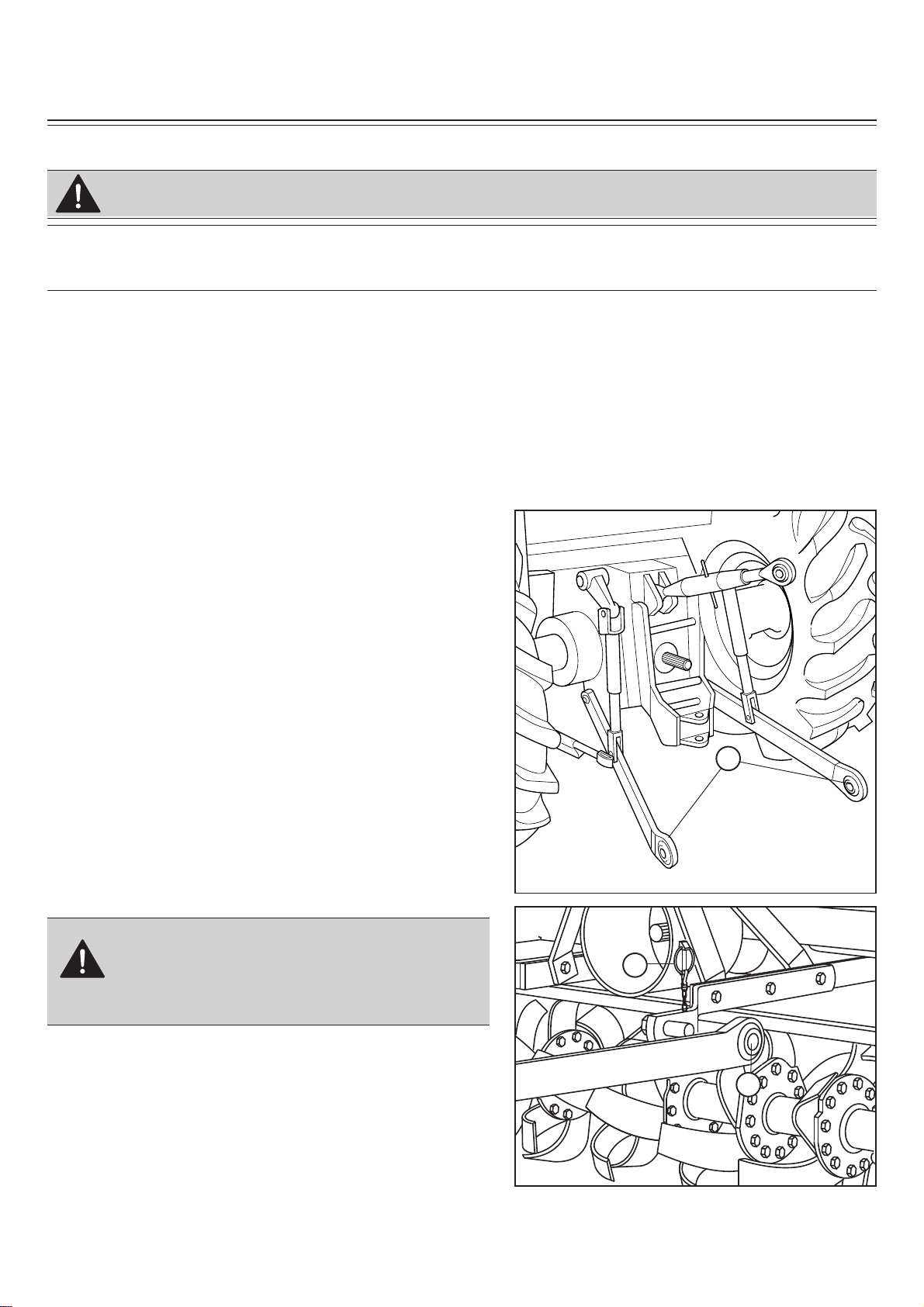
Installing tiller on tactor
1. Back tract o r int o position and align dr aft links (A) with
draft link bracke ts on tiller using t ract or r ockshaft control.
• STOP engine.
• LOCK park brake.
• FIRMLY block tiller on horizontal surface.
CAUTION: Before you work around hitch:
Locate driller pin in holes (B).
RT 1142-1149 model.
2. F aste n each draft link to draft link bracke ts with drilled
pins and quiklock pins (C).
A
C
B
Preparing the vehicle - Page 10
Page 11

INSTALLING
Locate driller pin in lower lift brackets holes
(B).
RT 1157-1165 model.
2. F aste n each draft link to draft link bracke ts with drilled
pins and quiklock pins (C).
C
B
Locate driller pin in holes (B).
RT 1265 model.
2. F aste n each draft link to draft link bracke ts with drilled
pins and quiklock pins (C).
Locate driller pin in top holes (D)
RT 1142-1149 model.
3. Install center link (F) on tiller and fasten with drilled
pin and quiklock pin (E).
C
B
F
D
E
Locate driller pin in top holes (D)
RT 1157-1165 and 1265 model.
3. Install center link (F) on tiller and fasten with drilled
pin and quiklock pin (E).
Preparing the vehicle - Page 11
D
E
F
Page 12

INSTALLING
4. Install PTO shaft to tractor.
IMPORTANT: Tiller MUST BE level front to rear.
• Engage the car dan shaft and check that it is perfectl y
locked on th e tr act o r PTO (G). Check that the guard
(H) is free to turn and fi x it with the relative latch.
5. Raise tiller.
6. Remove spring locking pin (K) from parking stand.
7. Slide parking stand (I) all the way up o n tiller br acke t
(J).
8. Fasten with spring locking pin (K).
9. Level tiller (See Leveling T ille r in th e Oper ating T ille r
section).
G
H
I
10. Adjust sway chains on tractor lower draft arms to
minimize side way.
PTO shaft
The PT O shaft, supp lied with the machine, is of standard
length.
Therefore it might be necessary to adapt the PT O shaft.
In that case, before doing anything, consult the Manufacturer for the eventual adaptation.
When th e PTO shaft is fully e xtended, th e two tubes must
overlap by at least 15 cm (A). When fully inserted, the
minimum play must be 4 cm (B).
J
K
A
CAUTION: If the implement is used on
another tractor, always check the that the
guards completely cover the rotating parts
of the PTO shaft.
Installing - Page 12
B
Page 13

INSTALLING
PTO shaft with shear pin (1142 model)
The shear pin, inserted in the PT O shaft, is equipped with
a safety bolt (A) that is set for an average force.
Whenever unduly resistant obstacles cause the bolt to
shear, it must be replaced by a new bolt.
PTO shaft with clutch (1149-1157-1165-1265
model)
The PTO shaft can be equipped with safety clutch to
protect the transmission components of th e machine from
stress and/or excessive overloads.
A
The tilt of the PTO shaft must not exceed 10 degrees.
The clutch is already pre-adjusted for average stress. If
it slips too easily (and overheats), it will be necessary to
evenly tighten all the nuts (D) that retain the spring.
The clutch disks must be changed if the clutch still slips
after all the nuts have been tightened.
If the clutch does not slip, evenly unscrew all the spring
fi xing nuts (D). Unscrew one turn at a time and check the
clutch after having wo rked about 300 meter s. R epeat the
operation if necessary , remembering t o unscrew one turn
at a time. If the clutch maintains a temperature of about
40-50°C (104-122°F) degrees during work, this means
that it has been correctly regulated.
IMPORTANT: Never fully tighten the nuts. This would
void the function of the springs and, subsequently,
of the clutch, thus damaging the transmission components.
D
NOTE: This inspection must be performed at the
beginning of each new season.
Installing - Page 13
Page 14

A
INSTALLING
Quick Coupler (optional)
1) Install hitch Quick Coupler (A) on the tractor (see
tractor operator manual).
2) Stop vehicle on a level surface, not on a slope, then
move the tractor back unt il the Quick Coupler (A) is
range with the (B) and (C) hitch points.
D
B
D
C
C
3) Raise the Quick Couple r (A) and make sure that tiller’ s
hitch is in the right position (E).
• STOP engine.
• LOCK park brake.
• FIRMLY block tiller on horizontal surface.
CAUTION: Before you work around hitch:
.
E
Park vehicle safely
• Stop vehicle on a level surface, not on a slope.
• Disengage PTO.
• Engage the park brake.
• STOP the engine.
• Remove the key.
• Before you leave the operator’s seat, wait for engine and all moving parts to STOP.
Stay clear of rotating drivelines
Entanglement in rotating driveline can cause serious injury or death:
• Wear close fi tting clothing.
• STOP the engine and be sure PTO driveline is stopped before getting near it.
Installing - Page 14
Page 15

REMOVING
Removing tiller
1. Raise tiller.
2. Put parking stand (A) in the DOWN position:
Install spring locking pin (C) in orde r to secure parking
stand (A) to the tiller bracket (B).
3. Lower tiller to the ground.
C
• STOP engine.
• LOCK park brake.
• FIRMLY block tiller on horizontal surface.
4. Disconnect driveline from tra ctor by pulling back on
5. Remove quik-lock pin (D) and drilled pin (E) from
NOTE: Put quik-lock pins and driller pins back into
6. Remov e dr aft links (J) from draft link brackets (G) by
NOTE: Put quik-lock pins and driller pins back into
7. Drive tractor forward slowly.
CAUTION: Before you work around hitch:
coupler to release it from the LOCKED position.
center link (F).
brackets on tiller for storage.
removing quiklock pins (H) and drilled pins (I).
brackets on tiller for storage.
A
B
RT 1142 - 1149
F
RT 1157 - 1165 and 1265
E
E
D
D
F
Removing tiller with Quick Coupler
1. Raise tiller.
2. Put parking stand (A) in the DOWN position:
Install spring locking pin (C) in orde r to secure parking
stand (A) to the tiller bracket (B).
3. Lower tiller to the ground.
4. Raise the two Quick Coupler lev ers (D) t o unlock tiller
(Quick Coupler fi gure, page 14).
5. Lower Quick Coupler until free from the tiller.
Removing - Page 15
G
H
J
I
Page 16

OPERATING
Operate safely
• Pr otect your hands whe n you inspect or unplug th e tiller . You may need g lov es or tools , such as a screw dri-
ver or scraper. Be sure hardware is tight. Repair or replace damaged, badly worn, or missing par ts. Be
sure guards and shie lds ar e in good condition and f aste ned in p lace . Make any necessary adjustments
before you operate.
• Clear work area of objects that you do not want tilled
into the ground or that might damage the tiller. Consider the tilling area and set up a safe tilling pattern. Do
not till under condition in which tract ion or stability is
doubtful. Keep people and pets out of the work area.
Stop machine if anyone enters the area.
• If you hit an object, stop the machine and inspect it.
Make re pai rs b efore you op erat e. Keep ma chi ne pro perly maintained and in good working order.
• DO NOT leave machine unattended when it is run-
ning.
• Only operate during daylight or with good artifi cial
light.
• DO NOT let anyone, ESPECIALLY CHILDREN, ride on
machine or vehicle. Riders are subject to injury such
as being thro wn off . Ride r s may also obst ru ct the operato r’ s view , resulting in the machine being ope rated in
an unsafe manner.
• DO NOT let children or an untrained person operate
machine.
• DO NOT wear radio or music headphones while ope-
rating the machine. Safe operation requires your full
attention.
It is absolutely forbidden to stand between the tractor and the implement when maneuve-
ring the lift control from the outside.
Operating - Page 16
Page 17

OPERATING
Wear appropriate clothing
• Wear close fi tting clothing and safely equipment appropriate for the job.
• Loud noise can cause impairment or loss of hearing, wear a suitable protective device such as ear-
plugs.
Stay clear of rotating drivelines
Entanglement in rotating driveline can cause serious injury or death:
• Wear close fi tting clothing
• Stop the engine and be sure PTO drivelines is stopped before getting near it.
• STOP engine.
• LOCK park brake.
• FIRMLY block tiller on horizontal surface.
CAUTION: Before you work around hitch:
Raising parking stand
1. Remove spring locking pin (C).
2. Slide parking stand (A) all th e way up on tiller brack e t
(B).
3. Fasten with spring locking pin (C).
Lowering parking stand
1. Remove spring locking pin (C).
2. Slide parking stand (A) and put down on tiller bracket
(B).
3. Install spring locking pin in order to secure parking
stand to the tiller bracket.
4. Fasten with spring locking pin (C).
A
B
C
Leveling attachments (side-to-side)
1. Start the engine. Raise the tiller.
2. Stop the engine. Lock the park brake.
CAUTION: DO NOT work under a raised
tiller unless it is safely supported.
Operating - Page 17
C
A
B
Page 18

OPERATING
Leveling tiller (front-to-rear)
1. Start the engine.
2. Lower the tiller to 25 mm (1 in.) off the ground.
3. Stop the engine.
4. Make sure the t op of the tiller is LEVEL, o r P ARAL-
LEL with the ground, front-to-rear.
5. Adjust level, if necessary. To adjust level:
a. Start the engine.
b. Lower the tiller to the ground.
c. Stop the engine.
d. Loosen jam nut (A).
• Shorten the center link (B) to lower the front of the
tiller.
• Lengthen the ce nter link (B) t o raise the f ro nt of the
tiller.
e. Tighten jam nut.
A
B
• STOP engine.
• LOCK park brake.
• FIRMLY block tiller on horizontal surface.
CAUTION: Before you work around hitch:
Adjusting skid shoes
Before adjusting skid shoes lift tiller, place tiller o n t op of
two wooden blocks underneath tiller rotor (see fi gure).
1. Raise tiller.
2. Place wooden blocks.
3. Lower tiller on wooden blocks.
4. Loosen pivot bolt (A) and (D).
5. Loosen adjusting bolt (B) and lock nut.
6. Adjust skid shoe (C) to desired position.
7. Tighten bolts (A), (B) and (D).
NOTE: Adjust both skid shoes to same depth.
A
D
B
C
6. Repeat above steps for the other skid shoe.
Adjusting leveling board
1. Install chain (A) in bracket (B).
Operating - Page 18
B
A
Page 19

OPERATING
2. Lower leveling board to top of ground (C):
• Tilled soil (D) will be fi ne and level.
• Tractor speed will determine size of clods (E).
C
3. Raise leveling board (C):
• Tilled soil (D) will be coarse and rough.
• Tractor speed will determine size of clods (E).
• STOP engine.
• LOCK park brake.
• FIRMLY block tiller on horizontal surface.
CAUTION: Before you work around hitch:
Adjustable offset
The tiller unit can be shifted sideways in relation to the
three-point hitch. This makes the implement extremely
versatile during the various working conditions.
Use of the hexagonal drive shaf t allows the tiller unit to
quickly slide, thus notably simplifyng the operation.
The following operations must be carried out:
RT 1142 - 1149
1. Thoroug ly clean the fr ame and relativ e guides to allow
the parts to work smoothly.
2. Loosen the bolts (A) that fi x the bracket and leave
these free.
3. Move the carriage to the position required and the
tighten the two carriage fi xing bolts.
E
D
C
E
D
RT 1142 - 1149
A
RT 1157 - 1165
1. Thoroug ly clean the fr ame and relativ e guides to allow
the parts to work smoothly.
2. Loosen the bolts (B) that fi x the bracket and leave
these free.
3. Move the carriage to the position required and the
tighten the two carriage fi xing bolts.
Operating - Page 19
RT 1157 - 1165
B
Page 20

OPERATING
Tilling tips
Before You till:
• Pick up rocks and foreign objects.
• Mow tall weeds and grass to keep them from wrapping around tines or tine shaft.
• Check tines. Loose, bent, broken, or missing tines reduce operating effi ciency. If necessary, replace
tines.
Test the soil by squeezing it in your hand. If soil forms a ball, it is too wet to till. If soil does not compress
easily or falls apart, it is ready to till.
DO NOT t ill when soil is wet. Wet soil will stick to the tines and tine shaf t. Wet soil will also dry out and
become hard, making it hard to work with during the growing season.
During tilling
CAUTION: Never lower tiller into the ground while the tractor is turning.
• DO NOT back up or make sharp turn with tiller in ground.
• Move PTO switch lever to ON when tiller is out of the ground. Move tractor for ward and lower tiller into
the ground.
• When you till hard ground or sod, till at a shallow depth on fi rst pass. Increase depth on each pass.
• When tilling on a hillside:
- Work up the the slope, if possible.
- If la teral work ca nno t be avoi ded , work from t he top to the b ottom in ord er to limit any terracing ef-
fect.
Replacement parts
See Service Dealer for original parts.
PART NUMBERS MAY CHANGE, use part number s listed at th e e nd of this manual when you orde r. If a
number changes, your dealer will have the latest number.
WHEN YOU ORDER PARTS, your Frontier Equipment dealer needs your machine serial number. This is
the number you have recorded in the INTRODUCTION section in the front of this manual.
Operating - Page 20
Page 21

SERVICE MACHINE SAFELY
Practice safe maintenance
• Understand service procedure before doing work. Keep area clean and dry.
• Ne ver lubricate , service, or adjust machine while it is moving . Keep saf ety devices in place and in wo rking
condition. Keep hardware tight.
• To prevent from getting caught, keep hands , feet, clothing, jewelry, and long hair aw ay from any moving
parts.
• Before servicing machine, lo w e r it t o the g r ound. Dise ngag e all po wer and stop the v e hicle e ngine . Lock
vehicle park brake and remove the key.
• Securely support any machine elements that must be raised for maintenance.
• Keep all parts in good condition and properly installed. Fix damage immediatel y . Replace w orn or br oken
parts. Remove any buildup of grease, oil, or debris.
• Unauthorized modifi cations to the machine may impair its function and safety.
Wear appropriate clothing
• Wear close fi tting clothing and safety equipment appropriate for the job.
• Loud noise can cause impairment or loss of hearing, wear a suitable protective device such as ear-
plugs.
• Do not wear radio or music headphones while servicing the machine. Safe servicing requires your full
attention.
Stay clear of rotating drivelines
Entanglement in rotating driveline can cause serious injury or death:
• Stop the engine and be sure PTO drivelines is stopped before getting near it.
Service Machine Safely - Page 21
Page 22

SERVICE LUBRICATION
Service lubrication
WARNING: • Firmly block tiller on horizontal surface.
• Always keep oils and greases well away from children’s reach.
• Always thoroughly read the warnings and precautions indicated on the
containers. Avoid contact with the skin.
• Always thoroughly and fully wash after use. The utilized oils should be
treated in compliance with the current anti-pollution laws.
Every 8 work hours
• Grease the cardan shaft cross journals (A) and (B).
• Check that the bolts fi xing the hoe blades (M) are well
tightened.
• Grease the rotor spindles (D).
Every 50 work hours (see page 23 for E, F, G, I and
H)
• Check the level of the oil in the g earbox or in the reduction
unit (E) and top off to the level mark on the rod as necessary.
• Transmission chain: check the level of the oil in the side
casing of the transmission unit, unscrew the level plug (G)
and check that oil fl ows out.
Add oil through the fi ll plug (F) if necessary. It should fl ow
from the level plug (G).
Every 400 work hours
• Change the oil in the reduction unit and transmission cas-
ing by completely draining off the old oil through the drain
plug under the r eduction unit and thr ough the t ransmissio n
drain plug.
• When this operation is carried out, it is also advisable to
demount and clean the clutch disks (C) (if the car dan shaft
has a clutch). Check the tightening of the clutch springs.
Every 1000 work hours
Greasing chain (RT 1142 - 1149)
1. Install park stand.
2. Lower tiller to the ground.
3. Remove all bolts and nuts (A).
4. Remove cover (B).
5. Put a he av y coat of m oly hi gh t empera ture extreme p res-
sure grease GR MU EP2 or an equivalent on chain and
sprockets.
C
A
A
B
A
A
B
Service Lubrication - Page 22
Page 23

SERVICE LUBRICATION
Greasing and lubricant points
RT 1142 - 1149 model
D) Rotor spindle lubricator
E) Reduction unit oil plug: Qty. 0.5 lt
(0.13 US gal.)
M) Hoe blades fi xing bolts
N) Greasing chain (see Service lubrication:
Every 1000 working hours):
Qty. 0.5 Kg (1.1 lb)
Greasing and lubricant points
RT 1157 - 1165 and 1265 model
D) Rotor spindle lubricator
E) Reduction unit oil plug
F) Transmission oil fi ll plug
G) Transmission oil drain plug
M) Hoe blades fi xing bolts
E
N
D
M
E
OIL QUANTITY : lt (US gal.)
1157 1265
1165
Reduction unit oil (E) 1 (0.26) 0.75 (0.2)
Transmission oil fill chain (F) 1 (0.26) 0.75 (0.2)
Lubricants
• It is advisable to use SAE 85W/140 OIL
or equiv alent for th e reduction unit (or g ear
box) and side transmission.
• It is advisable to use GR MU EP 2 GREASE
or equivalent for all greasing points.
F
D
M
G
Service Lubrication - Page 23
Page 24

SERVICE
Chain stretcher
RT 1142-1149 and RT 1157-1165 model
Automatic chain stretcher regulates the tension of the
drive chain.
RT 1265 model
A special mechanical chain stretcher regulates the tension of the dri v e chain (A). If there is too much play , then
you must loosen lock nut (B) and tighten screw (C) as
much as necessary.
Then tighten lock nut which locks the adjustment screw
into place.
Service intervals
Every 50 working hours:
• Tighten mast brackets bolts.
• Tighten skid shoe bolts.
B
C
A
Bolts tightening torques - settings given in Nm (lb-ft)
Fine pitch screws
6.6 8.8 10.9 12.9
M8 x 1 15 (11) 26 (19) 36 (26.5) 44 (32.5)
M10 x 1.25 30 (22) 52 (38) 74 (54) 88 (65)
M12 x 1.25 51 (37.5) 91 (67) 127 (94) 153 (113)
M14 x 1.5 81 (60) 143 (105) 201 (148) 241 (178)
M16 x 1.5 120 (88) 214 (158) 301 (222) 361 (266)
M18 x 1.5 173 (127) 308 (227) 433 (319) 520 (384)
M20 x 1.5 242 (178) 431 (318) 606 (447) 727 (536)
M22 x 1.5 321 (237) 571 (421) 803 (592) 964 (711)
M24 x 2 411 (303) 731 (539) 1028 (758) 1234 (910)
M27 x 2 601 (443) 1070 (790) 1504 (1110) 1806 (1333)
M30 x 2 832 (614) 1480 (1090) 2081 (1535) 2498 (1843
CLASS
Replacing tines
CAUTION: To prevent injury: Wear heavy gloves when replacing tines.
)
To get the best performance from your tiller:
• Replace badly bent, worn, or broken tines immediatly.
• Replace worn or broken hardware (see your Frontier dealer for correct hardware).
• MAKE SURE to replace tines on ONE spindle at time to keep spiral tine pattern.
• Tine cutting edge MUST BE facing forward in direction of tine rotation.
Service - Page 24
Page 25

SERVICE
CAUTION: Make sure you block tiller before doing any service on the tiller.
• STOP engine.
• LOCK park brake.
• FIRMLY block tiller on horizontal surface.
Tines can be changed with the t iller mounted on tractor. Make sure you block the tiller before doing any
service on the tiller.
Tines
Before replacing tines make sure the tiller is fi rmly blocked.
The tines with which the rotary tiller is equipped can work so ils of normal co nf ormation. Ch eck the deg r ee
of wear and co ndition of the tines each day. If the blades should accide ntall y be nd (o r br eak) during w ork,
they must be immediately replaced.
First - Identify tines:
Remember to mount the new tine in exactl y the same position as the old one (A). If several tines must be
replaced, it is advisable to remove and assemble one tine at a time in order to prevent positioning errors.
The tillers are normally equipped with 4 blades per fl ange.
Second - Install New Tines:
1. Raise tiller with a safe lifting device.
1. Put safety stands or blocks under tiller.
3. Stand facing rear of tiller and study placement of
tines.
4. Remove four bolts, lock washers, and nuts (C).
NOTE: Make sure to replace tines on ONE spindle at
a time to keep spiral tine pattern.
5. Remove left-hand tine (A) and right-hand tine (B).
6. Install new tines and fasten with bolts, lock washers,
and nuts (removed above).
NOTE: Two bolts go in from each side. Refer to sketch
at right.
7. Tighten bolts.
CAUTION: The heads of the bolts fi xing the
hoe blades in place must be on the side of
the hoe blades themselves, while the nut
with relative washer must be on the fl ange
side (B). Tighten bolts to 91 Nm (67 lb-ft).
A
B
C
Rear
Front
Service - Page 25
Page 26

TROUBLESHOOTING
Using troubleshooting chart
If you are experiencing a problem that is not listed in this chart, see your Frontier dealer for service.
When y ou hav e checked all th e possible causes listed and you are still e xperiencing th e problem, see your
Frontier dealer.
IF CHECK
EXCESSIVE TINE WEAR Replace loose or bent tine.
Replace tine when worn to a point.
TILLER BUMPING ON GROUND Obstacles entangled in tines.
Blades incorrectly mounted with no tine spiral effect.
Tines fi tted with blunt edge leading.
Broken tines.
INSUFFICIENT DEPTH OBTAINED Adjust depth control skids.
Insuffi cient power - use lower tractor speed.
Chain cover on hard soil - further passes required.
Blades rolling over ground - use lower tractor speed.
Adjust depth control on tractor.
TILLED SOIL TOO FINE Raise leveling board.
Use a faster tractor ground speed.
TILLED SOIL TOO COARSE Lower leveling board.
Use lower tractor speed.
Wait until soil is drier.
TINES BALLING UP WITH SOIL Raise leveling board.
Decrease tractor speed.
Ground too sticky for working.
CUTTING TOO DEEP ON ONE SIDE Tiller not level:
• Level tiller.
• Adjust depth control skid.
NOT OVERLAPPING Drive closer to last run.
Start in center and go around clockwise.
(Tilled soil to the right of the operator.)
Troubleshooting - Page 26
Page 27

STORING MACHINE
Storing tiller
CAUTION: Before you work around hitch:
• STOP engine.
• LOCK park brake.
• FIRMLY block tiller on horizontal surface.
1. Put parking stand in the DOWN position (See Lowering Parking Stand in the Operating Tiller section).
2. Disconnect tiller from tractor (See Removing section).
3. Clean tiller and inside of driveline shield.
4. Repair or replace badly worn or damaged parts.
5. Tighten hardware.
6. Lubricate tiller.
7. Grease chain (See Greasing Chain in the Service - Lubrication section).
8. Store tiller in a dry place on a hard level surface with the parking stand in the LOWERED position.
9. If you store tiller outside, put a waterproof cover on it.
Removing tiller from storage
1. Install tiller on the tractor.
Storing Machine - Page 27
Page 28

ASSEMBLY
RT 1142 - 1149
CAUTION: FIRMLY block tiller on horizontal surface.
Installing mast braces (PHASE 1)
1) Install spacer (D), bolt (F) and nut (B) on mast braces (A and G).
Do not tighten bolts and nuts at this time.
Installing parking stand (PHASE 2, operation 1)
2) Put parking stand (O) and fasten bolts (N) and nuts (M).
Tighten lock nuts to the requested tightening torque.
Installing mast braces on tiller (PHASE 2, operation 2)
3) Install mast assembly on tiller frame and t ighten (see below fi gure). Bolts (I) and nuts (L) to the the
requested tightening torque.
• Fine Pitch screws: M12 x 1.25
• Class: 8.8
• Bolts tightening torques: 91 Nm (67 lb-ft).
Assembly - Page 28
Page 29

ASSEMBLY
RT 1142 - 1149
A
F
PHASE 1
D
B
G
PHASE 2
OPERATION 2
H
I
L
M
N
O
OPERATION 1
Assembly - Page 29
Page 30

ASSEMBLY
RT 1157 - 1165
CAUTION: FIRMLY block tiller on horizontal surface.
Installing mast braces (PHASE 1)
1) Install spacers (D), bolts (E) and nuts (C) on mast braces (I, M) and adaptation plates (A,B)
Do not tighten bolts and nuts at this time.
Installing parking stand (PHASE 2, operation 1)
3) Put parking stand (N) and fasten bolts (O) and nuts (P).
Tighten lock nuts to the requested tightening torque.
Installing draft link brackets (PHASE 2, operation 2)
NOTE: big holes on brackets should be on bottom (see fi gure)
4) Put each link bracket (U) and (T) on tool bar and fasten bolts and nuts (V, Z).
Do not tighten bolts and nuts at this time.
5) Measure distance between dr aft link brackets (U). Fo r the corr ect measurement of th e brackets , center ed
with gearbox, see the table.
6) Tighten lock bolts (V) and nuts (Z) to secure draft link brackets to tool bar.
• Fine Pitch screws: M16 x 1.5
• Class: 8.8
• Screw tightening torques: 214 Nm (158 lb-ft).
Installing mast braces on tiller (PHASE 2, operation 3)
7) Install mast assembly on tiller frame and tighten bolts (R) and nuts (S) to the the requested tightening
torque.
• Fine Pitch screws: M12 x 1.25
• Class: 8.8
• Screw tightening torques: 91 Nm (67 lb-ft).
8) Tighten bolt and nut (E and C) to the requested tightening torque: 214 Nm (158 lb-ft).
Assembly - Page 30
Page 31

ASSEMBLY
RT 1157 - 1165
PHASE 1
D
E
C
A
Q
S
M
PHASE 2
R
B
I
OPERATION 3
OPERATION 2
Z
T
V
U
N
Assembly - Page 31
P
O
OPERATION 1
Page 32

ASSEMBLY
RT 1265
CAUTION: FIRMLY block tiller on horizontal surface.
Installing mast braces (PHASE 1)
1) Install spacer (D), bolt (E) and nut (C) on mast braces (I, M).
Do not tighten bolts and nuts at this time.
2) Install front and rear plates (B, H) with bolts and nuts (A, F, L, G) on mast braces.
Do not tighten bolts and nuts at this time.
Installing parking stand (PHASE 2, operation 1)
3) Put parking stand (N) and fasten bolts (O) and nuts (P).
Tighten lock nuts to the requested tightening torque.
Installing draft link brackets (PHASE 2, operation 2)
NOTE: big holes on brackets should be on bottom (see fi gure)
4) Put each link brackets (U) and (T) on tool bar and fasten bolts and nuts (V, Z).
Do not tighten bolts and nuts at this time.
5) Measure distance between dr aft, link brackets (U). F or the corr ect measurement of th e brackets , center ed
with gearbox, see the table.
6) Tighten lock bolts (V) and nuts (Z) to secure draft link brackets to tool bar.
• Fine Pitch screws: M16 x 1.5
• Class: 8.8
• Screw tightening torques: 214 Nm (158 lb-ft).
Installing mast braces on tiller (PHASE 2, operation 3)
7) Install mast assembly on tiller frame and tighten bolts (R) and nuts (S) to the the requested tightening
torque.
• Fine Pitch screws: M12 x 1.25
• Class: 8.8
• Screw tightening torques: 91 Nm (67 lb-ft).
8) Tighten all bolts and nuts (A, L, F and G).
9) Tighten bolt and nut (E and C) to the requested tightening torque: 214 Nm (158 lb-ft).
Assembly - Page 32
Page 33

D
C
M
B
A
ASSEMBLY
RT 1265
PHASE 1
E
F
G
H
I
L
Q
S
PHASE 2
OPERATION 3
R
Z
T
U
V
OPERATION 2
P
Assembly - Page 33
O
N
OPERATION 1
Page 34

ASSEMBLY / SPARE PARTS
Installing driveline on tiller
NOTE: Shield removed for clarity ONLY. ALWAYS
keep shield in place.
1. P ull coupler back and slide dri veline o n driv eshaft until
coupler LOCKS in place.
NOTE: You should hear a clicking sound when driveline is properly installed.
Spare parts
Spare parts should be ordered from your Dealer and should always include the following indications:
• Type, model and serial number of the machine. These data are punched o n the data plate with which
every implement is equipped.
• Code number of the required spare part. This will be found in the spare parts catalogue.
• Description of the part and required quantity.
• Table number.
NOTE: The terms right or left indicated in the descriptions refer to the implement when viewed
from the rear side.
Assembly - Page 34
Page 35

Page 36

Part N°. F07010181
 Loading...