

Page 1
OPERA T OR'S MANU A L
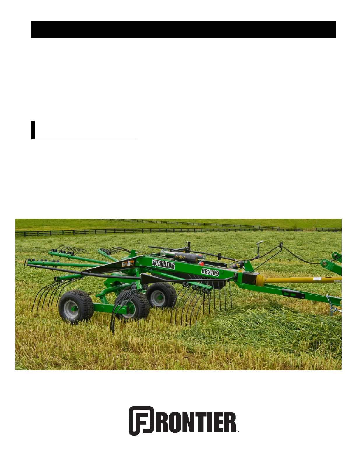
ROTARY RAKE
RR2109
5PQ990104 (08/28/2012)
Page 2

To the Owner;
Thank-You for choosing a quality product from Frontier Equipment. We strive
to give you the best equipment and the best level of service of any company.
With a little care and maintenance this machine will do your work for you for
many years. In this manual, we make an effort to get you better acquainted
with the machine so you can achieve maximum performance. We design
and build all of our equipment with the end user in mind so we welcome any
suggestions or ideas for improvement. Please note that it is within our rights
to make changes or improvements to our equipment without updating the
equipment that was manufactured before the change took place.
Please take a few minutes to ll out the area below. This information will be
valuable to you when ordering parts or requesting service from your dealer.
Dealer Name:_____________________________
Dealer Phone Number:______________________
Service Manager/Technician:_________________
Model# and Description:_____________________
Serial Number:____________________________
Date of Purchase:__________________________
Page 3

TABLE OF CONTENTS
Introduction ……………………………………………………………… 2
Rake Serial Number ………………………..……………… 2
Specications ………………………………………………… 2
Safety ………………………………………………………...……………… 3
Power Source Safety ………………………………………… 3
Safety Decals …………………….…………..……………… 4
Driveline Safety …………………….…………..…………..… 5
Dealer Setup ……………………………………………..……………… 6
Hitching ……………………………………………………..……………… 8
Tractor Requirements ……………………….……………… 8
Hitching ………………………………………..……………… 8
Transporting ……………………………………………………………… 10
Field Transport ……………………………………………… 10
Road Transport ……………………………………………… 10
Height and Level Adjustment ………………………....………… 11
Height Adjustment ………………………………………..… 11
Leveling the Rake ………………………………………… 11
Hay Curtain Adjustments ………………………………………… 12
Operating ……………………………………………………………….… 13
Field Dangers …………………………………………….… 13
Lubrication …………………………………………………………….… 14
Gearbox Lubrication ……………………………………..… 14
PTO Lubrication …………………………………………..… 15
General Lubrication ……………………………………...… 15
Maintenance …………………………………………………………..… 16
Storing your Rake …………………………………………………… 16
Torque Specications ……………………………………………… 17
Standard Torque Chart …………………………………..… 17
Metric Torque Chart ………………………………………… 18
Warranty ………………………………………………………………...… 19
Illustrated Parts Breakdowns …...……………………………...… 20
Tongue & Main Frame …….……………………………… 21
Guards …………………..…………………………………… 22
Gearbox & Tine Arm …..…………………………………… 23
Axle Assembly ……………………………………………… 24
Rotary Gearbox …….……………………………………… 25
PTO Shaft ……………...…………………………………… 26
Decals & Reectors …..…………………………………… 27
1
Page 4
INTRODUCTION
Thank-You for choosing the Frontier Rotary Rake. Your rake is the result of years of research
and development work. This Operator’s Manual will familiarize the operator with the safety and
operation of the machine. Included are complete instructions for assembly, operation, lubrication,
and maintenance procedures. Understanding and following these procedures will result in years
of maximum performance from your Frontier Rake.
Read entire manual before operating. Failure to follow the instructions outlined in this
manual may result in personal injury and/or damaged equipment, and could void the warranty.
Rake Serial Number
The rake’s serial number can be found near the front on the main frame of the rake. Please use
this number when requesting service, seeking information, or ordering parts. For the operator’s
convenience, space to record the serial number, model number, purchase date, and dealer has
been provided inside the front cover of this manual.
All pictures and instructions in this manual assume that the right and left side
of the machine are that of someone standing behind the rake facing forward.
Specications
Specications RR2211 RR2109
Working Width 13' (4.3m) 10' 8" (3.2m)
Raking Width 11' (3.3m) 9' (2.7m)
Transport Width 59" (1.5m) 9' 4" (2.8m)
Gear Box Enclosed Oil Bath
Gear Reduction 9.7 to 1
Tine Arms 11 9
Double Tines per Arm 4 3
PTO/HP Required 40 HP - 540 RPM 30 HP - 540 RPM
Direction of Raking Action Left
Hydraulic Requirement 1200 psi
Weight 1550 lbs. 1050 lbs.
Tandem Axle Beam Standard
Tires 18.5 x 8 Flotation Tires on 4-Bolt Painted Wheels
2
Page 5

SAFETY
This symbol precedes specic safety instructions throughout this manual. When reading
the manual pay close attention to the information that follows this symbol.
FAILURE TO FOLLOW INSTRUCTIONS IN THIS MANUAL COULD RESULT IN PERSONAL
INJURY OR DEATH. READ ENTIRE MANUAL BEFORE OPERATING ROTARY RAKE.
Keep hands, feet and clothing away from the machine’s input power take-off (PTO) and any
other moving parts until the machine has been shut down and the power source has been locked
out. (Refer to Power Source Safety)
Do not adjust, unclog, lubricate, or service the machine until it has been shut down and the
power source has been locked out. (Refer to Power Source Safety)
Do not lubricate or adjust the machine while it is in motion.
Support the rake securely while working under it.
Do not stand between the tractor and the rake while attaching or detaching the rake unless the
tractor engine is shut off and the parking brake has been set.
Be certain all bystanders and animals are a safe distance away from the rake before raising or
lowering it. Never allow anyone to ride on the rake or the tractor.
When transporting, never exceed a speed of 20 MPH (32kkm/hr) and avoid sudden turns which
may compromise the operator’s control of the tractor.
Be constantly aware of the location of the ends of the rake to avoid collision with other objects.
When moving the rake on public roads use the proper reectors, lights, and slow moving vehicle
signs required by local government agencies.
Power Source Safety
Do not use a power take-off (PTO) shaft without a rotating shield in good working order. Make
sure drive system safety shields are in place for both the power source and the rake.
The rake input PTO must be securely attached to both the power source and the input shaft.
Do not overextend the input PTO shaft.
Make sure PTO is disengaged before starting power source.
PTO shield chains must be attached to the tractor and the rake to keep the shield from rotating.
3
Page 6
SAFETY CONT’D
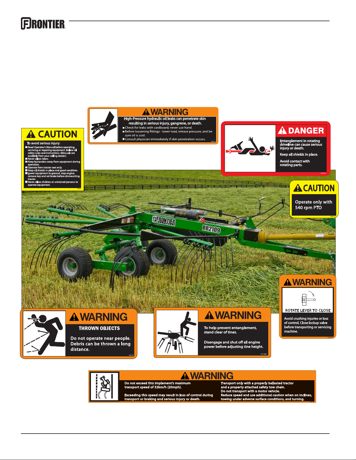
Safety Decals
Decals and reectors are for the protection of yourself and others. If they are missing,
faded, or not readable, get replacements from your dealer immediately.
4
Page 7
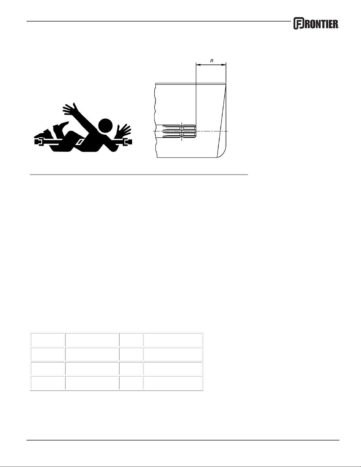
Stay Clear of Rotating Drivelines
master shield shall overlap the end of the splined shaft and the added adaptor
TS1644-UN-22AUG95 H96219-UN-29APR10
Entanglement in rotating driveline can cause serious injury or death.
Keep tractor master shield and driveline shields in place at all times. Make
sure rotating shields turn freely.
Wear close fitting clothing. Stop the engine and be sure that PTO driveline
is stopped before making adjustments, connections, or cleaning out PTO
driven equipment.
Do not install any adapter device between the tractor and the primary
implement PTO drive shaft that will allow a 1000 rpm tractor shaft to power
a 540 rpm implement at speeds higher than 540 rpm.
Do not install any adapter device that results in a portion of the rotating
implement shaft, tractor shaft, or the adapter to be unguarded. The tractor
device as outlined in the table.
PTO Type
1 35 mm (1.378 in.)
Diameter Splines n ± 5 mm (0.20 in.)
6 85 mm (3.35 in.)
2 35 mm (1.378 in.) 21 85 mm (3.35 in.)
3 45 mm (1.772 in.) 20 100 mm (4.00 in.)
5
Page 8
DEALER SETUP
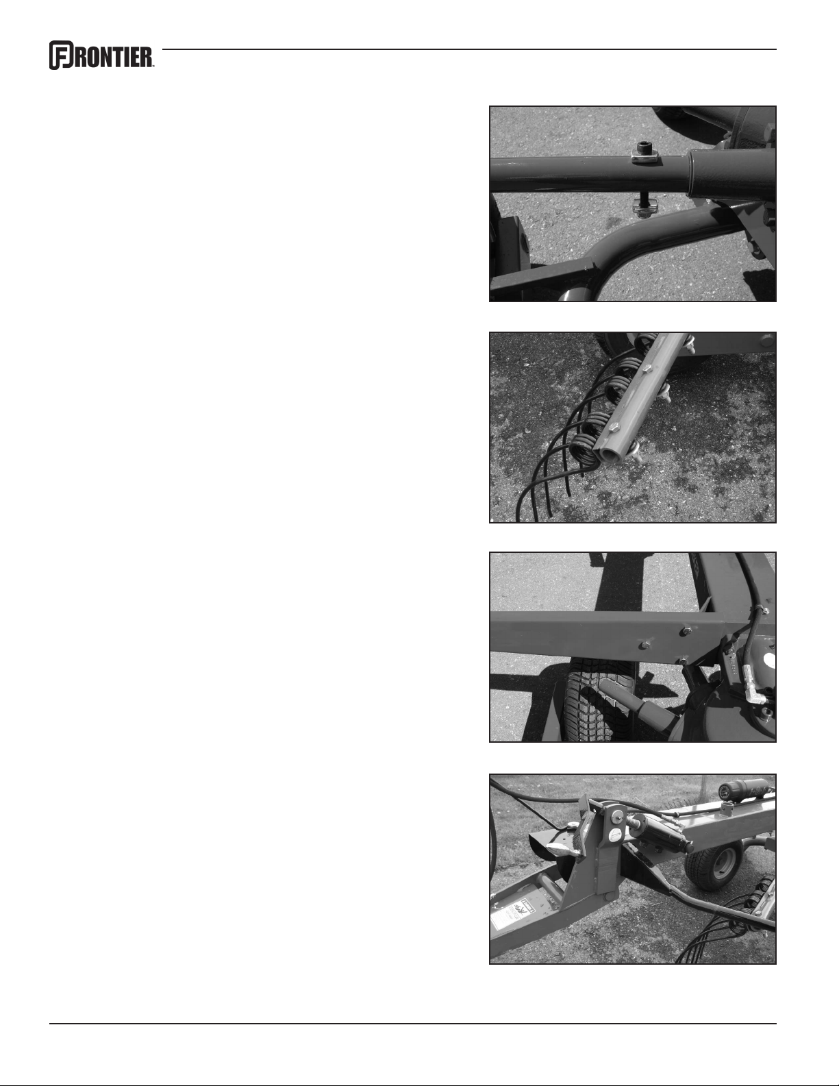
Tine Arms
Remove the rubber cap from the gearbox shaft. Slide
the tine arm onto the shaft. Line up the hole and insert the M10 metric socket head bolt. Place one of
the cupped washers on either side of the tine arm and
tighten the locknut. Repeat for all 9 arms.
Tines
Attach three tines to each arm using the 1/2 x 3-1/4
Grade 8 bolts. Insert bolt from the top and clamp the
tine in place with the 1/2” heavy washer and locknut.
Torque to 60-65 ft.-lbs.
Guard Support Arms
Attach the guard support arms to both sides of the rake
using the 1/2” bolts. NOTE: The guard arm with the
curtain mount tube is for the left side of the rake.
Guards, Front
Attach the front half of the guard to the main frame using the 3/8 x 1 bolts, lockwashers & nuts. Repeat both
sides.
6
Page 9
DEALER SETUP CONT’D
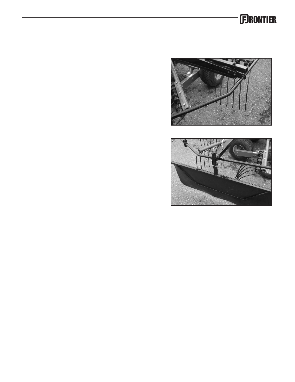
Guards, Rear
Attach the rear half of the guard to the guard support
arm using the 5/16 bolts, lockwashers & nuts. A lso attach to the front guard using 3/8 hardware.
Hay Curtain
Slide the curtain mount tube into the tube on the guard
arm and lock with the locking handle. Attach the curtain and select the desired height. Insert locking pin to
secure.
Note to customer: This setup for the RR2109 is usually done by the dealer, however, the arms and guards
can easily be removed for winter storage if you prefer.
7
Page 10
HITCHING
Tractor Requirements
The Frontier Rotary Rake is designed to be used with a tractor having a 540 RPM PTO. The
hitch pin hole on the tractor should be 14” (35cm) from the rear of the groove in the PTO output
shaft. (See illustration below)
NOTE: If the hitch pin hole is located well behind the tractor tires there is the potential of making
a sharp enough turn to damage the rake PTO shaft.
Tractor PTO
Shaft
Rake Driveline
Tractor Drawbar
14”
Center Line of Hitch
Pin Hole
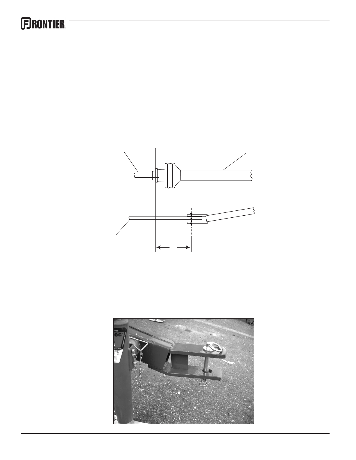
Hitching
Align the hole in the tractor draw bar with the hole in the rake tongue and insert an approved
hitch pin. Lock hitch pin with a safety clip to insure that it cannot work its way out. Attach the
safety chain to the tractor.
8
Page 11

HITCHING, CONT’D
With PTO shaft connected to the rake, slide shaft safety collar back and slide the tractor side of
the PTO shaft onto the tractor drive shaft. Release the shaft safety collar. Insure that the PTO
shaft is securely locked onto the tractor drive shaft. Fold the PTO stand down onto the frame to
avoid damaging the PTO shaft shielding. (See illustration below)
Connect the rake hydraulic line to the tractor implement hydraulic output.
Crank the rake jack off of the ground and remove the locking pin. Pull the jack off of the mount,
place in storage position on the main frame, and reinsert locking pin. (See illustration below)
The jack can also be stored on the hitch beam by simply giving it a quarter turn. This position
is not recommended in the eld though as it increases the risk of damaging the jack with the
tractor wheel when turning.
9
Page 12

TRANSPORTING
Field Transport
• Make sure that the rake is raised into the transport position.
• Never allow anyone to ride on the rake or the tractor other than the operator.
• Avoid tight turns to reduce the possibility of loss of control or PTO shaft damage.
• Remain fully aware of the width of the rake in relation to the objects you are passing, either
stationary or moving.
• Never travel at speeds over 10 MPH (16km/hr.) in the eld.
Road Transport
• Adhere to all suggestions for transport in the eld listed above.
• Follow all local regulations for moving agricultural equipment on public roads, especially those
related to reectors, SMV (slow moving vehicle) symbols and safety markers.
• Never travel at speeds over 20 MPH (32km/hr.) on the road.
10
Page 13

HEIGHT AND LEVEL ADJUSTMENT
Height Adjustment
The RR2109 Rake has an adjustment screw for the rear height adjustment. (See illustration
below) Turn clockwise to raise or counterclockwise to lower the rake. With the rake setting on
level ground, set the height so that the tips of the tines are 1” (25mm) from the ground. This
setting will offer the best performance in most eld and crop conditions, however, in uneven
or rocky areas we recommend setting the tines higher off the ground to reduce tine wear and
stress. There is no advantage to having the tines actually hit the ground. Hitting the ground will
cause unnecessary wear on the tines, and will cause the hay to become contaminated with
dust, resulting in premature wear of other processing equipment. An occasional adjustment will
also be necessary to account for normal tine wear.
Leveling the Rake
Your rake is also equipped with a leveling cylinder. This is on the front of the main frame and
can be adjusted quickly at any time to accommodate different draw bar heights. Simply turn the
handle clockwise to raise or counter-clockwise to lower the front of the rake. NOTE: You will
get the best performance with the front of the rake slightly lower than the rear.
11
Page 14

HAY CURTAIN ADJUSTMENTS
Whenever desired, the hay curtain on your hay rake can easily be adjusted to accommodate
your requirements. The hay curtain adjustment determines the width of the windrow, and is
used when turning a windrow or removed when combining windrows.
The working width of your swath is adjusted by positioning the hay curtain. To change the curtain position, turn the L-shaped rod (1) on the curtain mounting tube. Loosen by turning counter clockwise and tighten by turning clockwise until tight. (Do not overtighten)
The height of the hay curtain is adjusted by removing the stop pins (2) on the curtain frame
and raising or lowering the curtain to the desired height. We recommend setting it so the bottom of the curtain just touches the cut plant.
When combining windrows the curtain may be turned upside down or eliminated completely.
1 2
12
Page 15

OPERATING
Having made adjustments (where necessary) described in the previous sections, drive the
tractor to where you will begin raking. With the tractor standing still, lower the rake to it’s
operating position. Engage the tractor’s PTO at a low RPM, (this is especially important on a
tractor with an electric clutch) and without getting off the tractor seat, visually determine that
the rake is properly adjusted. If further adjustments are required, disengage the PTO and
stop the tractor’s engine and adjust where needed.
When ready, increase PTO speed to the desired RPM and engage the tractor’s forward
gear. Remember, ground speed and PTO speed, along with the proper adjustment for
height and level, will play a large role in making a clean sweep and a nice even windrow. 6
MPH ground speed and 350 PTO RPMs is the ideal combination for uffy windrows. Adhere
to all safety requirements as listed previously for eld operation.
Always operate the rake at the lowest RPM possible that allows you to rake cleanly at your
chosen ground speed. Higher speeds result in more leaf loss and lower quality hay, especially if you are raking dry hay. Higher speeds will also cause more wear on the rake.
When nished, reduce PTO speed before disengaging. Disengage PTO and raise rake into
transport position before leaving eld.
Requirements will change according to eld and crop conditions.
Field Dangers
While operating the rake you must constantly be aware of all your surroundings. The folddown guards are designed for human safety and will not withstand a collision with a stationary object such as a fence post or an electric pole. If such a collision does occur and you
cannot stop before the tine arms hit the obstacle, the safety slip clutch on the PTO shaft will
automatically engage and protect the gearbox from any serious damage. The slip clutch will
not engage fast enough to protect the tine arms.
The rake is also equipped with an anti rollover system for the axle tandem walking beams.
This is a safety feature that will keep the axle tandems from going over center and ipping
up into the tine arms when accidently driving over a washout, sink hole, or animal den. However, this is no excuse for careless driving, as other damage can occur when the wheels hit
a rut or a hole.
13
Page 16

LUBRICATION
It is extremely important to keep your rake properly lubricated at all times. Failure to do so will
greatly decrease the performance and the life of the machine.
Never lubricate or perform any maintenance, adjustments or repairs with the machine running.
The PTO must be disengaged and the tractor’s engine must be shut off.
With a clean cloth wipe off both the grease tting and the tip of the grease gun. This will eliminate any chance of dirt or dust particles getting inside and damaging the bearings.
Do not overgrease the ange bearings. Overgreasing could rupture the seals exposing the
bearing to a lot of dust particles. Roller bearings are sealed and are generally maintenance
free. The friction bearing points cannot be overgreased.
Gearbox Lubrication
The oil level in the gearbox can be checked by removing the check plug on the side of the
gearbox (1) and using a straw to insure that the oil level is near the bottom of the plug hole. If
oil needs to be added, use SAE 85W140 Gear Lube and ll using the plug located on the top of
the gear box (2).
1
2
3
We recommend changing the oil after every 200 hours of use. To do this, remove the plug at
the bottom of the gear box (3) and drain the oil into a container for proper disposal. Always follow local guidelines for disposal of waste oil in an environmentally appropriate manner. Never
drain waste oil directly onto the ground.
14
Page 17

LUBRICATION
PTO Lubrication
There are grease ttings on both the tractor end and the rake end of the PTO shaft. Grease
these after every 8 hours of operation. Use a high quality lithium grease.
General Lubrication
All other grease ttings should be lubricated after every 50 hours of operation. Use a high quality gear grease for the grease ttings on top of the gearbox. For all other bearings, joints, and
pivot points, use either a lithium or a gear grease. In dry, dusty conditions it may be necessary
to grease more than every 50 hours.
15
Page 18

MAINTENANCE
Check and replace any safety decals that are damaged or missing.
After rst use of the rake, we recommend a thorough inspection of all bolts and nuts. Retighten any loose hardware and check periodically thereafter.
Check the air pressure of the tires. They should be inated to approx. 20 psi.
Inspect the tines and replace any broken, missing, or bent tines.
Visually inspect condition of the hay curtain. Replace if necessary.
Periodically pressure wash your equipment and touch up any scratches with high quality rust
resistant paint.
Apply a light weight oil to all moving parts not specied in other lubrication instructions in this
manual.
STORING YOUR RAKE
Before winter storage, perform all lubrication and other maintenance procedures as previously described.
Store in a dry, covered place with the rake lowered into the raking position. Storing in the
raised (transport) position exposes the cylinder rod to dust and other elements that could
cause it to rust.
16
Page 19

TORQUE SPECIFICATIONS
The torque chart below lists the standard torque values for all attachment hardware on the
rake unless otherwise specied in this manual.
Standard Torque Chart
GRADE 5 BOLTS GRADE 8 BOLTS
BOLT SIZE
1/4 20 8 6 12 9
1/4 28 10 7 14 10
5/16 20 17 13 24 18
5/16 24 19 14 27 20
3/8 16 30 23 45 35
3/8 24 35 25 50 35
7/16 14 50 35 70 50
7/16 20 55 40 80 60
1/2/2 13 75 55 110 80
1/2/2 20 85 65 120 90
9/16 12 110 80 150 110
9/16 18 120 90 170 130
5/8 11 150 110 210 160
5/8 18 170 130 240 180
3/4 10 260 200 380 280
3/4 16 300 220 420 310
7/8 9 430 320 600 450
7/8 14 470 350 670 500
1-8 640 480 910 680
1-14 720 540 1,020 760
TORQUE (DRY)
FT.LBS.
LUBRICATED
FT.LBS.
TORQUE (DRY)
FT.LBS.
LUBRICATED
FT.LBS.
17
Page 20

TORQUE SPECIFICATIONS
BOLT SIZE & PITCH CLASS PLATED UNPLATED PLATED UNPLATED
M4 x .70 8.8 3.10 2.20 2.30 1.65
M5 x .80 8.8 6.10 5.50 4.58 4.13
M6 x 1.00 8.8 10.40 9.50 7.80 7.13
M7 x 1.00 8.8 17.00 15.50 12.75 11.63
M8 x 1.25 8.8 25.00 23.00 18.75 17.25
M8 x 1.00 8.8 27.00 24.50 20.25 18.38
M10 x 1.50 8.8 51.00 46.00 38.25 34.50
M10 x 1.25 8.8 54.00 49.00 40.50 36.75
M10 x 1.00 8.8 57.00 52.00 42.75 39.00
M12 x 1.75 8.8 87.00 79.00 65.25 59.25
M12 x 1.50 8.8 92.00 83.00 69.00 62.25
M12 x 1.25 8.8 96.00 87.00 72.00 65.25
M14 x 2.00 8.8 140.00 125.00 105.00 93.75
M14 x 1.50 8.8 150.00 135.00 112.50 101.25
M16 x 2.00 8.8 215.00 195.00 161.25 146.25
M18 x 2.50 8.8 300.00 280.00 225.00 210.00
M20 x 2.50 8.8 430.00 390.00 322.50 292.50
M22 x 2.50 8.8 580.00 530.00 435.00 397.50
M24 x 3.00 8.8 740.00 670.00 555.00 502.50
M6 x 1.00 10.9 15.50 14.00 11.63 10.50
M8 x 1.25 10.9 37.00 34.00 27.75 25.50
M10 x 1.50 10.9 75.00 68.00 56.25 51.00
M12 x 1.75 10.9 160.00 117.00 97.50 87.75
M14 x 2.00 10.9 205.00 185.00 153.75 138.75
M16 x 2.00 10.9 310.00 280.00 232.50 210.00
Metric Torque Chart
NEWTON METERS (NM) FOOT POUNDS (FT. LBS.)
18
Page 21

WARRANTY
Warranty coverage is provided by John Deere according
to the terms of the Agricultural/Commercial & Consumer
Equipment Warranty Statement. Carefully read the warranty
statement on the back of your original purchase order for
details on coverage and limitations of this warranty.
19
Page 22

Illustrated
Parts
Breakdowns
20
Page 23

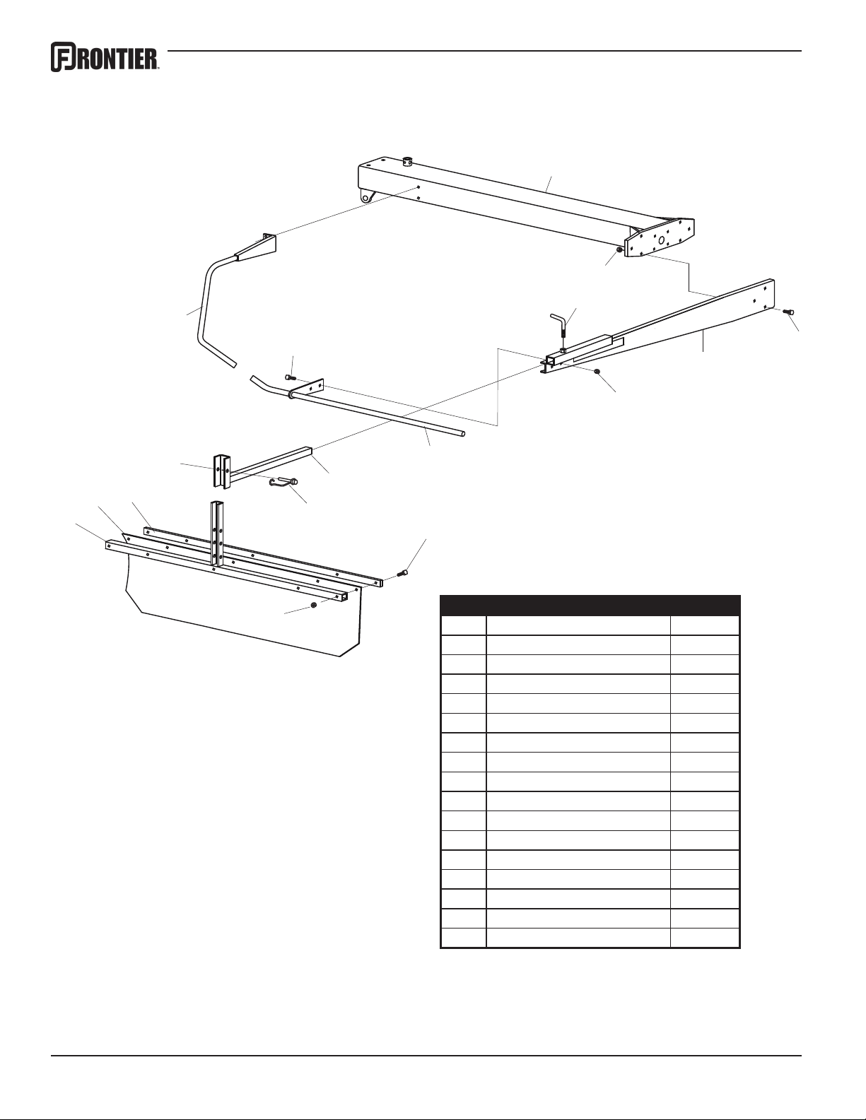
Tongue & Main Frame
4
39
2
1
3
5
40
38
37
6
7
8
9
10
12
11
13
14
26
27
28
41
29
25
24
30
23
22
31
21
20
18
19
17
15
16
32
36
31
33
32
34
35
Ref# Description Part#
Ref# Description Part# 21 Locknut, 5/16 5PQ002999
1 Complete PTO Shaft 5PQ503039 22 1.25-14 Machinery Bushing 5PQ500185
2 Ball Valve 5PQ502322 23 Roll Pin, 1/4 x 2 5PQ500017
3 Hydraulic Hose 5PQ502294 24 Front Cylinder 5PQ502279
4 Hose Support 5PQ502288 25 Front Cylinder Handle 5PQ503037
5 Bolt, 5/16 x 3/4 Truss Head 5PQ000210 26 Tongue Assembly 5PQ502237
6 Bolt, 5/16 x 1 5PQ000221 27 Locknut, 3/8 5PQ003000
7 Hose Support Washer 5PQ502308 28 PTO Stand 5PQ500015
8 PTO Guard 5PQ502234 29 Bolt, 3/8 x 1-1/4 5PQ000275
9 1-3/8 Flange Bearing 5PQ500067 30 Cylinder Mount 5PQ502218
10 Hydraulic Hose 5PQ502281 31 Roll Pin, 1/4 x 2 5PQ500017
11 Jack Mount Bracket 5PQ500005 32 1.25-14 Machinery Bushing 5PQ500185
12 Locknut, 3/8 5PQ003000 33 Tongue Pin 5PQ502225
13 Tunnel Assembly 5PQ502204 34 Pin & Chain 5PQ500012
14 Elbow Fitting, 1502-4-4 5PQ502300 35 Complete Jack 5PQ500009
15 Gearbox Complete 5PQ502264 36 Jack Handle 5PQ500010
16 Splined Yoke 5PQ500269 37 Drive Shaft 5PQ502257
17 Cross & Bearing Kit 5PQ500272 38 Bolt, 1/2 x 1-1/2 5PQ000435
18 Keyed Yoke 5PQ500270 39 Safety Chain 5PQ101200
19 Complete U-Joint 5PQ500268 40 Male Hydraulic Coupler 5PQ290105
20 Nut, 1/2 5PQ000940 41 Handle 5PQ502149
21
Page 24
16
15
Guards
1
5
6
2
3a Left Side
3b Right Side
4
7
12
13
14
11
8
9
10
Ref# Description Part#
1 Tunnel Assembly 5PQ502204
2 Bolt, 1/2 x 1/1-4 5PQ000420
3a Guard Arm, Left 5PQ502246
3b Guard Arm, Right 5PQ502239
4 Nut, 3/8 5PQ000915
5 Nut, 1/2 5PQ000940
6 Curtain Set Bolt 5PQ500148
7 Tine Guard Assembly, Rear 5PQ503096
8 Telescoping Tube 5PQ500149
9 Snapper Pin 5PQ500158
10 Bolt, 1/4 x 1-3/4 5PQ000187
11 Locknut, 1/4 5PQ003001
12 Curtain Mount Assembly 5PQ502251
13 Hay Curtain 5PQ502252
14 Curtain Bar 5PQ502247
15 Bolt 3/8 x 1 5PQ000270
16 Tine Guard Assembly, Front 5PQ503095
22
Page 25

Gearbox & Tine Arm
7
1
2
4
3
6
5
5
8
11
10
9
12
13
18
17
16
14
Ref# Description Part#
1 Hydraulic Hose 5PQ502281
2 Elbow Fitting, 1502-4-4 5PQ502300
3 Complete Gearbox, 9 Arm 5PQ502264
4 M10 x 80 Socket Head Bolt 5PQ001080
5 Radius Washer 5PQ701008
6 Tine Arm 5PQ903147
7 Bolt, 1/2 x 3-1/4 5PQ000478
8 Curved Rake Tine 5PQ500218
9 Locknut, 1/2 5PQ000950
10 Heavy Duty Flat Washer 5PQ000520
11 M10 Nylon Locknut 5PQ002822
12 Hexagon Shaft 5PQ500258
13 Gearbox Stand Assembly 5PQ502241
14 Rear Height Adjustment Lever 5PQ502274
15 Stainless Steel Handle 5PQ502149
16 3/4 x 3/4 Socket Head Bolt 5PQ000693
17 External Tooth Lock Washer 5PQ001087
18 Pipe Plug 5PQ502298
15
23
Page 26

Axle Assembly
15
16
18
17
14
13
12
10
11
8
9
21
7
5
4
2
1
3
32
32
31
33
34
35
30
31
6
26
27
28
29
25
23
22
24
19
23
20
22
36
37
Ref# Description Part# Ref# Description Part#
1 215/60-8 Tire, “C” Ply 5PQ500221 20 Stainless Steel Handle 5PQ502149
2 4-Hole Rim 5PQ500222 21 Elbow Fitting, 1501L-4-4 5PQ502301
3 Cotter Pin 5PQ500208 22 Roll Pin, 1/4 x 2 5PQ500017
4 Complete Hub 5PQ500199 23 1.25-14 Machinery Bushing 5PQ500185
5 Walking Beam Assembly 5PQ502240 24 Axle Assembly 5PQ502243
6 1.50-14 Machinery Bushing 5PQ500197 25 Gear Box Stand/Axle Pin 5PQ502244
7 Roll Pin, 1/4 x 2 5PQ500017 26 Axle/Cylinder Pin 5PQ502212
8 Rear Cylinder 5PQ502278 27 1.00-14 Machinery Bushing 5PQ001008
9 Roll Pin, 1/4 x 2 5PQ500017 28 Roll Pin, 1/4 x 2 5PQ500017
10 1.00-14 Machinery Bushing 5PQ001008 29 Plastic End Cap 5PQ502276
11 Head/Cylinder Pin 5PQ502213 30 Grease Seal 5PQ500201
12 1.00-14 Machinery Bushing 5PQ001008 31 Bearing, LM44643 5PQ500202
13 Roll Pin, 1/4 x 2 5PQ500017 32 Race, LM44610 5PQ500204
14 Hydraulic Hose 5PQ500116 33 Spindle Washer 5PQ500206
15 Hexagon Shaft 5PQ500258 34 Spindle Nut 5PQ500207
16 External Tooth Lock Washer 5PQ001087 35 Dust Cap 5PQ500209
17 3/4 x 3/4 Socket Head Bolt 5PQ000693 36 Lug Bolt, 1/2 x 20 5PQ500210
18 Gearbox Stand Assembly 5PQ502241 37 Rim & Tire Assembly 5PQ500220
19 Rear Height Adjustment Handle 5PQ502274
24
Page 27

Ref# Description Part#
1 Retaining Ring, Internal 5PQ500227
2 Washer 5PQ500228
3 Retaining Ring, External 5PQ500229
4 Bearing 5PQ500230
5 Spacer 5PQ500231
6 Pinion Gear 5PQ500232
7 Grease Fitting 5PQ500233
8 Lock Washer, 9/16 5PQ500234
9 Nut, 9/16 5PQ500235
10 Hexagon Shaft 5PQ500258
11 Bolt, M14 x 110 5PQ500236
12 Lock Washer, M14 5PQ500237
13 Bolt, 9/16 x 3-1/2 5PQ500238
14 Elbow Fitting /w Swivel 5PQ502300
15 Nipple 5PQ502299
16 Hexagon Shaft Cover 5PQ500240
17 Gear Box Cover 5PQ502333
18 Ring Gear 5PQ500242
19 Upper Bearing 5PQ500243
20 Cam Center 5PQ502334
21 Oil Seal 5PQ500245
22 Lower Bearing 5PQ500246
23 Oil Plug 5PQ500247
24 Gear Box Housing 5PQ502335
25 Retaining Ring 5PQ500249
26 Washer 5PQ500250
27 Cam Roller 5PQ500251
28 Crank Arm Shaft 5PQ502336
29 Gasket 5PQ500253
30 Spacer 5PQ502337
31 Cast Arm Support 5PQ500255
32 Bolt, M12 x 30 5PQ500256
33 Oil Seal 5PQ500257
34 Bushing 5PQ500279
35 Socket Head Bolt, M10 x 25 5PQ002426
36 Locknut, M14 5PQ002826
37 Bolt, M14 x 55 5PQ002658
38 NordLock Washer 5PQ000770
39 Oil Plug 5PQ502332
Complete Gear Box 5PQ502264
Rotary Gearbox
4
33
34
6
37
38
27
28
31
32
4
3
2
1
5
10
9
8
7
16
36
35
25
26
29
30
11
15
21
22
12
13
14
17
18
19
20
23
24
39
23
25
Page 28

7
5
4
SHAFT
CLUTCH
17
18
PTO Shaft
1
15
14
13
12
11
10
9
8
7
4
3
2
19
30
20
31
6
5
FRONT 39
24
35
!
!
DANGER
DANGER
25 (6x)
36
19
16
27
21
REAR 40
33
25
34
23
22
16
28
27
26
25
38
22
37
!
DANGER
1
41
29
32
Ref# Description Part # Ref# Description Part #
1 Radial Pin Clutch Assembly 5PQ500028 22 Spring Pin 5PQ500031
2 Retainer Ring 5PQ500048 23 Inner Prole 5PQ500032
3 Flanged Collar 5PQ500047 24 CV Cone & Bearing Assembly 5PQ500055
4 Lock Collar 5PQ500046 25 Screw 5PQ500058
5 Ball 5PQ500044 26 Shield Cone, 3 Rib 5PQ500056
6 Compression Spring 5PQ500045 27 Bearing Ring 5PQ500052
7 Flange Kit 5PQ500050 28 Outer Shield Tube 5PQ500053
8 Retainer Ring 5PQ500043 29 Decal 5PQ500059
9 Thrust Ring 5PQ500042 30 Support Bearing 5PQ500063
10 Seal Ring 5PQ500041 31 Inner Shield Tube 5PQ500054
11 Hub 5PQ500037 32 Safety Chain 5PQ500060
12 Cam 5PQ500038 33 Shield Cone, 4 Rib 5PQ500057
13 Outer Spring 5PQ500039 34 Grease Fitting 5PQ500062
14 Inner Spring 5PQ500040 35 Outer Prole & Sleeve 5PQ500033
15 Clutch Housing 5PQ500036 36 Decal 5PQ500061
16 Grease Fitting 5PQ500049 37 Inboard Yoke 5PQ500029
17 Yoke 5PQ500026 38 Cross & Bearing Kit 5PQ500051
18 Collar Kit 5PQ500064 39 Front Shaft Assembly 5PQ500024
19 Cross & Bearing Kit 5PQ500030 40 Rear Shaft Assembly 5PQ500907
20 Double Yoke 5PQ500027 41 Complete PTO Shaft 5PQ503039
21 Inboard Yoke 5PQ500034
26
Page 29
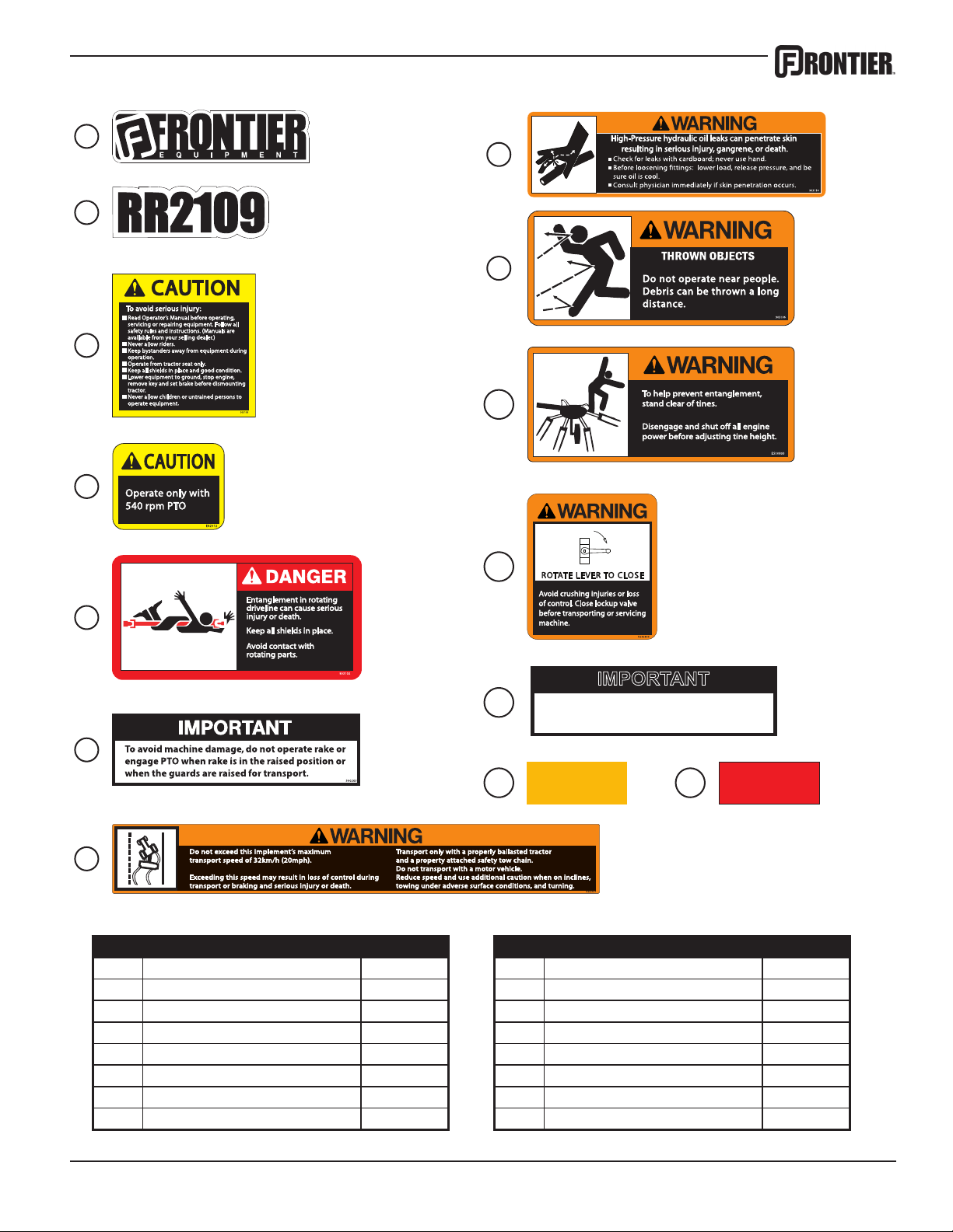
Decals & Reectors
Optimum raking speed is 400-450 PTO RPM.
IMPORTANT
1
8
2
9
3
10
4
11
5
12
6
13 14
7
Ref# Description Part# Ref# Description Part#
1 Frontier Logo 5PQ903110 9 Warning, Thrown Objects 5PQ903106
2 Model Number Decal, RR2109 5PQ903120 10 Warning, Prevent Entanglement 5PQ903123
3 Caution, General Information 5PQ903103 11 Warning, Lock-up Valve 5PQ903125
4 Caution, 540 RPM 5PQ903107 12 Important, Rake Speed 5PQ903116
5 Danger, PTO Entanglement 5PQ903122 13 Decal, Amber Retroreective 5PQ903121
6 Important, Avoid Damage 5PQ903126 14 Decal, Red Retroreective 5PQ903112
7 Warning, Do Not Exceed 5PQ903124 Complete Decal Kit 5PQ903128
8 Warning, Hydraulic Pressure 5PQ903114 French Decal/OM Conversion Kit 5PQ903180
27
Page 30

28
Page 31

Page 32

 Loading...