


 Loading...
John Deere 655, 755, 855, 955, 756 Technical Manual
...655, 755, 855, 955, 756 and 856 Compact Utility Tractors
TECHNICAL
MANUAL
John Deere
Lawn & Grounds Care Division
TM1360 (June 1996)
Litho in U.S.A

Introduction
FOREWORD
This manual is written for an experienced technician. Essential tools required in performing certain service work are identified in this manual and are recommended for use.
LIVE WITH SAFETY: Read the safety messages in the introduction of this manual and the cautions presented throughout the text of the manual.
PThis is the safety-alert symbol. When you see this symbol on the machine or in this manual, be alert to the potential for personal injury.
Technical manuals are divided in two parts: repair and diagnostics. Repair sections tell how to repair the components. Diagnostic sections help you identify the majority of routine failures quickly.
Information is organized in groups for the various components requiring service instruction. At the beginning of each group are summary listings of all applicable essential tools, service equipment and tools, other materials needed to do the job, service parts kits, specifications, wear tolerances, and torque values.
Binders, binder labels, and tab sets can be ordered by John Deere dealers direct from the John Deere Distribution Service Center.
This manual is part of a total product support program.
FOS MANUALSÐREFERENCE
TECHNICAL MANUALSÐMACHINE SERVICE
COMPONENT MANUALSÐCOMPONENT SERVICE
Fundamentals of Service (FOS) Manuals cover basic theory of operation, fundamentals of troubleshooting, general maintenance, and basic type of failures and their causes. FOS Manuals are for training new personnel and for reference by experienced technicians.
Technical Manuals are concise guides for specific machines. Technical manuals are on-the-job guides containing only the vital information needed for diagnosis, analysis, testing, and repair.
Component Technical Manuals are concise service guides for specific components. Component technical manuals are written as stand-alone manuals covering multiple machine applications.
NOTE: The 756 and 856 tractors are identical to the 755 and 855 tractors; therefore, all information pertaining to the 755 also pertains to the 756 and the same is true for the 855 and the 856 tractors. The 655, 756 and 856 tractors were all discontinued before the late model 755 and 855 tractors and the new 955 tractors were produced. Therefore, any late model references do not include the 655, 756, and 856 tractors.
|
MX,TM1360,IFC -19-16OCT91 |
TM1360 (16OCT91) |
55, 56 Series Tractors |
010395

Contents
SECTION 10—GENERAL INFORMATION
Group 05—Safety
Group 10—Repair Specifications Group 15—Repair Information
Group 20—Fuels, Lubricants, and Coolants Group 25—Serial Number Locations
SECTION 20—DIESEL ENGINE REPAIR
Group 05—Yanmar Diesel Engine Repair Group 10—Remove and Install Oil Cooler Group 15—Remove and Install Radiator Group 20—Remove and Install Diesel Engine
SECTION 30—FUEL AND AIR REPAIR
Group 05—Fuel Transfer Pump Group 10—Fuel Tank
Group 15—Fuel Tank Tube and Sender Group 20—Air Cleaner
SECTION 40—ALTERNATOR REPAIR
Group 05—Alternator Repair Specifications Group 10—Alternator Installation
SECTION 50—POWER TRAIN REPAIR
Group 05—Hydrostatic Transmission Group 10—Transaxle
Group 15—Final Drives
Group 20—Mechanical Front Wheel Drive (MFWD)
Group 25—Power Train Gears and Shafts Group 30—Speed Control Linkage
SECTION 60—STEERING AND BRAKES REPAIR
Group 05—Standard Front Axle Group 10—Steering Valve Group 15—Brake Linkage
SECTION 70—HYDRAULICS REPAIR
Group 05—Hydraulic Pump
Group 10—Flow Divider and Selective Control Valves (SCV’s)
Group 15—Rockshaft Group 20—Hydraulic Hoses
SECTION 80—MISCELLANEOUS REPAIR
Group 15—Operator’s Seat Group 20—European Roll-Gard ® Group 25—German Rear Hitch Group 30—3-Point Hitch
SECTION 210—MACHINE OPERATIONAL CHECKOUT PROCEDURE
Group 05—Machine Operational Checkout Procedure
SECTION 220—ENGINE/FUEL OPERATION AND TESTS
Group 05—Engine Systems Operational Checkout Procedure
Group 10—Engine System Diagnosis
SECTION 240—ELECTRICAL OPERATION AND TESTS
Group 05—Electrical System Checkout Group 10—Electrical System Diagnosis Group 15—Theory of Operation
SECTION 250—POWER TRAIN OPERATION
AND TESTS
Group 05—Power Train System Checkout Group 10—Power Train Tests and Adjustments Group 15—Theory of Operation
SECTION 260—STEERING AND BRAKE OPERATION AND TESTS
Group 05—Steering and Brakes System Checkout Group 10—Steering and Brakes Tests and
Adjustments Group 15—Theory of Operation
SECTION 270—HYDRAULIC OPERATION AND TESTS
Group 05—Hydraulic System Checkout Group 10—Hydraulic System Tests and
Adjustments Group 15—Theory of Operation
INDEX
All information, illustrations and specifications in this manual are based on the latest information available at the time of publication. The right is reserved to make changes at any time without notice.
TM 1360-19-01Jun 96
COPYRIGHT©1996
DEERE & COMPANY
Moline, Illinois
All rights reserved
A John Deere ILLUSTRUCTION Manual
Previous Editions
Copyright© 1991, 1990, 1986 Deere & Company
10
20
30
40
50
60
70
80
210
220
i

Contents
240
250
260
270
INDX
ii

10
Section 10
General Information
Contents
|
Page |
|
Page |
Group 05—Safety |
|
Group 25—Serial Number Locations |
|
Safety Items . . . . . . . . . . . . . . . . . . . . . . . . . |
10-05-1 |
Product Serial Number . . . . . . . . . . . . . . . . |
10-25-1 |
Group 10—Repair Specifications |
|
Engine Serial Number. . . . . . . . . . . . . . . . . |
10-25-1 |
|
Transaxle Serial Number . . . . . . . . . . . . . . |
10-25-1 |
|
General Tractor Specifications . . . . . . . . . . . |
10-10-1 |
Mower Deck Serial Number . . . . . . . . . . . . |
10-25-1 |
Group 15—Repair Information |
|
|
|
Metric Fastener Torque Values. . . . . . . . . . . |
10-15-1 |
|
|
Inch Fastener Torque Values . . . . . . . . . . . . |
10-15-2 |
|
|
O-Ring Face Seal Fittings . . . . . . . . . . . . . . |
10-15-3 |
|
|
O-Ring Boss Fittings . . . . . . . . . . . . . . . . . . |
10-15-4 |
|
|
Group 20—Fuels, Lubricants, and Coolants
Diesel Fuel—North America. . . . . . . . . . . . .10-20-1
Diesel Fuel Lubricity—North America . . . . .10-20-1
Diesel Fuel Storage—North America . . . . . .10-20-1
Diesel Fuel—Europe . . . . . . . . . . . . . . . . . .10-20-2
Diesel Fuel Lubricity—Europe . . . . . . . . . . .10-20-2
Diesel Fuel Storage—Europe . . . . . . . . . . .10-20-2
Engine Oil—North America . . . . . . . . . . . . .10-20-3
Engine Oil—Europe . . . . . . . . . . . . . . . . . . .10-20-4
Break-in Engine Oil—North America . . . . . .10-20-5
Break-in Engine Oil—Europe . . . . . . . . . . . .10-20-6
Hydrostatic Transmission and
Hydraulic Oil— North America. . . . . . . . . .10-20-7
Hydrostatic Transmission and
Hydraulic Oil— Europe . . . . . . . . . . . . . . .10-20-8
Gear Case Oil (MFWD)—North America . . .10-20-9
Gear Case Oil (MFWD)—Europe. . . . . . . .10-20-10
Grease—North America. . . . . . . . . . . . . . . 10-20-11
Grease—Europe . . . . . . . . . . . . . . . . . . . .10-20-12
North America
Alternative Lubricants. . . . . . . . . . . . . . . . .10-20-13
Synthetic Lubricants. . . . . . . . . . . . . . . . . .10-20-13
Lubricant Storage. . . . . . . . . . . . . . . . . . . .10-20-13
Mixing of Lubricants . . . . . . . . . . . . . . . . . .10-20-13
Oil Filters . . . . . . . . . . . . . . . . . . . . . . . . . .10-20-13
Europe
Alternative Lubricants. . . . . . . . . . . . . . . . .10-20-14
Synthetic Lubricants. . . . . . . . . . . . . . . . . .10-20-14
Lubricant Storage. . . . . . . . . . . . . . . . . . . .10-20-14
Mixing of Lubricants . . . . . . . . . . . . . . . . . .10-20-14
Oil Filters . . . . . . . . . . . . . . . . . . . . . . . . . .10-20-14
Diesel Engine Coolant—North America . . .10-20-15
Diesel Engine Coolant—Europe . . . . . . . .10-20-16
10-1

Contents
10
TM1360 (16OCT91) |
10-2 |
55, 56 Series Tractors |
010395

HANDLE FLUIDS SAFELYÐAVOID FIRES
When you work around fuel, do not smoke or work near heaters or other fire hazards.
Store flammable fluids away from fire hazards. Do not incinerate or puncture pressurized containers.
Make sure machine is clean of trash, grease, and debris.
Do not store oily rags; they can ignite and burn spontaneously.
PREVENT BATTERY EXPLOSIONS
Keep sparks, lighted matches, and open flame away from the top of battery. Battery gas can explode.
Never check battery charge by placing a metal object across the posts. Use a volt-meter or hydrometer.
Do not charge a frozen battery; it may explode. Warm battery to 16ÊC (60ÊF).
PREPARE FOR EMERGENCIES
Be prepared if a fire starts.
Keep a first aid kit and fire extinguisher handy.
Keep emergency numbers for doctors, ambulance service, hospital, and fire department near your telephone.
TM1360 (16OCT91) |
10-05-1 |
Group 05
Safety
10
05
1
<![if ! IE]><![endif]>TS227 -UN-23AUG88
DX,FLAME -19-04JUN90
<![if ! IE]><![endif]>TS204 -UN-23AUG88
DX,SPARKS -19-04JUN90
<![if ! IE]><![endif]>TS291 -UN-23AUG88
DX,FIRE2 -19-04JUN90
55, 56 Series Tractors
010395

Safety
PREVENT ACID BURNS
10
05 Sulfuric acid in battery electrolyte is poisonous. It is 2 strong enough to burn skin, eat holes in clothing, and
cause blindness if splashed into eyes.
Avoid the hazard by:
1. Filling batteries in a well-ventilated area.
2. Wearing eye protection and rubber gloves.
3. Avoiding breathing fumes when electrolyte is added.
4. Avoiding spilling or dripping electrolyte.
5. Use proper jump start procedure.
If you spill acid on yourself:
1.Flush your skin with water.
2.Apply baking soda or lime to help neutralize the acid.
3.Flush your eyes with water for 10Ð15 minutes. Get medical attention immediately.
If acid is swallowed:
1.Drink large amounts of water or milk.
2.Then drink milk of magnesia, beaten eggs, or vegetable oil.
3.Get medical attention immediately.
<![endif]> TS203 -UN-23AUG88
DX,POISON -19-04JUN90
TM1360 (16OCT91) |
10-05-2 |
55, 56 Series Tractors |
010395
Safety
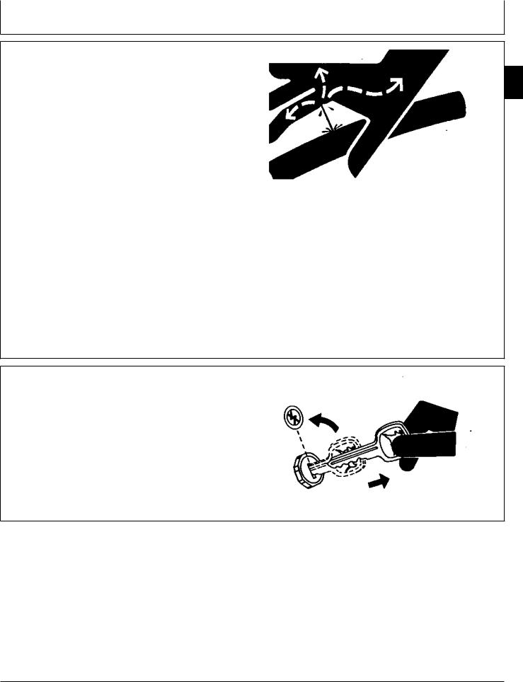
AVOID HIGH-PRESSURE FLUIDS
Escaping fluid under pressure can penetrate the skin causing serious injury.
Avoid the hazard by relieving pressure before disconnecting hydraulic or other lines. Tighten all connections before applying pressure.
Search for leaks with a piece of cardboard. Protect hands and body from high pressure fluids.
If an accident occurs, see a doctor immediately. Any fluid injected into the skin must be surgically removed within a few hours or gangrene may result. Doctors unfamiliar with this type of injury should reference a knowledgeable medical source. Such information is available from Deere & Company Medical Department in Moline, Illinois, U.S.A.
PARK MACHINE SAFELY
Before working on the machine:
·Lower all equipment to the ground.
·Stop the engine and remove the key.
·Disconnect the battery ground strap.
·Hang a ªDO NOT OPERATEº tag in operator station.
TM1360 (16OCT91) |
10-05-3 |
10
05
3
<![if ! IE]><![endif]>X9811 -UN-23AUG88
DX,FLUID -19-09AUG91
<![if ! IE]><![endif]>TS230 -UN-24MAY89
DX,PARK -19-04JUN90
55, 56 Series Tractors
010395

Safety
SUPPORT MACHINE PROPERLY
10
05 Always lower the attachment or implement to the ground 4 before you work on the machine. If you must work on a
lifted machine or attachment, securely support the machine or attachment.
Do not support the machine on cinder blocks, hollow tiles, or props that may crumble under continuous load. Do not work under a machine that is supported solely by a jack. Follow recommended procedures in this manual.
WEAR PROTECTIVE CLOTHING
Wear close fitting clothing and safety equipment appropriate to the job.
Prolonged exposure to loud noise can cause impairment or loss of hearing.
Wear a suitable hearing protective device such as earmuffs or earplugs to protect against objectionable or uncomfortable loud noises.
Operating equipment safely requires the full attention of the operator. Do not wear radio or music headphones while operating machine.
SERVICE MACHINES SAFELY
Tie long hair behind your head. Do not wear a necktie, scarf, loose clothing, or necklace when you work near machine tools or moving parts. If these items were to get caught, severe injury could result.
Remove rings and other jewelry to prevent electrical shorts and entanglement in moving parts.
TM1360 (16OCT91) |
10-05-4 |
<![endif]>TS229 -UN-23AUG88
DX,LOWER -19-04JUN90
<![if ! IE]><![endif]>TS206 -UN-23AUG88
DX,WEAR -19-10SEP90
<![if ! IE]><![endif]>TS228 -UN-23AUG88
DX,LOOSE -19-04JUN90
55, 56 Series Tractors
010395

Safety
WORK IN VENTILATED AREA
Engine exhaust fumes can cause sickness or death. If it is necessary to run an engine in an enclosed area, remove the exhaust fumes from the area with an exhaust pipe extension.
If you do not have an exhaust pipe extension, open the doors and get outside air into the area.
ILLUMINATE WORK AREA SAFELY
Illuminate your work area adequately but safely. Use a portable safety light for working inside or under the machine. Make sure the bulb is enclosed by a wire cage. The hot filament of an accidentally broken bulb can ignite spilled fuel or oil.
REPLACE SAFETY SIGNS
Replace missing or damaged safety signs. See the machine operator's manual for correct safety sign placement.
USE PROPER LIFTING EQUIPMENT
Lifting heavy components incorrectly can cause severe injury or machine damage.
Follow recommended procedure for removal and installation of components in the manual.
TM1360 (16OCT91) |
10-05-5 |
10
05
5
<![if ! IE]><![endif]>TS220 -UN-23AUG88
DX,AIR -19-04JUN90
<![if ! IE]><![endif]>TS223 -UN-23AUG88
DX,LIGHT -19-04JUN90
<![if ! IE]><![endif]>TS201 -UN-23AUG88
DX,SIGNS1 -19-04JUN90
<![if ! IE]><![endif]>TS226 -UN-23AUG88
DX,LIFT -19-04JUN90
55, 56 Series Tractors
010395

Safety
KEEP ROPS INSTALLED PROPERLY
10
05 Make certain all parts are reinstalled correctly if the 6 roll-over protective structure (ROPS) is loosened or removed for any reason. Tighten mounting bolts to
proper torque.
The protection offered by ROPS will be impaired if ROPS is subjected to structural damage, is involved in an overturn incident, or is in any way altered by welding, bending, drilling, or cutting. A damaged ROPS should be replaced, not reused.
SERVICE TIRES SAFELY
Explosive separation of a tire and rim parts can cause serious injury or death.
Do not attempt to mount a tire unless you have the proper equipment and experience to perform the job.
Always maintain the correct tire pressure. Do not inflate the tires above the recommended pressure. Never weld or heat a wheel and tire assembly. The heat can cause an increase in air pressure resulting in a tire explosion. Welding can structurally weaken or deform the wheel.
When inflating tires, use a clip-on chuck and extension hose long enough to allow you to stand to one side and NOT in front of or over the tire assembly. Use a safety cage if available.
Check wheels for low pressure, cuts, bubbles, damaged rims or missing lug bolts and nuts.
TM1360 (16OCT91) |
10-05-6 |
<![endif]>TS212 -UN-23AUG88
DX,ROPS3 -19-04JUN90
<![if ! IE]><![endif]>TS211 -UN-23AUG88
DX,RIM -19-24AUG90
55, 56 Series Tractors
010395

Safety
AVOID HARMFUL ASBESTOS DUST
Avoid breathing dust that may be generated when handling components containing asbestos fibers. Inhaled asbestos fibers may cause lung cancer.
Components in products that may contain asbestos fibers are brake pads, brake band and lining assemblies, clutch plates, and some gaskets. The asbestos used in these components is usually found in a resin or sealed in some way. Normal handling is not hazardous as long as airborne dust containing asbestos is not generated.
Avoid creating dust. Never use compressed air for cleaning. Avoid brushing or grinding material containing asbestos. When servicing, wear an approved respirator. A special vacuum cleaner is recommended to clean asbestos. If not available, apply a mist of oil or water on the material containing asbestos.
Keep bystanders away from the area.
WORK IN CLEAN AREA
Before starting a job:
·Clean work area and machine.
·Make sure you have all necessary tools to do your job.
·Have the right parts on hand.
·Read all instructions thoroughly; do not attempt shortcuts.
TM1360 (16OCT91) |
10-05-7 |
10
05
7
<![if ! IE]><![endif]>TS220 -UN-23AUG88
DX,DUST -19-15MAR91
<![if ! IE]><![endif]>T6642EJ -UN-18OCT88
DX,CLEAN -19-04JUN90
55, 56 Series Tractors
010395

Safety
USE PROPER TOOLS
10
05 Use tools appropriate to the work. Makeshift tools and 8 procedures can create safety hazards.
Use power tools only to loosen threaded parts and fasteners.
For loosening and tightening hardware, use the correct size tools. DO NOT use U.S. measurement tools on metric fasteners. Avoid bodily injury caused by slipping wrenches.
Use only service parts meeting John Deere specifications.
DISPOSE OF WASTE PROPERLY
Improperly disposing of waste can threaten the environment and ecology. Potentially harmful waste used with John Deere equipment include such items as oil, fuel, coolant, brake fluid, filters, and batteries.
Use leakproof containers when draining fluids. Do not use food or beverage containers that may mislead someone into drinking from them.
Do not pour waste onto the ground, down a drain, or into any water source.
Air conditioning refrigerants escaping into the air can damage the Earth's atmosphere. Government regulations may require a certified air conditioning service center to recover and recycle used air conditioning refrigerants.
Inquire on the proper way to recycle or dispose of waste from your local environmental or recycling center, or from your John Deere dealer.
TM1360 (16OCT91) |
10-05-8 |
<![endif]>TS779 -UN-08NOV89
DX,REPAIR -19-04JUN90
<![if ! IE]><![endif]>TS1133 -UN-26NOV90
DX,DRAIN -19-09AUG91
55, 56 Series Tractors
010395

Safety
LIVE WITH SAFETY
Before returning machine to customer, make sure machine is functioning properly, especially the safety systems. Install all guards and shields.
10
05
9
<![if ! IE]><![endif]>TS231 -19-07OCT88
DX,LIVE -19-04JUN90
TM1360 (16OCT91) |
10-05-9 |
55, 56 Series Tractors |
010395

Safety
10
05
10
TM1360 (16OCT91) |
10-05-10 |
55, 56 Series Tractors |
010395

Group 10
Repair Specifications
GENERAL TRACTOR SPECIFICATIONS
ITEM |
655 |
755/756 |
855/856 |
955 |
ENGINE: |
|
|
|
|
Engine Model . . . . . . . . |
. . . . 3TN66UJ |
3TNA72UJ |
3TN75RJ |
3TN84RJ |
Engine Horsepower, Net |
. . . 16 (11.9 kW) |
20 (14.9 kW) |
24 (17.9 kW) |
33 (24.6 kW) |
PTO Horsepower . . . . . . |
. 10.6 (8.1 kW) |
15 (11.2 kW) |
19 (14.2 kW) |
27 (20.1 kW) |
Rated Engine Speed. . . . |
. . . 3200 rpm |
3200 rpm |
3200 rpm |
3200 rpm |
Type . . . . . . . . . . . . . . . . |
. . . . Diesel |
Diesel |
Diesel |
Diesel |
Operating Range . . . . . . |
. 1400-3425 rpm |
1400-3425 rpm |
1400-3425 rpm |
1400-3425 rpm |
Number of Cylinders . . . . |
. . . . . . 3 |
3 |
3 |
3 |
Displacement . . . . . . . . . |
. . 40.2 cu. in. |
53.6 cu. in. |
60.7 cu. in. |
87.3 cu. in. |
|
658 cm³ |
879 cm³ |
995 cm³ |
1430 cm³ |
Bore and Stroke . . . . . . . |
. . 2.59x2.53 in. |
2.83x2.83 in. |
2.95x2.95 in. |
3.31x3.39 in. |
|
(66x64.2 mm) |
(72x72 mm) |
(75x75 mm) |
(84x86 mm) |
Compression Ratio . . . . . |
. . . . 22.4:1 |
22.3:1 |
17.8:1 |
18.0:1 |
Lubrication . . . . . . . . . . . |
. . . Pressured |
Pressured |
Pressured |
Pressured |
Cooling System. . . . . . . . |
. . Water-pump |
Water-pump |
Water-pump |
Water-pump |
Air Cleaner . . . . . . . . . . . |
. Dry-Type with |
Dry-Type with |
Dry-Type with |
Dry-Type with |
|
Safety Element |
Safety Element |
Safety Element |
Safety Element |
Engine Shutoff . . . . . . . . |
. . . . . Key |
Key |
Key |
Key |
Engine Torque at |
|
|
|
|
Rated Speed. . . . . . . . . |
. . . . 35 N•m |
45 N•m |
58 N•m |
73 N•m |
|
(26 lb-ft) |
(33 lb-ft) |
(39 lb-ft) |
(54 lb-ft) |
ELECTRICAL SYSTEM: |
|
|
|
|
Type . . . . . . . . . . . . . . . . |
. . . . 12 volt |
12 volt |
12 volt |
12 volt |
Battery Size . . . . . . . . . |
491 Cold Cranking |
491 Cold Cranking |
475 Cold Cranking |
475 Cold Cranking |
|
Amps @ -18° C |
Amps @ -18° C |
Amps @ -18° C |
Amps @ -18° C |
Alternator . . . . . . . . . . . . |
. . . . 35 Amp |
35 Amp |
35 Amp |
N/A |
|
40 Amp |
40 Amp |
40 Amp |
40 Amp |
Starter Size . . . . . . . . . . . |
. 1.3 hp (1.0 kW) |
1.3 hp (1.0 kW) |
1.3 hp (1.0 kW) |
1.9 hp (1.4 kW) |
FUEL SYSTEM: |
|
|
|
|
Type . . . . . . . . . . . . . . . . |
Indirect Injection |
Indirect Injection |
Direct Injection |
Direct Injection |
Injection Pump Type . . . . |
. . .In-line with |
In-line with |
In-line with |
In-line with |
|
Electric Shutoff |
Electric Shutoff |
Electric Shutoff |
Electric Shutoff |
Gallon/hr at 75% load |
|
|
|
|
(mowing) . . . . . . . . . . . . |
. .Not Available |
0.86 |
0.79 |
1.4 |
DRIVE TRAIN: |
|
|
|
|
Transmission Type . . . . |
Hydrostatic-2-range |
Hydrostatic-2-range |
Hydrostatic-2-range |
Hydrostatic-2-range |
Transaxle Speed |
|
|
|
|
Ranges . . . . . . . . . . . . . |
. . . . High/Lo |
High/Lo |
High/Lo |
High/Lo |
Number of Speeds . . . . . |
. . . . Infinite |
Infinite |
Infinite |
Infinite |
Final Drive. . . . . . . . . . . . |
. . . Planetary |
Planetary |
Planetary |
Planetary |
Brakes. . . . . . . . . . . . . . . |
. . . Wet Disk |
Wet Disk |
Wet Disk |
Wet Disk |
Steering . . . . . . . . . . . . . |
. . . . Power |
Power |
Power |
Power |
Drawbar Tonque Weight |
|
|
|
|
Capacity . . . . . . . . . . . . |
.675 lb. (306 kg) |
675 lb. (306 kg) |
675 lb. (306 kg) |
800 lb. (363 kg) |
10
10
1
10-10-1

Repair Specifications/General Specifications
10 |
GENERAL SPECIFICATIONS—CONTINUED |
|
|
||
10 |
|
|
|
|
|
2 |
ITEM |
655 |
755/756 |
855/856 |
955 |
|
HYDRAULIC SYSTEM: |
|
|
|
|
|
Type of System . . . . . . . . |
. Open Center |
Open Center |
Open Center |
Open Center |
|
Working Pressure . . . . . . |
. . . 2050 psi |
2050 psi |
2050 psi |
2500 psi |
|
|
(14135 kPa) |
(14135 kPa) |
(14135 kPa) |
(17240 kPa) |
|
Pump Type . . . . . . . . . . . |
. Gerotor Gear |
Gerotor Gear |
Gerotor Gear |
Gerotor Gear |
|
Pump Capacity . . . . . . . . |
. . . . 4 gpm |
5.6 gpm |
5.6 gpm |
7.2 gpm |
|
|
(0.25 L/s) |
(0.35 L/s) |
(0.35 L/s) |
(0.45 L/s) |
|
3-PT. Hitch Type . . . . . . . |
Cat. 1 (Standard) |
Cat. 1 (Standard) |
Cat. 1 |
Cat. 1 |
|
Hitch Lift Capacity |
|
|
|
|
|
(24 in. behind link arms) |
|
|
|
|
|
Early Models . . . . . . . . . |
. . . 785 lbs. |
785 lbs. |
785 lbs. |
957 lbs. |
|
|
(357 kg) |
(357 kg) |
(357 kg) |
(434 kg) |
|
Late Models or Retrofit . |
. . . . . N/A |
SN 180250— |
SN 180450— |
SN 180525— |
|
|
N/A |
1005 lbs. |
1005 lbs. |
1177 lbs. |
|
|
|
(456 kg) |
(456 kg) |
(534 kg) |
|
Lift Control Type . . . . . . |
. . . Position |
Position |
Position |
Position |
|
PTO: |
|
|
|
|
|
Type. . . . . . . . . . . . . . . . . |
Live Independent |
Live Independent |
Live Independent |
Live Independent |
|
Speed (PTO rpm at 3200 |
|
|
|
|
|
engine rpm—full load): |
|
|
|
|
|
Mid (1:1 gear ratio) . . . . |
. . . 2100 rpm |
2100 rpm |
2100 rpm |
2100 rpm |
|
Rear (1:3 gear ratio) . . . |
. . . 540 rpm |
540 rpm |
540 rpm |
540 rpm |
|
Clutch . . . . . . . . . . . . . . . |
. . . Hydraulic |
Hydraulic |
Hydraulic |
Hydraulic |
|
|
Multi-Disk |
Multi-Disk |
Multi-Disk |
Multi-Disk |
|
Brake . . . . . . . . . . . . . . . . |
. .Hydraulically |
Hydraulically |
Hydraulically |
Hydraulically |
|
|
Controlled |
Controlled |
Controlled |
Controlled |
|
MOWER BLADE TIP SPEED |
|
|
|
|
|
(at 3200 engine rpm full load): |
|
|
|
|
|
50 Inch Mower. . . . . . . . . |
. 15,371 ft/min |
N/A |
N/A |
N/A |
|
|
(4688 m/min) |
|
|
|
|
1:1.04 Gear Ratio . . . . . |
Spindle rpm 3389 |
N/A |
N/A |
N/A |
|
60 Inch Mower. . . . . . . . . |
. . . . . N/A |
15,471 ft/min |
15,471 ft/min |
15,471 ft/min |
|
|
|
(4719 m/min) |
(4719 m/min) |
(4719 m/min) |
|
1:1 Gear Ratio . . . . . . . . |
. . . . . N/A |
Spindle rpm 2883 |
Spindle rpm 2883 |
Spindle rpm 2883 |
|
72 Inch Mower. . . . . . . . . |
. . . . . N/A |
15,167 ft/min |
15,167 ft/min |
15,167 ft/min |
|
|
|
(4626 m/min) |
(4626 m/min) |
(4626 m/min) |
|
1:1 Gear Ratio . . . . . . . . |
. . . . . N/A |
Spindle rpm 2321 |
Spindle rpm 2321 |
Spindle rpm 2321 |
|
261 Inch Mower. . . . . . . . |
. . . . . N/A |
14,465 ft/min |
14,465 ft/min |
14,465 ft/min |
|
|
|
(4412 m/min) |
(4412 m/min) |
(4412 m/min) |
|
1:3 Gear Ratio . . . . . . . . |
. . . . . N/A |
Spindle rpm 2695 |
Spindle rpm 2695 |
Spindle rpm 2695 |
|
272 Inch Mower. . . . . . . . |
. . . . . N/A |
14,601 ft/min |
14,601 ft/min |
14,601ft/min |
|
|
|
(4453 m/min) |
(4453 m/min) |
(4453 m/min) |
|
1:3 Gear Ratio . . . . . . . . |
. . . . . N/A |
Spindle rpm 2234 |
Spindle rpm 2234 |
Spindle rpm 2234 |
|
|
|
|
|
|
10-10-2

Repair Specifications/General Specifications
GENERAL SPECIFICATIONS—CONTINUED |
|
|
10 |
|
||
|
|
10 |
|
|||
|
|
|
|
|
|
|
ITEM |
655 |
755/756 |
855/856 |
955 |
3 |
|
FLUID CAPACITIES: |
|
|
|
|
|
|
|
|
|
|
|
|
|
Fuel Tank . . . . . . . . . . . |
3.95 U.S. gal (15 L) |
4.4 U.S. gal (16.7 L) |
6.6 U.S. gal (25 L) |
6.6 U.S. gal (25 L) |
|
|
Cooling System. . . . . . . |
. 4 U.S. qt. (3.8 L) |
4 U.S. qt. (3.8 L) |
4.8 U.S. qt. (4.5 L) |
4.8 U.S. qt. (4.5 L) |
|
|
Crankcase (w/filter). . . . |
.2.5 U.S. qt. (2.4 L) |
2.86 U.S. qt. (2.7 L) |
4.1 U.S. qt. (3.9 L) |
4.4 U.S. qt. (4.2 L) |
|
|
Transmission and |
|
|
|
|
|
|
Hydraulic System . . . . |
4.5 U.S. gal. (17 L) |
4.5 U.S. gal. (17 L) |
4.5 U.S. gal. (17 L) |
4.5 U.S. gal. (17 L) |
|
|
MFWD Gear Case . . . . |
2.25 U.S. qt. (2.13 L) |
2.25 U.S. qt. (2.13 L) |
2.25 U.S. qt. (2.13 L) |
3.5 U.S. qt. (3.3 L) |
|
|
WEIGHT (includes fuel, oil, coolant and R-1 tires): |
|
|
|
|
||
2WD . . . . . . . . . . . . . . . |
. . . . 1584 lbs. |
1700 lbs. |
1790 lbs. |
N/A |
|
|
|
(718 kg) |
(771 kg) |
(812 kg) |
|
|
|
MFWD. . . . . . . . . . . . . . |
. . . . 1680 lbs. |
1835 lbs. |
1870 lbs. |
1990 lbs. |
|
|
|
(762 kg) |
(832 kg) |
(848 kg) |
(903 kg) |
|
|
SERVICE INTERVALS: |
|
|
|
|
|
|
Engine |
|
|
|
|
|
|
Valve Adjustment . . . . . |
. . . . 300 Hours |
300 Hours |
300 Hours |
300 Hours |
|
|
Primary Filter . . . . . . . . |
. . . . 400 Hours |
400 Hours |
400 Hours |
400 Hours |
|
|
|
|
or every two years |
|
|
|
|
Secondary Filter . . . . . . |
. Every two years |
Every two years |
Every two years |
Every two years |
|
|
|
or when every third primary filter is installed |
|
|
|
||
GROUND SPEEDS (at full engine rpm): |
|
|
|
|
|
|
Forward High Range. . . |
. . . 0—10.0 mph |
0—10.6 mph |
0—11.0 mph |
0—11.4 mph |
|
|
|
(0—16.1 K/hr) |
(0—17.1 K/hr) |
(0—17.7 K/hr) |
(0—18.3 K/hr) |
|
|
Forward Lo Range . . . . |
. . . 0—05.4 mph |
0—05.8 mph |
0—06.0 mph |
0—05.1 mph |
|
|
|
(0—08.7 K/hr) |
(0—09.3 K/hr) |
(0—09.7 K/hr) |
(0—08.2 K/hr) |
|
|
Reverse High And Lo . . |
. . . 0—05.0 mph |
0—05.3 mph |
0—05.5 mph |
0—05.7 mph |
|
|
|
(0—08.1 K/hr) |
(0—08.5 K/hr) |
(0—08.9 K/hr) |
(0—09.2 K/hr) |
|
|
ENGINE COOLANT HEATER: |
|
|
|
|
|
|
|
Current Draw |
Current Draw |
Current Draw |
Current Draw |
|
|
|
400 Watts |
400 Watts |
400 Watts |
400 Watts |
|
|
SPARK ARRESTER: |
|
|
|
|
|
|
|
Not Available |
Available |
Available |
Available |
|
|
|
|
|
|
|
|
|
10-10-3

Repair Specifications/General Specifications
10
10
4
TM1360 (16OCT91) |
10-10-4 |
55, 56 Series Tractors |
010395
METRIC FASTENER TORQUE VALUES
|
4.8 |
|
|
8.8 |
9.8 |
|
||||||||||||||||
Property |
|
|
|
|
|
|
|
|
|
|
|
|
|
|
|
|
|
|
|
|
|
|
Class |
|
|
|
|
|
|
|
|
|
|
|
|
|
|
|
|
|
|
|
|
|
|
|
|
|
|
|
|
|
|
|
|
|
|
|
|
|
|
|
|
|
|
|
|
|
and |
|
|
|
|
|
4.8 |
|
8.8 |
9.8 |
|
||||||||||||
|
|
|
|
|
|
|
||||||||||||||||
Head |
|
|
|
|
|
|
|
|
|
|
|
|
|
|
|
|
|
|
|
|
|
|
Markings |
|
|
|
|
|
|
|
|
|
|
|
|
4.8 |
|
|
8.8 |
|
|
|
|
9.8 |
|
|
|
|
|
|
|
|
|
|
|
|
|
|
|
|
|
|
|
|
||||
|
|
|
|
|
|
|
|
|
|
|
|
|
|
|
|
|
|
|
|
|
|
|
Property |
5 |
|
|
|
|
|
10 |
|
|
|
||||||||||||
|
|
|
|
|
|
|
|
|
|
|
|
|
|
|
|
|
|
|
|
|
|
|
Class |
|
|
|
|
|
|
|
|
|
|
|
|
|
|
|
|
|
|
|
|
|
|
and |
<![if ! IE]> <![endif]>5 |
|
|
|
|
|
<![if ! IE]> <![endif]>10 |
|
|
|
||||||||||||
Nut |
|
|
|
|
|
|
|
|
||||||||||||||
5 |
|
|
|
|
|
|
|
|
|
|
|
10 |
|
|
|
|
|
|
||||
|
|
|
|
|
|
|
|
|
|
|
|
|
|
|
|
|
||||||
Markings |
|
|
|
|
|
|
|
|
|
|
|
|
|
|
|
|
|
|||||
|
|
|
|
|
|
|
|
|
|
|
|
|
|
|
|
|
|
|
|
|
|
|
|
|
|
|
|
|
|
|
|
|
|
|
|
|
|
|
|
|
|
|
|
|
|
Group 15
Repair Information
10.9 |
|
|
12.9 |
|
|
|||||
10.9 |
|
12.9 |
|
|
|
|
|
|||
|
|
|
|
|
|
|||||
|
|
|
|
|
|
|
12.9 |
|||
|
10.9 |
|
12.9 |
|||||||
|
|
|
|
|
|
12 |
|
|
|
|
10 |
|
|
|
|
|
|
||||
|
|
|
|
|
|
|
|
|
|
|
| <![if ! IE]> <![endif]>10 |
|
|
|
<![if ! IE]> <![endif]>12 |
|
|
|
|||
10 |
|
|
|
|
12 |
|
|
|
|
|
|
|
|
|
|
|
|
|
|
||
TS1163
|
|
|
|
|
|
|
|
|
|
|
|
|
|
|
|
|
|
|
Class 4.8 |
|
|
Class 8.8 or 9.8 |
|
|
Class 10.9 |
|
|
Class 12.9 |
|
|
|||||
|
|
|
|
|
|
|
|
|
|
|
|
|
|
|
|
|
|
|
|
|
|
|
|
|
|
|
|
|
|
|
|
|
|
|
|
|
Lubricateda |
Drya |
|
Lubricateda |
|
Drya |
|
Lubricateda |
Drya |
|
Lubricateda |
Drya |
|
||||
SIZE |
N•m |
lb-ft |
N•m |
lb-ft |
N•m |
lb-ft |
|
N•m |
lb-ft |
N•m |
lb-ft |
N•m |
lb-ft |
N•m |
lb-ft |
N•m |
lb-ft |
|
|
|
|
|
|
|
|
|
|
|
|
|
|
|
|
|
|
M6 |
48 |
3.5 |
6 |
4.5 |
9 |
6.5 |
|
11 |
8.5 |
13 |
9.5 |
17 |
12 |
15 |
11.5 |
19 |
14.5 |
|
|
|
|
|
|
|
|
|
|
|
|
|
|
|
|
|
|
M8 |
12 |
8.5 |
15 |
11 |
22 |
16 |
|
28 |
20 |
32 |
24 |
40 |
30 |
37 |
28 |
47 |
35 |
|
|
|
|
|
|
|
|
|
|
|
|
|
|
|
|
|
|
M10 |
23 |
17 |
29 |
21 |
43 |
32 |
|
55 |
40 |
63 |
47 |
80 |
60 |
75 |
55 |
95 |
70 |
|
|
|
|
|
|
|
|
|
|
|
|
|
|
|
|
|
|
M12 |
40 |
29 |
50 |
37 |
75 |
55 |
|
95 |
70 |
110 |
80 |
140 |
105 |
130 |
95 |
165 |
120 |
|
|
|
|
|
|
|
|
|
|
|
|
|
|
|
|
|
|
M14 |
63 |
47 |
80 |
60 |
120 |
88 |
|
150 |
110 |
175 |
130 |
225 |
165 |
205 |
150 |
260 |
109 |
|
|
|
|
|
|
|
|
|
|
|
|
|
|
|
|
|
|
M16 |
100 |
73 |
125 |
92 |
190 |
140 |
|
240 |
175 |
275 |
200 |
350 |
225 |
320 |
240 |
400 |
300 |
|
|
|
|
|
|
|
|
|
|
|
|
|
|
|
|
|
|
M18 |
135 |
100 |
175 |
125 |
260 |
195 |
|
330 |
250 |
375 |
275 |
475 |
350 |
440 |
325 |
560 |
410 |
|
|
|
|
|
|
|
|
|
|
|
|
|
|
|
|
|
|
M20 |
190 |
140 |
240 |
180 |
375 |
275 |
|
475 |
350 |
530 |
400 |
675 |
500 |
625 |
460 |
800 |
580 |
|
|
|
|
|
|
|
|
|
|
|
|
|
|
|
|
|
|
M22 |
260 |
190 |
330 |
250 |
510 |
375 |
|
650 |
475 |
725 |
540 |
925 |
675 |
850 |
625 |
1075 |
800 |
|
|
|
|
|
|
|
|
|
|
|
|
|
|
|
|
|
|
M24 |
330 |
250 |
425 |
310 |
650 |
475 |
|
825 |
600 |
925 |
675 |
1150 |
850 |
1075 |
800 |
1350 |
1000 |
|
|
|
|
|
|
|
|
|
|
|
|
|
|
|
|
|
|
M27 |
490 |
360 |
625 |
450 |
950 |
700 |
|
1200 |
875 |
1350 |
1000 |
1700 |
1250 |
1600 |
1150 |
2000 |
1500 |
|
|
|
|
|
|
|
|
|
|
|
|
|
|
|
|
|
|
M30 |
675 |
490 |
850 |
625 |
1300 |
950 |
|
1650 |
1200 |
1850 |
1350 |
2300 |
1700 |
2150 |
1600 |
2700 |
2000 |
|
|
|
|
|
|
|
|
|
|
|
|
|
|
|
|
|
|
M33 |
900 |
675 |
1150 |
850 |
1750 |
1300 |
|
2200 |
1650 |
2500 |
1850 |
3150 |
2350 |
2900 |
2150 |
3700 |
2750 |
|
|
|
|
|
|
|
|
|
|
|
|
|
|
|
|
|
|
M36 |
1150 |
850 |
1450 |
1075 |
2250 |
1650 |
|
2850 |
2100 |
3200 |
2350 |
4050 |
3000 |
3750 |
2750 |
4750 |
3500 |
|
|
|
|
|
|
|
|
|
|
|
|
|
|
|
|
|
|
DO NOT use these hand torque values if a different torque value or tightening procedure is given for a specific application. Torque values listed are for general use only and include a ±10% variance factor. Check tightness of fasteners periodically. DO NOT use air powered wrenches.
Shear bolts are designed to fail under predetermined loads. Always replace shear bolts with identical grade.
Fasteners should be replaced with the same grade. Make sure fastener threads are clean and that you properly start thread engagement. This will prevent them from failing when tightening.
When bolt and nut combination fasteners are used, torque values should be applied to the NUT instead of the bolt head.
Tighten toothed or serrated-type lock nuts to the full torque value.
a “Lubricated” means coated with a lubricant such as engine oil, or fasteners with phosphate and oil coatings. “Dry” means plain or zinc plated (yellow dichromate - Specification JDS117) without any lubrication.
Reference: JDS—G200.
10
15
1
10-15-1

Repair Information/Metric Cap Screw Torque Values
10
15
2
INCH FASTENER TORQUE VALUES
|
SAE |
|
|
|
|
|
1 or 2b |
|
|
|
|
5 |
|
|
5.1 |
|
5.2 |
|
8 |
|
8.2 |
|
|
|||||||
|
Grade |
|
|
No Marks |
|
|
|
|
|
|
|
|
|
|
|
|
|
|
|
|
|
|
|
|
|
|
|
|
||
|
and Head |
|
|
|
|
|
|
|
|
|
|
|
|
|
|
|
|
|
|
|
|
|
|
|
|
|
|
|||
|
|
|
|
|
|
|
|
|
|
|
|
|
|
|
|
|
|
|
|
|
|
|
|
|
|
|
||||
|
|
|
|
|
|
|
|
|
|
|
|
|
|
|
|
|
|
|
|
|
|
|
|
|
|
|
||||
|
Markings |
|
|
|
|
|
|
|
|
|
|
|
|
|
|
|
|
|
|
|
|
|
|
|
|
|
|
|
|
|
|
|
|
|
|
|
|
|
|
|
|
|
|
|
|
|
|
|
|
|
|
|
|
|
|
|
|
|
|
||
|
|
|
|
|
|
|
|
|
|
|
|
|
|
|
|
|
|
|
|
|
|
|
|
|
|
|
|
|
|
|
|
SAE |
|
|
|
|
|
|
2 |
|
|
|
|
|
|
|
|
5 |
|
|
|
|
|
8 |
|
|
|
||||
|
|
|
|
|
|
|
|
|
|
|
|
|
|
|
|
|
|
|
|
|
|
|
|
|
|
|
|
|
|
|
|
Grade |
|
|
No Marks |
|
|
|
|
|
|
|
|
|
|
|
|
|
|
|
|
|
|
|
|
|
|
|
|
||
|
and Nut |
|
|
|
|
|
|
|
|
|
|
|
|
|
|
|
|
|
|
|
|
|
|
|
|
|
|
|||
|
|
|
|
|
|
|
|
|
|
|
|
|
|
|
|
|
|
|
|
|
|
|
|
|
|
|
|
|
||
|
|
|
|
|
|
|
|
|
|
|
|
|
|
|
|
|
|
|
|
|
|
|
|
|
|
|
|
|
||
|
Markings |
|
|
|
|
|
|
|
|
|
|
|
|
|
|
|
|
|
|
|
|
|
|
|
|
|
|
|
|
|
|
|
|
|
|
|
|
|
|
|
|
|
|
|
|
|
|
|
|
|
|
|
|
|
|
|
|
|
TS1162 |
|
|
|
|
|
|
|
|
|
|
|
|
|
|
|
|
|
|
|
|
|
|
|
|
|
|
|
|
|
||||
|
|
|
|
|
|
|
|
|
|
|
|
|
|
|
|
|
|
|
|
|
|
|
|
|
|
|
|
|
|
|
|
|
Grade 1 |
|
|
|
Grade 2b |
|
|
Grade 5, 5.1 or 5.2 |
|
|
|
Grade 8 or 8.2 |
|
|
|
||||||||||||||
|
|
|
|
|
|
|
|
|
|
|
|
|
|
|
|
|
|
|
|
|
|
|
|
|
|
|
|
|
|
|
|
|
Lubricateda |
Drya |
|
Lubricateda |
Drya |
|
Lubricateda |
|
|
Drya |
|
|
|
Lubricateda |
Drya |
|
|
||||||||||||
SIZE |
N•m |
|
lb-ft |
N•m |
lb-ft |
N•m |
|
lb-ft |
N•m |
lb-ft |
N•m |
|
lb-ft |
|
|
N•m |
lb-ft |
N•m |
|
lb-ft |
N•m |
lb-ft |
||||||||
|
|
|
|
|
|
|
|
|
|
|
|
|
|
|
|
|
|
|
|
|
|
|
|
|
|
|
|
|
|
|
1/4 |
3.7 |
|
2.8 |
4.7 |
3.5 |
6 |
|
4.5 |
7.5 |
5.5 |
9.5 |
|
7 |
|
|
12 |
|
9 |
|
13.5 |
|
10 |
17 |
12.5 |
|
|||||
|
|
|
|
|
|
|
|
|
|
|
|
|
|
|
|
|
|
|
|
|
|
|
|
|
|
|
|
|
|
|
5/16 |
7.7 |
|
5.5 |
10 |
7 |
12 |
|
9 |
15 |
11 |
20 |
|
15 |
|
|
25 |
|
18 |
28 |
|
21 |
35 |
26 |
|
||||||
|
|
|
|
|
|
|
|
|
|
|
|
|
|
|
|
|
|
|
|
|
|
|
|
|
|
|
|
|
|
|
3/8 |
14 |
|
10 |
17 |
13 |
22 |
|
16 |
27 |
20 |
35 |
|
26 |
|
|
44 |
|
33 |
50 |
|
36 |
63 |
46 |
|
||||||
|
|
|
|
|
|
|
|
|
|
|
|
|
|
|
|
|
|
|
|
|
|
|
|
|
|
|
|
|
|
|
7/16 |
22 |
|
16 |
28 |
20 |
35 |
|
26 |
44 |
32 |
55 |
|
41 |
|
|
70 |
|
52 |
80 |
|
58 |
100 |
75 |
|
||||||
|
|
|
|
|
|
|
|
|
|
|
|
|
|
|
|
|
|
|
|
|
|
|
|
|
|
|
|
|
|
|
1/2 |
33 |
|
25 |
42 |
31 |
53 |
|
39 |
67 |
50 |
85 |
|
63 |
|
|
110 |
|
80 |
120 |
|
90 |
150 |
115 |
|
||||||
|
|
|
|
|
|
|
|
|
|
|
|
|
|
|
|
|
|
|
|
|
|
|
|
|
|
|
|
|
|
|
9/16 |
48 |
|
36 |
60 |
45 |
75 |
|
56 |
95 |
70 |
125 |
|
90 |
|
|
155 |
115 |
175 |
|
130 |
225 |
160 |
|
|||||||
|
|
|
|
|
|
|
|
|
|
|
|
|
|
|
|
|
|
|
|
|
|
|
|
|
|
|
|
|
|
|
5/8 |
67 |
|
50 |
85 |
62 |
105 |
|
78 |
135 |
100 |
170 |
|
125 |
|
|
215 |
160 |
215 |
|
160 |
300 |
225 |
|
|||||||
|
|
|
|
|
|
|
|
|
|
|
|
|
|
|
|
|
|
|
|
|
|
|
|
|
|
|
|
|
|
|
3/4 |
120 |
|
87 |
150 |
110 |
190 |
|
140 |
240 |
175 |
300 |
|
225 |
|
|
375 |
280 |
425 |
|
310 |
550 |
400 |
|
|||||||
|
|
|
|
|
|
|
|
|
|
|
|
|
|
|
|
|
|
|
|
|
|
|
|
|
|
|
|
|
|
|
7/8 |
190 |
|
140 |
240 |
175 |
190 |
|
140 |
240 |
175 |
490 |
|
360 |
|
|
625 |
450 |
700 |
|
500 |
875 |
650 |
|
|||||||
|
|
|
|
|
|
|
|
|
|
|
|
|
|
|
|
|
|
|
|
|
|
|
|
|
|
|
|
|
|
|
1 |
|
290 |
|
210 |
360 |
270 |
290 |
|
210 |
360 |
270 |
725 |
|
540 |
|
|
925 |
675 |
1050 |
|
750 |
1300 |
975 |
|
||||||
|
|
|
|
|
|
|
|
|
|
|
|
|
|
|
|
|
|
|
|
|
|
|
|
|
|
|
|
|
|
|
1-1/8 |
470 |
|
300 |
510 |
375 |
470 |
|
300 |
510 |
375 |
900 |
|
675 |
|
|
1150 |
850 |
1450 |
|
1075 |
1850 |
1350 |
||||||||
|
|
|
|
|
|
|
|
|
|
|
|
|
|
|
|
|
|
|
|
|
|
|
|
|
|
|
|
|
|
|
1-1/4 |
570 |
|
425 |
725 |
530 |
570 |
|
425 |
725 |
530 |
1300 |
|
950 |
|
|
1650 |
1200 |
2050 |
|
1500 |
2600 |
1950 |
||||||||
|
|
|
|
|
|
|
|
|
|
|
|
|
|
|
|
|
|
|
|
|
|
|
|
|
|
|
|
|
|
|
1-3/8 |
750 |
|
550 |
950 |
700 |
750 |
|
550 |
950 |
700 |
1700 |
|
1250 |
|
2150 |
1550 |
2700 |
|
2000 |
3400 |
2550 |
|||||||||
|
|
|
|
|
|
|
|
|
|
|
|
|
|
|
|
|
|
|
|
|
|
|
|
|
|
|
|
|
|
|
1-1/2 |
1000 |
|
725 |
1250 |
925 |
990 |
|
725 |
1250 |
930 |
2250 |
|
1650 |
|
2850 |
2100 |
3600 |
|
2650 |
4550 |
3350 |
|||||||||
|
|
|
|
|
|
|
|
|
|
|
|
|
|
|
|
|
|
|
|
|
|
|
|
|
|
|
|
|
|
|
DO NOT use these hand torque values if a different torque value or tightening procedure is given for a specific application. Torque values listed are for general use only and include a ±10% variance factor. Check tightness of fasteners periodically. DO NOT use air powered wrenches.
Shear bolts are designed to fail under predetermined loads. Always replace shear bolts with identical grade.
Fasteners should be replaced with the same grade. Make sure fastener threads are clean and that you properly start thread engagement. This will prevent them from failing when tightening.
When bolt and nut combination fasteners are used, torque values should be applied to the NUT instead of the bolt head.
Tighten toothed or serrated-type lock nuts to the full torque value.
a“Lubricated” means coated with a lubricant such as engine oil, or fasteners with phosphate and oil coatings. “Dry” means plain or zinc plated (yellow dichromate - Specification JDS117) without any lubrication.
b“Grade 2” applies for hex cap screws (not hex bolts) up to 152 mm (6-in.) long. “Grade 1” applies for hex cap screws over 152 mm (6-in.) long, and for all other types of bolts and screws of any length.
Reference: JDS—G200.
10-15-2
Service Recommendations/O-Ring Face Seal Fittings
SERVICE RECOMMENDATIONS |
|
10 |
|
|
15 |
|
|
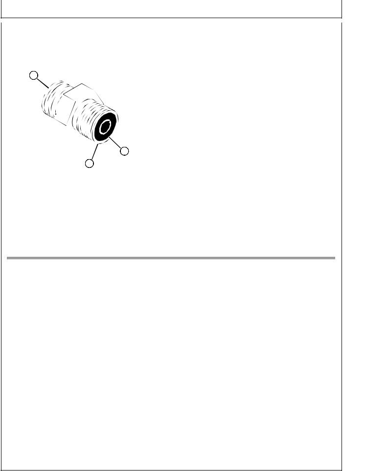
O-RING FACE SEAL FITTINGS |
|
3 |
|
|
|
|
|
Inspect the fitting sealing surfaces (A). They must be |
|
||
1. |
|
||
|
free of dirt or defects. |
|
|
2. |
Inspect the O-ring (B). It must be free of damage or |
|
|
A |
defects. |
|
|
3. |
Lubricate O-rings and install into groove using |
|
|
|
petroleum jelly to hold in place. |
|
|
4. |
Push O-ring into the groove with plenty of petroleum |
|
|
|
jelly so O-ring is not displaced during assembly. |
|
|
5. |
Index angle fittings and tighten by hand pressing joint |
|
|
|
together to insure O-ring remains in place. |
|
|
6. |
Tighten fitting or nut to torque value shown on the |
|
|
|
chart per dash size stamped on the fitting. Do not |
|
|
B |
allow hoses to twist when tightening fittings. |
|
|
|
|
|
|
A |
|
|
|
O-RING FACE SEAL FITTING INCH TORQUE
NOMINAL |
|
THREAD |
SWIVEL NUT |
BULKHEAD |
|||||
|
|
Dash |
|
|
|
|
|
|
|
Tube O.D. |
|
Size |
|
Torque |
Nut Torque |
||||
Size |
|
|
|||||||
|
|
|
|
|
|
|
|
|
|
mm |
in. |
|
|
in. |
N•m |
|
lb-ft |
N•m |
lb-ft |
6.35 |
0.250 |
-4 |
9/16-18 |
16 |
|
12 |
5.0 |
3.5 |
|
|
|
|
|
|
|
|
|
|
|
9.52 |
0.375 |
-6 |
11/16-16 |
24 |
|
18 |
9.0 |
6.5 |
|
|
|
|
|
|
|
|
|
|
|
12.70 |
0.500 |
-8 |
13/16-16 |
50 |
|
37 |
17.0 |
12.5 |
|
|
|
|
|
|
|
|
|
|
|
15.88 |
0.625 |
-10 |
1-14 |
69 |
|
51 |
17.0 |
12.5 |
|
|
|
|
|
|
|
|
|
|
|
19.05 |
0.750 |
-12 |
1 |
3/16-12 |
102 |
|
75 |
17.0 |
12.5 |
|
|
|
|
|
|
|
|
|
|
22.22 |
0.875 |
-14 |
1 |
3/16-12 |
102 |
|
75 |
17.0 |
12.5 |
|
|
|
|
|
|
|
|
|
|
25.40 |
1.000 |
-16 |
1 |
7/16-12 |
142 |
|
105 |
17.0 |
12.5 |
|
|
|
|
|
|
|
|
|
|
31.75 |
1.250 |
-20 |
1 |
11/16-12 |
190 |
|
140 |
17.0 |
12.5 |
|
|
|
|
|
|
|
|
|
|
38.10 |
1.500 |
-24 |
2-12 |
217 |
|
160 |
17.0 |
12.5 |
|
|
|
|
|
|
|
|
|
|
|
NOTE: Torque tolerance is + 15 -20%.
10-15-3

Service Recommendations/O-Ring Boss Fittings
10
15
4
O-RING BOSS FITTINGS
1.Inspect boss O-ring boss seat. It must be free of dirt and defects. If repeated leaks occur, inspect for defects with a magnifying glass. Some raised defects can be removed with a slip stone.
A
B 
2.Put hydraulic oil or petroleum jelly on the O-ring (B). Place electrical tape over the threads to protect O- ring from nicks. Slide O-ring over the tape and into the groove (A) of fitting. Remove tape.
E 
C
D 
3.For angle fittings (C), loosen special nut (E) and push special washer (D) against threads so O-ring can be installed into the groove of fitting.
4.Turn fitting into the boss by hand until special washer or washer face (straight fitting) contacts boss face and O-ring is squeezed into its seat.
5.To position angle fittings, turn the fitting counterclockwise a maximum of one turn.
6.Tighten straight fittings to torque value shown on chart. For angle fittings, tighten the special nut to value shown in the chart while holding body of fitting with a wrench.
STRAIGHT FITTING OR SPECIAL NUT TORQUE
Thread |
Torquea |
Number |
|
|
|
|
|
Size |
N•m |
lb-ft |
of Flatsb |
|
|
|
|
3/8-24 UNF |
8 |
(6) |
2 |
|
|
|
|
7/16-20 UNF |
12 |
(9) |
2 |
|
|
|
|
1/2-20 UNF |
16 |
(12) |
2 |
|
|
|
|
9/16-18 UNF |
24 |
(18) |
2 |
|
|
|
|
3/4-16 UNF |
46 |
(34) |
2 |
|
|
|
|
7/8-14 UNF |
62 |
(46) |
1-1/2 |
|
|
|
|
1-1/16-12 UN |
102 |
(75) |
1 |
|
|
|
|
1-3/16-12 UN |
122 |
(90) |
1 |
|
|
|
|
1-5/16-12 UN |
142 |
(105) |
3/4 |
|
|
|
|
1-5/8-12 UN |
190 |
(140) |
3/4 |
|
|
|
|
1-7/8-12 UN |
217 |
(160) |
1/2 |
|
|
|
|
a.Torque tolerance is ± 10 percent.
b.To be used if a torque wrench cannot be used. After tightening fitting by hand, put a mark on nut or boss; then tighten special nut or straight fitting the number of flats shown.
10-15-4

Group 20
Fuels, Lubricants, and Coolants
DIESEL FUEL - NORTH AMERICA
In general, diesel fuels are blended to satisfy the low air temperature requirements of the geographical area in which they are sold.
In North America, diesel fuel is usually specified to ASTM D975 and sold as either Grade 1 for cold air temperatures or Grade 2 for warm air temperatures.
If diesel fuels being supplied in your area DO NOT meet any of the above specifications, use diesel fuels with the following equivalent properties:
•Cetane Number 40 (minimum)
A cetane number greater than 50 is preferred, especially for air temperatures below –20°C (–4°F) or elevations above 1500 m (5000 ft).
•Cold Filter Plugging Point (CFPP)
The air temperature at which diesel fuel begins to cloud or jell — at least 5°C (9°F) below the expected low air temperature range.
•Sulfur Content of 0.05%
Diesel fuels for highway use in the United States now require sulfur content to be less than 0.05%.
If diesel fuel being used has a sulfur content greater than 0.05%, reduce the service interval for engine oil and filter by 50%.
Consult your local diesel fuel distributor for properties of the diesel fuel available in your area.
c WARNING
California Proposition 65 Warning: Diesel engine exhaust and some of its elements from this product are known to the State of California to cause cancer, birth defects, or other reproductive harm.
10
20
1
DIESEL FUEL LUBRICITY
Diesel fuel must have adequate lubricity to ensure proper operation and durability of fuel injection system components. Fuel lubricity should pass a minimum of 3300 gram load level as measured by the BOCLE scuffing test.
DIESEL FUEL STORAGE
IMPORTANT: DO NOT USE GALVANIZED CONTAINERS—diesel fuel stored in galvanized containers reacts with zinc coating in the container to form zinc flakes. If fuel contains water, a zinc gel will also form. The gel and flakes will quickly plug fuel filters and damage fuel injectors and fuel pumps.
It is recommended that diesel fuel be stored ONLY in a clean, approved POLYETHYLENE PLASTIC container WITHOUT any metal screen or filter. This will help prevent any accidental sparks from occurring. Store fuel in an area that is well ventilated to prevent possible igniting of fumes by an open flame or spark, this includes any appliance with a pilot light.
IMPORTANT: Keep all dirt, scale, water or other foreign material out of fuel.
Keep fuel in a safe, protected area and in a clean, properly marked (“DIESEL FUEL”) container. DO NOT use deicers to attempt to remove water from fuel. DO NOT depend on fuel filters to remove water from fuel. It is recommended that a water separator be installed in the storage tank outlet. BE SURE to properly discard unstable or contaminated diesel fuel and/or their containers when necessary.
10-20-1

Fuels, Lubricants, and Coolants/Hydraulic/Transmission Oil
10
20
2
DIESEL FUEL - EUROPE |
Consult your local diesel fuel distributor for properties of |
|
the diesel fuel available in your area. |
In general, diesel fuels are blended to satisfy the low air |
•Cold Filter Plugging Point (CFPP) |
temperature requirements of the geographical area in |
The air temperature at which diesel fuel begins to |
which they are sold. |
|
|
cloud or jell — at least 5°C (9°F) below the expected |
In Europe, diesel fuel is usually specified to EN590 and |
low air temperature range. |
sold in 5 different classes or 6 different grades. |
•Sulfur Content of 0.05% |
If diesel fuels being supplied in your area DO NOT meet |
Diesel fuel for highway use in the European Union |
any of the above specifications, use diesel fuels with the |
will be required to have a sulfur content of less than |
following equivalent properties: |
0.05% by 1 October 1996. |
•Cetane Number 40 (minimum) |
If diesel fuel being used has a sulfur content greater |
|
|
A cetane number greater than 50 is preferred, |
than 0.05%, reduce the service interval for engine |
especially for air temperatures below –20°C (–4°F) or |
oil and filter by 50%. |
elevations above 1500 m (5000 ft). |
Consult your local diesel fuel distributor for properties of |
|
|
If diesel fuel being used has a sulfur content greater |
the diesel fuel available in your area. |
than 0.05%, reduce the service interval for engine |
|
oil and filter by 50%. |
|
|
|
|
|
DIESEL FUEL LUBRICITY |
|
Diesel fuel must have adequate lubricity to ensure |
|
proper operation and durability of fuel injection system |
|
components. Fuel lubricity should pass a minimum of |
|
3300 gram load level as measured by the BOCLE |
|
scuffing test. |
|
|
|
|
|
DIESEL FUEL STORAGE
IMPORTANT: DO NOT USE GALVANIZED CONTAINERS—diesel fuel stored in galvanized containers reacts with zinc coating in the container to form zinc flakes. If fuel contains water, a zinc gel will also form. The gel and flakes will quickly plug fuel filters and damage fuel injectors and fuel pumps.
It is recommended that diesel fuel be stored ONLY in a clean, approved POLYETHYLENE PLASTIC container WITHOUT any metal screen or filter. This will help prevent any accidental sparks from occurring. Store fuel
in an area that is well ventilated to prevent possible igniting of fumes by an open flame or spark, this includes any appliance with a pilot light.
IMPORTANT: Keep all dirt, scale, water or other foreign material out of fuel.
Keep fuel in a safe, protected area and in a clean, properly marked (“DIESEL FUEL”) container. DO NOT use deicers to attempt to remove water from fuel. DO NOT depend on fuel filters to remove water from fuel. It is recommended that a water separator be installed in the storage tank outlet. BE SURE to properly discard unstable or contaminated diesel fuel and/or their containers when necessary.
10-20-2
Fuels, Lubricants, and Coolants/Hydraulic/Transmission Oil
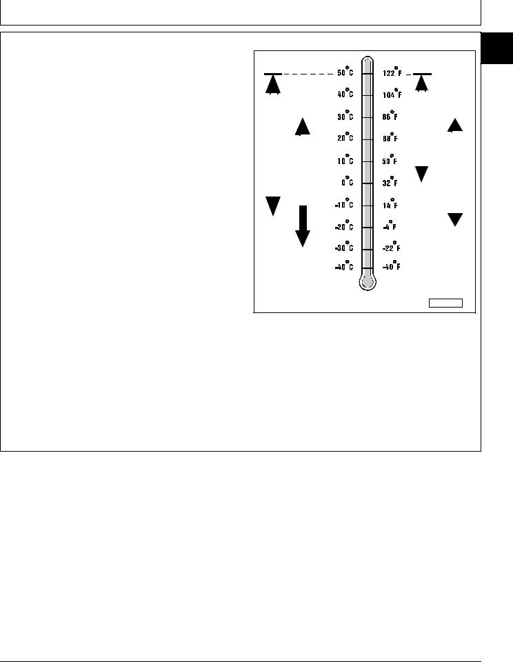
4–CYCLE DIESEL ENGINE OIL - NORTH AMERICA
Use appropriate oil viscosity based on the expected air temperature range during the period between recommended oil changes. Operating outside of these recommended oil air temperature ranges may cause premature engine failure.
The following John Deere oils are PREFERRED:
•PLUS–50®—SAE 15W-40;
•TORQ–GARD SUPREME®—SAE 5W-30 .
The following John Deere oils are also recommended, based on their specified temperature range:
•TURF–GARD®—SAE 10W-30;
•PLUS–4®—SAE 10W-30;
•TORQ–GARD SUPREME®—SAE 30.
Other oils may be used if above John Deere oils are not available, provided they meet one of the following specifications:
•SAE 15W-40 (preferred)—API Service Classifications CG–4 or CF–4 or higher;
•SAE 5W-30 (preferred)—API Service Classification CD or CC or higher;
•SAE 10W-30—API Service Classification CF–4 or CF or higher;
•SAE 30—API Service Classification CF–4 or CF or higher.
IMPORTANT: If diesel fuel with sulfur content greater than 0.5% is used, reduce the service interval for oil and filter by 50%.
10
20
3
|
|
|
|
|
|
|
|
|
|
|
|
|
|
|
|
|
|
|
|
|
|
|
|
|
|
|
|
|
|
|
|
|
|
|
|
|
|
|
|
|
|
|
|
|
|
|
|
|
|
|
|
|
|
|
|
|
|
|
|
|
|
|
|
|
|
|
|
|
|
|
|
|
|
|
|
|
|
|
|
|
|
|
|
|
|
|
|
|
|
|
|
|
|
|
|
|
|
<![if ! IE]> <![endif]>SAE 30 |
|
|
|
|
|
|
|
|
|
|
||
|
<![if ! IE]> <![endif]>15W-40 |
|
|
|
|
|
|
|
|
|
|
|
|
|
|
|
|
|
|
|
|
|
|
|
|
|
|
|
|
|
||||||
|
|
|
|
|
|
|
|
|
|
|
|
|
|
|
|
|
|
|
|
|
|
|
|
|
|
|
|
|||||||||
|
|
|
|
|
|
|
|
|
|
|
|
|
|
|
|
|
|
|
|
|
|
|
|
|
|
|
|
|
|
|
|
|
|
|
||
|
<![if ! IE]> <![endif]>SAE |
|
|
|
|
|
|
|
|
|
|
|
|
|
|
|
|
|
|
|
|
|
|
|
|
|
|
|
|
|
<![if ! IE]> <![endif]>SAE10W-30 |
|||||
|
|
|
|
|
|
|
<![if ! IE]> <![endif]>SAE 5W-30 |
|
|
|
|
|
|
|
|
|
|
|
|
|
|
|
|
|
|
|||||||||||
|
|
|
|
|
|
|
|
|
|
|
|
|
|
|
|
|
|
|
|
|
|
|
|
|
||||||||||||
|
|
|
|
|
|
|
|
|
|
|
|
|
|
|||||||||||||||||||||||
|
|
|
|
|
|
|
|
|
|
|
|
|
|
|
|
|
|
|
|
|
|
|
|
|
||||||||||||
|
|
|
|
|
|
|
|
|
|
|
|
|
|
|
|
|
|
|
|
|
|
|
|
|
|
|
|
|||||||||
|
|
|
|
|
|
|
|
|
|
|
|
|
|
|
|
|
|
|
|
|
|
|
||||||||||||||
|
|
|
|
|
|
|
|
|
|
|
|
|
|
|
|
|
|
|
|
|
|
|
|
|
|
|
|
|
|
|
|
|
|
|
|
|
|
|
|
|
|
|
|
|
|
|
|
|
|
|
|
|
|
|
|
|
|
|
|
|
|
|
|
|
|
|
|
|
|
|
|
|
|
|
|
|
|
|
|
|
|
|
|
|
|
|
|
|
|
|
|
|
|
|
|
|
|
|
|
|
|
|
|
|
|
|
|
|
|
|
|
|
|
|
|
|
|
|
|
|
|
|
|
|
|
|
|
|
|
|
|
|
|
|
|
|
|
|
|
|
|
|
|
|
|
|
|
|
|
|
|
|
|
|
|
|
|
|
|
|
|
|
|
|
|
|
|
|
|
|
|
|
|
|
|
|
|
|
|
|
|
|
|
|
|
|
|
|
|
|
|
|
|
|
|
|
|
|
|
|
|
|
|
|
|
|
|
|
|
|
|
|
|
|
|
|
|
|
|
|
|
PREFERRED
AIR TEMPERATURE
M58275
John Deere Dealers: You may want to cross-reference the following publications to recommend the proper oil for your customers:
•Module DX, ENOIL in JDS–G135;
•Section 530, Lubricants & Hydraulics, of the John Deere Merchandise Sales Guide;
•Lubrication Sales Manual PI7032.
10-20-3
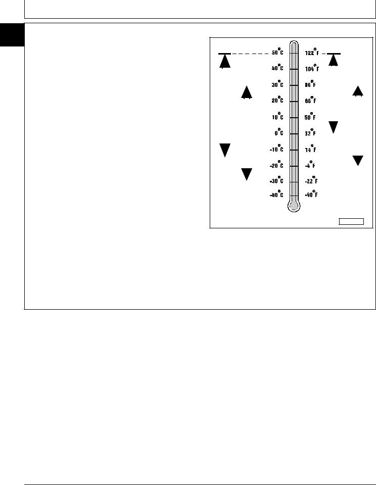
Fuels, Lubricants, and Coolants/Hydraulic/Transmission Oil
10
20 4–CYCLE DIESEL ENGINE OIL - EUROPE
4
Use appropriate oil viscosity based on the expected air temperature range during the period between recommended oil changes. Operating outside of these recommended oil air temperature ranges may cause premature engine failure.
The following John Deere oils are PREFERRED:
•TORQ–GARD SUPREME®—SAE 15W-40;
•UNI–GARD™—SAE 15W-40;
•TORQ–GARD SUPREME®—SAE 5W-30;
•UNI–GARD™—SAE 5W-30.
The following John Deere oils are also recommended, based on their specified temperature range:
•TORQ–GARD SUPREME®—SAE 10W-30;
•UNI–GARD™—SAE 10W-30;
•TORQ–GARD SUPREME®—SAE 30;
•UNI–GARD™—SAE 30.
Other oils may be used if above John Deere oils are not available, provided they meet one of the following specifications:
•CCMC Specification D5 or Mercedes Benz MB228.3 or higher;
•CCMC Specification D4 or Mercedes Benz MB228.1 or higher.
IMPORTANT: If diesel fuel with sulfur content greater than 0.5% is used, reduce the service interval for oil and filter by 50%.
|
|
|
|
|
|
|
|
|
|
|
|
|
|
|
|
|
|
|
|
|
|
|
|
|
|
|
|
|
|
|
|
|
|
|
|
|
|
|
|
|
|
|
|
|
|
|
|
|
|
|
|
|
|
|
|
|
|
|
|
|
|
|
|
|
|
|
|
|
|
|
|
|
|
|
|
|
|
|
|
|
|
|
|
|
|
|
|
|
|
|
|
|
|
|
|
|
|
<![if ! IE]> <![endif]>SAE 30 |
|
|
|
|
|
|
|
|
|
|
||
|
<![if ! IE]> <![endif]>15W-40 |
|
|
|
|
|
|
|
|
|
|
|
|
|
|
|
|
|
|
|
|
|
|
|
|
|
|
|
|
|
||||||
|
|
|
|
|
|
|
|
|
|
|
|
|
|
|
|
|
|
|
|
|
|
|
|
|
|
|
|
|||||||||
|
|
|
|
|
|
|
|
|
|
|
|
|
|
|
|
|
|
|
|
|
|
|
|
|
|
|
|
|
|
|
|
|
|
|
||
|
<![if ! IE]> <![endif]>SAE |
|
|
|
|
|
|
|
|
|
|
|
|
|
|
|
|
|
|
|
|
|
|
|
|
|
|
|
|
|
<![if ! IE]> <![endif]>SAE10W-30 |
|||||
|
|
|
|
|
|
|
<![if ! IE]> <![endif]>SAE 5W-30 |
|
|
|
|
|
|
|
|
|
|
|
|
|
|
|
|
|
|
|||||||||||
|
|
|
|
|
|
|
|
|
|
|
|
|
|
|
|
|
|
|
|
|
|
|
|
|
||||||||||||
|
|
|
|
|
|
|
|
|
|
|
|
|
|
|||||||||||||||||||||||
|
|
|
|
|
|
|
|
|
|
|
|
|
|
|
|
|
|
|
|
|
|
|
|
|
||||||||||||
|
|
|
|
|
|
|
|
|
|
|
|
|
|
|
|
|
|
|
|
|
|
|
|
|
|
|
|
|||||||||
|
|
|
|
|
|
|
|
|
|
|
|
|
|
|
|
|
|
|
|
|
|
|
||||||||||||||
|
|
|
|
|
|
|
|
|
|
|
|
|
|
|
|
|
|
|
|
|
|
|
|
|
|
|
|
|
|
|
|
|
|
|
|
|
|
|
|
|
|
|
|
|
|
|
|
|
|
|
|
|
|
|
|
|
|
|
|
|
|
|
|
|
|
|
|
|
|
|
|
|
|
|
|
|
|
|
|
|
|
|
|
|
|
|
|
|
|
|
|
|
|
|
|
|
|
|
|
|
|
|
|
|
|
|
|
|
|
|
|
|
|
|
|
|
|
|
|
|
|
|
|
|
|
|
|
|
|
|
|
|
|
|
|
|
|
|
|
|
|
|
|
|
|
|
|
|
|
|
|
|
|
|
|
|
|
|
|
|
|
|
|
|
|
|
|
|
|
|
|
|
|
|
|
|
|
|
|
|
|
|
|
|
|
|
|
|
|
|
|
|
|
|
|
|
|
|
|
|
|
|
|
|
|
|
|
|
|
|
|
|
|
|
|
|
|
|
|
|
|
PREFERRED
AIR TEMPERATURE
M58275
John Deere Dealers: You may want to cross-reference the following publications to recommend the proper oil for your customers:
•Module DX,ENOIL in JDS–G135;
•Section 530, Lubricants & Hydraulics, of the John Deere Merchandise Sales Guide.
10-20-4

Fuels, Lubricants, and Coolants/Hydraulic/Transmission Oil
BREAK–IN DIESEL ENGINE OIL - NORTH AMERICA
IMPORTANT: ONLY use this specified break-in oil in rebuilt or remanufactured engines for the first 100 hours maximum. DO NOT use PLUS–50®, SAE 15W40 oil or oils meeting specifications API CG–4 or API CF–4, these oils will not allow rebuilt or remanufactured engines to break-in properly.
The following John Deere oil is PREFERRED:
•BREAK–IN ENGINE OIL .
John Deere BREAK–IN ENGINE OIL is formulated with special additives for aluminum and cast iron type engines to allow the power cylinder components (pistons, rings, and liners as well) to “wear-in” while protecting other engine components, valve train and gears, from abnormal wear. Engine rebuild instructions should be followed closely to determine if special requirements are necessary.
John Deere BREAK–IN ENGINE OIL is also recommended for non-John Deere engines, both aluminum and cast iron types.
If this preferred John Deere oil is not available, use a break-in engine oil meeting the following specification during the first 100 hours of operation:
•API Service Classification CE.
After the break-in period, use the John Deere oil that is recommended for this engine.
10
20
5
<![if ! IE]><![endif]>BREAK-IN OIL
AIR TEMPERATURE
M58275
John Deere Dealers: You may want to cross-reference the following publications to recommend the proper oil for your customers:
•Module DX,ENOIL4 in JDS–G135;
•Section 530, Lubricants & Hydraulics, of the John Deere Merchandise Sales Guide;
•Lubrication Sales Manual PI7032.
10-20-5

Fuels, Lubricants, and Coolants/Hydraulic/Transmission Oil
10
20
6
BREAK–IN DIESEL ENGINE OIL - EUROPE
IMPORTANT: ONLY use this specified break-in oil in rebuilt or remanufactured engines for the first 100 hours maximum. DO NOT use SAE 15W-40 oil or oils meeting CCMC Specification D5—these oils will not allow rebuilt or remanufactured engines to break-in properly.
The following John Deere oil is PREFERRED:
•BREAK–IN ENGINE OIL .
John Deere BREAK–IN ENGINE OIL is formulated with special additives for aluminum and cast iron type engines to allow the power cylinder components (pistons, rings, and liners as well) to “wear-in” while protecting other engine components, valve train and gears, from abnormal wear. Engine rebuild instructions should be followed closely to determine if special requirements are necessary.
John Deere BREAK–IN ENGINE OIL is also recommended for non-John Deere engines, both aluminum and cast iron types.
If above preferred John Deere oil is not available, use a break-in engine oil meeting the following specification during the first 100 hours of operation:
•CCMC Specification D4.
After the break-in period, use the John Deere oil that is recommended for this engine.
<![endif]>BREAK-IN OIL
AIR TEMPERATURE
M58275
John Deere Dealers: You may want to cross-reference the following publications to recommend the proper oil for your customers:
•Module DX, ENOIL4 in JDS–G135;
•Section 530, Lubricants & Hydraulics, of the John Deere Merchandise Sales Guide.
10-20-6
Loading...