


AC-3500GSH
®
C US
201473
AC-3500GHH
AC-3500GSH
HOT WATER PRESSURE WASHERS
John Deere Operator's Manual 1
CAUTION
RISK OF INJURY!
READ MANUAL BEFORE OPERATING!
This manual is an important part of the pressure washer and must
remain with the unit when you sell or rent it!
TABLE OF CONTENTS
INTRODUCTION ............................................................................................................................. 3
IMPORTANT SAFETY WARNINGS.............................................................................................4-7
RISK OF EXPLOSION OR FIRE ........................................................................................4
RISK OF ASPHYXIATION ..................................................................................................5
RISK OF INJECTION OR SEVERE CUTTING INJURY .....................................................5
RISK OF ELECTROCUTION OR ELECTRICAL SHOCK ...................................................5
RISK OF BURNS ................................................................................................................6
RISK OF BURSTING ..........................................................................................................6
RISK FROM MOVING PARTS ............................................................................................6
RISK OF BODILY INJURY ..................................................................................................7
FEATURES ................................................................................................................................8-10
INSTALLATION & PREPARATION .............................................................................................. 10
ATTIRE .............................................................................................................................10
SET-UP .............................................................................................................................10
ENGINE/BURNER FUEL TANK ........................................................................................10
ADJUSTABLE PRESSURE DUAL LANCE ....................................................................... 11
DUAL LANCE CONNECTION .......................................................................................... 11
` WATER SUPPLY ...............................................................................................................11
UNLOADER ......................................................................................................................12
HEAT DUMP VALVE .........................................................................................................12
PRE-START INSPECTION PROCEDURES .....................................................................12
OPERATING INSTRUCTIONS ................................................................................................14-15
PRIMING THE PUMP .......................................................................................................14
START-UP/COLD WATER OPERATION ..........................................................................14
HOT WATER OPERATION ...............................................................................................15
CLEANING WITH DETERGENTS UNDER LOW PRESSURE ........................................ 15
SHUTDOWN .....................................................................................................................15
STORAGE & MAINTENANCE ................................................................................................. 16-17
SPECIFIC MAINTENANCE .............................................................................................16
WINTERIZING ..................................................................................................................17
TROUBLESHOOTING ............................................................................................................. 18-19
MAINTENANCE CHART ..............................................................................................................20
ACCESSORIES ............................................................................................................................21
STATEMENT OF WARRANTY .....................................................................................................22
NOTES .......................................................................................................................................... 23
PROTECT YOUR INVESTMENT......
Use only John Deere Fuel Protect
Fuel Stabilizer with Ethanol Protection
TY27534 or TY27535. Developed to
ensure Optimum Performance and
Protection.
IMPORTANT...Use Year Round!
34-1904 012011
Warning: This product contains lead, a
chemical known to the State of California
to cause birth defects or other reproductive
harm.
Wash your hands after handling this product.
2 John Deere Operator's Manual
INTRODUCTION
Congratulations on the purchase of your new John Deere hot water pressure washer featuring the patented Electro
Magnetic Firing (EMF) System! You can be assured your John Deere hot water pressure washer was constructed and
designed with quality and performance in mind. Each component has been rigorously tested to ensure the highest level
of acceptance.
This operator's manual was compiled for your benet. By reading and following the simple safety, installation, operation,
maintenance and troubleshooting steps described in this manual, you will receive years of trouble free operation from
your new John Deere hot water pressure washer. The contents of this manual are based on the latest product information
available at the time of publication. John Deere reserves the right to make changes in price, color, materials, equipment,
specications or models at any time without notice.
! IMPORTANT !
These paragraphs are surrounded by a "SAFETY ALERT BOX". This box is used to designate
and emphasize Safety Warnings that must be followed when operating this pressure washer.
Accompanying the Safety Warnings are "signal words" which designate the degree or level
of hazard seriousness. The "signal words" used in this manual are as follows:
DANGER: Indicates an imminently hazardous situation which, if not avoided, WILL
result in death or serious injury.
WARNING: Indicates a potentially hazardous situation which, if not avoided, COULD
result in death or serious injury.
CAUTION: Indicates a potentially hazardous situation which, if not avoided MAY
result in minor or moderate injury.
The symbols set to the left of this paragraph are "Safety Alert Symbols". These symbols
are used to call attention to items or procedures that could be dangerous to you or other
persons using this equipment.
ALWAYS PROVIDE A COPY OF THIS MANUAL TO ANYONE USING THIS EQUIPMENT. READ
ALL INSTRUCTIONS BEFORE OPERATING THIS PRESSURE WASHER AND ESPECIALLY
POINT OUT THE "SAFETY WARNINGS" TO PREVENT THE POSSIBILITY OF PERSONAL
INJURY TO THE OPERATOR.
Once the unit has been uncrated, immediately write in the serial number of your unit in the space provided below.
SERIAL NUMBER_________________________________
Inspect for signs of obvious or concealed freight damage. If damage does exist, le a claim with the transportation
company immediately. Be sure that all damaged parts are replaced an that the mechanical and electrical problems are
corrected prior to operation of the unit. If you require service, contact your Customer Service.
Mi-T-M® Corporation, 8650 Enterprise Drive, Peosta, IA 52068
1-877-JD-KLEEN / (1-877-535-5336) Fax 319-556-1235
Monday - Friday 8:00 a.m. - 5:00 p.m. CST
1. Model Number
2. Serial Number
3. Date and Place of Purchase
Please have the following information available for all service calls:
John Deere Operator's Manual 3

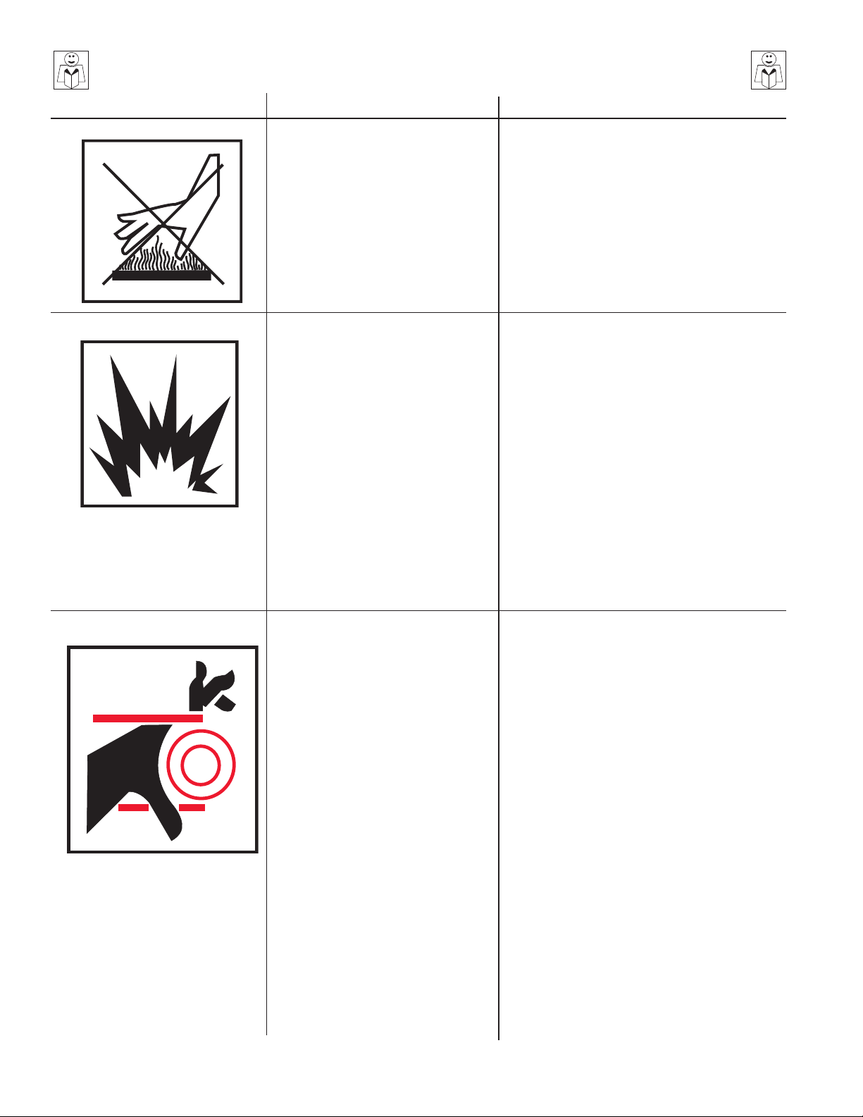
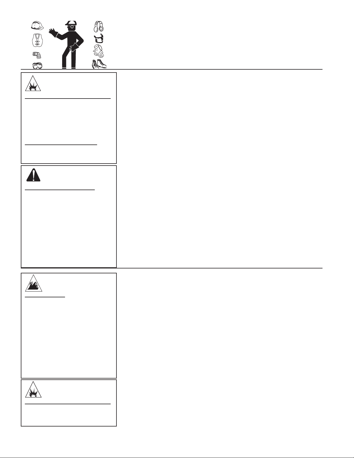
SAFETY WARNINGS
WARNING: When using this product, basic precautions should always be observed, including the following.
READ ALL SAFETY WARNINGS BEFORE USING PRESSURE WASHER
HAZARD
RISK OF
EXPLOSION OR FIRE
POTENTIAL CONSEQUENCE
Serious injury or death may occur
from normal sparks in the multiple
ignition sources or engine/burner
exhaust.
PREVENTION
Always operate pressure washer in a well
ventilated area free of ammable vapors,
combustible dust, gases or other combustible
materials.
Do not store the pressure washer near an
open ame or any equipment such as a stove,
furnace, water heater, etc., which utilizes a pilot
light or sparking device.
Do not use this pressure washer to spray
ammable material!
Serious injury or death may occur as
a result of improper fueling.
Serious injury or death may occur
from a ground re caused by a
mufer spark.
Do not smoke while lling fuel tanks.
Never ll the fuel tanks while the engine is
running or hot. Allow the engine to cool two
minutes before refueling.
Do not refuel indoors or in a poorly ventilated
area.
Always refuel slowly to avoid the possibility of
spilled fuel which may cause a risk of re.
Engine Fuel Tank: If using a Gasoline Engine,
refuel with gasoline only. Do not use diesel
or fuel oil.
Burner Fuel Tank (Black): When refueling
the Burner Fuel Tank, use No. 1 or No. 2 fuel
oil/diesel or kerosene. Do not use gasoline.
Do not operate the unit if gasoline or diesel
fuel is spilled. Wipe the pressure washer
clean and move it away from the spill. Avoid
creating any ignition until the gasoline or diesel
fuel has evaporated.
A spark arrester must be added to the mufer
of this engine if it is to be used on any forest
covered, brush covered or grass covered
unimproved land. The arrester must be
maintained in effective working order by the
operator. In the state of California, the above is
required by law. (Section 4442 of the California
Public Resources Code.) Other states may
have similar laws. Federal laws apply on
Federal lands.
Serious injury or death may occur
if system safety's are not properly
maintained.
4 John Deere Operator's Manual
This pressure washer has a Safety Relief
device which should never be altered, modied,
removed or made inoperative. If the device
fails, replace immediately with only genuine
manufacturer replacement part.
SAFETY WARNINGS
READ ALL SAFETY WARNINGS BEFORE USING PRESSURE WASHER
HAZARD
RISK OF
ASPHYXIATION
RISK OF INJECTION OR
SEVERE CUTTING INJURY
POTENTIAL CONSEQUENCE
Serious injury or death may occur
from inhaling engine/burner exhaust
or dangerous vapors. The engine
exhaust from this product contains
chemicals known to the State of
California to cause cancer, birth
defects, or other reproductive
harm.
Serious injury or death could occur
from high pressure spray penetrating
the skin.
PREVENTION
This pressure washer was designed for outdoor
use only. Never operate this pressure washer
in an enclosed area. Always make certain there
is adequate ventilation (fresh outside air) for
breathing and combustion. This will prevent
the buildup of dangerous carbon monoxide
gases. Beware of poorly ventilated areas, or
areas with exhaust fans which can cause poor
air exchange.
Follow all safety instructions provided with the
materials you are spraying. Use of a respirator
may be required when working with some
materials. Do not use this pressure washer
to dispense hazardous detergents.
Keep clear of nozzle and spray! Never put
your hand, ngers or body directly over the
spray nozzle.
Never point the high pressure discharge spray
at yourself or anyone else.
Always keep operating area clear of all
persons.
DO NOT allow children to operate this unit.
SEEK EMERGENCY MEDICAL CARE if the
spray appears to have penetrated the skin!
DO NOT TREAT AS A SIMPLE CUT!!
High pressure hoses and fuel lines should be
inspected daily for signs of wear. If evidence
of failure exists, promptly replace all suspect
hoses and fuel lines to prevent the possibility of
injury from the high pressure spray. If a hose
or tting is leaking, NEVER PLACE YOUR
HAND DIRECTLY ON THE LEAK.
NEVER operate the gun with the trigger wired
in the open position. To prevent accidental
discharge, the trigger gun should be securely
locked when not in use.
Before removing the spray nozzle or servicing
the unit, ALWAYS shut off the unit and trigger
the gun to release trapped pressure. (Even
after you shut off the unit, there is high
pressure water left in the pump, hose and gun
until you release it by triggering the gun.)
RISK OF
ELECTROCUTION OR
ELECTRICAL SHOCK
John Deere Operator's Manual 5
Serious injury or death may occur
from contact with electricity.
DO NOT direct spray on or into electrical
installations of any kind! This includes
electrical outlets, light bulbs, fuse boxes,
transformers, the unit itself, etc.
DO NOT allow metal components of the
pressure washer to come in contact with live
electrical components.
SAFETY WARNINGS
READ ALL SAFETY WARNINGS BEFORE USING PRESSURE WASHER
HAZARD
RISK OF BURNS
RISK OF BURSTING
POTENTIAL CONSEQUENCE
Serious injury may occur from
touching the gasoline engine,
mufer or heat exchanger. These
areas can remain hot for some
time after the pressure washer is
shutdown.
Serious injury may occur from a
pressure washer malfunction or
exploding accessories if incorrect
system components, attachments
or accessories are used.
Serious injury or death may occur
if attempting to start the pressure
washer when the pump is frozen.
PREVENTION
Never allow any part of your body to contact the
gasoline engine, mufer or heat exchanger.
Never make adjustments to the factory set
pressures.
Never exceed manufacturers maximum
allowable pressure rating of attachments.
Do not allow any hoses to make contact with
the engine mufer, gasoline engine or heat
exchanger to prevent the possibility of bursting.
Avoid dragging the hoses over abrasive
surfaces such as cement.
Use only John Deere recommended repair
parts for your pressure washer.
In freezing temperatures, the unit must always
be warm enough to ensure there is no ice
formation in the pump. Do not start the pressure
washer if it has been transported in an open
or underheated vehicle without rst allowing
the pump to thaw.
RISK FROM MOVING PARTS
Serious injury may occur to the
operator from moving parts on the
pressure washer.
Before making any adjustments, be certain
the engine is turned off and the ignition
cable(s) is removed from the spark plug(s).
Turning the machinery over by hand during
adjustment or cleaning might start the engine
and machinery with it.
Do not operate the unit without all protective
covers in place.
6 John Deere Operator's Manual

SAFETY WARNINGS
READ ALL SAFETY WARNINGS BEFORE USING PRESSURE WASHER
HAZARD
RISK OF BODILY INJURY
POTENTIAL CONSEQUENCE
Serious injury or death may occur
from detergents contacting the
skin.
Serious injury can occur from loose
debris being propelled at a high
speed from the spray gun.
Injury may occur if the operator loses
his balance caused by the thrust of
water traveling through the spray
nozzle.
Injury may occur from the pressure
washer.
PREVENTION
SEEK EMERGENCY MEDICAL CARE if you are
using cleaning agents and the spray appears to
have penetrated the skin! DO NOT TREAT AS
A SIMPLE CUT! Be prepared to tell a physician
exactly what kind of detergents you were using by
reading the Material Safety Data Sheet (MSDS)
provided with your detergent.
Never use any solvents or highly corrosive
detergents or acid type cleaners with this
pressure washer.
Protective equipment such as rubber suits,
gloves and respirators are advisable, especially
when using cleaning detergents.
Keep all detergents out of the reach of
children!
ALWAYS wear protective goggles when
operating the unit to shield the eyes from ying
debris and detergents.
DO NOT direct spray toward fragile materials
such as glass for shattering could occur.
Stay alert-watch what you are doing. Do not
operate the unit when fatigued or under the
inuence of alcohol or drugs.
NEVER squeeze the trigger unless securely
braced.
DO NOT overreach or stand on unstable
support.
Wet surfaces can be slippery, wear protective
foot gear and keep good footing and balance
at all times.
NEVER trigger the gun while on a ladder or
roof.
ALWAYS hold on firmly to the gun/lance
assembly when starting and operating the unit.
Failure to do so can cause the lance to fall and
whip dangerously.
Know how to stop the pressure washer and
bleed pressures quickly. Be thoroughly familiar
with controls.
DO NOT leave pressurized unit unattended.
Shut off the pressure washer and release trapped
pressure before leaving.
DO NOT operate the unit if you see any fuel, oil or
water leaks from the machine. DO NOT resume
operation until the unit has been inspected and
repaired by a qualied service person.
NEVER run the engine with the governor
disconnected or operate at excessive speeds.
Place unit in a clean, dry, at area for servicing.
Before servicing the unit: turn the unit off, relieve
the water pressure from the trigger gun, and
allow the unit to cool down. Service in clean,
dry, at area. If applicable, block wheels to
prevent unit from moving.
Do not move the unit by pulling on the hose.
!SAVE THESE INSTRUCTIONS!
John Deere Operator's Manual 7
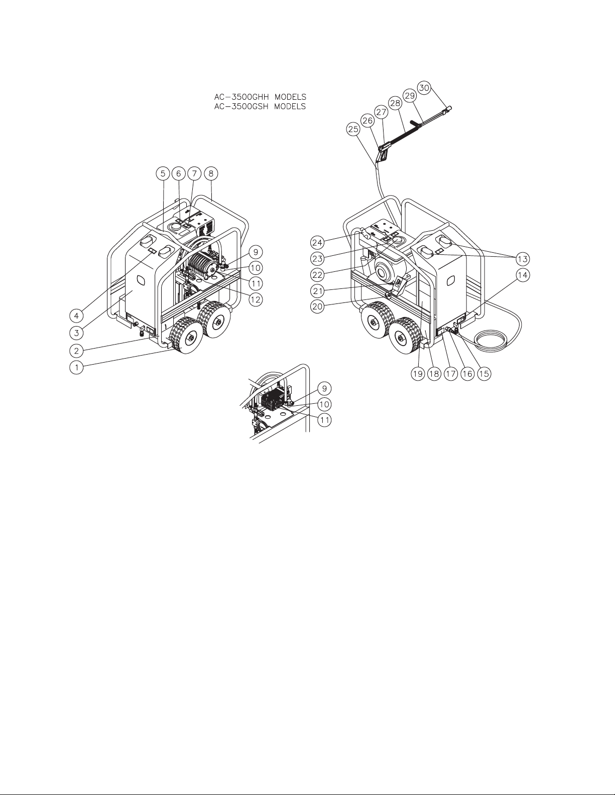
HSP-LARGE FRAME FEATURES
HSP-LARGE FEATURES 061209
8 John Deere Operator's Manual

FEATURES LISTING
1. Pneumatic Wheels
2. Protective Rollcage
3. Protective Cover
4. Decal-Warning: Hot Surfaces
5. Center Balanced Lifting Eye
6. Decal-Caution: Cool before Refueling
7. Decal- Warning: Allow to Cool
8. Convenient Push/Pull Handle
9. Water Inlet
10. Water Strainer
11. High Pressure Pump
12. Beltguard
13. Heat Exchanger Exhaust
14. Decal-Warning: Do Not Modify Plumbing
15. Coil Drain Assembly
16. High Pressure Outlet
17. Decal-Data Plate
18. Burner Fuel Tank
19. Decal-Warning/Caution/Operating
20. Air Shutter Adjusting Arm
21. Burner On/Off Switch
22. Engine Gasoline Tank
23. Decal-Caution: Risk of Fire
24. Wand Holder
25. High Pressure Hose
26. Trigger Safety Lock
27. Trigger Gun
28. Insulated Lance
29. Adjustable Pressure Dual Lance
30. Nozzle
SPECIFIC UNIT INFORMATION
BODY/FRAME: One piece, welded construction, full roll cage with solid steel axles,
lifting hook and convenient push/pull handle, protective steel housing cover.
PORTABILITY: Four pneumatic tires for easy mobility.
FINISH: Powder Coated
HIGH PRESSURE HOSE: 3/8" x 50'
TRIGGER GUN ASSEMBLY: Trigger controlled, safety lockoff, insulated lance.
DUAL LANCE: Dual Lance, Insulated, w/adjustable pressure.
John Deere Operator's Manual 9
DANGER
RISK OF EXPLOSION OR FIRE!
DO NOT PLACE UNIT IN AN
AREA WHERE FLAMMABLE
GAS VAPORS MAY BE PRESENT.
A SPARK COULD CAUSE AN
EXPLOSION OR FIRE!
RISK OF UNIT BURSTING!
DO NOT STORE/OPERATE UNIT
IN FREEZING ENVIRONMENTS!
WARNING
RISK OF ASPHYXIATION!
DO NOT OP E RATE IN AN
ENCLOSED AREA. USE THIS
PRODU CT ONLY IN WELL
VENTILATED AREAS!
INSTALLATION & PREPARATION
ATTIRE:
Proper attire is essential to your safety. It is advised to utilize whatever means
necessary to protect eyes, ears, and skin. Additional safety attire (such as
respiratory mask) may be required when using detergent cleaning agents with
this washer.
SET-UP:
1. This unit should only be placed on a level surface to ensure proper lubrication
for the engine and water pump while operating. NEVER spray water directly
on the unit.
2. Do not use unit in an area:
a. with insufcient ventilation.
b. where there is evidence of oil or gas leaks.
c. where ammable gas vapors may be present.
This unit has multiple ignition sources that could cause an explosion or
re.
3. Be certain to block the wheels to prevent the unit from moving while
operating.
4. Do not allow the unit to be exposed to rain, snow or freezing temperatures.
If any part of the unit becomes frozen, excessive pressure may build up in
the unit which could cause it to burst resulting in possible serious injury to
the operator or bystanders.
5. Pump oil level should be checked before each use. Check the oil level
indicator on the pump crankcase. Make certain the oil is in the center of the
oil sight glass. If the level appears to be low, ll with John Deere pump oil
SAE 20 or 30.
THE EXHAU S T CON TAIN S
C AR B O N M O N OX I D E, A
POISONOUS, ODORLESS AND
INVISIBLE GAS. BREATHING
THIS GAS CAN CAUSE SERIOUS
INJURY, ILLNESS & POSSIBLE
DEATH.
DANGER
RISK OF FIRE!
-D O NO T SM OK E WH IL E
FUELING!
-DO NOT FILL THE FUEL TANK
WHILE UNIT IS RUNNING OR
HOT. ALLOW UNIT & ENGINE
TO COOL FOR TWO MINUTES
BEFORE REFUELING.
-DO NOT FILL FUEL TANK TO
POINT OF OVERFLO W I NG.
ALLOW APPROXIMATELY 1/4"
OF TANK SPACE FOR FUEL
EXPANSION.
WARNING
ENGINE/BURNER FUEL TANK:
1. Review "Risk of Explosion or Fire" Warnings pg. 4, before fueling.
2. Locate the Safety Decals on your unit and heed their warnings.
3. Gasoline Engines: When lling tank, gasoline fuel should be a minimum
of 85 octane. DO NOT MIX OIL WITH GASOLINE. Gasoline fuel should
be purchased in quantities that may be used within 30 days. Use of clean,
fresh lead-free gasoline is recommended. Leaded gasoline may be used
if lead-free is unavailable. DO NOT use gasoline containing methanol or
alcohol.
Burner Fuel: When lling tank, use No. 1 or No 2 fuel oil/diesel or
kerosene.
4. Check the engine oil level before starting the engine. (See Engine
manual.)
5. Refer to the Engine Manual supplied with this unit for proper engine adjustment
procedures.
6. Review the engine manual accompanying this pressure washer for
correct engine start-up and maintenance procedures.
RISK OF EXPLOSION OR FIRE!
ALWAYS STORE FUEL AWAY
FROM THE WASHER WHILE THE
UNIT IS RUNNING OR HOT.
10 John Deere Operator's Manual
INSTALLATION & PREPARATION
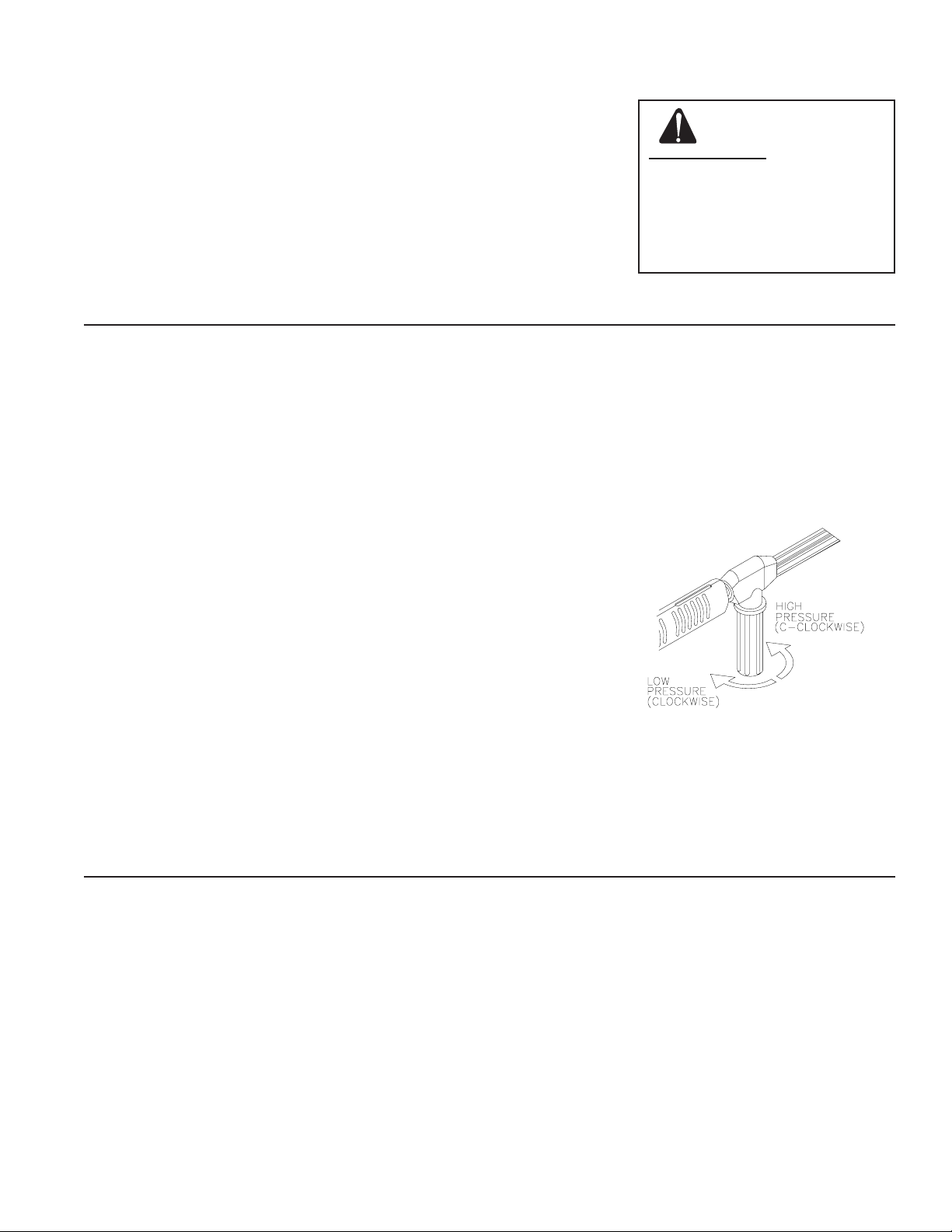
DUAL LANCE ASSEMBLY WITH ADJUSTABLE PRESSURE:
This unit features a Dual Lance Assembly with adjustable pressure which
allows the user to select a high or low pressure "fan" spray. Simply rotate
the adjustable grip on the dual lance to achieve the desired pressure
selection.
1. Selection of high pressure can be achieved by turning the adjustable grip
on the Dual Lance assembly counterclockwise as shown in the gure
below.
2. Selection of low pressure detergent application can be achieved by turning
the adjustable grip on the Dual Lance clockwise as shown in the gure
below. Once the pressure is low enough, the detergent injector on the
pressure washer will draw detergent into the system. A water/detergent
mixture exits from both the spray nozzle and detergent nozzle.
DUAL LANCE CONNECTION:
1. Be certain the trigger gun is locked in the "OFF" position.
2. Connect the dual lance assembly to the trigger gun assembly at this time.
Be certain the connection is securely tightened.
WARNING
RISK OF INJECTION CAUSING
SEVERE INJURY!
-THE T RIGGE R GUN SHOUL D
ALWAYS BE LOCKED IN THE OFF
POSITION WHEN NOT IN USE!
-NEV ER LOO K DIRE CTLY AT
THE NO Z ZLE UNLE SS IT IS
DIS CON NEC TED F ROM T H E
TRIG G ER GUN/ DU AL LANCE
ASSEMBLY!
WATER SUPPLY:
1. Select a water supply hose which is a quality grade of garden hose
measuring at least 3/4" ID and no longer than 50 feet.
2 Check the water inlet strainer to ensure it is clean and free of any
obstructions. As a strainer becomes obstructed, it restricts proper ow of
water to the pump. This can result in cavitations which will prematurely
cause failure of pump packings.
a. Unscrew the strainer cap from the unit.
b. Remove the strainer screen and clean, or replace.
3. Connect one end of the water supply hose to the water inlet of the unit.
Connect the other end of the hose to your pressurized water supply.
NOTE: When connecting the water inlet to the water supply mains, local
regulations of your water company must be observed. In some
areas, the unit must not be connected directly to the public drinking
water supply. This is to ensure there is no feedback of detergents
into the water supply. (Direct connection is permitted if a backow
preventer is installed. Check with local authorities for approval.)
NOTE: If the mineral content of the water in your area is extremely high, the
use of a water softener is recommended to prevent the possibility of
excessive scale buildup inside the heat exchanger coil.
4. Follow the incoming water requirements listed below:
a. Water pressure must be a minimum of 20 pounds per square inch
(PSI) and a maximum of 125 PSI. (A typical outdoor faucet will
generally supply this PSI if turned completely "ON".)
b. Incoming GPM must be approximately one gallon more than the
outgoing GPM stated on the pressure washer nameplate. (You can
check GPM by timing how long it takes to ll a 5 gallon container.)
c. Incoming water temperature must not exceed 125°F. Excessive pump
damage may result if the water temperature exceeds this acceptable
level.
5. Never allow the unit to operate without the incoming water line attached
and the water supply is completely turned on.
WATER INLET STRAINER
John Deere Operator's Manual 11

CAUTION
RISK OF UNIT DAMAGE!
DO NOT OVERTIGHTEN THE
UNLOADER. BREAKAGE COULD
RESULT IN IMMEDIATE LOSS OF
WATER PRESSURE AND COSTLY
REPAIRS.
INSTALLATION & PREPARATION
UNLOADER:
The unloader on these models is not equipped with an adjustment knob. DO
NOT adjust pressure on your own. The pressure has been preset at the factory
and should only be adjusted by a trained Service Representative.
THERMAL RELIEVE VALVE:
To ensure the water temperature does not exceed acceptable levels, never allow
the pressure washer to operate in the bypass mode (with the unit running and
the trigger closed) for more than three minutes.
A thermal relieve valve has been added to this unit to protect the pump. It may
begin to open and release water if the water temperature in the pump has exceeded
140° F. This will allow fresh, cool water to enter the system, therefore preventing
premature failure of pump packings.
PRE-START INSPECTION PROCEDURES:
Before starting the unit, perform the following procedures:
1. Check the oil level in the pump and engine.
2. Inspect the water inlet strainer. Clean or replace if necessary. See "Water
Supply", #2, pg 13.
3. Check all hose connections to ensure they are securely tightened. See
"Water Supply", #3, pg. 13.
4. Inspect for system water leaks, oil leaks and fuel leaks. If a fuel leak is
found, DO NOT START UNIT! See "Risk of Explosion or Fire", pg. 4. Be
sure that all damaged parts are replaced and that the mechanical problems
are corrected prior to operation of the unit. If you require service, contact
Customer Service.
5. Inspect high pressure hoses for kinking, cuts and leaks. If a cut or leak is
found, DO NOT USE HOSE! Replace hose before starting unit. See "Risk
of Injection" pg. 5. Be sure that all damaged parts are replaced and that
the mechanical problems are corrected prior to operation of the unit. If you
require service, contact Customer Service.
END OF PREPARATION INSTRUCTIONS
12 John Deere Operator's Manual

WARNING
THE FOLLOWING PAGES CONTAIN OPERATING AND
MAINTENANCE INSTRUCTIONS.
DO NOT ATTEMPT TO OPERATE THIS PRESSURE
WASHER UNTIL YOU HAVE READ AND UNDERSTOOD
ALL SAFETY PRECAUTIONS AND INSTRUCTIONS
LISTED IN THIS MANUAL.
INCORRECT OPERATION OF THIS UNIT CAN CAUSE
SERIOUS INJURY!!
DO NOT ALTER OR MODIFY THIS EQUIPMENT
IN ANY MANNER!
John Deere Operator's Manual 13
CAUTION
RISK OF UNIT DAMAGE.
BE CERTAIN THE HOSE, GUN
& DUAL LANCE ASSY. ARE
NOT CONN E C T E D TO T H E
UNIT WHILE PRIMING THE
PUMP. P RI M IN G ALLOWS
MINERAL DEPOSITS TO BE
RELEASED FROM THE SYSTEM
WHICH WOULD OBSTRUCT
OR DAMAGE THE GUN AND
NOZZLE ASSEMBLY RESULTING
IN COSTLY REPAIRS.
OPERATING INSTRUCTIONS
PRIMING THE PUMP:
It is essential to prime the pump and ush the unit each time the water supply
has been disconnected from the unit OR whenever the unit has set for any
period of time. This unit has a steel coil which, after setting, will cause the
water remaining in the coil from the previous usage to turn brown or black.
This contaminated water must be ushed from the system before start-up. This
procedure should be performed without the high pressure hose, gun and dual
lance assembly installed.
DIRECT FEED: All units.
1. Turn on the water supply.
2. Low pressure water will begin owing from the water outlet. This allows the
unit to prime and purge any air from the system. The unit is primed when
water ow is uninterrupted by air.
3. Once the unit is primed, turn off the water supply and connect the high
pressure discharge hose to the water outlet of the unit. (Note: The trigger
gun and dual lance assembly should already be connected to the high
pressure discharge hose at this time.)
4. Turn on the water supply.
SUCTION FEED: These models have the ability to draw water from a static source
and can provide a suction lift of 5' with a 3/4" inlet hose. We recommend
the following for suction feed.
1. Immerse a 3/4" x 5' long inlet hose into the water supply.
2. Start the engine following the start up procedures given in the engine manual
accompanying this unit.
3. Adjust the engine to a low speed until you see water exiting the water
outlet.
NOTE: This may take up to 3-5 minutes. Adjust the engine throttle back to
full RPM.
4. Once the unit is primed, stop the engine and connect the high pressure
discharge hose to the water outlet of the unit.
NOTE: The trigger gun and dual lance assembly should already be connected
to the high pressure discharge hose at this time.
START-UP/COLD WATER OPERATION:
DANGER
RISK OF INJECTION CAUSING
SEVERE INJURY!
-KEEP CLEAR OF NOZZLE! NEVER
PLACE HAND OR FINGERS IN
FRONT OF NOZZLE!
-DO NOT DIRECT DISCHARGE
STREAM AT PEOPLE OR PETS!
CAUTION
RISK OF DAMAGE.
DO NOT ALLOW SPRAY PATTERN
TO REMAIN ON A FIXED AREA
FOR AN EXTENDED PERIOD OF
TIME. POSSIBLE DAMAGE MAY
OCCUR TO THE AREA.
14 John Deere Operator's Manual
1. Refer to the "Safety Precautions" pgs. 4-7 before starting the unit.
2. Locate the Safety Decals on your unit and heed their warnings.
3. Ensure the burner switch is in the "OFF" position.
4. Pointing the trigger gun in a safe direction, unlock the trigger gun and squeeze
the trigger. Hold the trigger gun open while starting the engine according
to the manufacture's instructions in the engine manual accompanying this
unit.
5. Once the engine has started, ensure the engine throttle is adjusted to full
RPM and perform the following procedures with the trigger gun open:
a. Inspect for system water leaks, oil leaks and fuel leaks. If a fuel
leak is found, TURN UNIT OFF IMMEDIATELY! See "Risk of Fire",
pg. 4. Be sure that all damaged parts are replaced and that the
mechanical problems are corrected prior to operation of the unit. If you
require service, contact Customer Service.
b. Inspect high pressure hoses for kinking, cuts and leaks. If a cut or
leak is found, DO NOT TOUCH HOSE AT LEAK!!! TURN UNIT OFF
IMMEDIATELY! Replace hose before starting the unit. See "Risk of
Injection", pg. 5. Be sure that all damaged parts are replaced and that
the mechanical problems are corrected prior to operation of the unit. If
you require service, contact Customer Service.
6. At this point, the unit is operating as a cold water pressure washer. Trigger
the gun several times and try adjusting the water pressure. NEVER place
hand or ngers in front of the nozzle or look directly into the nozzle! High
pressure water creates a risk of severe injury!
7. Do not allow unit to operate in bypass mode (with trigger closed) for more
than three minutes without triggering the gun. Failure to follow this simple
rule can cause premature failure of pump packings, resulting in costly pump
repair.
8. Your pressure washer can deliver high pressure spray and a variety of spray
patterns using cold water. If you wish to use the Hot Water application or
Cleaning with Detergents, see page 17 for the correct procedures.
OPERATING INSTRUCTIONS
HOT WATER OPERATION:
1. Follow the steps outlined for "START-UP/COLD WATER OPERATION".
2. Move the Burner Switch to the ON position. On initial start-up, water will
begin turning hot in approximately 20 seconds and will reach maximum
temperature in approximately 2-1/2 minutes, provided the trigger remains
squeezed. The burner will stop ring when the trigger is released.
NOTE: While spraying, it is normal for the burner to re intermittently. The
high-limit switch will cause combustion to cease when the temperature
of the discharged water exceeds the maximum temperature setting of
the switch. Combustion will begin again when the temperature drops
below the minimum setting.
At this point, the unit is operating as a hot water pressure washer. Be certain to
be extremely cautious when adjusting the pressure and controlling the trigger
gun/dual lance assembly to avoid the possibility of burns.
CLEANING WITH DETERGENTS UNDER LOW PRESSURE:
NOTE: This feature is designed for use with mild detergents only. Since the
cleaning solution travels through the heat exchanger coil, DO NOT use
corrosives as they will cause extensive damage as well as pose a
considerable safety hazard.
1. Refer to "Risk of Bodily Injury/Detergents" pg. 7. Be certain to wear protective
safety attire as stated on pg. 12.
2. Prepare detergent solution according to label directions. (Never pump acids,
alkalines, abrasive uids or solvents through the unit. Due to the unknown
and often corrosives characteristics of many detergents commonly used in
the pressure washer cleaning industry, it is recommended to use only John
Deere detergents with this unit.)
3. Fully immerse the strainer end of the clear vinyl detergent hose into the
detergent solution.
4. Adjust the amount of detergent desired by locating the adjustment knob at
the end of the clear vinyl hose. Turn the knob completely counterclockwise to
set at maximum siphon rate. Be certain the adjustable grip on the dual lance
is turned completely clockwise for low pressure detergent operation.
NOTE: This injection system is designed to apply detergents under low pressure
only. It will not allow detergent solutions to be introduced into the system
unless the dual lance is set in the low pressure mode.
5. To apply solution; unlock the trigger gun and squeeze the trigger. In a few
moments a detergent/water mixture will exit the nozzle. Start spraying
the lower portion of the surface being cleaned and move up, using long
overlapping strokes. Applying from the bottom up helps avoid streaking.
Allow to soak briey. Avoid working on hot surfaces or in direct sunlight to
minimize the chances of the detergent drying, which may result in damaging
surfaces. Be certain to clean a small section at a time.
6. To rinse; lock the trigger gun in the "OFF" position, rotate the adjustable
grip on the dual lance counterclockwise for high pressure. Unlock the
trigger gun and spray. It will take about 30 seconds to purge all detergent
from the line. For best rinsing results, start at the top and work down.
7. Siphon a gallon of water through the low pressure detergent injection system
after each use. This prevents the possibility of corrosion or detergent residue
causing mechanical problems during the next use.
WARNING
RISK OF BURN!
THE WATER TEMPERATURE
COULD BECOME VERY HOT
DURING HOT WATER OPERATION. BE CAUTIOUS WHEN
ADJUSTING PRESSURE OR
CONTROLLING THE TRIGGER
GUN/DUAL LANCE ASSEMBLY.
SHUT-DOWN:
1. Move the burner switch to the OFF position.
2. Squeeze the trigger and discharge the water for a period of three minutes
to cool the heat exchanger and high pressure hose. (Insufcient cool down
period of the high pressure hose will cause excessive wear and eventual
rupturing of the hose.)
3. DO NOT close the choke to stop the engine. Backre or engine damage
may occur.
4. Move the engine On/Off Switch to the "off" position.
5. Close the engine fuel shut-off valve.
6. Turn off the water supply and trigger the gun momentarily to relieve trapped
pressure.
7. Disconnect and store hoses. Store unit in a non-freezing environment.
John Deere Operator's Manual 15

STORAGE & MAINTENANCE
SPECIFIC MAINTENANCE:
ENGINE: The engine instruction manual accompanying your unit, lists specic
procedures for maintenance of the engine. Following the engine
manufacturer's recommendations will extend engine life.
PUMP: Change the pump oil after the rst 50 hours of operation.
COUPLERS: There are o-ring seals inside the couplers which will deteriorate.
NOZZLE: Water ow through the spray nozzle will erode the orice, making
FUEL WATER SEPARATOR: The fuel lter has a built in water separator.
1. Check the collection bowl daily.
2. Ensure the unit is off and place an oil catch basin under the
3. Loosen the drain plug to allow the fuel/water contaminants to
4. Retighten the drain plug when completed.
5. Dispose of drainage according to environmental regulations
BURNER AIR ADJUSTMENT: The air shutter has been factory preset for
1. The machine must be running and the burner ON.
2. Take a smoke spot test to determine if more or less air is
a. If the test is greater than a #3 smoke, turn the shutter
b. If the test is yellowish in color, turn the shutter arm
3. Hold onto the air shutter adjusting arm and loosen the locking
4. Trigger the gun on and off slowly to make sure there is
5. Repeat steps 2 and 3 until step 4 is attained.
After initial change, every 3 months or 250 hour intervals are
recommended. If oil appears dirty or milky, changes may
be required in greater frequency. Use John Deere pump oil
#AW-4085-0016 and ll only to the center of the oil sight glass.
DO NOT overll.
To replace, simply install a replacement o-ring to correct the leak.
(Additional o-rings can be purchased from your dealer.)
it larger, resulting in a pressure loss. Nozzles should be replaced
whenever pressure is less than 85% of the maximum. The frequency
of replacement will depend upon such variables as mineral content
in the water and number of hours the nozzle is used.
Occasionally the water has to be drained from the separator.
Follow the procedures listed below:
fuel cartridge.
ow into the catch basin.
in your area.
proper operation between sea level and 2000 feet elevation at
standard conditions (60°F ambient water and air temperatures). To
assure maximum combustion efciency at colder temperatures and
higher altitudes, it will be necessary to adjust the air supply to the
combustion chamber. A smoke spot test is recommended during
any air shutter adjustment. This will aid in maximizing the burner
efciency and avoid inefcient operation and excessive sooting of
the combustion chamber.
required for proper combustion.
arm counterclockwise to increase the air ow into
the combustion chamber.
clockwise to decrease the air ow into the
combustion chamber.
nut. Move the shutter in 1/8" increments and retighten the
locking nut after each 1/8" movement.
proper ignition. Slight or no pufng on the ignition, and a smoke
spot test of less than #3 smoke is good.
LEAKS: Promptly eliminate any leaks found in the pumping system by
NOTE: If using teon tape, be certain no tape gets inside any plumbing to
16 John Deere Operator's Manual
removing suspect parts, applying thread sealant to the threads
and reinstalling.
prevent the possibility of a plugged spray nozzle.
STORAGE & MAINTENANCE
32˚F 0˚C
WINTERIZING:
For storage and transportation purposes in subfreezing ambient temperatures,
it will be necessary to winterize this unit. This unit must be protected to the
lowest incurred temperature for the following reasons:
1. If any part of the pumping system becomes frozen; excessive pressure may
build up in the unit which could cause the unit to burst resulting in possible
serious injury to the operator or bystanders.
2. The pumping system in this unit may be permanently damaged if frozen.
FREEZE DAMAGE IS NOT COVERED BY WARRANTY.
If you must store your unit in an area where the temperature may fall below
32°F, you can protect your unit by following the procedure outlined below.
1. Gather the following items:
a. Two 5 gallon containers.
b. One gallon of antifreeze. (Use an environmentally safe antifreeze.)
c. Water supply.
d. Three foot hose, 1/2-3/4 I.D. with a 3/4 inch male garden hose tting.
2. Procedure:
a. To start winterizing, unit must be primed and run according to the "Start-
up/Cold Water Procedures" listed on page 16.
b. After priming and running, shut off the unit and water supply.
c. Relieve system pressure by pointing the trigger gun in a safe direction
and squeezing the trigger until water ow ceases to exit the Dual
Lance Assembly.
d. Lock the trigger gun in the OFF position and remove the Dual Lance
assembly.
e. Remove the water supply hose from the unit and attach the 3 foot hose
securely to the inlet connection.
f. Shut off the detergent injector.
g. Fill one 5 gallon container with water.
h. Holding the 3 foot hose in an upright position, completely ll the hose
with water. Then plug the hose outlet with your thumb or nger. Place
the plugged end into the 5 gallon container of water.
i. Start the unit. Trigger the gun several times until all the air is worked
out of the system (unit is primed). It may be necessary to adjust the
engine RPM down to an idle to aid in priming.
NOTE: Proper winterizing is based on the recommended manufacturer's
instructions listed on the "Protection Chart" shown on the back label
of most antifreeze containers.
j. With the trigger gun held open, siphon enough water out of the 5
gallon container until there is just enough water left to mix with the
antifreeze.
k. Point the trigger gun into the empty container.
l. Trigger the gun until the antifreeze begins to exit the trigger gun. Release
the trigger for 3 seconds, then trigger the gun for 3 seconds. Continue
cycling the trigger gun several times until all the antifreeze mixture is
siphoned from the container.
m. Detach the 3 foot hose from the unit and drain any excess antifreeze
back into the 5 gallon container.
n. Disconnect the hose and trigger gun from the unit and drain any excess
antifreeze back into the 5 gallon container.
o. Store the hose, trigger gun and dual lance assembly with the unit in a
safe area.
p. Store antifreeze solution for next use or dispose of according to state
EPA laws.
3. Optional Procedure:
a. Shut the unit and water supply off.
b. Relieve system pressure by pointing the trigger gun in a safe direction
and squeezing the trigger until water ow ceases to exit the nozzle.
c. Disconnect and drain the hose, trigger gun and dual lance assembly.
d. Remove the hose from the inlet side of the heat exchanger coil.
e. Start the unit and allow it to run until all the water exits the unit. Once
the water has stopped owing from the unit, turn off.
WARNING
RISK OF UNIT BURSTING.
DO NOT STORE / OPERATE UNIT IN
A FREEZING ENVIRONMENT!
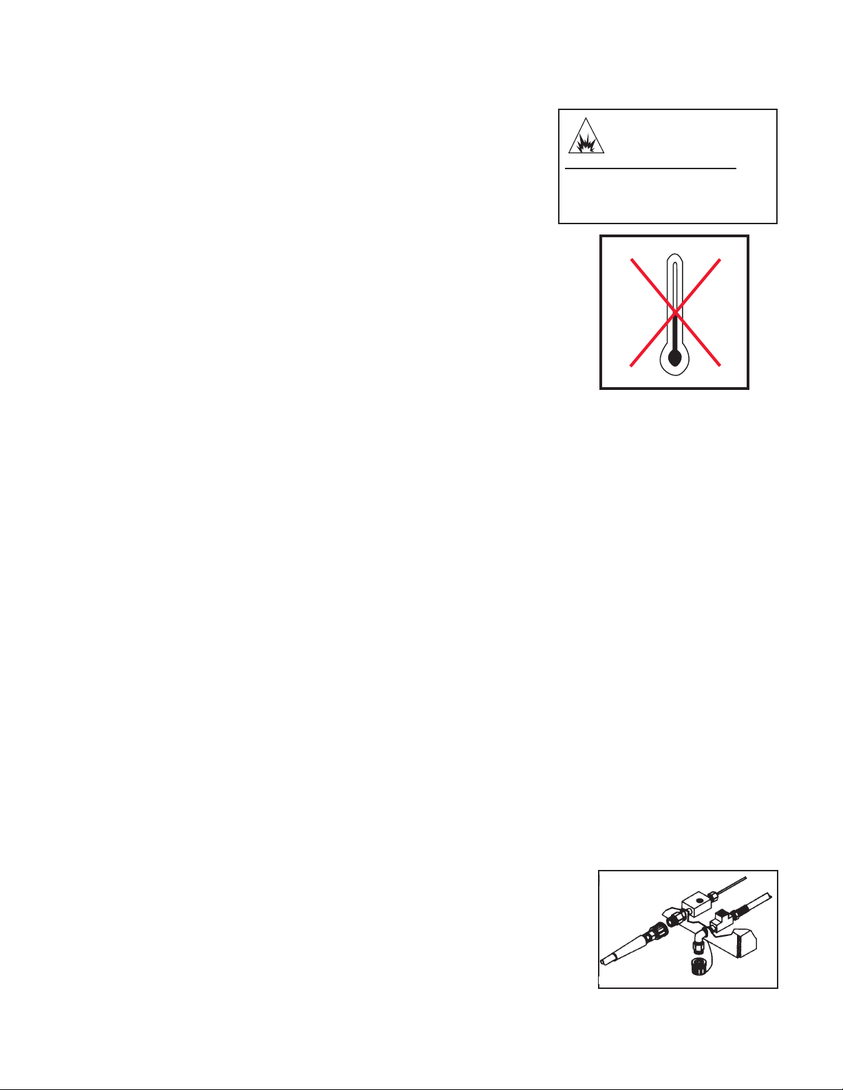
COIL DRAIN PLUG
NOTE: When using this procedure, caution should be used as ice chips can
John Deere Operator's Manual 17
form from drops of water which could cause the unit to burst if starting
before completely thawed.

TROUBLESHOOTING
SYMPTOM PROBABLE CAUSE REMEDY
Engine will not start. Various engine problems. Refer to the Engine Manual
accompanying your unit.
Unit components are frozen. Allow to thaw. If any part of the unit
becomes frozen; excessive
pressure may build up in the unit
which could cause the unit to burst
resulting in possible serious injury to
the operator or bystanders.
No discharge at nozzle when Inadequate water supply. Ensure hose is 3/4" diameter and
trigger mechanism is squeezed. incoming water supply is turned on.
Low or uctuating pressure. Kink in water inlet hose. Remove kink.
Kink in high pressure discharge hose. Replace kinked high pressure hose.
Water inlet screen obstructed. Remove screen, clean or replace.
Pump sucking air. (Prime eliminated) Tighten all water intake connections
Eliminate leaks in intake line.
Adjustable Grip on Dual Lance Turn grip counterclockwise to
is not in high pressure mode. to high pressure.
Obstructed or worn spray nozzle. Remove, clean or replace.
Damaged or obstructed valve assy. Remove, inspect, clean or replace.
on pump.
Pump packings worn. Replace packings.
Unloader/Bypass valve not operating Repair or replace.
correctly.
Water is leaking from Heat DumpValve. Water temperature is too high. Do not allow unit to operate in
bypass mode (with the trigger gun
closed) for more than three minutes.
Defective valve. Replace.
Oil appears milky or foamy. Water in oil. Change pump oil. Fill to proper
level.
Oil leaking from unit. Worn seals or o-rings. Contact Service.
Detergent will not siphon into Detergent strainer is not completely Check, submerge if necessary.
Low Pressure Detergent mode. submerged in detergent solution.
Detergent strainer obstructed. Inspect, clean or replace.
Detergent hose cut, obstructed or Inspect, clean or replace.
kinked.
Detergent adjusting knob turned to Open adjusting knob. Refer to
closed position. "Cleaning with Detergents" pg. 17.
Adjustable grip on dual lance is Turn grip clockwise to move to low
not in low pressure mode. pressure.
Nozzle assembly is plugged. Clean or replace.
Too many high pressure hose Use one extension maximum.
extensions attached to the water outlet.
Ball & Spring in Venturi stuck. Remove, clean or replace.
Water ows back into detergent Ball & Spring in Venturi reversed, Remove, clean or replace.
container. missing or corroded.
Water ows from the nozzle when the Trigger gun is malfunctioning. Repair or replace.
trigger gun is locked in the "OFF"
position.
18 John Deere Operator's Manual

TROUBLESHOOTING
SYMPTOM PROBABLE CAUSE REMEDY
Water is leaking under heat Coil drain plug is not installed. Install.
exchanger coil.
Safety relief device is relieving 1. Detect and correct unloader or
caused by an unloader or pressure p res sure s w itc h p rob lem.
switch problem. 2. Replace safety relief device.
NEVER run unit without safety
relief device. Doing so can cause
an explosion!
Burner will not ignite Burner switch is not turned on. Check switch position.
Out of fuel. Refuel.
Trigger gun is closed. Open trigger gun for pressure.
EMF Drive belt loose or broken. Adjust or replace as necessary.
Flexible coupler broken. Replace.
Dirty or clogged fuel lter/water sep. Drain or replace as necessary.
Fuel pump sucking air. Tighten all fuel intake connections.
Eliminate leaks in intake line.
Fuel pump inoperative. Check pressure, replace if needed.
Fuel pickup screen is obstructed. Consult Service.
Dirty or clogged fuel nozzle. Replace fuel nozzle.
Ignition module. Consult Service.
Ignition electrodes damaged or worn. With unit running and trigger gun
closed, look through burner sight
glass to ensure there is sparking
across electrodes.
No voltage. Consult Service.
Pressure switch override. Pressure should be over 250 PSI/
18 Bar to allow burner to come on.
High limit switch override. Allow unit to cool down before
reigniting.
Improper burner air adjustment. Adjust as shown on page 18.
Fuel solenoid valve failure. Replace.
Burner runs erratically. Water in the fuel oil. Drain fuel lter/water separator,
drain fuel tank and replace with
clean fuel.
Dirty fuel lter/water separator. Replace element.
Dirty fuel nozzle. Replace.
Improper air adjustment setting. Adjust as shown on page 18.
Fuel pickup screen is obstructed. Consult Service.
Fuel pump malfunctioning. Replace.
Burner runs, but will not heat. Poor or improper fuel supply. Check fuel to ensure it is correct.
Drain tank and lter if necessary
and rell with proper fuel.
Low fuel pump pressure. Check fuel pump pressure, replace
if needed.
Dirty fuel nozzle. Replace.
Improper air adjustment setting. Adjust as shown on page 18.
Fuel pickup screen is obstructed. Consult Service.
Scale build up in heat exchanger coil. Consult Service.
Burner discharges white smoke. Low on fuel. Refuel. If white smoke persists,
consult Service.
Excessive air supply. Adjust as shown on page 18.
Burner discharges black smoke. Insufcient air supply. Adjust as shown on page 18.
John Deere Operator's Manual 19

MAINTENANCE CHART
PROCEDURE DAILY 3 MONTHS 6 MONTHS 9 MONTHS 12 MONTHS
Check engine oil level X
Change engine oil***** X X X X
Check water pump oil level X
Change water pump oil ** X X X X
Oil leak inspection X
Fuel leak inspection X
Water leak inspection X
Hose inspection X
Water inlet lter inspection X
Check fuel lter/water separator X
Inspect belt X X X X
Replace high pressure nozzle*** X X X X
Replace fuel lter/water separator X
Inspect fuel pump lter* X
Replace fuel nozzle* X
Check burner air adjustment X X X X
Check burner electrodes* X
Test water pressure* X X X X
Test fuel pressure* X X X X
Test water temperature* X X X X
Descale coil**** X
* Must be performed by an authorized service technician.
** The pump oil must be changed after the rst 50 hours of operation and every 250 hours or 3 months, whichever
comes rst.
*** High pressure nozzle should be replaced whenever pressure is less than 85%.
**** Scale build-up will vary with mineral content in the water and amount of usage. Descaling can range from monthly
to yearly maintenance.
***** The engine oil must be changed after the rst 8 hours of operation and every 50 hours or 3 months,
whichever comes rst.
20 John Deere Operator's Manual

ACCESSORIES
PART # ACCESSORY
15-0006 SUPPLY HOSE 3/4”
50-0136 HOSE REEL 13” (HOLDS 100’ OF HOSE)
50-0137 HOSE REEL 16” (HOLDS 200’ OF HOSE)
50-0138 BRACKET FOR HOSE REEL (UNIVERSAL)
852-0138 JUMPER HOSE FOR HOSE REEL
850-0199 EXTENSION HOSE 50’
AW-3005-0035 SANDBLASTER CARBIDE NOZZLE*
AW-3010-0035 SANDBLASTER CERAMIC NOZZLE*
AW-4085-0016 PUMP OIL
AW-7004-0045 ROTATING NOZZLE*
AW-7003-1500 ROATAING BRUSH*
AW-7020-8000 ROTARY SURFACE CLEANER** (20” 4000 PSI)
AW-7020-8001 ROTARY SURFACE CLEANER** (28” 4000 PSI)
AW-7025-8000 25” POWER BROOM (5-80° NOZZLES)*/***
AW-7035-8000 35” POWER BROOM (7-80° MOZZLES)*/***
*Requires 17-0028 1/4" female quick connect.
**Requires 17-0004 3/8" female quick connect.
***PSI and GPM must be specied when ordering.
All Purpose Cleaner, Paint Surface Prep, House & Deck Wash and Heavy Duty Degreaser are specially formulated detergents for use with all HSP pressure washers and are packaged in One (1), Five (5) and Fifty-ve (55) gallon containers.
Contact Customer Service Department at (800)-553-9053 for more information.
John Deere Operator's Manual 21

STATEMENT OF WARRANTY
John Deere warrants all parts, (except those referred to below), of your new John
Deere HSP-Series Pressure Washer to be free from defects in materials and
workmanship during the following periods:
For Lifetime (Limited) against freezing and cracking:
Pump Manifold
For Seven (7) Years from the date of original purchase:
High Pressure Pump
For Three (3) Years from the date of original purchase:
Heat Exchanger Coil
For One (1) Year from the date of original purchase:
High Pressure Pump
Frame Pulley
Guard or Shields EMF System
Plumbing
For Ninety (90) days from the date of original purchase:
Control Switches Safety Switches
Regulating Valve Fuel Pump
Unloader Valve Electrodes
Fuel Solenoid Safety Relief Valve
High Limit Thermostat Temperature Switch
Pressure Switch
For Thirty (30) day from the date of original purchase:
High Pressure Hose Trigger Gun
Strainers / Filters Wand
Defective parts not subject to normal wear and tear will be repaired or replaced at our
option during the warranty period. In any event, reimbursement is limited to the purchase
price paid.
EXCLUSIONS
1. Engine is covered under separate warranty by its respective manufacturer and is
subject to the terms set forth therein.
2. Normal wear parts:
Pump Packings Spray Nozzles
Pump Valves Screw Connectors/Quick Couplings
Detergent Valves Fuel Filters
O-rings Belts
3. This warranty does not cover parts damaged due to normal wear, misapplication,
misuse, operation at other than recommended speeds, pressures or temperature.
Parts damaged or worn because of the use of caustic liquids or by operation in
abrasive or corrosive environments or under conditions causing pump cavitation
are not warranted. Failure to follow recommended operating and maintenance
procedures also voids warranty.
4. The use of other than genuine John Deere Repair Parts will void warranty. Parts
returned, prepaid to our factory or to an John Deere Authorized Service Center
will be inspected and replaced free of charge if found to be defective and subject
to warranty. There are no warranties which extend beyond the description of the
face hereof. Under no circumstances shall John Deere bear any responsibility for
loss of use of the unit, loss of time or rental, inconvenience, commercial loss or
consequential damages.
22 John Deere Operator's Manual

NOTES
John Deere Operator's Manual 23

24 John Deere Operator's Manual
 Loading...