


Series 400
6076
Diesel Engines
Serial Number
(500000- )
COMPONENT TECHNICAL MANUAL pЙкбЙл=QMM=SMTS=aбЙлЙд=bеЦбеЙл=pЙкб~д kмгДЙк=ERMMMMMJ=F
`qjQO=EOQj^oVRF=====bеЦдблЬ
Deere Power Systems Group
CTM42 (24MAR95)
LITHO IN U.S.A.
ENGLISH
D C T
C T M 4 2 2 4 M A R 9 5

Introduction
FOREWORD
This manual is written for an experienced technician. Essential tools required in performing certain service work are identified in this manual and are recommended for use.
Live with safety: Read the safety messages in the introduction of this manual and the cautions presented throughout the text of the manual.
N This is the safety-alert symbol. When you see this symbol on the machine or in this manual, be alert to the potential for personal injury.
Use this component technical manual in conjunction with the machine technical manual. An application listing in the introduction identifies product-model/component type-model relationship. See the machine technical manual for information on component removal and installation, and gaining access to the components.
This manual is divided in two parts: repair and operation and tests. Repair sections contain
necessary instructions to repair the component. Operation and tests sections help you identify the majority of routine failures quickly.
Information is organized in groups for the various components requiring service instruction. At the beginning of each group are summary listings of all applicable essential tools, service equipment and tools, other materials needed to do the job, service parts kits, specifications, wear tolerances, and torque values.
Component Technical Manuals are concise service guides for specific components. Component technical manuals are written as stand-alone manuals covering multiple machine applications.
Fundamental service information is available from other sources covering basic theory of operation, fundamentals of troubleshooting, general maintenance, and basic type of failures and their causes.
|
DX,CTMIFC -19-22MAY92 |
CTM42 (24MAR95) |
6076 Diesel Engines—S.N. (500000— ) |
|
160101 |
PN=3


Dealer Presentation Sheet
JOHN DEERE DEALERS
IMPORTANT: The changes listed below make your current CTM obsolete. Discard CTM42, dated 02 NOV 92. Please copy this page and route through your service department.
•Engine application charts updated to include the latest product models. See ENGINE APPLICATION CHART in Group 01.
•Engine coolant information revised. See ENGINE COOLANT RECOMMENDATIONS in Group 02.
•Recommendation to use ONLY JDG23 Lifting Sling and Deere provided lifting straps for lifting engines. Also recommend the use of SAE Grade 8 or higher grade cap screws and Loctite 242 when installing engine lifting straps added to Group 03.
•New “TORQUE-TO-YIELD” instructions for tightening cylinder head cap screws marked “SPECIAL” added to Group 05.
•Valve lift specifications revised in Group 05 and Group 16.
•Piston ring end gap specifications for new pistons have been added to Group 10.
•A revised (longer) JDG681A Tap for cleaning deeper tapped cylinder head cap screw holes in block added to Group 10.
•Use of JDG796 Alignment Tool for installing crankshaft rear oil seal housing added to Group 15.
•Detailed instructions for inspection of the vibration damper and the crankshaft dowel pin added to Group 15.
•Timing gear cover and rear oil seal housing replacement procedures for 6076HRW33, 34, and 35 Engines (equipped with structural front frame/oil sump), with engine installed in vehicle added to Group 15.
•Camshaft lobe lift specifications and valve lift specifications revised in Group 16.
•Recommendation against disassembly of the engine oil pump added to Group 20.
•Instructions for installation of structural front frame/oil sump on engines used in 8000 series tractors added to Group 20.
•Information and specifications for fan drive assembly with press-fit fan spacer added to Group 25.
•Torque specifications for turbocharger oil inlet line added to Group 30.
•Information to help identify A-Series and P-Series fuel injection pumps and fuel supply pumps added to Group 35.
•Instructions for disassembly and assembly of the fuel check valve deleted from Group 35. The check valve has been replaced by a non-serviceable assembly.
•In Group 100 — Engine Tune-Up and Break-In, the paragraph titled ALTITUDE COMPENSATION GUIDELINE changed to EFFECTS OF TEMPERATURE AND ALTITUDE ON ENGINE PERFORMANCE.
•In Group 105, the recommended temperatures and engine speeds for checking engine oil pressure revised. The procedure to pressure test the cooling system and radiator cap also revised.
•Dynamic timing procedure using TIME TRAC® timing kit to accurately check and adjust (rotary) injection pump-to-engine timing added to Group 115.
•Instructions and specifications for check and adjustment of the fuel shut-off solenoid added to Group 115.
•Instructions for changing 6076 generator set engines with mechanical governor from rated speed of 1800 RPM (60 Hz) to 1500 RPM (50 Hz) added to Group 115.
TIME TRAC® is a registered trademark of Stanadyne Automotive Corp. |
RG,CTM42,DPS -19-21MAR95 |
|
CTM42 (24MAR95) |
6076 Diesel Engines—S.N. (500000— ) |
|
160101 |
PN=4

ABOUT THIS MANUAL
This component technical manual covers the recommended repair procedure for 6076, 7.6 L (466 cu. in.) diesel engines produced in Waterloo, Iowa beginning with Engine Serial No. (500000— ).
Before beginning repair of an engine, clean the engine and mount on a repair stand. (See Group 03 - Engine Mounting.)
Direction of engine crankshaft rotation in this manual is referenced facing the flywheel looking toward the fan. Front of engine is fan drive end.
Some components of this engine may be serviced without removing the engine from the machine. Refer to the specific machine technical manuals for information on components that can be serviced without removing the engine from the machine and for engine removal and installation procedures.
Read each module completely before performing any service.
|
RG,CTM42,G0,1 -19-14FEB95 |
CTM42 (24MAR95) |
6076 Diesel Engines—S.N. (500000— ) |
|
160101 |
PN=5

Contents
|
Page |
Group 00—Safety |
|
Safety . . . . . . . . . . . . . . . . . . . . . . |
. . . . . 00-1 |
Group 01—General Information |
|
Unified Inch Bolt and Cap Screw Torque |
|
Values . . . . . . . . . . . . . . . . . . . . |
. . . . . 01-1 |
Metric Bolt and Cap Screw Torque |
|
Values . . . . . . . . . . . . . . . . . . . . |
. . . . . 01-2 |
Engine Model Designation . . . . . . . . . |
. . . . . 01-3 |
Engine Serial Number Plate Information |
. . . . . 01-4 |
Engine Application Chart . . . . . . . . . . . |
. . . . 01-5 |
Engine Application Chart . . . . . . . . . . . |
. . . . 01-6 |
Group 02—Fuels, Lubricants, and Coolant |
|
Diesel Fuel . . . . . . . . . . . . . . . . . . . . |
. . . . 02-1 |
Lubricity of Diesel Fuels . . . . . . . . . . . |
. . . . 02-1 |
Engine Break-In Oil . . . . . . . . . . . . . . |
. . . . 02-2 |
Engine Oil . . . . . . . . . . . . . . . . . . . . |
. . . . 02-3 |
Oilscan and Coolscan . . . . . . . . . . . . . |
. . . . 02-4 |
Grease . . . . . . . . . . . . . . . . . . . . . . . |
. . . . 02-4 |
Alternative and Synthetic Lubricants . . . |
. . . . 02-5 |
Engine Coolant Requirements . . . . . . . |
. . . . 02-5 |
Recommended Engine Coolant . . . . . . . |
. . . . 02-7 |
Engine Coolant Specifications . . . . . . . |
. . . . 02-8 |
Replenish Supplemental Coolant |
|
Additives Between Coolant Changes |
. . . . 02-10 |
Operating in Tropical Conditions . . . . . . |
. . . 02-11 |
Flush and Service Cooling System . . . . |
. . . 02-12 |
Disposing of Coolant . . . . . . . . . . . . . |
. . . 02-13 |
Group 03—Engine Mounting |
|
Engine Repair Stand . . . . . . . . . . . . . |
. . . . 03-1 |
Safety Precautions . . . . . . . . . . . . . . . |
. . . . 03-2 |
Install 400 Series Adapters on Repair |
|
Stand . . . . . . . . . . . . . . . . . . . . . . |
. . . . 03-2 |
Engine Lifting Procedure . . . . . . . . . . . |
. . . . 03-3 |
Clean Engine . . . . . . . . . . . . . . . . . . |
. . . . 03-4 |
Disconnect Turbocharger Oil Inlet Line |
. . . . . 03-4 |
Mount Engine On Repair Stand . . . . . . |
. . . . 03-5 |
|
Page |
|
||
|
|
|
|
|
|
|
|
00 |
|
Group 04—Engine Rebuild Guide |
|
|
|
|
|
|
|
||
6076 Engine Disassembly Sequence . . |
. . . . . 04-1 |
|
|
|
01 |
||||
Sealant Application Guidelines . . . . . . |
. . . . . 04-2 |
|
||
6076 Engine Assembly Sequence . . . . . |
. . . . 04-4 |
|
|
|
Group 05—Cylinder Head and Valves |
|
|
|
|
|
|
02 |
||
Special or Essential Tools |
05-1 |
|
||
|
|
|||
Service Equipment and Tools |
05-3 |
|
|
|
|
|
|||
Other Material . . . . . . . . . . . . . . . . . . |
. . . . 05-4 |
|
|
|
Cylinder Head and Valves Specifications |
. . . . 05-5 |
|
03 |
|
. . . .Check and Adjust Valve Clearance |
. . . . 05-7 |
|
|
|
. . . . . . . . . . . . . . . .Check Valve Lift |
. . . . 05-9 |
|
|
|
Remove Cylinder Head . . . . . . . . . . . . |
. . . 05-10 |
|
|
|
04 |
||||
Disassemble and Inspect Rocker Arm |
|
|
||
|
|
|
||
Shaft Assembly . . . . . . . . . . . . . . . |
. . . 05-12 |
|
|
|
|
|
|||
Assemble Rocker Arm Shaft Assembly |
. . . . 05-14 |
|
|
|
Measure Valve Recess |
05-14 |
|
|
|
05 |
||||
Preliminary Cylinder Head and Valve |
|
|
||
|
|
|
||
Checks |
05-15 |
|
|
|
|
|
|||
Remove Valve Assembly . . . . . . . . . . . |
. . . 05-16 |
|
|
|
. . .Inspect and Measure Valve Springs |
. . . 05-17 |
|
10 |
|
Inspect Valve Rotators and Wear Caps |
. . . . 05-17 |
|
|
|
. . . . . . . . . . . . . . . . . . .Clean Valves |
. . . 05-18 |
|
|
|
Inspect and Measure Valves . . . . . . . . |
. . . 05-18 |
|
|
|
15 |
||||
Grind Valves . . . . . . . . . . . . . . . . . . . |
. . . 05-19 |
|
||
|
|
|||
Inspect and Clean Cylinder Head . . . . . |
. . . 05-19 |
|
|
|
|
|
|||
Check Cylinder Head Combustion Face |
|
|
|
|
Flatness |
05-20 |
|
|
|
16 |
||||
Measure Cylinder Head Thickness |
05-21 |
|
||
|
|
|||
Clean Valve Guides |
05-22 |
|
|
|
|
|
|||
Measure Valve Guides . . . . . . . . . . . . |
. . . 05-22 |
|
|
|
. . . . . . . . . . . . . .Knurl Valve Guides |
. . . 05-23 |
|
20 |
|
. . . . . .Clean and Inspect Valve Seats |
. . . 05-23 |
|
|
|
. . . . . . . . . . . . .Measure Valve Seats |
. . . 05-24 |
|
|
|
Grind Valve Seats . . . . . . . . . . . . . . . |
. . . 05-25 |
|
|
|
25 |
||||
Remove Valve Seat Inserts and Measure |
|
|||
|
|
|||
Bores . . . . . . . . . . . . . . . . . . . . . . |
. . . 05-26 |
|
|
|
|
|
|||
Install Valve Seat Inserts . . . . . . . . . . . |
. . . 05-27 |
|
|
|
|
|
|
|
|
|
|
|
30 |
|
Continued on next page |
|
|
||
|
|
|||
All information, illustrations and specifications in this manual are based on |
35 |
||
the latest information available at the time of publication. The right is |
|
|
|
reserved to make changes at any time without notice. |
|
|
|
CTM42-19-24MAR95 |
|
||
100 |
|||
|
|
||
COPYRIGHT© 1995 |
|
|
|
DEERE & COMPANY |
|
|
|
Moline, Illinois |
|
||
All rights reserved |
|
||
105 |
|||
A John Deere ILLUSTRUCTION™ Manual |
|||
Previous Editions |
|
||
|
|
||
Copyright 1992, 1991 Deere & Company |
|
|
|
CTM42 (24MAR95) |
i |
6076 Diesel Engines—S.N. (500000— )
160101
PN=438

Contents
|
|
Page |
|
|
|
|
|
00 |
Inspect and Clean Cylinder Head Nozzle |
|
|
|
|
||
|
. . . . . . . . . . . . . . . . . . . . . . . . . .Bore |
05-27 |
|
|
Clean and Inspect Push Rods |
05-28 |
|
01 |
|||
Inspect and Clean Ventilator Outlet Hose . . . |
05-28 |
||
|
|||
|
Clean and Inspect Top Deck of Cylinder |
|
|
|
|
||
|
Block . . . . . . . . . . . . . . . . . . . . . . . . . |
05-29 |
|
02 |
Measure Cylinder Liner Standout (Height |
|
|
|
. . . . . . . . . . . . . . . . . . . .above Block) |
05-30 |
|
|
. . . . . . . . . . . . .Assemble Valve Assembly |
05-31 |
|
|
Install Cylinder Head . . . . . . . . . . . . . . . . |
05-32 |
|
03 |
|||
Cylinder Head Cap Screw Types . . . . . . . . |
05-33 |
||
|
|||
|
Clean, Inspect and Install Cylinder Head |
|
|
|
|
||
|
Cap Screws . . . . . . . . . . . . . . . . . . . . . |
05-34 |
|
|
Torque-To-Yield Special Flanged-Head |
|
|
04 |
|
||
|
. . . . . . . . . . . . . . . . . . . . .Cap Screws |
05-36 |
|
|
. . . . . . . . . . .Install Rocker Arm Assembly |
05-37 |
|
|
Complete Final Assembly Of Injection |
|
|
05 |
|
||
Pump Side . . . . . . . . . . . . . . . . . . . . . . |
05-38 |
||
|
Complete Final Assembly On Exhaust |
|
|
|
. . . . . . . . . . . . . . . . . . . .Manifold Side |
05-39 |
|
|
Perform Engine Break-In |
05-42 |
|
10 |
|||
|
Group 10—Cylinder Block, Liners, Pistons and |
||
|
|||
|
Rods |
|
|
15 |
|
||
Special or Essential Tools . . . . . . . . . . . . . |
. 10-1 |
||
|
|||
|
Service Equipment and Tools . . . . . . . . . . . |
. 10-3 |
|
|
. . . . . . . . . . . . . . . . . . . . . .Other Material |
10-3 |
|
|
Cylinder Block, Liners, Pistons, and Rods |
|
|
16 |
|
||
|
. . . . . . . . . . . . . . . . . . . . .Specifications |
10-4 |
|
|
Preliminary Liner, Piston, and Rod |
|
|
|
Checks . . . . . . . . . . . . . . . . . . . . . . . . . |
10-8 |
|
20 |
Remove Pistons and Connecting Rods . . . . . 10-9 |
||
|
Measure Cylinder Liner Standout (Height |
|
|
|
. . . . . . . . . . . . . . . . . . . .above Block) |
10-12 |
|
|
Remove Cylinder Liners |
10-13 |
|
25 |
|||
Deglazing Cylinder Liners |
10-14 |
||
|
|||
|
Clean Cylinder Liners |
10-15 |
|
|
|||
|
Disassemble and Clean Piston . . . . . . . . . . |
10-15 |
|
30 |
Visually Inspect Pistons . . . . . . . . . . . . . . . |
10-16 |
|
|
. . . . . . . .Check Piston Ring Groove Wear |
10-17 |
|
|
. . . . . . . .Measure Oil Control Ring Groove |
10-18 |
|
|
Install Piston Pin in Piston Pin Bore |
10-18 |
|
35 |
|||
Visually Inspect Cylinder Liners |
10-19 |
||
|
|||
|
Cylinder Liner Manufacturing Date Code |
|
|
|
|
||
|
Explanation . . . . . . . . . . . . . . . . . . . . . |
10-20 |
|
100 |
. . . . . . . . . . . . . .Measure Piston Skirt OD |
10-21 |
|
|
. . . . . . . . . . . . .Measure Cylinder Liner ID |
10-22 |
|
|
. . . . . . . .Measure Liner Flange Thickness |
10-22 |
|
|
Inspect and Measure Connecting Rod |
|
|
105 |
|
||
Bearings . . . . . . . . . . . . . . . . . . . . . . . |
10-23 |
||
|
|||
|
Inspect Rod and Cap . . . . . . . . . . . . . . . . |
10-24 |
|
|
|||
|
|
|
|
|
Page |
Inspect Piston Pins and Bushings . . . . . . . . |
10-26 |
Remove Piston Pin Bushing . . . . . . . . . . . . |
10-27 |
Clean and Inspect Piston Pin Bushing |
|
Bore in Rod . . . . . . . . . . . . . . . . . . . . . |
10-27 |
Install Piston Pin Bushing in Connecting |
|
Rod . . . . . . . . . . . . . . . . . . . . . . . . . . |
10-28 |
Complete Disassembly of Cylinder Block |
|
(If Required) . . . . . . . . . . . . . . . . . . . . . |
10-29 |
Remove and Clean Piston Cooling |
|
Orifices . . . . . . . . . . . . . . . . . . . . . . . . |
10-29 |
Inspect and Clean Cylinder Block . . . . . . . . |
10-30 |
Clean O-Ring Bore . . . . . . . . . . . . . . . . . . |
10-32 |
Measure Cylinder Block . . . . . . . . . . . . . . |
10-32 |
Install Piston Cooling Orifices and Gallery |
|
Plugs . . . . . . . . . . . . . . . . . . . . . . . . . |
10-34 |
Recheck Cylinder Liner Standout (Height |
|
above Block) . . . . . . . . . . . . . . . . . . . . |
10-35 |
Install Liner Shims—If Required . . . . . . . . . |
10-36 |
Install Cylinder Liner O-Rings and |
|
Packings . . . . . . . . . . . . . . . . . . . . . . . |
10-37 |
Install Cylinder Liners . . . . . . . . . . . . . . . . |
10-38 |
Install Pistons and Connecting Rods . . . . . . |
10-40 |
Torque-Turn Connecting Rod Cap Screws. . . |
10-43 |
Check Engine Rotation for Excessive |
|
Tightness . . . . . . . . . . . . . . . . . . . . . . . |
10-43 |
Complete Final Assembly . . . . . . . . . . . . . |
10-44 |
Group 15—Crankshaft, Main Bearings and |
|
Flywheel |
|
Special or Essential Tools . . . . . . . . . . . . . |
. 15-1 |
Service Equipment and Tools . . . . . . . . . . . |
. 15-4 |
Other Material . . . . . . . . . . . . . . . . . . . . . . |
15-5 |
Crankshaft, Main Bearings, and Flywheel |
|
Specifications . . . . . . . . . . . . . . . . . . . . . |
15-6 |
Failure Analysis . . . . . . . . . . . . . . . . . . . . . |
15-8 |
Remove Crankshaft Rear Oil Seal |
|
Housing |
|
(With Oil Seal Housing Installed) . . . . . . . . |
15-9 |
Install Crankshaft Rear Oil Seal and |
|
Wear Sleeve |
|
(Without Engine Disassembly) . . . . . . . . . |
15-11 |
Inspect Vibration Damper . . . . . . . . . . . . . |
15-12 |
Check Crankshaft End Play . . . . . . . . . . . . |
15-13 |
Remove Damper Pulley . . . . . . . . . . . . . . |
15-14 |
Remove Front Oil Seal |
|
(With Timing Gear Cover Installed on |
|
Engine) . . . . . . . . . . . . . . . . . . . . . . |
15-16 |
Continued on next page
CTM42 (24MAR95) |
ii |
6076 Diesel Engines—S.N. (500000— )
160101
PN=439

Contents
Page |
Page |
Remove Front Wear Sleeve |
|
(With Timing Gear Cover Installed or |
|
Removed) . . . . . . . . . . . . . . . . . . . . . |
15-17 |
Install Front Wear Sleeve |
|
(With Timing Gear Cover Installed) . . . . . |
15-17 |
Install Front Oil Seal |
|
(With Timing Gear Cover Installed) . . . . . |
15-18 |
Replace Timing Gear Cover |
|
(6076HRW33, 34, and 35 Engines) |
|
—Engine Installed in Vehicle . . . . . . . . . . |
15-19 |
Remove Timing Gear Cover . . . . . . . . . . . |
15-20 |
Inspect, Measure and Repair Flywheel . . . . |
15-20 |
Check Flywheel Housing Face Run-Out . . . . 15-21 |
|
Check Flywheel Face Flatness . . . . . . . . . . |
15-21 |
Check Pilot Bearing Bore Concentricity . . . . |
15-22 |
Remove Flywheel . . . . . . . . . . . . . . . . . . |
15-22 |
Remove SAE 1 and SAE 2 Flywheel |
|
Housing . . . . . . . . . . . . . . . . . . . . . . . . |
15-23 |
Remove SAE 3 Flywheel Housing . . . . . . . . |
15-23 |
Replace Flywheel Ring Gear . . . . . . . . . . . |
15-24 |
Replace Rear Oil Seal Housing |
|
(6076HRW33, 34, and 35 Engines) |
|
—Engines Installed in Vehicle . . . . . . . . . |
15-25 |
Remove Rear Oil Seal Housing and |
|
Wear Sleeve |
|
(With Engine Disassembled) . . . . . . . . . . |
15-26 |
Remove Crankshaft Main Bearings . . . . . . . |
15-27 |
Check Main Bearing Clearance . . . . . . . . . |
15-28 |
Remove Crankshaft . . . . . . . . . . . . . . . . . |
15-29 |
Inspect Crankshaft . . . . . . . . . . . . . . . . . . |
15-30 |
Measure Assembled ID of Bearings And |
|
OD Of Crankshaft Journals . . . . . . . . . . . |
15-32 |
Main Bearing Cap Line Bore |
|
Specifications . . . . . . . . . . . . . . . . . . . . |
15-33 |
Crankshaft Grinding Guidelines . . . . . . . . . . |
15-34 |
Thrust Bearing New Part Specifications . . . . |
15-36 |
Crankshaft Grinding Specifications . . . . . . . |
15-37 |
Replace Crankshaft Oil Pump Drive Gear . . . |
15-38 |
Replace Crankshaft Gear . . . . . . . . . . . . . |
15-39 |
Inspect Thrust Bearings . . . . . . . . . . . . . . |
15-40 |
Remove and Clean Piston Cooling |
|
Orifices . . . . . . . . . . . . . . . . . . . . . . . . |
15-40 |
Install Main Bearings and Crankshaft . . . . . . |
15-41 |
Install Crankshaft Rear Oil Seal Housing . . . |
15-43 |
Check Oil Seal Housing Runout . . . . . . . . . |
15-45 |
Crankshaft Rear Oil Seal And Wear |
|
Sleeve Handling Precautions . . . . . . . . . . |
15-46 |
Install Crankshaft Rear Oil Seal and |
|
Wear Sleeve Assembly . . . . . . . . . . . . . |
15-47 |
Install Timing Gear Cover . . . . . . . . . . . . . |
15-48 |
. . . . . . . . . . . . .Install Front Wear Sleeve |
15-48 |
|
110 |
|
Install Front Oil Seal |
|
|
|
|
(With Timing Gear Cover Installed) . . . . . |
15-49 |
|
|
|
Install Damper Pulley Assembly |
15-49 |
|
|
|
115 |
||||
Install SAE 3 Flywheel Housing |
15-50 |
|
||
|
|
|||
Install Flywheel . . . . . . . . . . . . . . . . . . . . |
15-51 |
|
|
|
|
|
|||
Install SAE 1 and SAE 2 Flywheel |
|
|
|
|
. . . . . . . . . . . . . . . . . . . . . . . .Housing |
15-51 |
|
199 |
|
. . . . . . . . . . . . .Complete Final Assembly |
15-52 |
|
|
|
Group 16—Camshaft and Timing Gear Train |
|
|
|
|
|
|
INDX |
||
Special or Essential Tools . . . . . . . . . . . . . . |
16-1 |
|
||
|
|
|||
Service Equipment and Tools . . . . . . . . . . . . |
16-3 |
|
|
|
|
|
|||
Other Material . . . . . . . . . . . . . . . . . . . . . . |
16-3 |
|
|
|
Camshaft and Timing Gear Train |
|
|
|
|
Specifications . . . . . . . . . . . . . . . . . . . . . |
16-4 |
|
|
|
Check Valve Lift . . . . . . . . . . . . . . . . . . . . |
16-6 |
|
|
|
Check Camshaft End Play . . . . . . . . . . . . . . |
16-7 |
|
|
|
Remove Damper Pulley and Timing Gear |
|
|
|
|
Cover . . . . . . . . . . . . . . . . . . . . . . . . . . |
16-7 |
|
|
|
Measure Camshaft Drive |
|
|
|
|
Gear-to-Crankshaft Gear Backlash . . . . . . . |
16-8 |
|
|
|
Remove Camshaft . . . . . . . . . . . . . . . . . . . |
16-9 |
|
|
|
Remove Camshaft Gears . . . . . . . . . . . . . |
16-11 |
|
|
|
Measure Thrust Washer Thickness . . . . . . . |
16-11 |
|
|
|
Inspect and Measure Camshaft Followers . . . |
16-12 |
|
|
|
Visually Inspect Camshaft . . . . . . . . . . . . . |
16-12 |
|
|
|
Measure Camshaft Journal OD and |
|
|
|
|
Bushing ID . . . . . . . . . . . . . . . . . . . . . . |
16-13 |
|
|
|
Measure Camshaft Lobe Lift . . . . . . . . . . . |
16-13 |
|
|
|
Install Camshaft Gears . . . . . . . . . . . . . . . |
16-14 |
|
|
|
Service Camshaft Bushings using |
|
|
|
|
JDG602 Adapter Set . . . . . . . . . . . . . . . |
16-15 |
|
|
|
Service Camshaft Bushings using |
|
|
|
|
JDG606 Adapter Set . . . . . . . . . . . . . . . |
16-17 |
|
|
|
Install Camshaft . . . . . . . . . . . . . . . . . . . . |
16-18 |
|
|
|
Install Thrust Washer and Timing Gear |
|
|
|
|
Cover . . . . . . . . . . . . . . . . . . . . . . . . . |
16-20 |
|
|
|
Install Front Oil Seal |
|
|
|
|
(With Timing Gear Cover Installed) . . . . . |
16-21 |
|
|
|
Complete Final Assembly . . . . . . . . . . . . . |
16-22 |
|
|
|
Group 20—Lubrication System |
|
|
|
|
Other Material . . . . . . . . . . . . . . . . . . . . . . |
20-1 |
|
|
|
Lubrication System Specifications . . . . . . . . . |
20-1 |
|
|
|
Drain Engine Oil and Remove Oil Pan . . . . . . |
20-2 |
|
|
|
Oil Filter and Oil Conditioning Housing |
|
|
|
|
Assembly . . . . . . . . . . . . . . . . . . . . . . . . |
20-3 |
|
|
Continued on next page
CTM42 (24MAR95) |
iii |
6076 Diesel Engines—S.N. (500000— )
160101
PN=440

Contents
|
|
|
Page |
|
|
|
Remove Oil Filter and Oil Conditioning |
|
|
110 |
|
|||
|
Housing . . . . . . . . . . . . . . . . . . . . . . . . |
. 20-4 |
||
|
|
Inspect and Replace Oil Filter Adapter . . . . . . |
20-4 |
|
|
|
Remove, Inspect, and Install Valves from |
|
|
|
|
Oil Conditioning Housing |
20-5 |
|
115 |
||||
|
Install Oil Filter and Oil Conditioning |
|
||
|
|
|
||
|
|
Housing |
20-6 |
|
|
|
|||
|
|
Remove Engine Oil Cooler . . . . . . . . . . . . . |
20-7 |
|
199 |
|
Clean, Inspect, and Install Engine Oil |
|
|
|
|
. . . . . . . . . . . . . . . . . . . . . . . . . .Cooler |
20-8 |
|
|
|
Check Crankshaft Gear-To-Oil Pump |
|
|
|
|
Drive Gear Backlash |
20-9 |
|
INDX |
||||
|
Remove Engine Oil Pump |
20-9 |
||
|
|
|||
|
|
Inspect and Clean Oil Pump . . . . . . . . . . . |
20-10 |
|
|
|
|||
|
|
Check Drive Shaft End Play . . . . . . . . . . . |
20-11 |
|
|
|
Check Drive Shaft Side Movement . . . . . . . |
20-11 |
|
|
|
Check Pumping Gear Backlash . . . . . . . . . |
20-12 |
|
|
|
Inspect Oil Pump Drive Gear . . . . . . . . . . . |
20-12 |
|
|
|
Install Engine Oil Pump . . . . . . . . . . . . . . . |
20-13 |
|
|
|
Install Oil Pan . . . . . . . . . . . . . . . . . . . . . |
20-14 |
|
|
|
Tighten cap screws on front frame/oil |
|
|
|
|
sump . . . . . . . . . . . . . . . . . . . . . . . . . |
20-15 |
Group 25—Cooling System
Special or Essential Tools . . . . . . . . . . . . . . 25-1 Other Material . . . . . . . . . . . . . . . . . . . . . . 25-2 Cooling System Specifications . . . . . . . . . . . 25-3 Service Equipment and Tools . . . . . . . . . . . . 25-5 Replace Bearings in Standard Duty,
Adjustable Fan Drive Assembly . . . . . . . . . 25-6 Replace Bearings in Heavy Duty,
Adjustable Fan Drive Assembly . . . . . . . . . 25-8 Water Manifold Mounted Fixed Fan Drive
Assembly . . . . . . . . . . . . . . . . . . . . . . . 25-10 Replace Bearing in Injection Pump Drive
Gear Mounted Fan Drive . . . . . . . . . . . . 25-12 Inspect and Check Belt Tensioner Spring
Tension . . . . . . . . . . . . . . . . . . . . . . . . 25-13 Replace Belt Tensioner Assembly . . . . . . . . 25-14 Remove Water Pump . . . . . . . . . . . . . . . . 25-14 Disassemble Water Pump . . . . . . . . . . . . . 25-15 Inspect Water Pump Parts . . . . . . . . . . . . . 25-18 Assemble Water Pump . . . . . . . . . . . . . . . 25-19 Install Water Pump . . . . . . . . . . . . . . . . . . 25-21 Remove and Test Thermostats . . . . . . . . . . 25-22 Install Thermostats . . . . . . . . . . . . . . . . . . 25-23 Remove Water Manifold . . . . . . . . . . . . . . 25-23 Install Water Manifold . . . . . . . . . . . . . . . . 25-24 Remove Coolant Heater . . . . . . . . . . . . . . 25-24 Install Coolant Heater . . . . . . . . . . . . . . . . 25-25 Complete Final Assembly . . . . . . . . . . . . . 25-26
|
Page |
Fan Belt Tension Specifications . . . . . |
. . . . 25-26 |
Group 30—Air Intake And Exhaust System |
|
Special or Essential Tools . . . . . . . . . |
. . . . . 30-1 |
Other Material . . . . . . . . . . . . . . . . . |
. . . . . 30-2 |
Air Intake and Exhaust System |
|
Specifications . . . . . . . . . . . . . . . . . |
. . . . 30-2 |
Extending Turbocharger Life . . . . . . . . |
. . . . 30-4 |
Remove Turbocharger . . . . . . . . . . . . |
. . . . 30-6 |
Turbocharger Failure Analysis . . . . . . . |
. . . . 30-8 |
Turbocharger Seven-Step Inspection . . . |
. . . 30-10 |
Perform Radial Bearing Clearance Test |
. . . . 30-15 |
Perform Axial Bearing End Play Test . . . |
. . . 30-16 |
Repair Turbocharger . . . . . . . . . . . . . . |
. . . 30-16 |
Disassemble Turbocharger . . . . . . . . . |
. . . 30-17 |
Clean and Inspect Turbine and |
|
Compressor Housings . . . . . . . . . . . |
. . . 30-18 |
Replace Center Housing Assembly and |
|
Assemble Turbocharger . . . . . . . . . . |
. . . 30-19 |
Prelube Turbocharger . . . . . . . . . . . . . |
. . . 30-20 |
Install Turbocharger . . . . . . . . . . . . . . |
. . . 30-20 |
Remove, Inspect, and Install Intake |
|
Manifold . . . . . . . . . . . . . . . . . . . . |
. . . 30-22 |
Remove Vertically-Mounted Aftercooler |
|
and Intake Manifold . . . . . . . . . . . . . |
. . . 30-23 |
Remove and Disassemble |
|
Horizontally-Mounted Aftercooler |
|
Assembly . . . . . . . . . . . . . . . . . . . . |
. . . 30-25 |
Inspect and Repair Aftercooler . . . . . . . |
. . . 30-26 |
Inspect and Repair Intake Manifold and |
|
Cover . . . . . . . . . . . . . . . . . . . . . . |
. . . 30-26 |
Install Intake Manifold and |
|
Vertically-Mounted Aftercooler . . . . . . |
. . . 30-27 |
Assemble and Install |
|
Horizontally-Mounted Aftercooler |
|
Assembly . . . . . . . . . . . . . . . . . . . . |
. . . 30-29 |
Remove, Inspect, and Install Exhaust |
|
Manifold . . . . . . . . . . . . . . . . . . . . |
. . . 30-31 |
Group 35—Fuel System |
|
Special or Essential Tools . . . . . . . . . . |
. . . . 35-1 |
Other Material . . . . . . . . . . . . . . . . . . |
. . . . 35-4 |
Diesel Fuel System Specifications . . . . . |
. . . . 35-4 |
Relieve Fuel System Pressure . . . . . . . |
. . . . 35-6 |
Replace Rectangular Fuel Filter Element |
. . . . 35-6 |
Replace Fuel Check Valve . . . . . . . . . |
. . . . 35-7 |
Remove Round Fuel Filter Element . . . . |
. . . . 35-8 |
Identification of fuel supply and fuel |
|
injection pumps . . . . . . . . . . . . . . . |
. . . . 35-9 |
Remove Mechanical Fuel Supply Pump |
. . . . 35-10 |
Continued on next page
CTM42 (24MAR95) |
iv |
6076 Diesel Engines—S.N. (500000— )
160101
PN=441
Contents
Page |
Page |
Test Mechanical Fuel Supply Pump for |
|
Leaks . . . . . . . . . . . . . . . . . . . . . . . . . |
35-11 |
Disassemble Mechanical Fuel Supply |
|
Pump (Nippondenso) . . . . . . . . . . . . . . . |
35-12 |
Inspect and Repair Mechanical Fuel |
|
Supply Pump (Nippondenso) . . . . . . . . . . |
35-14 |
Assemble Mechanical Fuel Supply Pump |
|
(Nippondenso) . . . . . . . . . . . . . . . . . . . |
35-15 |
Disassemble Mechanical Fuel Supply |
|
Pump (Robert Bosch) . . . . . . . . . . . . . . |
35-16 |
Inspect and Repair Mechanical Fuel |
|
Supply Pump (Robert Bosch) . . . . . . . . . |
35-17 |
Assemble Mechanical Fuel Supply Pump |
|
(Robert Bosch) . . . . . . . . . . . . . . . . . . . |
35-18 |
Install Mechanical Fuel Supply Pump . . . . . |
35-18 |
Remove and Install Electric Fuel Supply |
|
Pump . . . . . . . . . . . . . . . . . . . . . . . . . |
35-19 |
Clean or Replace Electric Fuel Supply |
|
Pump Filter Screen . . . . . . . . . . . . . . . . |
35-20 |
Repair Aneroid . . . . . . . . . . . . . . . . . . . . |
35-21 |
Remove Hydraulic Aneroid Activator . . . . . . |
35-21 |
Disassemble and Clean Hydraulic |
|
Aneroid Activator Parts . . . . . . . . . . . . . |
35-22 |
Assemble and Install Hydraulic Aneroid |
|
Activator . . . . . . . . . . . . . . . . . . . . . . . |
35-22 |
Service Injection Pump Overflow Valve . . . . |
35-22 |
Remove and Install Fuel Shutoff Solenoid . . . |
35-24 |
Identification of In-Line Injection Pumps . . . . |
35-25 |
Remove In-Line Fuel Injection Pump . . . . . . |
35-26 |
Install In-Line Fuel Injection Pump . . . . . . . |
35-29 |
Remove Rotary Fuel Injection |
|
Pump—Stanadyne DB4 . . . . . . . . . . . . . |
35-33 |
Install Rotary Fuel Injection |
|
Pump—Stanadyne DB4 . . . . . . . . . . . . . |
35-34 |
Remove Fuel Injection Nozzles . . . . . . . . . |
35-37 |
Diagnose Injection Nozzle Malfunction . . . . . |
35-40 |
Test Fuel Injection Nozzles . . . . . . . . . . . . |
35-42 |
Perform Opening Pressure Test . . . . . . . . . |
35-43 |
Injection Nozzle Specifications . . . . . . . . . . |
35-44 |
Perform Nozzle Leakage Test . . . . . . . . . . |
35-45 |
Perform Chatter and Spray Pattern Test . . . |
35-46 |
Disassemble Fuel Injection Nozzle . . . . . . . |
35-47 |
Clean and Inspect Fuel Injection Nozzle |
|
Assembly . . . . . . . . . . . . . . . . . . . . . . . |
35-49 |
Perform Nozzle Slide Test . . . . . . . . . . . . . |
35-50 |
Clean Spray Orifices . . . . . . . . . . . . . . . . . |
35-50 |
Inspect Nozzle Holder . . . . . . . . . . . . . . . . |
35-51 |
Inspect Gland Nut . . . . . . . . . . . . . . . . . . |
35-53 |
Assemble Fuel Injection Nozzle . . . . . . . . . |
35-54 |
Adjust Injection Nozzles . . . . . . . . . . . . . . |
35-57 |
Inspect and Clean Cylinder Head Nozzle
Bore . . . . . . . . . . . . . . . . . . . . . . . . . . 35-58
Inspect and Clean Nozzle Seating
Surface . . . . . . . . . . . . . . . . . . . . . . . . 35-59
Install Fuel Injection Nozzles . . . . . . . . . . . 35-59
Group 100—Engine Tune-Up and Break-In
Effects of Altitude and Temperature on
Engine Performance . . . . . . . . . . . . . . . 100-1 Preliminary Engine Testing . . . . . . . . . . . . 100-2 General Tune-Up Recommendations . . . . . . 100-3 Dynamometer Test . . . . . . . . . . . . . . . . . . 100-4 Engine Break-In Guidelines . . . . . . . . . . . . 100-5 Perform Engine Break-In . . . . . . . . . . . . . . 100-6 Check Crankcase Ventilation System . . . . . . 100-7 Check Air Intake System . . . . . . . . . . . . . . 100-7 Check Exhaust System . . . . . . . . . . . . . . . 100-8 Check and Service Cooling System . . . . . . . 100-8 Check Electrical System . . . . . . . . . . . . . 100-10
Group 105—Engine System Operation and Test
Special or Essential Tools . . . . . . . . . . . . |
. 105-1 |
Engine Test Specifications . . . . . . . . . . . . . |
105-3 |
Engine—Sectional View . . . . . . . . . . . . . . |
105-4 |
General Engine Description . . . . . . . . . . . . |
105-5 |
How the Lubrication System Works . . . . . . . |
105-6 |
How the Cooling System Works . . . . . . . . |
105-10 |
Head Gasket Joint Construction and |
|
Operation . . . . . . . . . . . . . . . . . . . . . |
105-12 |
Diagnosing Head Gasket Joint Failures . . . |
105-14 |
Head Gasket Inspection and Repair |
|
Sequence **M:CTM42,G105,18 -19- . . . . |
105-17 |
Diagnosing Engine Malfunctions . . . . . . . . |
105-18 |
Test Engine Compression Pressure . . . . . . |
105-21 |
Check Engine Oil Pressure . . . . . . . . . . . |
105-22 |
Inspect Thermostat and Test Opening |
|
Temperature . . . . . . . . . . . . . . . . . . . |
105-24 |
Group 110—Air Intake System Operation and Test
Special or Essential Tools . . . . . . . . . . . . . 110-1 Air Intake and Exhaust System Test
Specifications . . . . . . . . . . . . . . . . . . . . 110-2 Diagnosing Air Intake Malfunctions . . . . . . . 110-3 How the Air Intake and Exhaust System
Works . . . . . . . . . . . . . . . . . . . . . . . . . 110-4 Air Cleaner Operation . . . . . . . . . . . . . . . . 110-4 Diagnosing Turbocharger Malfunctions . . . . . 110-6 How The Turbocharger Works . . . . . . . . . . 110-7 How The Turbocharger is Lubricated . . . . . . 110-7
Continued on next page
CTM42 (24MAR95) |
v |
6076 Diesel Engines—S.N. (500000— )
160101
PN=442

Contents
Page |
Page |
How The Aftercooler Works—6076A
Engines . . . . . . . . . . . . . . . . . . . . . . . . 110-8
Check Intake Manifold Pressure
(Turbocharger Boost) . . . . . . . . . . . . . . . 110-9
Group 115—Fuel System Operation and Test
Special or Essential Tools . . . . . . . . . . . . |
. 115-1 |
Fuel System Test Specifications . . . . . . . . |
. 115-2 |
Check and Adjust Rotary fuel pump |
|
Dynamic Timing . . . . . . . . . . . . . . . . . . |
115-2 |
Fuel System Operation—In-Line Fuel |
|
Injection Pump . . . . . . . . . . . . . . . . . . |
115-10 |
Fuel System Operation—Rotary Fuel |
|
Injection Pump . . . . . . . . . . . . . . . . . . |
115-11 |
Diagnose Fuel System Malfunctions . . . . . |
115-12 |
Mechanical Fuel Supply Pump Operation |
|
Operation . . . . . . . . . . . . . . . . . . . . . |
115-16 |
Diagnosing Mechanical Fuel Supply |
|
Pump Malfunctions . . . . . . . . . . . . . . . |
115-18 |
Test Mechanical Fuel Supply Pump for |
|
Leaks . . . . . . . . . . . . . . . . . . . . . . . . |
115-19 |
Check Mechanical Fuel Supply Pump |
|
Operation . . . . . . . . . . . . . . . . . . . . . |
115-20 |
Service Mechanical Fuel Supply Pump . . . |
115-22 |
Electric Fuel Supply Pump Operation . . . . |
115-23 |
Diagnose Electric Fuel Supply Pump |
|
Malfunction . . . . . . . . . . . . . . . . . . . . |
115-24 |
Test Electric Fuel Supply Pump Output |
|
Pressure and Flow . . . . . . . . . . . . . . . |
115-25 |
Fuel Shut-Off Solenoid Resistance Test . . . |
115-27 |
Rectangular Fuel Filter Operation . . . . . . . |
115-28 |
Round (Final) Fuel Filter Operation . . . . . . |
115-28 |
Bleed the Fuel System . . . . . . . . . . . . . . |
115-29 |
Diagnose In-Line Fuel Injection Pump |
|
Malfunctions . . . . . . . . . . . . . . . . . . . . |
115-32 |
In-Line Fuel Injection Pump Operation . . . . |
115-33 |
Check Fast Idle Speed—In-Line Fuel |
|
Injection Pump . . . . . . . . . . . . . . . . . . |
115-34 |
Check and Adjust Engine Slow Idle |
|
Speed—In-Line Fuel Injection Pump . . . . |
115-35 |
Rotary Fuel Injection Pump |
|
Operation—Stanadyne DB4 . . . . . . . . . |
115-38 |
Diagnose Rotary Fuel Injection Pump |
|
Malfunctions . . . . . . . . . . . . . . . . . . . . |
115-40 |
Check and Adjust Engine Speeds on |
|
Rotary Pump . . . . . . . . . . . . . . . . . . . |
115-41 |
How the Aneroid Works—In-Line Injection |
|
Pumps . . . . . . . . . . . . . . . . . . . . . . . |
115-42 |
Diagnose Aneroid Malfunctions . . . . . . . . . |
115-43 |
How the Hydraulic Aneroid Activator |
|
Works . . . . . . . . . . . . . . . . . . . . . . . . |
115-44 |
Diagnose Malfunctions—Hydraulic |
|
Aneroid Activator . . . . . . . . . . . . . . . . |
115-45 |
Fuel Injection Nozzles—General |
|
Information . . . . . . . . . . . . . . . . . . . . . |
115-46 |
Fuel Injection Nozzle Operation . . . . . . . . |
115-47 |
Diagnose Malfunctions—Fuel Injection |
|
Nozzle . . . . . . . . . . . . . . . . . . . . . . . |
115-48 |
Test Fuel Injection Nozzles (Engine |
|
Running) . . . . . . . . . . . . . . . . . . . . . . |
115-49 |
Fuel Drain Back Test Procedure . . . . . . . . |
115-49 |
Group 199—Dealer Fabricated Tools
How to Make Tools . . . . . . . . . . . . . . . . . 199-1 Cylinder Liner Holding Fixture . . . . . . . . . . 199-1
Index
CTM42 (24MAR95) |
vi |
6076 Diesel Engines—S.N. (500000— )
160101
PN=443
HANDLE FLUIDS SAFELY—AVOID FIRES
When you work around fuel, do not smoke or work near heaters or other fire hazards.
Store flammable fluids away from fire hazards. Do not incinerate or puncture pressurized containers.
Make sure machine is clean of trash, grease, and debris.
Do not store oily rags; they can ignite and burn spontaneously.
PREVENT BATTERY EXPLOSIONS
Keep sparks, lighted matches, and open flame away from the top of battery. Battery gas can explode.
Never check battery charge by placing a metal object across the posts. Use a volt-meter or hydrometer.
Do not charge a frozen battery; it may explode. Warm battery to 16˚C (60˚F).
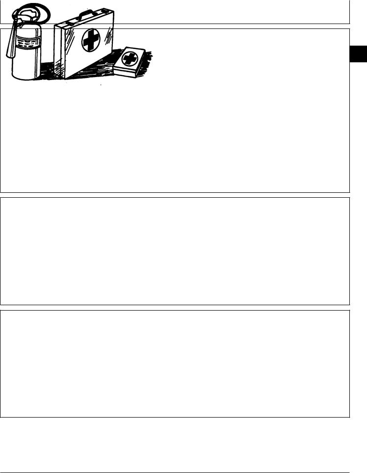
PREPARE FOR EMERGENCIES
Be prepared if a fire starts.
Keep a first aid kit and fire extinguisher handy.
Keep emergency numbers for doctors, ambulance service, hospital, and fire department near your telephone.
CTM42 (24MAR95) |
00-1 |
Group 00
Safety
00
1
TS227 -UN-23AUG88
DX,FLAME -19-04JUN90
TS204 -UN-23AUG88
DX,SPARKS -19-03MAR93
TS291 -UN-23AUG88
DX,FIRE2 -19-03MAR93
6076 Diesel Engines—S.N. (500000— )
160101
PN=6
Safety/Safety
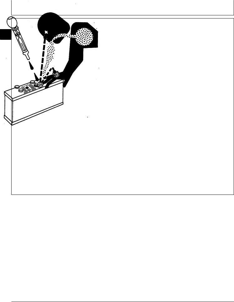
PREVENT ACID BURNS
00
2 Sulfuric acid in battery electrolyte is poisonous. It is strong enough to burn skin, eat holes in clothing, and cause blindness if splashed into eyes.
Avoid the hazard by:
1. Filling batteries in a well-ventilated area.
2. Wearing eye protection and rubber gloves.
3. Avoiding breathing fumes when electrolyte is added.
4. Avoiding spilling or dripping electrolyte.
5. Use proper jump start procedure.
If you spill acid on yourself:
1.Flush your skin with water.
2.Apply baking soda or lime to help neutralize the acid.
3.Flush your eyes with water for 15—30 minutes. Get medical attention immediately.
If acid is swallowed:
1.Do not induce vomiting.
2.Drink large amounts of water or milk, but do not exceed 2 L (2 quarts).
3.Get medical attention immediately.
TS203 -UN-23AUG88
DX,POISON -19-21APR93
CTM42 (24MAR95) |
00-2 |
6076 Diesel Engines—S.N. (500000— ) |
|
|
160101 |
PN=7

Safety/Safety
AVOID HIGH-PRESSURE FLUIDS
Escaping fluid under pressure can penetrate the skin causing serious injury.
Avoid the hazard by relieving pressure before disconnecting hydraulic or other lines. Tighten all connections before applying pressure.
Search for leaks with a piece of cardboard. Protect hands and body from high pressure fluids.
If an accident occurs, see a doctor immediately. Any fluid injected into the skin must be surgically removed within a few hours or gangrene may result. Doctors unfamiliar with this type of injury should reference a knowledgeable medical source. Such information is available from Deere & Company Medical Department in Moline, Illinois, U.S.A.
WEAR PROTECTIVE CLOTHING
Wear close fitting clothing and safety equipment appropriate to the job.
Prolonged exposure to loud noise can cause impairment or loss of hearing.
Wear a suitable hearing protective device such as earmuffs or earplugs to protect against objectionable or uncomfortable loud noises.
Operating equipment safely requires the full attention of the operator. Do not wear radio or music headphones while operating machine.
CTM42 (24MAR95) |
00-3 |
00
3
X9811 -UN-23AUG88
DX,FLUID -19-03MAR93
TS206 -UN-23AUG88
DX,WEAR -19-10SEP90
6076 Diesel Engines—S.N. (500000— )
160101
PN=8

Safety/Safety
SERVICE MACHINES SAFELY
00
4 Tie long hair behind your head. Do not wear a necktie, scarf, loose clothing, or necklace when you work near machine tools or moving parts. If these items were to get caught, severe injury could result.
Remove rings and other jewelry to prevent electrical shorts and entanglement in moving parts.
WORK IN VENTILATED AREA
Engine exhaust fumes can cause sickness or death. If it is necessary to run an engine in an enclosed area, remove the exhaust fumes from the area with an exhaust pipe extension.
If you do not have an exhaust pipe extension, open the doors and get outside air into the area.
WORK IN CLEAN AREA
Before starting a job:
•Clean work area and machine.
•Make sure you have all necessary tools to do your job.
•Have the right parts on hand.
•Read all instructions thoroughly; do not attempt shortcuts.
CTM42 (24MAR95) |
00-4 |
TS228 -UN-23AUG88
DX,LOOSE -19-04JUN90
TS220 -UN-23AUG88
DX,AIR -19-04JUN90
T6642EJ -UN-18OCT88
DX,CLEAN -19-04JUN90
6076 Diesel Engines—S.N. (500000— )
160101
PN=9

Safety/Safety
REMOVE PAINT BEFORE WELDING OR HEATING
Avoid potentially toxic fumes and dust.
Hazardous fumes can be generated when paint is heated by welding, soldering, or using a torch.
Do all work outside or in a well ventilated area. Dispose of paint and solvent properly.
Remove paint before welding or heating:
•If you sand or grind paint, avoid breathing the dust. Wear an approved respirator.
•If you use solvent or paint stripper, remove stripper with soap and water before welding. Remove solvent or paint stripper containers and other flammable material from area. Allow fumes to disperse at least 15 minutes before welding or heating.
AVOID HEATING NEAR PRESSURIZED FLUID LINES
Flammable spray can be generated by heating near pressurized fluid lines, resulting in severe burns to yourself and bystanders. Do not heat by welding, soldering, or using a torch near pressurized fluid lines or other flammable materials. Pressurized lines can be accidentally cut when heat goes beyond the immediate flame area.
ILLUMINATE WORK AREA SAFELY
Illuminate your work area adequately but safely. Use a portable safety light for working inside or under the machine. Make sure the bulb is enclosed by a wire cage. The hot filament of an accidentally broken bulb can ignite spilled fuel or oil.
CTM42 (24MAR95) |
00-5 |
00
5
TS220 -UN-23AUG88
DX,PAINT -19-03MAR93
TS953 -UN-15MAY90
DX,TORCH -19-03MAR93
TS223 -UN-23AUG88
DX,LIGHT -19-04JUN90
6076 Diesel Engines—S.N. (500000— )
160101
PN=10

Safety/Safety
USE PROPER LIFTING EQUIPMENT
00
6 Lifting heavy components incorrectly can cause severe injury or machine damage.
Follow recommended procedure for removal and installation of components in the manual.
PRACTICE SAFE MAINTENANCE
Understand service procedure before doing work. Keep area clean and dry.
Never lubricate, service, or adjust machine while it is moving. Keep hands, feet , and clothing from power-driven parts. Disengage all power and operate controls to relieve pressure. Lower equipment to the ground. Stop the engine. Remove the key. Allow machine to cool.
Securely support any machine elements that must be raised for service work.
Keep all parts in good condition and properly installed. Fix damage immediately. Replace worn or broken parts. Remove any buildup of grease, oil, or debris.
Disconnect battery ground cable (-) before making adjustments on electrical systems or welding on machine.
CTM42 (24MAR95) |
00-6 |
TS226 -UN-23AUG88
DX,LIFT -19-04JUN90
TS218 -UN-23AUG88
DX,SERV -19-03MAR93
6076 Diesel Engines—S.N. (500000— )
160101
PN=11

Safety/Safety
USE PROPER TOOLS
Use tools appropriate to the work. Makeshift tools and procedures can create safety hazards.
Use power tools only to loosen threaded parts and fasteners.
For loosening and tightening hardware, use the correct size tools. DO NOT use U.S. measurement tools on metric fasteners. Avoid bodily injury caused by slipping wrenches.
Use only service parts meeting John Deere specifications.
DISPOSE OF WASTE PROPERLY
Improperly disposing of waste can threaten the environment and ecology. Potentially harmful waste used with John Deere equipment include such items as oil, fuel, coolant, brake fluid, filters, and batteries.
Use leakproof containers when draining fluids. Do not use food or beverage containers that may mislead someone into drinking from them.
Do not pour waste onto the ground, down a drain, or into any water source.
Air conditioning refrigerants escaping into the air can damage the Earth’s atmosphere. Government regulations may require a certified air conditioning service center to recover and recycle used air conditioning refrigerants.
Inquire on the proper way to recycle or dispose of waste from your local environmental or recycling center, or from your John Deere dealer.
CTM42 (24MAR95) |
00-7 |
00
7
TS779 -UN-08NOV89
DX,REPAIR -19-04JUN90
TS1133 -UN-26NOV90
DX,DRAIN -19-03MAR93
6076 Diesel Engines—S.N. (500000— )
160101
PN=12

Safety/Safety
|
LIVE WITH SAFETY |
|
|
|
|
00 |
Before returning machine to customer, make sure |
|
8 |
|
|
|
machine is functioning properly, especially the safety |
|
|
systems. Install all guards and shields. |
|
|
|
-19-07OCT88 |
|
|
TS231 |
|
DX,LIVE |
-19-25SEP92 |
CTM42 (24MAR95) |
00-8 |
6076 Diesel Engines—S.N. (500000— ) |
|
|
160101 |
PN=13
Group 01
General Information
UNIFIED INCH BOLT AND CAP SCREW TORQUE VALUES
01
1
TS1162 -19-04MAR91
|
|
Grade 1 |
|
|
Grade 2b |
|
Grade 5, 5.1, or 5.2 |
|
Grade 8 or 8.2 |
|
||||||
|
|
|
|
|
|
|
|
|
|
|
|
|
|
|
|
|
Size |
Lubricateda |
Drya |
Lubricateda |
Drya |
Lubricateda |
Drya |
Lubricateda |
Drya |
||||||||
|
|
|
|
|
|
|
|
|
|
|
|
|
|
|
|
|
|
N·m |
lb-ft |
N·m |
lb-ft |
N·m |
lb-ft |
N·m |
lb-ft |
N·m |
lb-ft |
N·m |
lb-ft |
N·m |
lb-ft |
N·m |
lb-ft |
|
|
|
|
|
|
|
|
|
|
|
|
|
|
|
|
|
1/4 |
3.7 |
2.8 |
4.7 |
3.5 |
6 |
4.5 |
7.5 |
5.5 |
9.5 |
7 |
12 |
9 |
13.5 |
10 |
17 |
12.5 |
5/16 |
7.7 |
5.5 |
10 |
7 |
12 |
9 |
15 |
11 |
20 |
15 |
25 |
18 |
28 |
21 |
35 |
26 |
3/8 |
14 |
10 |
17 |
13 |
22 |
16 |
27 |
20 |
35 |
26 |
44 |
33 |
50 |
36 |
63 |
46 |
7/16 |
22 |
16 |
28 |
20 |
35 |
26 |
44 |
32 |
55 |
41 |
70 |
52 |
80 |
58 |
100 |
75 |
1/2 |
33 |
25 |
42 |
31 |
53 |
39 |
67 |
50 |
85 |
63 |
110 |
80 |
120 |
90 |
150 |
115 |
9/16 |
48 |
36 |
60 |
45 |
75 |
56 |
95 |
70 |
125 |
90 |
155 |
115 |
175 |
130 |
225 |
160 |
5/8 |
67 |
50 |
85 |
62 |
105 |
78 |
135 |
100 |
170 |
125 |
215 |
160 |
240 |
175 |
300 |
225 |
3/4 |
120 |
87 |
150 |
110 |
190 |
140 |
240 |
175 |
300 |
225 |
375 |
280 |
425 |
310 |
550 |
400 |
7/8 |
190 |
140 |
240 |
175 |
190 |
140 |
240 |
175 |
490 |
360 |
625 |
450 |
700 |
500 |
875 |
650 |
1 |
290 |
210 |
360 |
270 |
290 |
210 |
360 |
270 |
725 |
540 |
925 |
675 |
1050 |
750 |
1300 |
975 |
1-1/8 |
400 |
300 |
510 |
375 |
400 |
300 |
510 |
375 |
900 |
675 |
1150 |
850 |
1450 |
1075 |
1850 |
1350 |
1-1/4 |
570 |
425 |
725 |
530 |
570 |
425 |
725 |
530 |
1300 |
950 |
1650 |
1200 |
2050 |
1500 |
2600 |
1950 |
1-3/8 |
750 |
550 |
950 |
700 |
750 |
550 |
950 |
700 |
1700 |
1250 |
2150 |
1550 |
2700 |
2000 |
3400 |
2550 |
1-1/2 |
1000 |
725 |
1250 |
925 |
990 |
725 |
1250 |
930 |
2250 |
1650 |
2850 |
2100 |
3600 |
2650 |
4550 |
3350 |
DO NOT use these values if a different torque value or tightening procedure is given for a specific application. Torque values listed are for general use only. Check tightness of fasteners periodically.
Shear bolts are designed to fail under predetermined loads. Always replace shear bolts with identical grade.
a“Lubricated” means coated with a lubricant such as engine oil, or fasteners with phosphate and oil coatings. “Dry” means plain or zinc plated without any lubrication.
bGrade 2 applies for hex cap screws (not hex bolts) up to 152 mm
(6-in.) long. Grade 1 applies for hex cap screws over 152 mm (6-in.) long, and for all other types of bolts and screws of any length.
Fasteners should be replaced with the same or higher grade. If higher grade fasteners are used, these should only be tightened to the strength of the original.
Make sure fasteners threads are clean and that you properly start thread engagement. This will prevent them from failing when tightening.
Tighten plastic insert or crimped steel-type lock nuts to approximately 50 percent of the dry torque shown in the chart, applied to the nut, not to the bolt head. Tighten toothed or serrated-type lock nuts to the full torque value.
DX,TORQ1 -19-20JUL94
CTM42 (24MAR95) |
01-1 |
6076 Diesel Engines—S.N. (500000— ) |
|
|
160101 |
PN=14
General Information/Metric Bolt and Cap Screw Torque Values
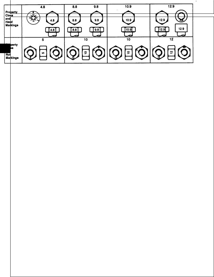
METRIC BOLT AND CAP SCREW TORQUE VALUES
01
2
TS1163 -19-04MAR91
|
|
Class 4.8 |
|
|
Class 8.8 or 9.8 |
|
|
Class 10.9 |
|
|
Class 12.9 |
|
|||||
|
|
|
|
|
|
|
|
|
|
|
|
|
|
|
|
|
|
Size |
Lubricateda |
Drya |
Lubricateda |
Drya |
Lubricateda |
Drya |
Lubricateda |
Drya |
|||||||||
|
|
|
|
|
|
|
|
|
|
|
|
|
|
|
|
|
|
|
N·m |
lb-ft |
N·m |
lb-ft |
N·m |
lb-ft |
N·m |
|
lb-ft |
N·m |
lb-ft |
N·m |
lb-ft |
N·m |
lb-ft |
N·m |
lb-ft |
|
|
|
|
|
|
|
|
|
|
|
|
|
|
|
|
|
|
M6 |
4.8 |
3.5 |
6 |
4.5 |
9 |
6.5 |
11 |
|
8.5 |
13 |
9.5 |
17 |
12 |
15 |
11.5 |
19 |
14.5 |
M8 |
12 |
8.5 |
15 |
11 |
22 |
16 |
28 |
|
20 |
32 |
24 |
40 |
30 |
37 |
28 |
47 |
35 |
M10 |
23 |
17 |
29 |
21 |
43 |
32 |
55 |
|
40 |
63 |
47 |
80 |
60 |
75 |
55 |
95 |
70 |
M12 |
40 |
29 |
50 |
37 |
75 |
55 |
95 |
|
70 |
110 |
80 |
140 |
105 |
130 |
95 |
165 |
120 |
M14 |
63 |
47 |
80 |
60 |
120 |
88 |
150 |
|
110 |
175 |
130 |
225 |
165 |
205 |
150 |
260 |
190 |
M16 |
100 |
73 |
125 |
92 |
190 |
140 |
240 |
|
175 |
275 |
200 |
350 |
255 |
320 |
240 |
400 |
300 |
M18 |
135 |
100 |
175 |
125 |
260 |
195 |
330 |
|
250 |
375 |
275 |
475 |
350 |
440 |
325 |
560 |
410 |
M20 |
190 |
140 |
240 |
180 |
375 |
275 |
475 |
|
350 |
530 |
400 |
675 |
500 |
625 |
460 |
800 |
580 |
M22 |
260 |
190 |
330 |
250 |
510 |
375 |
650 |
|
475 |
725 |
540 |
925 |
675 |
850 |
625 |
1075 |
800 |
M24 |
330 |
250 |
425 |
310 |
650 |
475 |
825 |
|
600 |
925 |
675 |
1150 |
850 |
1075 |
800 |
1350 |
1000 |
M27 |
490 |
360 |
625 |
450 |
950 |
700 |
1200 |
|
875 |
1350 |
1000 |
1700 |
1250 |
1600 |
1150 |
2000 |
1500 |
M30 |
675 |
490 |
850 |
625 |
1300 |
950 |
1650 |
|
1200 |
1850 |
1350 |
2300 |
1700 |
2150 |
1600 |
2700 |
2000 |
M33 |
900 |
675 |
1150 |
850 |
1750 |
1300 |
2200 |
|
1650 |
2500 |
1850 |
3150 |
2350 |
2900 |
2150 |
3700 |
2750 |
M36 |
1150 |
850 |
1450 |
1075 |
2250 |
1650 |
2850 |
|
2100 |
3200 |
2350 |
4050 |
3000 |
3750 |
2750 |
4750 |
3500 |
DO NOT use these values if a different torque value |
Make sure fasteners threads are clean and that you |
||||||||||||||||
or tightening procedure is given for a specific |
|
|
properly start thread engagement. This will prevent |
||||||||||||||
application. Torque values listed are for general use |
them from failing when tightening. |
|
|
|
|||||||||||||
only. Check tightness of fasteners periodically. |
|
|
|
|
|
|
|
|
|
|
|
||||||
|
|
|
|
|
|
|
|
|
Tighten plastic insert or crimped steel-type lock nuts |
||||||||
Shear bolts are designed to fail under predetermined |
to approximately 50 percent of the dry torque shown |
||||||||||||||||
loads. Always replace shear bolts with identical |
|
|
in the chart, applied to the nut, not to the bolt head. |
||||||||||||||
property class. |
|
|
|
|
|
|
|
Tighten toothed or serrated-type lock nuts to the full |
|||||||||
|
|
|
|
|
|
|
|
|
torque value. |
|
|
|
|
|
|
||
Fasteners should be replaced with the same or higher property class. If higher property class fasteners are used, these should only be tightened to the strength of the original.
a “Lubricated” means coated with a lubricant such as engine oil, or |
|
|
fasteners with phosphate and oil coatings. “Dry” means plain or zinc |
|
|
plated without any lubrication. |
DX,TORQ2 |
-19-20JUL94 |
|
CTM42 (24MAR95) |
01-2 |
6076 Diesel Engines—S.N. (500000— ) |
|
|
160101 |
PN=15

General Information/Engine Model Designation
ENGINE MODEL DESIGNATION
JOHN DEERE ENGINE MODEL—6076
John Deere engine model designation includes number of cylinders, displacement in liters, aspiration, user code, and application code. For example:
6076HH030 Engine
6 . . . . . . . . . . . . . . . . . . . . . . . . . . . . . . . . . Number of cylinders 076 . . . . . . . . . . . . . . . . . . . . . . . . . . . . . . . . Liter displacement H . . . . . . . . . . . . . . . . . . . . . . . . . . . . . . . . Aspiration code H . . . . . . . . . . . . . . . . . . . . . . . . . . . . . . . . End user code 030 . . . . . . . . . . . . . . . . . . . . . . . . . . Application code
Aspiration Code
A . . . . . . . . . . . . . . . . . Turbocharged and air-to-coolant aftercooled H . . . . . . . . . . . . . . . . . . . . Turbocharged and air-to-air aftercooled T . . . . . . . . . . . . . . . . . . . . . . . . . . . . . . . . . . . . . Turbocharged
End User Code
DW . . . . . . . . . . . . . . . . . . . . . . . . . . . . . . . . . . . . . . . Davenport
F . . . . . . . . . . . . . . . . . . . . . . . . . . . . . . . . . . . . . . . . . . . OEM
H . . . . . . . . . . . . . . . . . . . . . . . . . . . . . . . . . . . . . . . . Harvester
N . . . . . . . . . . . . . . . . . . . . . . . . . . . . . . . . . . . . . . Des Moines
RW . . . . . . . . . . . . . . . . . . . . . . . . . . . . . . . . . . . . . . . . . Tractor
T . . . . . . . . . . . . . . . . . . . . . . . . . . . . . . . . . . . . . . . . Dubuque
Z . . . . . . . . . . . . . . . . . . . . . . . . . . . . . . . . . . . . . . Zweibrucken
01
3
Application Code
30, 31, etc.
RG,CTM42,G1,1 -19-14FEB95
CTM42 (24MAR95) |
01-3 |
6076 Diesel Engines—S.N. (500000— ) |
|
|
160101 |
PN=16

General Information/Engine Serial Number Plate Information
|
ENGINE SERIAL NUMBER PLATE |
|
|
INFORMATION |
|
|
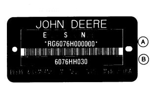
IMPORTANT: The engine serial number plate can be |
|
|
|
easily destroyed. Remove the plate or |
01 |
|
record the information elsewhere, |
4 |
|
before “hot tank” cleaning the block. |
|
||
|
• Engine Serial Number (A) |
|
|
Each engine has a 13-digit John Deere engine serial |
|
|
number identifying the producing factory, engine model |
|
|
designation, and a 6-digit sequential number. The |
|
|
following is an example: |
|
|
RG6076H000000 |
|
|
RG . . . . . . . . . |
. . . . . Factory code producing engine |
|
6076H . . . . . |
. . . . . Engine Model Designation |
000000 . |
. . . . Sequential Number |
|
Factory Code Producing Engine
RG . . . . . . . . Waterloo Engine Works
Engine Model Designation
6076H . . . . . . Definition explained previously. (See ENGINE MODEL DESIGNATION.)
Sequential Number
000000 . . . . . 6-digit sequential number.
The engine serial number plate is located either on the right-hand side of engine between the oil conditioning housing and fuel injection pump (viewed from flywheel end) or on the left-hand side of the block directly above the starting motor.
• Engine Application Data (B)
The second line of information on the engine serial number plate identifies the engine/Deere machine or OEM relationship. See ENGINE APPLICATION CHART later in this group.
CTM42 (24MAR95) |
01-4 |
 RG5804 -UN-12AUG91
RG,CTM42,G1,2 -19-14FEB95
6076 Diesel Engines—S.N. (500000— )
160101
PN=17

General Information/Engine Application Chart
ENGINE APPLICATION CHART
John Deere Agricultural Equipment Applications
Machine Model No. |
Engine Model |
COMBINES—HARVESTER WORKS
CTS Rice Combine* . . . . . . . . . . . . . . . . . . . . . . . 6076HH030 2056 . . . . . . . . . . . . . . . . . . . . . . . . . . . . . . . . . 6076AZ031 2058 . . . . . . . . . . . . . . . . . . . . . . . . . . . . . . . . . 6076AZ030 2064 . . . . . . . . . . . . . . . . . . . . . . . . . . . . . . . . . 6076AZ030 2066 . . . . . . . . . . . . . . . . . . . . . . . . . . . . . . . . . 6076HZ031
9500* . . . . . . . . . . . . . . . . . . . . . . . . . . . . . . . . 6076HH031, 6076HH032 9600* . . . . . . . . . . . . . . . . . . . . . . . . . . . . . . . . 6076HH030, 6076HH031
COMBINES—ZWEIBRUCKEN
2056 Hillmaster . . . . . . . . . . . . . . . . . . . . . . . . . . 6076AZ031
2058 Hillmaster . . . . . . . . . . . . . . . . . . . . . . . . . . 6076AZ030
2064 Hillmaster . . . . . . . . . . . . . . . . . . . . . . . . . . 6076AZ030
2066 Hillmaster . . . . . . . . . . . . . . . . . . . . . . . . . . 6076HZ031
01
5
FORAGE HARVESTERS—ZWEIBRUCKEN
6610 . . . . . . . . . . . . . . . . . . . . . . . . . . . . . . . . . 6076HZ030
COTTON PICKER—DES MOINES
9960** . . . . . . . . . . . . . . . . . . . . . . . . . . . . . . . . 6076AN030 9965 . . . . . . . . . . . . . . . . . . . . . . . . . . . . . . . . . 6067AN031
TRACTORS—WATERLOO
7700 . . . . . . . . . . . . . . . . . . . . . . . . . . . . . . . . . 6076TRW31 7800 . . . . . . . . . . . . . . . . . . . . . . . . . . . . . . . . . 6076TRW30 8100 . . . . . . . . . . . . . . . . . . . . . . . . . . . . . . . . . 6076HRW33 8200 . . . . . . . . . . . . . . . . . . . . . . . . . . . . . . . . . 6076HRW34 8300 . . . . . . . . . . . . . . . . . . . . . . . . . . . . . . . . . 6076HRW35 8560 4-Wheel Drive*** . . . . . . . . . . . . . . . . . . . . . 6076HRW30 8570 4-Wheel Drive . . . . . . . . . . . . . . . . . . . . . . . 6076HRW32
*Beginning with combine serial number (645000— )
**Above P.I.N. 4001
*** Beginning with tractor serial number (5000— ) |
RG,CTM42,G1,3 -19-16AUG94 |
|
CTM42 (24MAR95) |
01-5 |
6076 Diesel Engines—S.N. (500000— ) |
|
|
160101 |
PN=18

|
|
General Information/Engine Application Chart |
|
|
|
|
|
|
|
ENGINE APPLICATION CHART—CONTINUED |
|
|
John Deere Industrial Equipment Applications |
|
|
Machine Model No. |
Engine Model |
|
|
|
01 |
LOADERS—DUBUQUE |
|
6 |
|
|
|
. . . . . . . . . . . . . . . . . .644G |
. . . . . . . . . . . . . . . 6076ADW30 |
|
644GH . . . . . . . . . . . . . . . . . . |
. . . . . . . . . . . . . . 6076ADW32 |
|
644G Dual Power . . . . . . . . . . |
. . . . . . . . . . . . . . 6076ADW33 |
|
MOTOR GRADERS—DUBUQUE |
|
|
770B . . . . . . . . . . . . . . . . . . . |
. . . . . . . . . . . . . . 6076TDW30 |
|
770BH . . . . . . . . . . . . . . . . . . |
. . . . . . . . . . . . . . 6076ADW31 |
|
772BH . . . . . . . . . . . . . . . . . . |
. . . . . . . . . . . . . . 6076ADW31 |
|
EXCAVATORS—DUBUQUE |
|
|
892E . . . . . . . . . . . . . . . . . . . |
. . . . . . . . . . . . . . 6076AT030 |
|
BULLDOZERS—DUBUQUE |
|
|
850C . . . . . . . . . . . . . . . . . . . |
. . . . . . . . . . . . . . 6076AT032 |
|
|
RG,CTM42,G1,3B -19-16AUG94 |
|
|
|
|
OEM APPLICATIONS |
|
|
Machine Model No. |
Engine Model |
|
Marine . . . . . . . . . . . . . . . . . . |
. . . . . . . . . . . . . 6076AFM030 |
|
OEM Repower . . . . . . . . . . . . . |
. . . . . . . . . . . . . 6076AF030 |
|
|
6076HF030 |
|
|
6076TF030 |
|
|
RG,CTM42,G1,3A -19-16AUG94 |
CTM42 (24MAR95) |
01-6 |
6076 Diesel Engines—S.N. (500000— ) |
|
|
160101 |
PN=19
|
|
|
Group 02 |
|
|
|
|
Fuels, Lubricants, and Coolant |
|
|
|
|
|
|
|
|
|
|
|
|
|
|
|
DIESEL FUEL |
|
|
|
|
|
Consult your local fuel distributor for properties of the |
|
• Sulfur Content |
|
|
|
diesel fuel available in your area. |
|
— Sulfur content should not exceed 0.5%. Sulfur |
|
|
|
|
|
content less than 0.05% is preferred. |
|
|
|
In general, diesel fuels are blended to satisfy the low |
|
— If diesel fuel with sulfur content greater than 0.5% |
|
|
|
temperature requirements of the geographical area in |
|
is used, reduce the service interval for engine oil and |
|
|
|
which they are marketed. |
|
filter changes by 50%. |
|
|
|
|
|
— DO NOT use diesel fuel with sulfur content greater |
|
|
|
|
|
|
02 |
||
Diesel fuels specified to EN 590 or ASTM D975 are |
|
than 1.0%. |
|
|
|
|
|
|
1 |
||
recommended. |
|
|
|
|
|
|
Bio-diesel fuels meeting DIN 51606 or equivalent |
|
|
||
|
|
|
|
||
In all cases, the fuel must meet the following |
|
specification may be used. |
|
|
|
properties: |
|
|
|
|
|
• Cetane Number 40 minimum. Cetane number |
|
|
|
|
|
greater than 50 is preferred, especially for |
|
|
|
|
|
temperatures below -20˚ C (-4˚ F) or elevations |
|
|
|
|
|
above 1500 m (5000 ft). |
|
|
|
|
|
• Cold Filter Plugging Point (CFPP) below the |
|
|
|
|
|
expected low temperature OR Cloud Point at least |
|
|
|
|
|
5˚ C (9˚ F) below the expected low temperature. |
|
|
|
|
|
|
|
|
RG,FUEL1 -19-22FEB95 |
|
|
|
|
|
|
|
|
LUBRICITY OF DIESEL FUELS |
|
|
|
|
|
Diesel fuel must have adequate lubricity to ensure |
|
Fuel lubricity should pass a minimum of 3300 gram |
|
|
|
proper operation and durability of fuel injection system |
load level as measured by the BOCLE scuffing test. |
|
|
||
components. |
|
|
|
|
|
|
|
ASTM D975 and EN 590 specifications do not require |
|
|
|
Diesel fuels for highway use in the United States now |
fuels to pass a fuel lubricity test. Diesel fuels meeting |
|
|
||
require sulfur content less than 0.05%. Diesel fuel in |
|
U.S. Military Specification VV—F—800E pass a fuel |
|
|
|
the European Union will require sulfur content less |
|
lubricity test. |
|
|
|
than 0.05% by 1 October 1996. |
|
|
|
|
|
|
|
If fuel of low or unknown lubricity is used, add John |
|
|
|
Experience shows that some low sulfur diesel fuels |
|
Deere ALL-SEASON DIESEL FUEL CONDITIONER |
|
|
|
may have inadequate lubricity and their use may |
|
or equivalent at the specified concentration. |
|
|
|
reduce performance in fuel injection systems due to |
|
|
|
|
|
inadequate lubrication of injector components. The |
|
|
|
|
|
lower concentration of aromatic compounds in these |
|
|
|
|
|
fuels also adversely affects injection pump seals and |
|
|
|
|
|
may result in leaks. |
|
|
|
|
|
Use of low lubricity diesel fuels may also cause |
|
|
|
|
|
accelerated wear, injection nozzle erosion or |
|
|
|
|
|
corrosion, engine speed instability, hard starting, low |
|
|
|
|
|
power, and engine smoke. |
|
|
|
|
|
|
|
|
RG,FUEL5 -19-22FEB95 |
|
|
CTM42 (24MAR95) |
02-1 |
6076 Diesel Engines—S.N. (500000— |
) |
|
|
|
|
|
160101 |
|
|
PN=20

Fuels, Lubricants, and Coolant/Engine Break-In Oil
|
ENGINE BREAK-IN OIL |
|
|
|
New engines are filled at the factory with John Deere |
IMPORTANT: Do not use John Deere PLUS-50 oil |
|
|
ENGINE BREAK-IN OIL. During the break-in period, |
or engine oils meeting API CG4, |
|
|
add John Deere ENGINE BREAK-IN OIL as needed |
API CF4, or CCMC D5 performance |
|
|
to maintain the specified oil level. |
levels during the first 100 hours of |
|
|
|
operation of a new or rebuilt engine. |
|
|
Change the oil and filter after the first 100 hours of |
These oils will not allow the engine |
|
|
operation of a new or rebuilt engine. |
to break-in properly. |
|
02 |
|||
|
|
||
2 |
After engine overhaul, fill the engine with John Deere |
|
|
|
|
||
|
ENGINE BREAK-IN OIL. |
|
|
|
If John Deere ENGINE BREAK-IN OIL is not |
|
|
|
available, use a diesel engine oil meeting one of the |
|
|
|
following during the first 100 hours of operation: |
|
|
|
• API Service Classification CE |
|
|
|
• CCMC Specification D4 |
|
|
|
After the break-in period, use John Deere PLUS-50® |
|
|
|
or other diesel engine oil as recommended in this |
|
|
|
manual. |
|
|
|
|
DX,ENOIL4 -19-17OCT94 |
CTM42 (24MAR95) |
02-2 |
6076 Diesel Engines—S.N. (500000— ) |
|
|
160101 |
PN=21
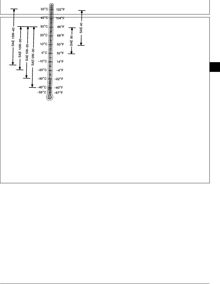
Fuels, Lubricants, and Coolant/Engine Oil
DIESEL ENGINE OIL
Use oil viscosity based on the expected air temperature range during the period between oil changes.
The following oil is preferred.
• John Deere PLUS-50®
If John Deere PLUS-50 engine oil and a John Deere oil filter are used, the service interval for oil and filter changes may be extended by 50 hours.
The following oil is also recommended:
• John Deere TORQ-GARD SUPREME®
Other oils may be used if they meet one or more of the following:
•John Deere UNI-GARD™
•API Service Classification CG-4
•API Service Classification CF-4
•API Service Classification CE
•CCMC Specification D5 and Mercedes Benz MB228.3
•CCMC Specification D4 and Mercedes Benz MB228.1
Viscosity grade SAE 15W-40 is preferred.
If diesel fuel with sulfur content greater than 0.5% is used, reduce the service interval by 50%.
02
3
TS1619 -UN-12SEP94
DX,ENOIL -19-16SEP94
CTM42 (24MAR95) |
02-3 |
6076 Diesel Engines—S.N. (500000— ) |
|
|
160101 |
PN=22
Fuels, Lubricants, and Coolant/Grease
OILSCAN® AND COOLSCAN™
OILSCAN and COOLSCAN are John Deere sampling programs to help you monitor machine performance and identify potential problems before they cause serious damage.
Oil and coolant samples should be taken from each
system prior to its recommended change interval.
02
4Check with your John Deere dealer for the availability of OILSCAN and COOLSCAN kits.
T6828AB -UN-15JUN89
T6829AB -UN-18OCT88
DX,OILSCAN -19-16APR92
GREASE
Use grease based on the expected air temperature range during the service interval.
The following greases are preferred:
•John Deere MOLY HIGH TEMPERATURE EP GREASE
•John Deere HIGH TEMPERATURE EP GREASE
•John Deere GREASE-GARD™
Other greases may be used if they meet one of the following:
•SAE Multipurpose EP Grease with a maximum of 5% molybdenum disulfide
•SAE Multipurpose EP Grease
Greases meeting Military Specification MIL-G-10924F may be used as arctic grease.
CTM42 (24MAR95) |
02-4 |
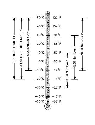 TS1622 -UN-02NOV94
DX,GREA1 -19-02NOV94
6076 Diesel Engines—S.N. (500000— )
160101
PN=23
 Loading...