


AC-G13010S AC-G14010H Generators
Operator’s Manual |
1 |

Introduction
THANK YOU for purchasing a John Deere product.
READ THIS MANUAL carefully to learn how to operate and service your machine correctly. Failure to do so could result in personal injury or equipment damage.
THIS MANUALSHOULD BE CONSIDERED a permanent part of your machine and should remain with the machine when you sell it.
MEASUREMENTS in this manual are given in both metric and customary U.S. unit equivalents. Use only correct replacement parts and fasteners. Metric and inch fasteners may require a specific metric or inch wrench.
RIGHT HAND AND LEFT HAND sides are determined by facing the motor end of the machine.
The SERIAL NUMBER is located in the Specification or Identification Numbers section. Accurately record all the numbers to help in tracing the machine should it be stolen. Your dealer also needs these numbers when you order parts. File the identification numbers in a secure place off the machine.
WARRANTY is provided from your dealer for customers who operate and maintain their equipment as described in this manual. The warranty is explained on the warranty certificate shown in this manual.
This warranty provides you the assurance that your dealer will back products where defects appear within the warranty period. Should the equipment be abused, or modified to change its performance beyond the original factory specifications, the warranty will become void.
PROTECT YOUR INVESTMENT......
Use only John Deere Fuel Protect Fuel Stabilizer with Ethanol Protection TY27534 or TY27535. Developed to ensure Optimum Performance and Protection.
IMPORTANT...Use Year Round!
34-1904 012011
Warning: This product contains lead, a chemical known to the State of California to cause birth defects or other reproductive harm.
Wash your hands after handling this product.
2 |
Operator’s Manual |

Contents
|
Page |
Safety ......................................................................... |
5 |
Safety Signs .............................................................. |
6 |
Controls .................................................................. |
13 |
Preparing the Generator ........................................ |
14 |
Operation ................................................................. |
18 |
Troubleshooting ..................................................... |
22 |
Service ..................................................................... |
23 |
Storage .................................................................... |
29 |
Specifications ......................................................... |
30 |
Warranty .............................................................. |
31-33 |
All information, illustrations and specifications in this manual are based on the latest information available at the time of publication. The right is reserved to make changes at any time without notice.
Operator’s Manual |
3 |

Contents
4 |
Operator’s Manual |
Safety
RECOGNIZE SAFETY INFORMATION
This is the safety alert symbol. When you see this symbol on your machine or in this manual, be alert to the potential for personal injury.
Follow recommended precautions and safe operating practices.
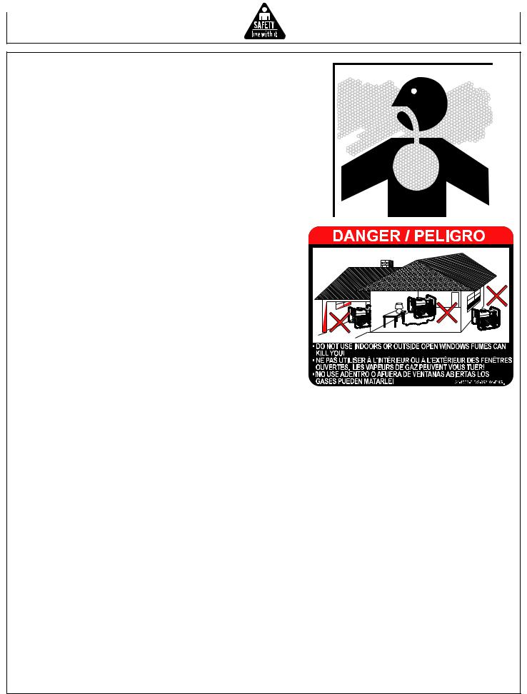
UNDERSTAND SIGNAL WORDS
Asignal word--DANGER, WARNING or CAUTION--is used with the safety-alert symbol. DANGER identifies the most serious hazards.
DANGER or WARNING safety signs are located near specific hazards. General precautions are listed on CAUTION safety signs. CAUTION also calls attention to safety messages in this manual.
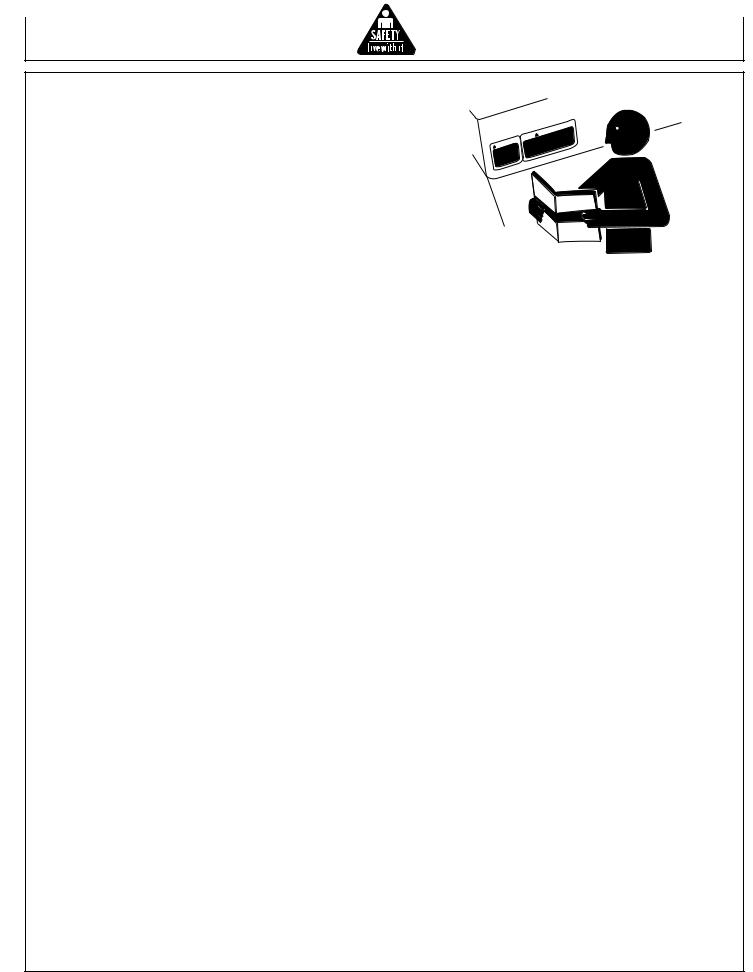
FOLLOW SAFETY INSTRUCTIONS
Carefully read all safety messages in this manual and safety signs on your machine. Keep safety signs in good condition. Replace missing or damaged safety signs. Be sure new equipment components and repair parts include the current safety signs. Replacement safety signs are available from your John Deere Customer Service Representative.
Learn how to operate the machine and how to use controls properly. Do not let anyone operate without instruction.
Keep your machine in proper working condition. Unauthorized modifications to the machine may impair the function and/or safety and affect machine life.
If you do not understand any part of this manual and need assistance, contact your John Deere Customer Service Representative.
|
|
|
|
|
G |
|
|
|
|
|
IN |
|
|
|
|
|
N |
|
|
|
|
|
R |
|
|
|
|
A |
|
|
IN |
|
||
W |
|
|
GS |
|
||
|
|
|
S. |
|||
|
|
NIN |
|
|||
AR |
|
AL |
|
|||
W |
|
|
NU |
|
|
|
HE MA |
SIN |
. |
||||
T |
|
|
ING |
|
||
|
|
RN |
|
LS |
||
|
A |
|
UA |
|
||
W |
|
AN |
|
|
||
|
|
E M |
|
|
|
|
TH |
|
|
|
|
||
|
|
|
|
|
|
|
|
N |
|
|
|
|
|
|
|
|
|
U |
IO |
ON |
|
|
|||||
|
|
|
A |
T |
|
TI |
|
SIN |
|||||
|
|
|
|
|
|
|
|
|
S |
||||
|
|
C |
|
|
|
AU |
|
|
|
AL |
|||
|
|
|
|
|
|
OC |
|
|
NU |
|
|||
|
|
|
IN |
|
|
HE |
MA |
|
SIN |
||||
|
|
NS |
|
|
|
|
|
UT |
|
|
|
LS |
|
|
TIO |
|
LS |
O |
CA |
|
|
|
UA |
||||
OCAU |
NUA |
|
|
|
EM |
|
|
|
|||||
HEMA NSIN |
OTH |
|
|
|
|
|
|||||||
OT |
|
TIO |
|
|
S |
|
|
|
|
|
|
|
|
|
U |
|
|
AL |
|
|
|
|
|
|
|
|
|
OCA |
NU |
|
|
|
|
|
|
|
|
|
|||
|
HE |
MA |
|
|
|
|
|
|
|
|
|
|
|
OT |
|
|
|
|
|
|
|
|
|
|
|
|
|
Operator’s Manual |
5 |
CARBON MONOXIDE - POISONOUS GAS
Use generator outdoors, away from open windows, vents, or doors.
Generator exhaust contains carbon monoxide - a poisonous gas that can kill you. You CAN NOT smell or see this gas.
Never use a generator in enclosed or partially-enclosed spaces. Generators can produce high levels of carbon monoxide very quickly. When you use a portable generator, remember that you cannot smell or see carbon monoxide. Even if you can’t smell exhaust fumes, you may still be exposed to carbon monoxide.
If you start to feel sick, dizzy, or weak while using a generator, get to fresh air RIGHT AWAY. DO NOT DELAY. The carbon monoxide from generators can rapidly lead to full incapacitation and death.
If you experience serious symptoms, get medical attention immediately. Inform medical staff that carbon monoxide poisoning is suspected. If you experienced symptoms while indoors, have someone call the fire department to determine when it is safe to re-enter the building.
NEVER operate the generator in an explosive atmosphere, near combustible materials or where ventilation is not sufficient to carry away exhaust fumes. Exhaust fumes can cause serious injury or death.
NEVER use a generator indoors, including in homes, garages, basements, crawl spaces, and other enclosed or partially-enclosed areas, even with ventilation. Opening doors and windows or using fans will not prevent carbon monoxide build-up in the home.
Follow the instructions that come with your generator. Locate the unit outdoors and away from doors, windows, and vents that could allow the carbon monoxide gas to come indoors.
ONLY run generator outdoors and away from air intakes.
NEVER run generator inside homes, garages, sheds, or other semi-enclosed spaces. These spaces can trap poisonous gases EVEN IF you run a fan or open doors and windows.
If you start to feel sick, dizzy, or weak while using the generator, shut if off and get fresh air RIGHT AWAY. See a doctor. You may have carbon monoxide poisoning.
Install battery-operated carbon monoxide alarms or plug-in carbon monoxide alarms with battery back-up in your home, according to the manufacturer’s installation instructions. The carbon monoxide alarms should be certified to the requirements of the latest safety standards for carbon monoxide alarms. (UL 2034, IAS 6-96, or CSA 6.19.01).
Test your carbon monoxide alarm frequently and replace dead batteries.
6 |
Operator’s Manual |

SAFETY WARNING WHEN REFUELING
Gasoline is extremely flammable and its vapors can explode if ignited.
Observe all safety regulations for the safe handling of fuel. Handle fuel in safety containers. If the container does not have a spout, use a funnel.
Do not overfill the fuel tank, leave room for the fuel to expand.
Do not refill fuel tank while the engine is running. Before refueling the generator, turn it off and let it cool down. Gasoline spilled on hot engine parts could ignite.
Fill the tank only on an area of bare ground. While fueling the tank, keep heat, sparks and open flame away. Carefully clean up any spilled fuel before starting engine.
Always fill fuel tank in an area with plenty of ventilation to avoid inhaling dangerous fumes.
NEVER store fuel for your generator in the home. Gasoline, propane, kerosene, and other flammable liquids should be stored outside of living areas in properly-labeled, non-glass safety containers. Do not store them near a fuel-burning appliance, such as a natural gas water heater in a garage. If the fuel is spilled or the container is not sealed properly, invisible vapors from the fuel can travel along the ground and can be ignited by the appliance’s pilot light or by arcs from electric switches in the appliance.
GROUND FAULT CIRCUIT INTERRUPTER PROTECTION
These generators are equipped with three GFCI (Ground Fault Circuit Interrupters) 120V duplex receptacles for protection against the hazards of electrical shock from defective attachments such as, tools, cords, and cables.
WARNING: The GFCIs may not function unless the generator is properly grounded. Follow the correct procedure specified in the section labeled “GROUNDING
INSTRUCTIONS”
A GFCI is a device that interrupts electricity from either the utility or generator by means of a special type of circuit breaker if a fault current flow to the ground occurs.
WARNING: Only the 120V Duplex Receptacles are protected by the GFCI.
A GFCI can be used only with generators that have the neutral wire internally bonded to the frame, and the frame properly grounded to the earth. A GFCI will not work on generators that do not have the neutral wire bonded to the frame, or on generators which have not been properly grounded. All John Deere generators have internally bonded ground wires. A GFCI will not work if the unit is not properly grounded.
AGFCI may be required by OSHAregulations, the National Electric Code and/or local and federal codes when operating a generator.
For additional protections against shock hazards due to defective equipment attached to the twist-lock receptacles, consider the use of a GFCI on each of these receptacles as well.
GFCIs and GFCI protected cord sets and cables may be purchased from local electrical supply houses.
Operator’s Manual |
7 |

ELECTRICAL HAZARDS
This product must be grounded. It has permanent conductor between
the generator (stator winding) and the frame. If it should malfunction or breakdown, grounding provides a path of least resistance for electric current to reduce the risk of electric shock.
 DANGER - IMPROPER CONNECTION OF THE EQUIPMENTGROUNDING CONDUCTOR CAN RESULT IN A RISK OF ELECTROCUTION. CHECK WITH A QUALIFIED ELECTRICIAN OR SERVICE PERSON IF YOU ARE IN DOUBTAS TO WHETHER THE UNIT IS PROPERLY GROUNDED.
This generator is equipped with a grounding terminal for your protection. Always complete the ground path from the generator to an external ground source as instructed in the section labeled “Grounding Instructions” in the Preparation section of this manual.
The generator is a potential source of electrical shock if not kept dry. Keep the generator dry and do not use in rain or wet conditions. To protect from moisture, operate it on a dry surface under an open, canopy-like structure. Dry your hands if wet before touching the generator.
Risk of electric shock if you operate this generator with a faulty GFCI (Ground Fault Circuit Interrupter). Test GFCI before each use, see Operations Instructions for further information. If GFCI fails test, DO NOT use your generator. Contact your John Deere Customer Service Representative.
Plug appliances directly into the generator. Or, use a heavy duty, outdoor-rated extension cord that is rated (in watts or amps) at least equal to the sum of the connected appliance loads. Check that the entire cord is free of cuts or tears and that the plug has all three prongs, especially a grounding pin.
NEVER try to power the house wiring by plugging the generator into a wall outlet, a practice known as “back feeding”. This is an extremely dangerous practice that presents an electrocution risk to utility workers and neighbors served by the same utility transformer. It also bypasses some of the built-in household circuit protection devices.
If you must connect the generator to the house wiring to power appliances, have a qualified electrician install the appropriate equipment in accordance with local electrical codes. Or, check with your utility company to see if it can install an appropriate power transfer switch.
For power outages, permanently installed stationary generators are better suited for providing backup power to the home. Even a properly connected portable generator can become overloaded. This may result in overheating or stressing the generator components, possibly leading to a generator failure.
8 |
Operator’s Manual |

IMPORTANT SAFETY INSTRUCTIONS
WARNING: To reduce the risk of injury, read this operator’s manual completely before using. When using this product, the following basic precautions should always be followed:
1.Read all the instructions before using the product.
2.This product is equipped with a Ground Fault Circuit Interrupter (GFCI) in the power cord to reduce the risk of electrical shock. If replacement of the plug or cord is needed, use only identical replacement parts.
3.Do not allow children or untrained persons to operate the generator.
4.Do not operate the generator when fatigued or under the influence of drugs or chemicals. Stay alert. Watch what you are doing.
5.Follow the maintenance instructions specified in this manual.
6.Block the wheels to prevent the unit from moving while operating. Always make sure the unit is level and properly grounded.
7.Be sure the switch on electric power tools is in the “OFF” position before plugging them into the generator.
8.Keep the immediate area free of all bystanders.
9.Be sure each person who operates this generator is properly instructed in its safe operation.
|
|
|
|
|
|
|
|
|
|
N |
|
|
|
|
|
|
|
|
|
IO |
|
SIN |
|
|
|
|
|
|
|
|
|
T |
|
||
|
|
|
|
|
|
AU |
|
|
ION |
||
|
|
|
|
|
C |
|
O |
CAUT |
UALS |
||
|
|
|
|
|
|
|
|
HE |
MAN |
||
|
|
|
G |
|
NSIN |
OT |
UTION LS |
||||
|
|
IN |
UTIO |
|
LS |
OCA |
|
NUA |
|||
RN |
|
OCA |
NUA |
|
|
EMA |
|||||
WA |
GSIN |
HEMA NSIN |
OTH |
|
|
||||||
|
OT |
UTIO |
|
LS |
|
|
|
|
|||
RNIN |
LS. |
OCA |
UA |
|
|
|
|
||||
WA |
ANUA |
|
|
EMAN |
|
|
|
|
|
||
E M |
|
IN |
OTH |
|
|
|
|
|
|
||
TH |
INGS |
. |
|
|
|
|
|
|
|
|
|
ARN |
ALS |
|
|
|
|
|
|
|
|
||
W |
MANU |
|
|
|
|
|
|
|
|
|
|
THE |
|
|
|
|
|
|
|
|
|
|
|
Operator’s Manual |
9 |
IMPORTANT SAFETY INSTRUCTIONS
10.Do not operate the generator or any electrical tool in any area where water or similar materials constitute
an electrical hazard to the operator. Do not operate on wet surfaces, in rain or in snow.
11.Always be sure that the generator is on secure footing so that it cannot slide or shift around, endangering workers.
12.Avoid contacting the hot exhaust manifold, muffler or cylinder(s). Keep clear of all rotating parts.
13.Unless the tool or appliance is double insulated, it must be grounded through a properly grounded receptacle. (See Preparing the Generator, Grounding Instructions). Tools and appliances which have 3 prong plugs must be plugged into extension cords and electrical receptacles with 3 holes. Before operating any electrical item, be sure it is in good repair.
14.Follow instructions in this manual when testing Ground Fault Circuit Interrupter to insure reliable operation.
15.Beware of using this equipment in confined spaces.
Confined spaces, without sufficient fresh air ventilation, can contain dangerous gases. Running gasoline engines in such environments can lead to deadly explosions and/ or asphyxiation.
SAVE THESE INSTRUCTIONS
|
|
|
|
|
|
|
|
|
|
N |
|
|
|
|
|
|
|
|
|
|
IO |
SIN |
|||
|
|
|
|
|
|
|
UT |
|
||||
|
|
|
|
|
|
A |
|
|
TION |
S |
||
|
|
|
|
|
C |
|
O |
CAU |
UAL |
|||
|
|
|
|
|
|
|
|
THE |
MAN |
|
||
|
|
|
G |
|
NSIN |
O |
SIN |
|||||
|
|
|
|
|
|
ION |
LS |
|||||
|
|
IN |
TIO |
|
S |
O |
CAUT UA |
|||||
RN |
|
OCAU |
NUAL |
|
MAN |
|
||||||
WA |
|
GSIN |
HEMA NSIN |
OTHE |
|
|
||||||
|
|
OT UTIO |
|
LS |
|
|
|
|
|
|||
RNIN |
S. |
OCA |
ANUA |
|
|
|
|
|
||||
WA |
ANUAL |
OTHE |
M |
|
|
|
|
|
|
|
||
E M |
|
IN |
|
|
|
|
|
|
|
|
||
TH |
INGS |
. |
|
|
|
|
|
|
|
|
|
|
ARN |
ALS |
|
|
|
|
|
|
|
|
|
||
W |
MANU |
|
|
|
|
|
|
|
|
|
|
|
THE |
|
|
|
|
|
|
|
|
|
|
|
|
10 |
Operator’s Manual |
WEAR PROTECTIVE CLOTHING
Wear close fitting clothing and safety equipment appropriate to the job.
Wear a suitable hearing protective device such as earmuffs or earplugs to protect against objectionable or uncomfortable loud noises.
Operating equipment safely requires the full attention of the operator. Do not wear radio or music headphones while operating machine.
PREPARE FOR EMERGENCIES
Keep a first aid kit and fire extinguisher handy.
Keep emergency numbers for doctors, ambulance service, hospital and fire department near your telephone.
Be prepared if a fire starts.
INSPECT GENERATOR
Be sure all covers, guards and shields are tight and in place.
Locate all operating controls and safety labels.
Inspect power cord for damage before using. There is a hazard of electrical shock from crushing, cutting or heat damage.
SERVICE GENERATOR SAFELY
Beforeservicingthegenerator,disconnectallequipmentand battery (if equipped) and allow unit to cool down.
Service generator in a clean dry flat area. Engage the brake to prevent the unit from moving.
Operator’s Manual |
11 |

SAFETY SIGNS
GND
34-0889
062104-ENG.
34-0889 Location: Frame Assembly
 WARNING
SHOCK
A generator is a potential shock hazard which can result in serious injury or death.
• Generator must be kept dry.
• Do NOT operate unit with wet hands.
•Generator MUST be grounded before use. See operators manual for specific instructions.
•Use extreme caution when refueling unit.
•GFCI receptacles must be tested before each use. See operators manual.
•Always keep generator four (4) feet from any structure.
•Always remove refueling gas can from generator area.
 AVERTISSEMENT
DÉCHARGE
Un génerateur pose un danger de décharge électrique qui peut entraîner des blessures graves ou la mort.
•Le génerateur doit être maintenu au sec.
•Ne PAS utiliser le génerateur avec les mains mouillées.
•Le générateur doit être mis à la terre avant de l'utiliser. Consulter le manuel de l'utilisateur pour des instructions spécifiques.
•Soyez extrémement prudent lors du ravitaillement en carburant de cet appareil.
•Les prises GFCI doivent être testées avant chaque utilisation. Voir le manuel de l'utilisateur.
•Placer toujours le générateur à une distance d'au moins quatre pieds (1m 22) de toute structure.
•Enlever toujours le bidon de ravitaillement en essence de l'endroit où se trouve le générateur.
 ADVERTENCIA
DESCARGA
Un generador es un potencial riesgo de descarga que puede resultar en lesiones graves o muerte.
•Generadores tienen que mantener secos.
•No opere esta unidad con manos mojados.
•Generador TIENE que sea conectado a tierra antes de uso. Vea manual de operador para instrcciones especificos.
•Use caución extremo cuando rellenando esta unidad.
•GFCI recipientes tienen que tener un examen antes de cada uso. Vea manual de operador.
•Siempre mantenga el generador cuatro (4) pisos de alga estructura.
•Siempre quite lata de gasolina de rellenando de area de generador.
34-2226-E/F/S-081908
34-2226 Location: Top of Electric Box
OPERATION
Read Operator's Manual carefully before operating unit. Always make sure unit is level and properly grounded. Check engine oil before starting. See instructions located in operator's manual for starting procedure.
START-UP:
1. Turn idle control switch to OFF position.
2. Move choke lever to full choke.
3. Turn the engine key to the START position, hold until engine starts.
4. When the engine starts, release key, allowing it to return to the ON position.
5. Slowly move choke lever to no choke.
6. Allow unit to run two (2) minutes to warm-up. 7. Turn idle control switch to ON position. Loads
can now be applied to unit.
TEST GFCI RECEPTACLE(S) BEFORE EACH USE. SEE OPERATORS MANUAL FOR INSTRUCTIONS.
D'UTILISATION
Lire soigneusement le manuel de l'utilisateur avant de se servir de l'appareil. S'assurer toujours que l'appareil est sur une surface plane et qu'il est correctement relié à la terre. Vérifier le niveau d'huile du moteur avant le démarrage. Suivre les instructions qui se trouvent dans le manuel de l'utilisateur dans la section démarrage.
DEMARRAGE:
1. Tourner l'interrupteur de la commande de ralenti sur la position arrêt (OFF).
2. Placer la manette du starter en position maximum.
3. Placer la clé sur la position DEMARRAGE et la maintenir sur cette position jusqu'à ce que le moteur démarre.
4. Lorsque le moteur démarre, relâcher la clé et la laisser revenir sur la position MARCHE.
5. Ramener doucement la manette du starter en position fermée.
6. Permettre à l'appareil de tourner pendant deux (2) minutes pour qu'il se réchauffe.
7. Tourner l'interrupteur de la commande de ralenti sur la position marche (ON). L'appareil peut maintenant prendre des charges.
ARRET:
1. Supprimer les charges en éteignant les appareils électriques et en débranchant les raccords électriques.
2. Laisser le moteur tourner au ralenti pendant deux (2) minutes pour qu'il refroidisse. L'appareil peut être endommagé si on ne permet pas au moteur de refroidir.
3. Placer l'interrupteur du moteur sur la position ARRET.
TESTER LA (LES) PRISE (S) GFCI AVANT CHAQUE UTILISATION. VOIR LE MANUEL DE L'UTILISATEUR POUR LES INSTRUCTIONS À SUIVRE.
34-2227 Location: Top of Electric Box
OPERACIÓN
Lea manual de operador antes de operar esta unidad. Siempre asegúrese que unidad sea plana y conecte a tierra correcto. Revise el aceite de motor antes de empezando. Vea instrucciones que están en manual de operador para procedimiento de empezando.
OPERACIÓN: |
APAGADO: |
||
1. |
Doble el interruptor del control de flojear a posición |
1. |
Quite todas cargas como apagadando aparatos |
2. |
de OFF. |
2. |
électricos y desconecten cordones électricos. |
Mueva palanca de choke a choke completo. |
Permite el motor a operar a velocidad de flojear |
||
3. |
Gire la llave a la posición START, y reténgala ahí |
|
para enfriarse por dos (2) minutos. No |
4. |
durante hasta que se ponga en marcha el motor. |
|
permitando enfriarse del motor puede resultar en |
Cuando el motor se ponga en marcha, suelte la llave |
3. |
daño a la unidad. |
|
5. |
dejándola que retorne a la posición ON. |
Gire el interruptor del motor a la posición OFF. |
|
Mueva muy despacio la palanca de choke a no |
|
|
|
6. |
choke. |
|
|
Permite la unidad a opere por dos (2) minutos para |
|
|
|
7. |
precalentamiento. |
|
|
Si unidad tiene control de flojear a posición de ON. |
|
|
|
|
Ahora cargas pueden aplicar a la unidad. |
|
|
EXAMINE GFCI RECIPIENTES ANTES DE CADA USO. VEA MANUAL DE OPERADOR PARA INSTRUCCIONES.
12

Controls
CONTROLS
E
D  A
A
B  C
C
A-- Control Panel
B-- Brake
C -- Fuel Tank
D -- Muffler
E-- Lift Hook
Operator’s Manual |
13 |
Preparing the Generator
GROUNDING INSTRUCTIONS
This product must be grounded. If it should malfunction or breakdown, grounding provides a path of least resistance for electric current to reduce the risk of electric shock.
DANGER - IMPROPER CONNECTION OF THE EQUIPMENT-GROUNDING CONDUCTOR CAN RESULT IN A RISK OF ELECTROCUTION. CHECK WITH A QUALIFIED ELECTRICIAN OR SERVICE PERSON IF YOU ARE IN DOUBT AS TO WHETHER THE UNIT IS PROPERLY GROUNDED.
The wing nut and ground terminal on the frame must always be used to connect the generator to a suitable ground source. The ground path should be made with #8 size wire. Connect the terminal of the ground wire between the two star washers and wing nut then tighten the wing nut fully. Connect the other end of the wire securely to a suitable ground source.
The National Electric Code contains several practical ways in which to establish a good ground source. Examples given below illustrate a few of the ways in which a good ground source may be established.
A metal underground water pipe in direct contact with the earth for at least 10 feet can be used as a grounding source. If an pipe is unavailable, an 8 foot length of pipe or rod may be used as the ground source. The pipe should be 3/4 inch trade size or larger and the outer surface must be noncorrosive. If a steel or iron rod is used it should be at least 5/8 inch diameter and if a nonferrous rod is used it should be at least 1/2 inch diameter and be listed as material for grounding. Drive the rod or pipe to a depth of 8 feet. If a rock bottom is encountered less than 4 feet down, bury the rod or pipe in a trench. All electrical tools and appliances operated from this generator, must be properly grounded by use of a third wire or be “Double Insulated”.
It is recommended to:
1.Use electrical devices with 3 prong power cords.
2.Use an extension cord with a 3 hole receptacle and a 3 prong plug at the opposite ends to ensure continuity of the ground protection from the generator to appliance.
We strongly recommend that all applicable federal, state and local regulations relating to grounding specifications be checked and followed.
LINE TRANSFER SWITCH
If this generator is used for standby service, it must have a transfer switch between the utility power service and the generator. The transfer switch not only prevents the utility
power form feeding into the generator, but is also prevents the generator form feeding out into the utility company’s lines. This is intended to protect the serviceman who may be working on a damaged line.
THIS INSTALLATION MUST BE DONE BY A LICENSED ELECTRICIAN AND ALL LOCAL CODES MUST BE FOLLOWED.
GND
34-0889
062104-ENG.
14 |
Operator’s Manual |
Preparing the Generator
ENGINE OIL
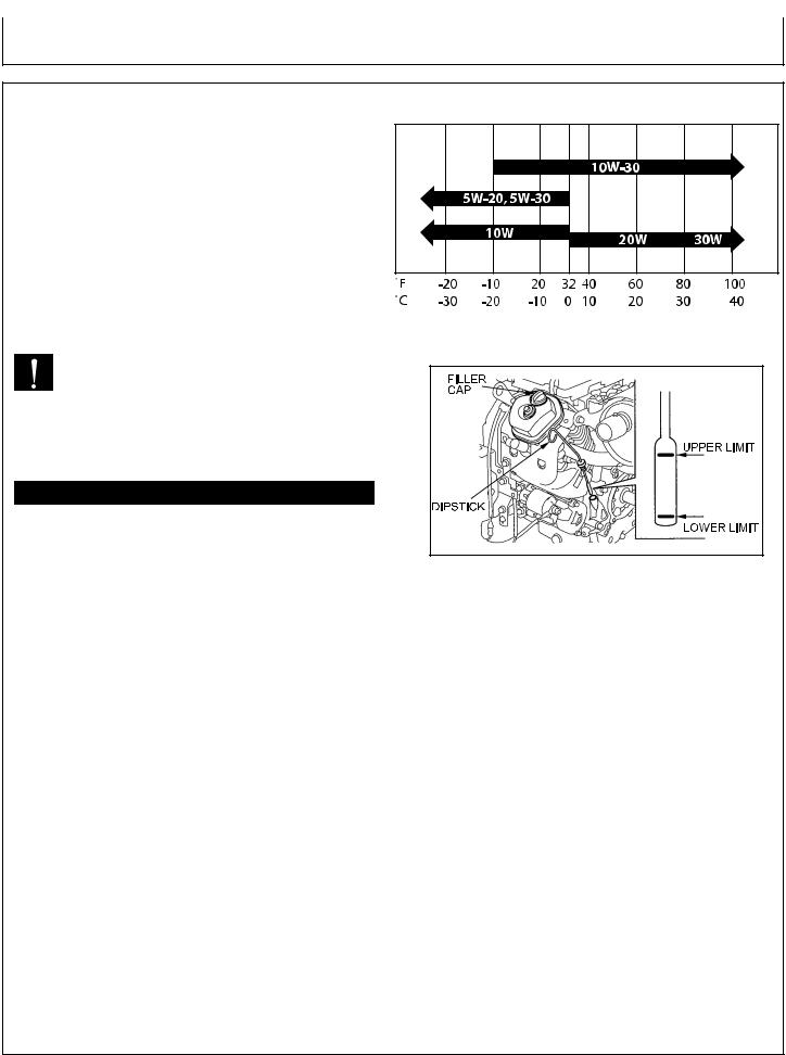
Oil is a major factor affecting performance and service life. Use 4-stroke automotive detergent oil.
Recommended Oil: Use 4-stroke motor oil that meets or exceeds the requirements for API service classification SJ, SL, or equivalent. Always check the API service label on the oil container to be sure it includes the letters SJ, SL, or equivalent.
SAE 10W-30 is recommended for general use. Other viscosities shown in the chart may be used when the average temperature in your area is within the indicated range. (Fig. 1)
CAUTION: THIS ENGINE CRANKCASE IS NOT FILLED WITH OIL AT THE FACTORY, SO BE SURE TO FILL IT BEFORE OPERATING THE ENGINE.
ENGINE OIL CAPACITY
MODEL # |
Liters |
Quart |
Ounces |
AC-G13010SE |
1.5 |
1.6 |
52.5 |
AC-G14010HE |
1.8 |
1.9 |
60.9 |
TEMPERATURE CHART
(Fig. 1)
To fill with oil: |
(Fig. 2) |
|
1.Level the engine to ensure accurate inspection and to prevent overfilling.
2.Remove the dipstick and wipe it clean.
3.Fully insert the dipstick, then remove it to check the oil level.
4.If the oil level is low, remove the oil filler cap, and fill to the upper limit mark on the dipstick with the recommended oil. (Fig. 2)
5.Reinstall the dipstick and filler cap.
NOTE: Running the engine with a low oil level can cause engine damage.
The Oil Alert system (applicable types) will automatically stop the engine before the oil level falls below the safe limit. However, to avoid the inconvenience of an unexpected shutdown, always check the engine oil level before startup.
Operator’s Manual |
15 |

Preparing the Generator
FUELING
WARNING: EXPLOSIVE FUEL!
GASOLINE IS EXTREMELY FLAMMABLE
AND ITS VAPORS CAN EXPLODE IF
IGNITED.
STORE GASOLINE ONLY IN APPROVED
CONTAINERS, IN WELL VENTILATED,
UNOCCUPIED BUILDINGS AND AWAY
FROM SPARKS OR FLAMES.
DO NOT FILL THE FUEL TANK WHILE THE
ENGINE IS HOT OR RUNNING, SINCE
SPILLED FUEL COULD IGNITE IF IT
COMES IN CONTACT WITH HOT PARTS OR
SPARKS FROM IGNITION. DO NOT START
THE ENGINE NEAR SPILLED FUEL.
NEVER USE GASOLINE AS A CLEANING
AGENT.
WARNING: DO NOT OVERFILL THE FUEL TANK,
LEAVE ROOM FOR THE FUEL TO EXPAND.
General Recommendations
•Purchase gasoline in small quantities and store in clean, approved containers.
•To minimize gum deposits in your fuel system and to insure easy starting, do not use gasoline left over from the previous season.
•Do not add oil to the gasoline.
Fuel Type
•For best results use only clean, fresh, unleaded gasoline with a pump sticker octane rating of 87 or higher.
•Unleaded gasoline is recommended as it leaves less combustion chamber deposits.
GASOLINE/ALCOHOL BLENDS:
Gasohol (up to 10% ethyl alcohol, 90% unleaded gasoline by volume) is approved, as a fuel. Other gasoline/alcohol blends are not approved.
GASOLINE/ETHER BLENDS:
Methyl Tertiary Butyl Ether (MTBE) and unleaded gasoline blends (up to a maximum of 15% MTBE by volume) are approved as a fuel. Other gasoline/ether blends are not approved.
16 |
Operator’s Manual |
Preparing the Generator
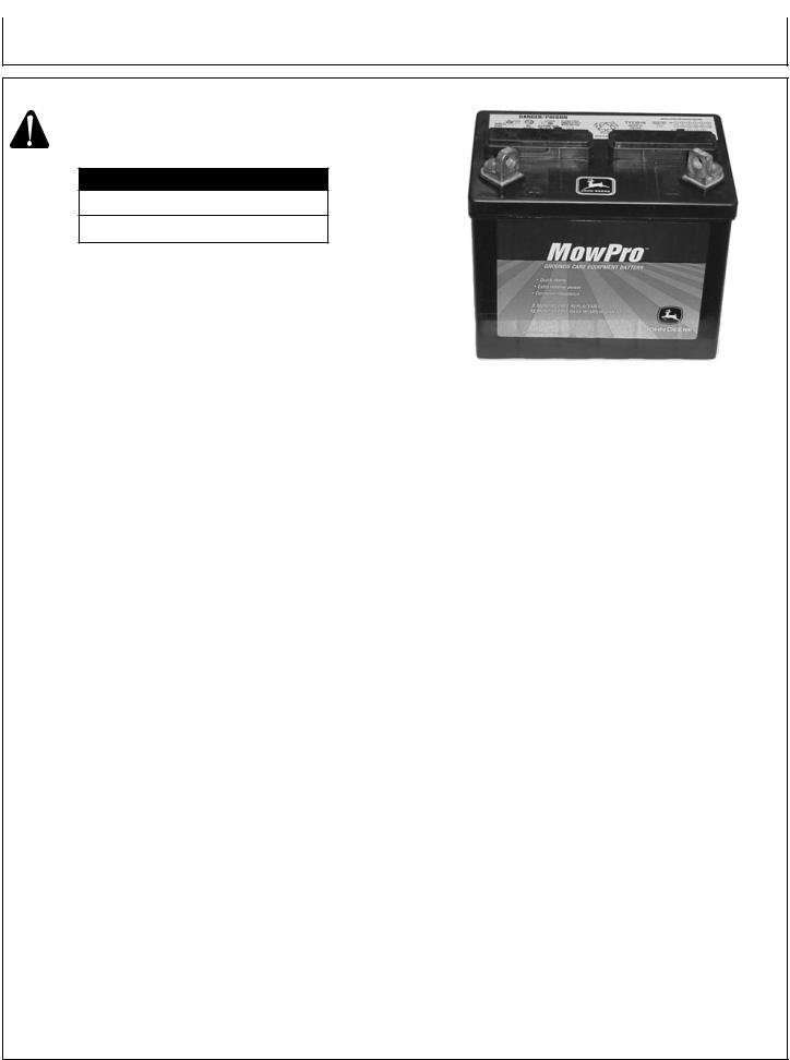
BATTERY INSTALLATION
WARNING: SHOULD ONLY BE DONE BY AN
AUTHORIZED DEALER.
BATTERY REPLACEMENT #
JOHN DEERE TY23018 (DRY)
JOHN DEERE SWGT-H (WET)
HIGH ALTITUDE
At high altitude, the standard carburetor air/fuel mixture will be too rich. Performance will decrease, and fuel consumption will increase. A very rich mixture will also foul the spark plug and cause hard starting. Operation at an altitude that differs from that at which this engine was certified, for extended periods of time, may increase emissions.
High altitude performance can be improved by specific modifications to the carburetor. If you always operate your generator at altitudes above 5,000 feet (1,500 meters), have your dealer perform this carburetor modification. This engine, when operated at high altitude with the carburetor modifications for high altitude use, will meet each emission standard throughout its useful life.
Even with carburetor modification, engine horsepower will decrease about 3.5% for each 1,000-foot (300-meter) increase in altitude. The effect of altitude on horsepower will be greater than this if no carburetor modification is made.
NOTE:When the carburetor has been modified for high altitude operation, the air/fuel mixture will be too lean for low altitude use. Operation at altitudes below 5,000 feet (1,500 meters) with a modified carburetor may cause the engine to overheat and result in serious engine damage.
For use at low altitudes, have your servicing dealer return the carburetor to original factory specifications.
Operator’s Manual |
17 |
Operation
OPERATION
NOTE: Read Operator’s Manual carefully before operating this unit. Be certain to block the wheels to prevent the unit from moving while operating. Always make sure the unit is level and properly grounded. Check engine oil before starting.
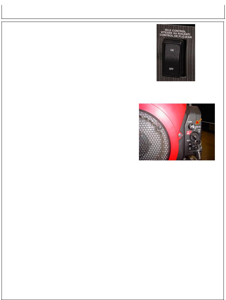
1.Turn the idle control switch to the OFF position. (See Fig. 3)
2.Move choke lever to full choke. If re-starting a warm engine, the choke should be left in the off position. (See Fig. 4)
3.Turn the key to the START position, hold until engine starts.
4.When the engine starts, release key, allowing it to return to the ON position.
NOTE: Do not crank the engine continuously for more than 30 seconds at a time. If the engine does not start, allow for a 3 minute cool down period between starting attempts. Failure to follow these guidelines can damage the starter motor.
If the starter does not turn the engine over, shut off the starter immediately. Do not make further attempts to
start the engine until the condition is corrected. Do not jump start using another battery.
5.Slowly move choke lever to no choke.
6.Allow unit to run two (2) minutes to warm-up.
7.Test the GFCI receptacle(s) on the unit. Push the test button. The reset button should pop out and there should be no power at the receptacle. Apply a test load or lamp to each receptacle to verify. IF THE RESET BUTTON DOES NOT POP OUT, DO NOT USE THE RECEPTACLES(S). SEE DEALER FOR SERVICE IMMEDIATELY.
8.If GFCI receptacle(s) test correctly, firmly push the reset button to restore power.Adistinctive click should be heard or felt when this is complete. IF THE RECEPTACLE(S) DO NOT RESET PROPERLY, DO NOT USE THE RECEPTACLE(S). SEE DEALER FOR SERVICE IMMEDIATELY.
9.Turn idle control switch to ON position. Loads can now be applied to unit.
NOTE: This engine is equipped with a “Low Oil” shutdown system for engine protection. The engine stops when the oil level gets too low. The engine will not restart without adding oil. Refer to Preparing the Generator; Engine Fuel Capacity for instructions on adding oil.
(Fig. 3)
(Fig. 4)
18 |
Operator’s Manual |

Operating the Generator
SHUTDOWN
1.Remove all load by turning off electrical appliances and unplugging electric cords.
2.Allow engine to run at idle speed to cool for two (2) minutes.
NOTE: Failure to allow the engine to cool at idle for two (2) minutes may result in damage to the generator.
3. Turn the engine key to the OFF position.
CONTROLS
OIL WARNING DEVICE:
NOTE: This engine is equipped with a “Low Oil” shutdown system for engine protection. The engine stops when the oil level gets too low. The engine will not restart without adding oil. If the unit is tilted too much during operation, it may suddenly stop even though the oil level is not low.
Check the engine oil before restarting the engine. If the unit is tilted, level the engine, then check the oil before restarting the engine.
CONTROL PANEL :
The generators are equipped with the following items:
-Idle Control Switch
-Hour Meter
-Volt Meter
-Circuit Breakers
-Two 125 Volt, 20 Amp, Duplex (3 outlets), GFCI protected receptacles.
-One 125 Volt, 30 Amp, Locking Type Receptacle.
-One 125/250 Volt, 30 Amp, Locking Type Receptacle.
-One 125/250 Volt, 50 Amp, Locking Type Receptacle.
NOTE:The 125 Volt, 30Amp; 125/250 Volt, 30Amp and 125/250 Volt, 50 Amp locking receptacles ARE NOT GROUND FAULT PROTECTED. If ground fault protection on these receptacles is necessary or desired, external protection devices must be used. Refer to the section on “Ground Fault Interrupter” for more information.
WARNING: NEVER EXCEED THE RATING OFA RECEPTACLE. These receptacles are protected against overloads by resetting magnetic type circuit breakers. If a circuit breaker trips, the cause should be determined and corrected prior to continuing use.
Operator’s Manual |
19 |

Operating the Generator
CONTROLS
HOUR METER:
These generators are equipped with an hour meter that records run time for the unit. This is very useful in scheduling maintenance. See periodic maintenance chart for suggested maintenance schedule.
VOLT METER:
These generators are equipped with a volt meter. The volt meter is used to monitor the unit for proper voltage.
IDLE CONTROL OPERATION:
The idle control is factory installed. This electrical device is designed to let the engine run at fuel saving low idle speed when the generator is not loaded, and at full normal governed speed when a load is applied. The idle system overrides the engine governor to provide idle speed. When a load is applied, the electronic circuit reacts to de-energize the idle system so that the engine can resume full governed operating speed.
The idle control system controls the engine speed in the following manner:
1.With the idle control switch in the “OFF” position, start the engine.
2.After one or two minute warm up period, apply load and move the switch to the “ON” position. The engine will throttle back to idle speed following a 5-8 second delay.
3.When a load is applied to the generator, the idle control system becomes de-energized. The engine then accelerates to normal operating speed, controlled by the governor.
4.When the load is removed, the idle system becomes re-energized and throttles the engine back to idle speed after a 5-8 second delay.
NOTE: While the engine is idling, the generator voltage is automatically reduced to reduce generator temperatures. The voltage will return to normal levels immediately upon the application of load.
20 |
Operator’s Manual |
Operating the Generator
CONTROLS
CABLE SIZE:
Equipment damage can result from low voltage. Therefore, to prevent excessive voltage drop between the generator and the equipment, the cable should be of adequate gauge for the length used. The cable selection chart gives the maximum cable lengths for various gauges of wire which can adequately carry the loads shown.
CURRENT |
LOAD IN WATTS |
|
MAXIMUM CABLE LENGTH (FEET) |
|
|||
IN AMPS |
120 VOLTS |
240 VOLTS |
#8 WIRE |
#10 WIRE |
#12 WIRE |
#14 WIRE |
#16 WIRE |
|
|
|
|
|
|
|
|
2.5 |
300 |
600 |
|
1000 |
600 |
375 |
250 |
5 |
600 |
1200 |
|
500 |
300 |
200 |
125 |
|
|
|
|
|
|
|
|
7.5 |
900 |
1800 |
|
350 |
200 |
125 |
100 |
10 |
1200 |
2400 |
|
250 |
150 |
100 |
50 |
15 |
1800 |
3600 |
|
150 |
100 |
65 |
|
20 |
2400 |
4800 |
175 |
125 |
75 |
50 |
|
25 |
3000 |
6000 |
150 |
100 |
60 |
|
|
30 |
3600 |
7200 |
125 |
65 |
|
|
|
40 |
4800 |
9600 |
90 |
|
|
|
|
|
|
|
|
|
|
|
|
ELECTRIC MOTOR LOADS:
It is characteristic of common electric motors in normal operation to draw up to six times their running current while starting. This table may be used to estimate the watts required to start “CODE G” electric motors.
CAUTION: IF AN ELECTRIC MOTOR FAILS TO START OR
REACH RUNNING SPEED, TURN OFF THE
APPLIANCE OR TOOL IMMEDIATELY TO AVOID
EQUIPMENT DAMAGE. ALWAYS CHECK THE
REQUIREMENTS OF THE TOOL OR APPLIANCE
BEING USED COMPARED TO THE RATED OUTPUT
OF THE GENERATOR.
|
|
WATTS REQUIRED TO START MOTOR |
||
MOTOR (H.P.) |
RUNNING WATTS |
REPULSION INDUCTION |
CAPACITOR |
SPLIT PHASE |
|
|
|
|
|
1/8 |
275 |
600 |
850 |
1200 |
1/6 |
275 |
600 |
850 |
2050 |
|
|
|
|
|
1/4 |
400 |
850 |
1050 |
2400 |
1/3 |
450 |
975 |
1350 |
2700 |
1/2 |
600 |
1300 |
1800 |
3600 |
|
|
|
|
|
3/4 |
850 |
1900 |
2600 |
|
1 |
1100 |
2500 |
3300 |
|
|
|
|
|
|
Operator’s Manual |
21 |

Troubleshooting
Symptom |
Problem |
Engine will not start. |
Engine switch is off. |
|
Fuel Tank empty. |
|
Inadequate engine oil. |
No spark at spark plug.
Generator has no output. |
Circuit breakers tripped. |
|
Inadequate cord sets or |
|
extension cords. |
Solution
Turn engine switch to the ON position.
Fill tank per instructions in this manual.
Check oil level. This engine is equipped with a low oil sensor. The engine cannot be started unless the oil level is above the prescribed lower limit.
Remove the spark plug cap. Clean any dirt from around the plug base, then remove the spark plug. Install the spark plug in the plug cap. Turn the engine switch on.
Grounding the electrode to any engine ground, pull the recoil starter to see if sparks jump across the gap. If there is no spark, replace the plug.
Reinstall the plug and start engine according to instructions in this manual.
Consult John Deere Customer
Service.
Reset circuit breakers.
Check cord sets or extension cords capabilities in section Controls; Cable Size in this manual. Consult John Deere Customer Service.
22 |
Operator’s Manual |

Service
MAINTENANCE
Keep all air vents clear.
Keep the generator clean. DO NOT spray with water.
Periodically check all fasteners and tighten, see the periodic maintenance chart.
GFCI TEST RECORDS:
As with any other safety devices, the GFCIs supplied with these generators must be checked every month to insure that they are functioning properly. To test the GFCIs, follow the instructions and then enter the date of the test below.
1.With the generator running and the idle control switch in the “START” position, push the “TEST” button. The “RESET” button should pop out. This should result in the power being off at both outlets of the duplex receptacle. Verify this by plugging a test lamp into each outlet.
WARNING: IF THE RESET BUTTON DOES NOT POP OUT, DO NOT USE THE RECEPTACLE(S). SEE AUTHORIZED JOHN DEERE CUSTOMER SERVICE REPRESENTATIVE FOR SERVICE IMMEDIATELY.
2.If the GFCI test correctly, restore power by FIRMLY pushing the “RESET” button back in until you hear or feel a distinctive “click”. IF THE GFCI FAILS TO RESET PROPERLY, DO NOT USE EITHER OUTLET OF THE DUPLEX RECEPTACLE. Have the unit serviced by an authorized John Deere Customer Service Representative immediately.
3.High vibration or severe mechanical shock loads may cause the GFCIs to trip. IF EITHER GFCI TRIPS BY ITSELF AT ANY TIME, reset it and perform test procedures 1 and 2.
4.Repeat steps 1-3 for the second GFCI.
WARNING: ALTHOUGH THE ABOVE TEST PROCEDURES WILL INDICATE PROPER GFCI OPERATION ON AN UNGROUNDED OR IMPROPERLY GROUNDED GENERATOR, THE GENERATOR MUST STILL
BE GROUNDED PER THE GROUNDING INSTRUCTIONS LISTED ON PAGE 14 FOR THE GFCI TO FUNCTION PROPERLY AND PROTECT THE USER FROM ELECTRICAL FAULTS.
Year |
Jan. |
Feb. March April May |
June July |
Aug. Sept. Oct. |
Nov. Dec. |
NOTE: Situations exist where a GFCI will not afford any protection against the hazards of electrical shock. EXAMPLE: if a person touches two or more conductors from a damaged cord set and is not in direct contact with the ground, he or she may receive a shock. Since there is no path to ground for a ground fault current to flow through, the GFCI will not operate and serious injury may result.
The GFCI are merely an added safety feature. There are no substitutes for good safety precautions, correct electrical practices and proper maintenance of cords, equipment and connections.
Operator’s Manual |
23 |

Service
MAINTENANCE
EVAPORATIVE EMISSION COMPONENTS:
The unit you have purchased includes the following components that are in compliance with 2011 California Air Resources Board Evaporative Emission Standards;
1.Fuel Hose
2.Fuel Hose Fittings
These components should be inspected on a daily basis for cracks, leaks, and abnormal wear. If cracking, leaks or abnormal wear has occurred, the components should be replaced immediately.
IDLE CONTROL ADJUSTMENT:
NOTE: The automatic idle speed is set between 2550 and 2950 RPM.
The idle speed has been pre-set at the factory and should rarely require readjustment. We recommend that all adjustments of this nature be made by a John Deere Customer Service Representative.
Erratic idle operation of the engine usually indicates a need for carburetor adjustment to provide a smooth idle. The idle control will not function properly when the idle speed is below the recommended limits or the carburetor is improperly adjusted.
HAVE THE UNIT SERVICED BY AN AUTHORIZED
JOHN DEERE CUSTOMER SERVICE
REPRESENTATIVE.
24 |
Operator’s Manual |

Service
MAINTENANCE
ENGINE:
The engine for this generator is governed to operate at speeds close to 3600 RPM (60Hz) throughout the operating load range. The no load speed (before a load is applied) will be just a bit higher than the load speed and is normally set to 3750 RPM.
WARNING: DO NOT TAMPER WITH THE GOVERNOR MECHANISM, CHANGE THE SETTING EXPERIMENTALLY, OR PUSH THE THROTTLE OPEN IN AN ATTEMPT TO GENERATE MORE ELECTRICALCURRENT;EQUIPMENTDAMAGE OR PERSONAL INJURY MAY RESULT.
GOVERNOR SPEED ADJUSTMENT SHOULD BEMADEONLYBYAJOHNDEERECUSTOMER SERVICE REPRESENTATIVE.
CHECKING ENGINE OIL:
Check oil level before each operation and ensure that it is maintained per Preparing the Generator; Engine Oil Capacity section.
CHANGING ENGINE OIL:
Change oil after the first 20 hours of operation. Thereafter it should be changed every 100 hours.
1.Make sure the unit is on level ground. Drain the used oil when the engine is warm. Warm oil drains quickly and completely.
2.Stop the engine.
3.Place a suitable container below the engine to catch the used oil, then remove the filler cap, drain bolt and washer. (See Fig. 5)
CAUTION: OIL BEING DRAINED MAY BE HOT. TO REDUCE THE RISK OF BURN INJURY, HANDLE WITH CARE. DISPOSE OF USED OIL PROPERLY.
4.Allow the used oil to drain completely, then reinstall the drain bolt and new washer, and tighten the drain bolt securely.
Dispose of used motor oil in a manner that is compatible with the environment.We suggest you take used oil in a sealed container to your local recycling center or service station for reclamation. Do not throw it in the trash, pour it on the ground, or down a drain.
5.With the engine in a level position, fill to the upper limit mark on the dipstick with the recommended oil.
NOTE: Running the engine with a low oil level can cause engine damage.
The Oil Alert system (applicable types) will automatically stop the engine before the oil level falls below the safe limit. However, to avoid the inconvenience of an unexpected shutdown, fill to the upper limit, and check the oil level regularly.
6. Reinstall the filler cap and dipstick securely. (Fig. 6)
(Fig. 5)
(Fig. 6)
Operator’s Manual |
25 |
Service
MAINTENANCE
AIR CLEANER:
WARNING: RISK OF FIRE OR EXPLOSION. DO NOT USE GASOLINE OR LOW FLASHPOINT SOLVENTS TO CLEAN THE ELEMENT. CLEAN THE ELEMENT IN A WELL VENTILATED AREA. ENSURE THAT NO SPARKS OR FLAMES ARE NEAR THE WORKING AREA, THIS INCLUDES ANY APPLIANCE WITH A PILOT LIGHT.
CAUTION: NEVER RUN THE ENGINE WITHOUT THE AIR FILTER, SERIOUS DANGER
CAN RESULT.
Check the air cleaner daily or before starting the engine. Check for and correct heavy buildup of dirt and debris along with loose or damaged components.
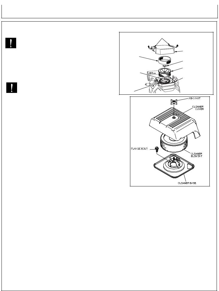
1.Release the two latch tabs or remove the wing nut from the air cleaner cover, and remove the cover. (Fig. 7)
2.Remove the paper filter and foam filter element from the air cleaner case. (if applicable)
3.Remove the foam filter from the paper filter element.
4.Inspect air filter elements, and replace if damaged.
5.Clean the air filter elements if they are to be reused:
FOAM FILTER ELEMENT: Wash the foam filter element in warm water with detergent. Rinse the foam filter element thoroughly until all traces of detergent are eliminated. Squeeze out excess water, but do not wring.Allow the foam filter element to air dry.
Saturate the foam filter element with new engine oil. Squeeze out all excess oil. DO NOT put engine oil on the foam damper.
NOTE:Clean the foam filter element every 25 hours of operation (more often under extremely dusty or dirty condition)
PAPER FILTER ELEMENT: Do not wash the paper filter element or use pressurized air, as this will damage the element. Clean by gently tapping the element to remove dust. Replace the element if damaged, bent or extremely dirty. Handle new element carefully; do not use if the sealing surfaces are bent or damaged.
NOTE: Replace the paper filter element every 100 hours (more often under extremely dusty conditions.)
6.Wipe dirt from the inside of the air cleaner body and cover, using a moist rag. Be careful to prevent dirt fromentering the air chamber that leads to the carburetor.
7.Place the foam air filter element in the air cleaner cover. If applicable, reinstall the paper air filter element and cover to the air cleaner case. Replace cover securely.
Air Cleaner Cover Latch
Air Cleaner Cover
Foam Filter
Element Wing Nut
Paper Filter Element
Air Chamber
Air Cleaner Case
Packing
(Fig. 7)
26 |
Operator’s Manual |

Service
MAINTENANCE
CLEANING AND GAPPING SPARK PLUG:
If the plug is contaminated with carbon, remove it using a plug cleaner or wire brush.
Check the spark plug gap and reset it if necessary. The spark plug gaps are listed below. To change the gap, bend the sideelectrode only, using a spark plug tool. (Fig. 8)
Install and tighten the spark plug. Connect the spark plug lead.
Recommended Spark Plug:
Engine |
Subaru |
|
Honda |
Spark Plug |
NGK BP6ES |
|
NGK ZFR5F |
Spark Plug Gap |
0.7 - 0.8 mm (0.03 in.) |
||
Torque - New |
|
8.7-10.9 ft-lb |
|
Torque - Retighten |
|
16.6-19.5 ft-lb |
|
Spark Plug Gap (See recommendations)
(Fig. 8)
SPARK ARRESTOR:
If the generator has been running, the muffler will be very hot. Allow it to cool before proceeding.
NOTE: Remove and clean spark arrester every 100 hours or as necessary.
NOTE: Product users on United States forest service land, and in some states, must comply with fire prevention regulations.
Clean the spark arrester as follows: (Fig. 9 and 10)
1.Remove the screw from the muffler and remove the spark arrester.
2.Use a brush to remove carbon deposits from the spark arrester screen. Be careful to avoid damaging the screen.
The spark arrester must be free of breaks and holes. Replace the spark arrester if it is damaged.
3.Install the spark arrester and muffler protector in the reverse order of disassembly.
Spark arrestors are available from your local John Deere Customer Service Representative. Other user requirements may apply, check with your Federal, State or local authorities.
(Fig. 9)
(Fig. 10)
Operator’s Manual |
27 |

Service
MAINTENANCE
PERIODIC MAINTENANCE CHART:
To ensure satisfactory operation over an extended period of time, an engine requires normal maintenance at regular intervals. The Periodic Maintenance Chart below shows periodic inspection and maintenance items and suitable intervals. The bullet mark designates that the corresponding item should be performed at that interval.
NOTE: Some adjustments require the use of special tools or other equipment. An electronic tachometer will facilitate setting idle and running speeds.
|
Daily |
Every |
Every |
Every |
Before |
|
|
|
25hrs. |
100 hrs. |
200 hrs. |
Storage |
|
|
|
|
|
|
|
|
Check fuel |
• |
|
|
|
|
|
Check engine oil |
• |
|
|
|
|
|
Check for loose or lost nuts and bolts |
• |
|
|
|
|
|
Check for leaks |
• |
|
|
|
|
|
Check cylinder and head fins for |
|
|
|
|
|
|
dust and dirt |
• |
|
|
|
|
|
Check battery electrolyte level |
• |
|
|
|
|
|
Check fuel lines (replace if necessary) |
• |
|
|
|
|
|
Clean air cleaner foam element (**) |
|
• |
|
|
|
|
Tighten nuts and bolts (*) |
|
|
• |
|
|
|
|
|
|
|
|
|
|
Change engine oil (*) |
|
|
• |
|
|
|
Clean fuel filter |
|
|
• |
|
|
|
Replace air cleaner paper element (**) |
|
|
• |
|
|
|
Clean dust and dirt from |
|
|
|
|
|
|
cylinder and cylinder head fins (**) |
|
|
• |
|
|
|
|
|
|
|
|
|
|
Clean and regap spark plug |
|
|
|
• |
|
|
Add fuel stabilizer |
|
|
|
|
• |
|
|
|
|
|
|
|
|
Run unit dry |
|
|
|
|
• |
|
|
|
|
|
|
|
|
* Perform these operations after the first 5 hours of use, then at the recommended intervals.
** Service more frequently under dusty conditions.
NOTE: These items must be performed with the proper tools. See your John Deere Customer Service Representative for service, unless you have the proper equipment and mechanical proficiency.
28 |
Operator’s Manual |

Storage
Service
STORING GENERATOR
SHORT TERM (1-6 months):
1.Add gasoline conditioner and stabilizer at the specified concentration.
2.Run the unit for two (2) minutes to ensure the mixed fuel is in the entire fuel system. Close the fuel valve and run the unit until it stops.
3.Remove the spark plug, pour 1-2 teaspoons (5-10cc) of engine oil into the cylinder, slowly pull the starter handle 2 or 3 times, reinstall the spark plug and tighten securely.
4.Clean the exterior surface of the generator and apply a rust inhibitor.
5.Store the generator in a dry, well ventilated place.
LONG TERM (More than 6 months):
1.Add gasoline conditioner and stabilizer at the specified concentration.
2.Run the generator until the fuel tank and carburetor are dry. As the engine is beginning to die, move the choke lever to the choke position.
NOTE: Turn off the idle control to decrease the run time.
3.Remove the spark plug, pour 1-2 teaspoons (5-10cc) of engine oil into the cylinder, slowly pull the starter handle 2 or 3 times, reinstall the spark plug and tighten securely.
4.Clean the exterior surface of the generator and apply a rust inhibitor.
5.Store the generator in a dry, well ventilated place.
WARNING: FUEL SHOULD BE DRAINED IN A
WELLVENTILATEDAREAAND STORED
IN A CONTAINER APPROVED FOR
GASOLINE.
Operator’s Manual |
29 |
 Loading...