


6059T
AIR FORCE TO 38G1-96-2
MARINE CORPS TM 2815-24/5
TECHNICAL MANUAL
UNIT, DIRECT SUPPORT AND GENERAL SUPPORT
MAINTENANCE INSTRUCTIONS
DIESEL ENGINE
MODEL 6059T
6 CYLINDER 5.9 LITER
NSN: 2815-01-350-2209
ARMY TM 9-2815-256-24
This copy is a reprint which includes current pages from Change 1.
HEADQUARTERS, DEPARTMENTS OF THE ARMY, AIR FORCE
AND HEADQUARTERS, U.S. MARINE CORPS
15 SEPTEMBER 1993

ARMY TM 9-2815-256-24
AIR FORCE TO 38G1-96-2
MARINE CORPS TM 2815-24/5
C3
CHANGE HEADQUARTERS
DEPARTMENTS OF THE ARMY, AIR FORCE
AND HEADQUARTERS, U.S. MARINE CORPS
NO. 3 WASHINGTON, D.C., 30 October 1996
Unit, Direct Support and General Support
Maintenance Instructions
DIESEL ENGINE
MODEL 4059T
6 CYLINDER 5.9 LITER
NSN: 2815-01-350-2209
DISTRIBUTION STATEMENT A: Approved for public release; distribution is unlimited
TM 9-2815-256-24/TO 38G1-96-2/TM 2815-24/5, 15 September 1993, is changed as follows:
1. Remove and insert pages as indicated below. New or changed text material is indicated by a vertical bar in the
margin. An illustration change is indicated by a miniature pointing hand.
Remove pages Insert pages
i and ii i and ii
3-1 and 3-2 3-1 and 3-2
3-21 through 3-30 3-21 through 3-30
3-33 through 3-38 3-33 through 3-38
3-43 and 3-44 3-43 and 3-44
3-49 and 3-50 3-49 and 3-50
3-61 through 3-66 3-61 through 3-66
3-77 through 3-84 3-77 through 3-84
3-87 through 3-90 3-87 through 3-90
3-121 and 3-122 3-121 and 3-122
3-161 through 3-168 3-161 through 3-168
3-173 through 3-178 3-173 through 3-178
2. Retain this sheet in front of manual for reference purposes.

ARMY TM 9-2815-256-24
AIR FORCE TO 38G1-96-2
MARINE CORPS-TM 2815-24/5
C2
CHANGE HEADQUARTERS, DEPARTMENTS OF
THE ARMY, THE AIR FORCE AND
HEADQUARTERS, U.S. MARINE CORPS
NO. 2 WASHINGTON, D.C., 31 OCTOBER 1995
Unit, Direct Support and
General Support Maintenance Instructions
DIESEL ENGINE
MODEL 6059T
6 CYLINDER 5.9 LITER
NSN: 2815-01-350-2209
DISTRIBUTION STATEMENT A: Approved for public release; distribution is unlimited
TM 9-2815-256-24/TO 38G1-96-2/TM 2815-24/5, 15 September 1993, is changed as follows:
1. Remove and insert pages as indicated below. New or changed text material is indicated by a vertical bar in the
margin. An illustration change is indicated by a miniature pointing hand.:
Remove pages Insert pages
3-27 and 3-28 3-27 and 3-28
3-139 and 3-140 3-139 and 3-140
2. Retain this sheet in front of manual for reference purposes.

ARMY TM 9-2815-256-24
AIR FORCE TO 38G1-96-2
MARINE CORPS TM 2815-24/5
By Order of the Secretaries of the Army, Air Force and Navy (including Marine Corps):
DENNIS J. REIMER
General, United States Army
Official: Chief of Staff
YVONNE M. HARRISON
Administrative Assistant to the
Secretary of the Army
01212
RONALD R. FOGELMAN
General, USAF
Chief of Staff
C2
HENRY VICCELLIO, JR.
General, USAF
Commander, Air Force Materiel Command
J. E. BUFFINGTON
Rear Admiral, CEC. US Navy
Commander
Navy Facilities Engineering
Command
D. R. BLOOMER
Colonel, USMC
Director, Program Support
Marine Corps Systems Command
DISTRIBUTION:
To be distributed in accordance with DA Form 12-25-E, block no. 5145, requirements for TM 9-2815-256-24.

ARMY TM 9-2815-256-24
AIR FORCE TO 38G1-96-2
MARINE CORPS TM 2815-24/5
C1
CHANGE HEADQUARTERS
DEPARTMENTS OF THE ARMY, AIR FORCE
AND HEADQUARTERS U.S. MARINE CORPS
NO. 1 WASHINGTON, D.C., 15 DECEMBER 1993
TECHNICAL MANUAL
Unit, Direct Support and General Support
Maintenance Instructions
DIESEL ENGINE
MODEL 6059T
6 CYLINDER 5.9 LITER
NSN: 2815-01-350-2209
DISTRIBUTION STATEMENT A: Approved for public release; distribution is unlimited.
TM 9-2815-256-24/TO 38G1 -96-2/TM 2815-24/5, 15 September 1993, is changed as follows:
1. Remove and insert pages as indicated below. New or changed text material is indicated by a vertical bar in the
margin. An illustration change is indicated by a miniature pointing hand.
Remove pages Insert pages
i and ii i and ii
- - - - - - - Appendix E
2. Retain this sheet in front of manual for reference purposes.

ARMY TM 9-2815-256-24
AIR FORCE TO 38G1 -96-2
MARINE CORPS TM 2815-24/5
By Order of the Secretaries of the Army, Air Force, and Navy (Including the Marine Corps):
GORDON R. SULLIVAN
General, United States Army
Official: Chief of Staff
MILTON H. HAMILTON
Administrative Assistant to the
Secretary of the Army
05837
MERRILL A. McPEAK
General, USAF
Chief of Staff
Official:
C1
RONALD W. YATES
General, USAF
Commander, Air Force Materiel Command
DAVID E BOTTORFF
Rear Admiral, CEC, US Navy
Commander
Navy Facilities Engineering
Command
D. R. BLOOMER
Colonel, USMC
Director, Program Support
Marine Corps Systems Command
DISTRIBUTION:
To be distributed in accordance with DA Form 12-25-E, block no. 5145, requirements for TM 9-2815-256-24.

For first aid, refer to FM 21-11.
The noise level when operating could cause hearing damage. Ear protection must be worn.
Where applicable, prior to performing engine maintenance, ensure batteries are disconnected.
ARMY TM 9-2815-256-24
AIR FORCE TO 38G1-96-2
MARINE CORPS TM 2815-24/5
SAFETY SUMMARY
Warning
Warning
Warning
If the engine has been operating and coolant is hot, allow engine to cool before you slowly loosen
filler cap and relieve pressure from cooling system. Failure to observe this warning could result in
severe personal injury.
Warning
Use care when rotating engine on engine maintenance stand. If necessary, use a lifting device to
avoid severe personal injury.
Warning
Do not drain coolant until the coolant temperature is below operating temperature prior to removal of
water pump. Severe personal injury can occur.
Warning
Exercise care when bench testing starter. Ensure metal objects do not contact connection points as
severe arcing will occur. Failure to observe this warning could result in personal injury.
a

ARMY TM 9-2815-256-24
AIR FORCE TO 38G1-96-2
MARINE CORPS TM 2815-24/5
SAFETY SUMMARY - Continued
Warning
After operating engine, allow exhaust system to cool before removal of turbocharger. Failure to
observe this warning could result in personal injury.
Warning
Compressed air used for cleaning can create airborne particles that may enter the eyes. Pressure
will not exceed 30 psig (207 kPa). Eye protection required.
Warning
Oil pressure regulating valve spring (3, FIGURE 3-50) is under pressure and can cause personal
injury when plug (1) is removed.
Warning
Cleaning solvent is flammable and toxic to eyes, skin, and respiratory tract. Skin/eye protection
required. Avoid repeated/prolonged contact. Good general ventilation is normally adequate.
Warning
Escaping diesel fuel under pressure can have sufficient force to penetrate the skin, causing serious
injury. Before disconnecting fuel lines, be sure to relieve pressure. Before applying pressure to the
system, be sure all connections are tight and lines, pipes, and hoses are not damaged. Keep hands
and body away from pinholes and nozzles which eject fuel under pressure. Use a piece of cardboard
or wood, rather than hands, to search for suspected leaks.
Warning
If any diesel fuel is injected into the skin, it must be surgically removed within a few hours by a
doctor familiar with this type injury or gangrene can result.
b

ARMY TM 9-2815-256-24
AIR FORCE TO 38G1-96-2
MARINE CORPS TM 2815-24/5
SAFETY SUMMARY - Continued
Warning
Diesel fuel is flammable and toxic to eyes, skin, and respiratory tract. Skin/eye protection required.
Avoid repeated/prolonged contact. Good general ventilation is normally adequate.
Warning
Diesel fuel and cleaning solvent are flammable and toxic to eyes, skin, and respiratory tract.
Skin/eye protection required. Avoid repeated/prolonged contact. Good general ventilation is
normally adequate.
Warning
If nuts (19, FIGURE 3-59) are removed prior to shaft/gear separation, fuel injection pump will fall out
which can cause personal injury and/or equipment damage.
Warning
Compressed air can be hazardous when not used properly.
Warning
The fuel nozzle tip should always be directed away from operator. Fuel from spray orifices can
penetrate clothing and skin causing serious personal injury. Enclosing nozzle in a transparent cover
is recommended.
Warning
Before applying pressure to fuel nozzle tester, be sure that all connections are tight, and that fittings
are not damaged. Fluid escaping from a very small hole can be almost invisible. Using a piece of
cardboard or wood, rather than hands, to search for suspected leaks.
c

ARMY TM 9-2815-256-24
AIR FORCE TO 38G1-96-2
MARINE CORPS TM 2815-24/5
SAFETY SUMMARY - Continued
Warning
If injured by escaping fuel, see a doctor immediately. Any fluid injected into skin must be surgically
removed within a few hours or gangrene can result.
Warning
Place a clear, protective shield around fuel nozzle spray zone during testing to avoid possible
personal injury from spray.
Warning
Ensure each end of cylinder head is supported on blocks of wood to prevent serious injury or death
when using valve spring compressor.
Warning
Block cylinder head (2, FIGURE 3-119) using a solid block of wood at each end of head for support
while using spring compressor to avoid personal injury.
Warning
Do not stand in front of valve springs while compressing them to avoid personal injury.
Warning
Caustic solutions are highly toxic to the skin, eyes, and respiratory tract. Avoid all contact. Skin and
eye protection and vapor control are required.
d

ARMY TM 92815-256-24
AIR FORCE TO 38G1-96-2
MARINE CORPS TM 2815-24/5
SAFETY SUMMARY - Continued
Warning
Flywheel is heavy. Provide adequate lifting device to support weight. Failure to follow this
procedure could result in personal injury.
Warning
Oil fumes or oil can ignite above 380° F (193° C) - Use a thermometer and do not exceed 360°F
(182°C). Do not allow a flame or heating element to be in direct contact with oil. Heat oil in a well
ventilated area. Plan a safe handling procedure to avoid bums.
Warning
Wear protective gloves to help prevent burns from handling hot ring gear.
Warning
Crankshaft is very heavy, do not attempt to remove crankshaft by hand. Use proper lifting
equipment.
e/(f blank)

ARMY TM 9-2815-256-24
AIR FORCE TO 38G1-96-2
MARINE CORPS TM 2815-24/5
TECHNICAL MANUAL HEADQUARTERS
DEPARTMENTS OF THE ARMY, AIR FORCE
AND HEADQUARTERS, U.S. MARINE CORPS
NO. 9-2815-256-24 WASHINGTON, D.C., 15 September 1993
Unit, Direct Support and General Support
Maintenance Instructions
DIESEL ENGINE
MODEL 4059T
6 CYLINDER 5.9 LITER
NSN: 2815-01-350-2209
REPORTING ERRORS AND RECOMMENDING IMPROVEMENTS
You can help improve this manual. If you find any mistakes or if you know of a way to improve these
procedures, please let us know.
(A) Mail your letter or DA Form 2028 (Recommended Changes to Publications and Blank Forms), or DA
Form 2028-2 located in the back of this manual directly to: Commander, US Army Aviation and Troop
Command, ATTN: AMSAT-I-MP, 4300 Goodfellow Blvd., St. Louis, MO 63120-1798. You may also
submit your recommended changes by E-mail directly to <mpmt%avma28@st-louis-emh7.army.mil>.
Instructions for sending an electronic 2028 may be found at the back of this publication immediately
preceding the hard copy 2028.
(F) Air Force - AFTO Form 22 Directly to: Commander, Sacramento Air Logistics Center, ATTN: TILBA,
McClellan AFB, CA 95652-5990 (AFMC).
(M) Marine Corps - NAVMC Form 10772 Directly to: Commander, Marine Corps Logistics Bases (Code
850), Albany, GA 31704-5000.
A reply will be furnished directly to you.
DISTRIBUTION STATEMENT A: Approved for public release; distribution is unlimited.
TABLE OF CONTENTS
PAGE
CHAPTER 1 INTRODUCTION .......................................................................................................... 1-1
Section I. General Information...................................................................................................... 1-1
Section II. Equipment Description and Data................................................................................... 1-1
Section III. Preparation for Use....................................................................................................... 1-4
CHAPTER 2 OPERATION................................................................................................................. 2-1
Section I. PRINCIPLES OF OPERATION..................................................................................... 2-1
Section II. OPERATING INSTRUCTIONS ..................................................................................... 2-1
CHAPTER 3 MAINTENANCE............................................................................................................ 3-1
Section I. PREVENTIVE MAINTENANCE CHECKS AND SERVICES (PMCS)............................. 3-1
Change 3 i

ARMY TM 9-2815-256-24
AIR FORCE TO 38G1-96-2
MARINE CORPS TM 2815-24/5
TABLE OF CONTENTS - continued
PAGE
Section II. Troubleshooting ............................................................................................................ 3-2
Section III. General Maintenance.................................................................................................... 3-15
Section IV. Cooling System Maintenance........................................................................................ 3-21
Section V. Electrical System Maintenance ..................................................................................... 3-27
Section VI. Intake and Exhaust System Maintenance...................................................................... 3-51
Section VII. Lubrication System Maintenance................................................................................... 3-61
Section VIII. Fuel System Maintenance............................................................................................. 3-76
Section IX. Cylinder Head Assembly Maintenance .......................................................................... 3-139
Section X. Flywheel and Housing Assembly Maintenance.............................................................. 3-159
Section XI. Crankshaft Pulley and Timing Gear Cover
Assembly Maintenance.............................................................................................. 3-164
Section XII. Camshaft Assembly Maintenance ................................................................................. 3-168
Section XIII. Idler Gears and Front Plate Assembly Maintenance...................................................... 3-174
Section XIV. Crankshaft and Main Bearings Maintenance.................................................................. 3-180
Section XV. Pistons, Connecting Rods, Cylinder Liners,
and Engine Block Maintenance.................................................................................. 3-190
APPENDIX A REFERENCES ............................................................................................................. A-1
APPENDIX B MAINTENANCE ALLOCATION CHART........................................................................ B-1
APPENDIX C EXPENDABLE/DURABLE SUPPLIES AND MATERIALS LIST..................................... C-1
APPENDIX D FABRICATION OF TOOLS........................................................................................... D-1
APPENDIX E MAINTENANCE PROCEDURES AND AUTHORIZED LEVEL OF MAINTENANCE...... E-1
INDEX ..................................................................................................................................... Index-1
Change 1 ii

ARMY TM 9-2815-256-24
AIR FORCE TO 38G1-96-2
MARINE CORPS TM 2815-24/5
LIST OF ILLUSTRATIONS
FIGURE PAGE
1-1. Engine Components......................................................................................................................... 1-3
3-1. Connecting Test Gage to Intake Manifold......................................................................................... 3-19
3-2. Thermostat and Housing .................................................................................................................. 3-22
3-3. Engine Oil Cooler Hoses .................................................................................................................. 3-24
3-4. Water Pump Assembly..................................................................................................................... 3-25
3-5. Battery Charging Alternator and Mounting Brackets.......................................................................... 3-28
3-6. Battery Charging Alternator Assembly.............................................................................................. 3-30
3-7. Stator and Rear Housing Separation ................................................................................................ 3-30
3-8. Testing Brush Assembly................................................................................................................... 3-31
3-9. Testing Diode-Trio............................................................................................................................ 3-31
3-10. Testing Rectifier Bridge.................................................................................................................... 3-32
3-11. Testing Stator Windings ................................................................................................................... 3-33
3-12. Testing Rotor.................................................................................................................................... 3-33
3-13. Battery Charging Alternator Test Circuit ........................................................................................... 3-34
3-14. Starter Bench Test Setup ................................................................................................................. 3-36
3-15. Starter Assembly.............................................................................................................................. 3-37
3-16. Disconnecting Lead Wire (Typical)................................................................................................... 3-38
3-17. Removing Through Bolts (Typical) ................................................................................................... 3-38
3-18. Removing Starter End Frame and Yoke Assembly (Typical)............................................................. 3-39
3-19. Removing Brushes........................................................................................................................... 3-40
3-20. Removing Armature......................................................................................................................... 3-40
3-21. Removing Housing (Typical) ............................................................................................................ 3-41
3-22. Removing Overrunning Clutch (Typical)........................................................................................... 3-41
3-23. Removing Steel Ball......................................................................................................................... 3-42
3-24. Removing Pinion, Retainer, and Rollers (Typical)............................................................................. 3-42
3-25. Removing Washer and Spring.......................................................................................................... 3-43
3-26. Checking Commutator Run-Out........................................................................................................ 3-43
3-27. Measuring Commutator OD.............................................................................................................. 3-44
3-28. Measuring Segment Mica Depth....................................................................................................... 3-44
3-29. Inspecting and Replacing Bearings................................................................................................... 3-45
3-30. Measuring Brush Length................................................................................................................... 3-45
3-31. Checking Overrunning Clutch........................................................................................................... 3-46
3-32. Starter Solenoid Test Circuit............................................................................................................. 3-46
3-33. Growler Test..................................................................................................................................... 3-47
3-34. Testing for Grounded Windings........................................................................................................ 3-47
3-35. Checking for Open Circuit Windings................................................................................................. 3-47
3-36. Checking Brush Holder..................................................................................................................... 3-48
3-37. Checking Field Coils......................................................................................................................... 3-48
3-38. Checking for Open Field Coil............................................................................................................ 3-49
iii

ARMY TM 9-2815256-24
AIR FORCE TO 38G1-96-2
MARINE CORPS TM 2815-24/5
LIST OF ILLUSTRATIONS - Continued
FIGURE PAGE
3-39. Installing Brushes............................................................................................................................. 3-49
3-40. Installing Cover On Yoke.................................................................................................................. 3-50
3-41. Installing Yoke.................................................................................................................................. 3-50
3-42. Turbocharger.................................................................................................................................... 3-52
3-43. Turbocharger Inspection Points........................................................................................................ 3-53
3-44. Exhaust Manifold.............................................................................................................................. 3-58
3-45. Intake Manifold................................................................................................................................. 3-60
3-46. Oil Filter and Cooler......................................................................................................................... 3-62
3-47. Removing Oil Filter Nipple ............................................................................................................... 3-63
3-48. Installing Oil Filter Nipple ................................................................................................................. 3-64
3-49. Driving Oil Filter Nipple.................................................................................................................... 3-64
3-50. Oil Pressure Regulating Valve and Oil Filler Assembly..................................................................... 3-66
3-51. Dipstick ............................................................................................................................................ 3-68
3-52. Oil Pan............................................................................................................................................. 3-69
3-53. Oil Pump Assembly.......................................................................................................................... 3-71
3-54. Measuring Oil Pump Axial Clearance............................................................................................... 3-72
3-55. Measuring Oil Pump Radial Clearance............................................................................................. 3-72
3-56. Oil Pressure Test Setup.................................................................................................................... 3-74
3-57. Oil Bypass Valve Installation............................................................................................................ 3-74
3-58. Fuel Filter and Fuel Supply Pump .................................................................................................... 3-78
3-59. Fuel Lines and Injection Pump Installation........................................................................................ 3-83
3-60. Flywheel Locking Tool...................................................................................................................... 3-85
3-61. Checking Timing Marks.................................................................................................................... 3-85
3-62. Fuel Infection Pump Gear Access (Cover Removed......................................................................... 3-86
3-63. Separating Gear and Shaft............................................................................................................... 3-86
3-64. Fuel Injection Pump Assembly ......................................................................................................... 3-89
3-65. Disassembly of Shut-Off Lever......................................................................................................... 3-90
3-66. Disassembly of Throttle Shaft Assembly........................................................................................... 3-90
3-67. Speed Droop Governor .................................................................................................................... 3-91
3-68. Disengaging Governor Linkage (Typical).......................................................................................... 3-92
3-69. Removing Metering Valve................................................................................................................ 3-92
3-70. Removing Vent Wire Screw ............................................................................................................. 3-93
3-71. Removing Transfer Pump Screw...................................................................................................... 3-93
3-72. Removing Transfer Pump End Cap.................................................................................................. 3-94
3-73. Fuel Injection Pump Hydraulic Head Assembly................................................................................. 3-95
3-74. Transfer Pump Regulator Components............................................................................................. 3-96
3-75. Removing Transfer Pump Blades..................................................................................................... 3-96
3-76. Removing End Cap Seal.................................................................................................................. 3-97
3-77. Removing Head Locating Screw....................................................................................................... 3-97
iv

ARMY TM 92815-256-24
AIR FORCE TO 38G1-96-2
MARINE CORPS TM 2815-24/5
LIST OF ILLUSTRATIONS - Continued
FIGURE PAGE
3-78. Removing Advance Screw Hole Plug............................................................................................... 3-98
3-79. Removing Spring Side Advance Plug............................................................................................... 3-98
3-80. Disassembling Governor .................................................................................................................. 3-99
3-81. Removing Shaft Retaining Nut......................................................................................................... 3-99
3-82. Removing Governor Arm ................................................................................................................. 3-100
3-83. Removing Rotor Retainers ............................................................................................................... 3-100
3-84. Removing Cam Ring (Typical).......................................................................................................... 3-101
3-85. Removing Delivery Valve................................................................................................................. 3-101
3-86. Removing Leaf Spring (Typical)....................................................................................................... 3-102
3-87. Removing Rollers (Typical) .............................................................................................................. 3-102
3-88. Removing Pumping Plungers (Typical)............................................................................................. 3-103
3-89. Delivery Valve Replacement............................................................................................................ 3-108
3-90. Installing Rollers and Shoes (Typical)............................................................................................... 3-109
3-91. Measuring Roller-To-Roller Dimension............................................................................................. 3-110
3-92. Installing Seals and Bearing ............................................................................................................. 3-112
3-93. Installing Protection Tube................................................................................................................. 3-113
3-94. Installing Governor Arm.................................................................................................................... 3-113
3-95. Installing Weights............................................................................................................................. 3-114
3-96. Installing Thrust Washer and Sleeve................................................................................................ 3-114
3-97. Inserting Hydraulic Head (Typical).................................................................................................... 3-115
3-98. Installing Metering Valve.................................................................................................................. 3-116
3-99. Installing Governor Linkage.............................................................................................................. 3-116
3-100. Alignment of Spacer......................................................................................................................... 3-117
3-101. Alignment of Shutoff Arm................................................................................................................. 3-118
3-102. Installing Throttle Shaft Assembly (Typical)...................................................................................... 3-118
3-103. Checking Clearance at Linkage Hook............................................................................................... 3-120
3-104. Installing Shutoff Cam...................................................................................................................... 3-121
3-105. Installing End Cap............................................................................................................................ 3-122
3-106. Installing Retaining Plate.................................................................................................................. 3-122
3-107. Installing Locking Head Bolts............................................................................................................ 3-123
3-108. Installing Pilot Tube Seal.................................................................................................................. 3-123
3-109. Fuel Injection Pump Installation........................................................................................................ 3-129
3-110. Checking Timing Marks.................................................................................................................... 3-129
3-111. Checking Injection Pump Gear Timing ............................................................................................. 3-130
3-112. Fuel Injection Nozzle........................................................................................................................ 3-133
3-113. Fuel Injection Nozzle Seals .............................................................................................................. 3-136
3-114. Valve Cover..................................................................................................................................... 3-139
3-115. Adjusting Valve Clearance ............................................................................................................... 3-140
3-116. Checking Valve Clearance ............................................................................................................... 3-141
v

ARMY TM 9-2815-256-24
AIR FORCE TO 38G1-96-2
MARINE CORPS TM 2815-24/5
LIST OF ILLUSTRATIONS - Continued
FIGURE PAGE
3-117. Installing Timing Pin......................................................................................................................... 3-141
3-118. Rocker Arm Assembly...................................................................................................................... 3-143
3-119. Cylinder Head Assembly .................................................................................................................. 3-147
3-120. Valve Face Angle............................................................................................................................. 3-150
3-121. Measuring Cylinder Head Thickness................................................................................................. 3-151
3-122. Valve Seat Bore Specifications ........................................................................................................ 3-155
3-123. Measuring Cylinder Liner Height....................................................................................................... 3-156
3-124. Cylinder Head Capscrew Tightening Sequence ................................................................................ 3-157
3-125. Flywheel and Housing Assembly ...................................................................................................... 3-161
3-126. Crankshaft Pulley............................................................................................................................. 3-164
3-127. Timing Gear Cover........................................................................................................................... 3-166
3-128. Camshaft.......................................................................................................................................... 3-169
3-129. Measuring Camshaft End Play ......................................................................................................... 3-170
3-130. Measuring Thrust Plate Clearance.................................................................................................... 3-171
3-131. Measuring Camshaft Journals .......................................................................................................... 3-171
3-132. Measuring Camshaft Lobe Height..................................................................................................... 3-172
3-133. Aligning Timing Mark and Camshaft Gear........................................................................................ 3-173
3-134. Idler Gears ....................................................................................................................................... 3-175
3-135. Spring Pin Protrusion........................................................................................................................ 3-176
3-136. Front Plate ....................................................................................................................................... 3-177
3-137. Crankshaft and Main Bearings.......................................................................................................... 3-182
3-138. Critical Areas of Crankshaft Load Stress .......................................................................................... 3-184
3-139. Measuring Main Thrust Journal and Thrust Bearing Width................................................................ 3-185
3-140. Fastening Cylinder Liners................................................................................................................. 3-190
3-141. Removing Carbon From Cylinder Liner ............................................................................................ 3-191
3-142. Marking Cylinder Liners.................................................................................................................... 3-192
3-143. Pistons, Connecting Rods, and Cylinder Liners................................................................................. 3-193
3-144. Use of Cylinder Liner Puller.............................................................................................................. 3-194
3-145. Cylinder Liner O-Rings and Packing................................................................................................. 3-194
3-146. Engine Block.................................................................................................................................... 3-196
3-147. Piston Inspection.............................................................................................................................. 3-197
3-148. Checking Piston Ring Groove Clearance.......................................................................................... 3-197
3-149. Checking Piston Pin Clearance ........................................................................................................ 3-198
3-150. Inspecting Cylinder Liner Pitting ....................................................................................................... 3-199
3-151. Inspecting Cylinder Liner for Cracks................................................................................................. 3-199
3-152. Measuring Piston Skirt...................................................................................................................... 3-200
3-153. Measuring Piston to Liner Clearance................................................................................................ 3-201
3-154. Checking Piston Pin Bushing............................................................................................................ 3-203
3-155. Inspecting piston Cooling Nozzles .................................................................................................... 3-204
vi

ARMY TM 9-2815-256-24
AIR FORCE TO 38G1-962
MARINE CORPS TM 2815-24/5
LIST OF ILLUSTRATIONS - Continued
FIGURE PAGE
3-156. Inspecting Cylinder Block ................................................................................................................. 3-205
3-157. Measuring Main Bearing Bore Diameter........................................................................................... 3-206
3-158. Measuring Cam Follower Bore Diameter.......................................................................................... 3-206
3-159. Measuring Camshaft Bore Diameter................................................................................................. 3-207
3-160. Measuring Cylinder Block Top Deck Flatness................................................................................... 3-207
3-161. Location of Cylinder Liner Shim........................................................................................................ 3-209
3-162. Deglazed 45 Degree Cross Hatch Pattern ........................................................................................ 3-209
3-163. Assembled Piston, Pin, and Connecting Rod.................................................................................... 3-210
3-164. Compression Ring Identification Marks............................................................................................. 3-211
3-165. Location of Cylinder Liner Packings.................................................................................................. 3-212
3-166. Location of Cylinder Liner Square Packing....................................................................................... 3-213
3-167. Staggered Piston Ring Gaps ............................................................................................................ 3-214
3-168. Installing Connecting Rod Bearing.................................................................................................... 3-215
3-169. Installing Connecting Rod Cap Bearing ............................................................................................ 3-215
3-170. Installing Connecting Rod Cap ......................................................................................................... 3-215
3-171. Tightening Connecting Rod Caps ..................................................................................................... 3-216
3-172. Measuring Piston Protrusion............................................................................................................. 3-217
D-1. Fuel Injection Pump Holding Fixture................................................................................................. D-1
D-2. Fuel Injection Pump Timing Mark Template ..................................................................................... D-2
D-3. Cylinder Liner Holding Fixture .......................................................................................................... D-3
LIST OF TABLES
TABLE PAGE
1-1. Table of Specifications..................................................................................................................... 1-4
3-1. Preventive Maintenance Checks and Services (PMCS).................................................................... 3-1
3-2. Troubleshooting................................................................................................................................ 3-3
3-3. Turbocharger Inspection Chart ......................................................................................................... 3-54
3-4. Fuel Injection Pump Specifications................................................................................................... 3-126
3-5. Pump Checks................................................................................................................................... 3-128
vi/(viii blank)

ARMY TM 9-2815-256-24
AIR FORCE TO 38G1-96-2
MARINE CORPS TM 2815-24/5
CHAPTER 1
INTRODUCTION
Section I. GENERAL INFORMATION
1-1. SCOPE.
1-1.1. Type of Manual. This manual contains unit, direct support, and general support maintenance instructions for the
Model 6059T Diesel Engine, hereafter referred to as engine. Also included are descriptions of major
systems/components and their functions in relation to other systems/components.
1-1.2. Purpose of Equipment. The engine provides a driving force for generators or other equipment requiring this size
(HP rating) and compatibility.
1-2. MAINTENANCE FORMS, RECORDS, AND REPORTS.
1-2.1. Reports of Maintenance and Unsatisfactory Equipment. Department of the Army forms and procedures used for
equipment maintenance will be those prescribed by DA Pam 738-750, Army Maintenance Management System
(TAMMS). Air Force personnel will use AFR 66-1, Air Force Maintenance Management Policy, for maintenance
reporting and TO-0-35D54 for unsatisfactory equipment reporting.
1-2.2. Reporting of Item and Packaging Discrepancies. Fill out and forward SF 364 (Report of Discrepancy (ROD)) as
prescribed in AR 735-11-2/DLAR 414-55/SECNAVINST 4355.18/AFR 400-54/MCO 4430.3J.
1-2.3. Transportation Discrepancy Report (TDR) (SF 361). Fill out and forward Transportation Discrepancy Report
(TDR) (SF 361) as prescribed in AR 55-38/NAVSUPINST 4610.33C/AFR 75-18/MCO P4610.19D/DLAR 4500.15.
1-3. REPORTING EQUIPMENT IMPROVEMENT RECOMMENDATIONS (EIR).
1-3.1. Army. If your Military Standard Engine needs improvement, let us know. Send us an EIR. You, the user, are the
only one who can tell us what you don't like about your equipment. Let us know why you don't like the design or
performance. Put it on an SF 368 (Product Quality Deficiency Report). Mail it to us at: Commander, U. S. Army
Aviation and Troop Command, ATTN: AMSAT-I-MDO, 4300 Goodfellow Boulevard, St. Louis, Missouri 63120-1798.
We will send you a reply.
1-3.2. Air Force. Air Force personnel are encouraged to submit EIR's in accordance with AFR 900-4.
1-4. DESTRUCTION OF ARMY MATERIEL TO PREVENT ENEMY USE.
Refer to 750-244-3 for procedures to destroy equipment to prevent enemy use.
1-5. PREPARATION FOR STORAGE OR SHIPMENT.
Refer to TB 740-97-2 for procedures to place the equipment into storage.
1-6. WARRANTY.
The engine is warranted for a specific period of time. Refer to Warranty Technical Bulletin for the end item. The
warranty starts on the date found in block 23, DA Form 2408-9, in the equipment log book. Report all defects in material
or workmanship to your supervisor, who will take appropriate action.
Section II. EQUIPMENT DESCRIPTION AND DATA
1-7. GENERAL.
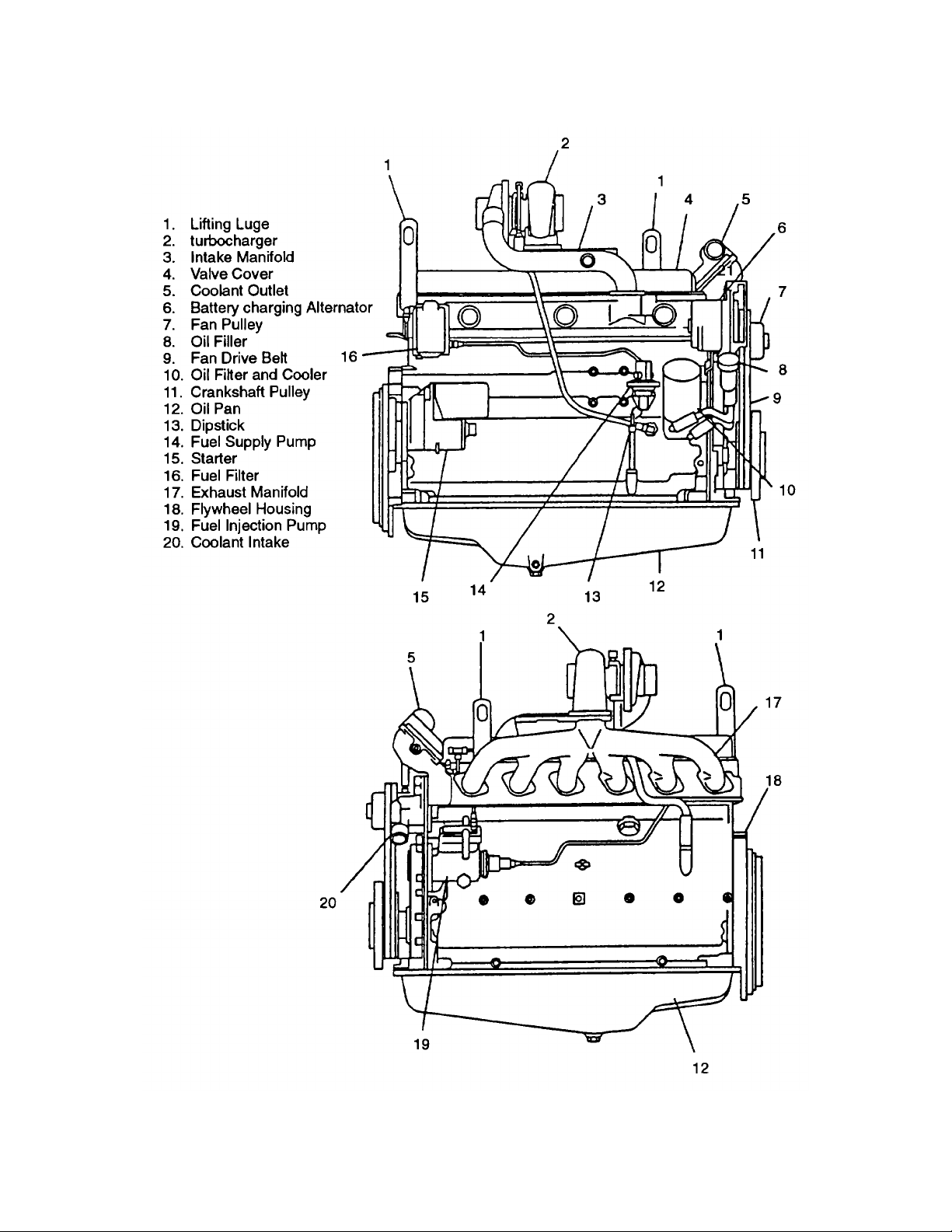
The diesel engine (FIGURE 1-1) is four cylinder, four cycle, fuel injected, turbocharged, and liquid cooled. The firing
order is 1-5-3-6-2-4. The number one cylinder is toward the fan end of the engine. The serial number is found on right
side of the cylinder block In the vicinity of the starter. Rotation of engine is counterclockwise as viewed from flywheel.
1-1

ARMY TM 9-2815-256-24
AIR FORCE TO 38G1-96-2
MARINE CORPS TM 2815-24/5
NOTE
All locations referenced herein are given facing the flywheel end (rear) of the engine.
1-8. DETAILED DESCRIPTION.
1-8.1. Turbocharger. A turbocharger, operated by exhaust gases, compresses intake air and routes it to the combustion
chamber.
1-8.2. Camshaft. The camshaft is driven by an intermediate gear in the timing gear train which meshes with the
crankshaft gear. Camshaft rotates in honed machined bores in cylinder block; no bushings are used. The camshaft
lobes determine the time and rate of opening of each valve and actuates the fuel supply pump.
1-8.3. Intake and Exhaust Valves. Intake and exhaust valves are operated by cam followers, push rods, and rocker arm
assembly. Valve seat inserts in cylinder head are used for intake and exhaust valves.
1-8.4. Crankshaft. The crankshaft is a one-piece, heat treated, steel forging which operates in replaceable two-piece
front and center main bearings and five-piece rear main bearing. The rear thrust bearing has a five-piece set to support
crankshaft thrust and to limit end play.
1-8.5. Cylinder Liners and Pistons. Cylinder liners are "wet" (surrounded by coolant) and are individually replaceable.
O-rings are used to seal the connection between cylinder block and liners. Pistons are made of cast high-grade
aluminum alloy with internal ribbing. The skirt is cam ground to allow for expansion when heated during operation. The
piston crown has a cut-out swivel cup with a truncated cone in the center. Two compression rings and one oil control ring
are used. The top compression ring is a keystone type ring. All piston rings are located above the piston pin. The
hardened piston pins are fully-floating and held in position by means of retainer rings. Spray jets (piston cooling orifices)
in cylinder block direct pressurized oil to lubricate piston pins and cool pistons. Connecting rods are of forged steel and
have replaceable bushing and bearing inserts.
1-8.6. Cooling System. The cooling system consists of a radiator, water pump, cooling fan, two thermostats, and
connecting hoses. The fan is mounted on shaft of water pump and both are belt driven from the crankshaft pulley. The
thermostats control engine temperature and are installed in top of engine. The function of the cooling system is to
maintain a specific operating temperature of 175 to 185°F (79 to 85°C) for the engine.
1-8.7. Lubrication System. The lubrication system consists of oil pan (sump), a gear type pump, full flow spin-on oil filter
with built-in bypass valve, oil cooler with built-in bypass valve, pressure regulating valve, bypass valve, and the internal
passages.
1-8.8. Fuel System. The function of the fuel system is to inject a metered quantity of clean atomized fuel into the engine
cylinders at a precise time near the end of the compression stroke of each piston. The fuel system consists of the fuel
tank, fuel filter/water separator, fuel supply pump, fuel injection pump, and the fuel injectors. The fuel tank is not
mounted on the engine. The fuel supply pump is mounted to the block and is driven by the camshaft. The fuel injection
pump is mounted on the front plate and is driven by an intermediate gear in the timing gear train meshing with crankshaft
gear.
1-8.9. Electrical System. The electrical system is 24 VDC operation and consists of a battery charging alternator,
starter, externally mounted batteries, and other items as required. The battery charging alternator is mounted on front of
engine and is belt driven. When engine is operating, the battery charging alternator supplies 24 VDC to recharge the
batteries and maintain them at a full state of charge. The starter is mounted on the flywheel housing and when
energized, engages the ring gear of the flywheel to rotate the engine.
1-2
ARMY TM 9-2815-256-24
AIR FORCE TO 38G1-96-2
MARINE CORPS TM 2815-24/5
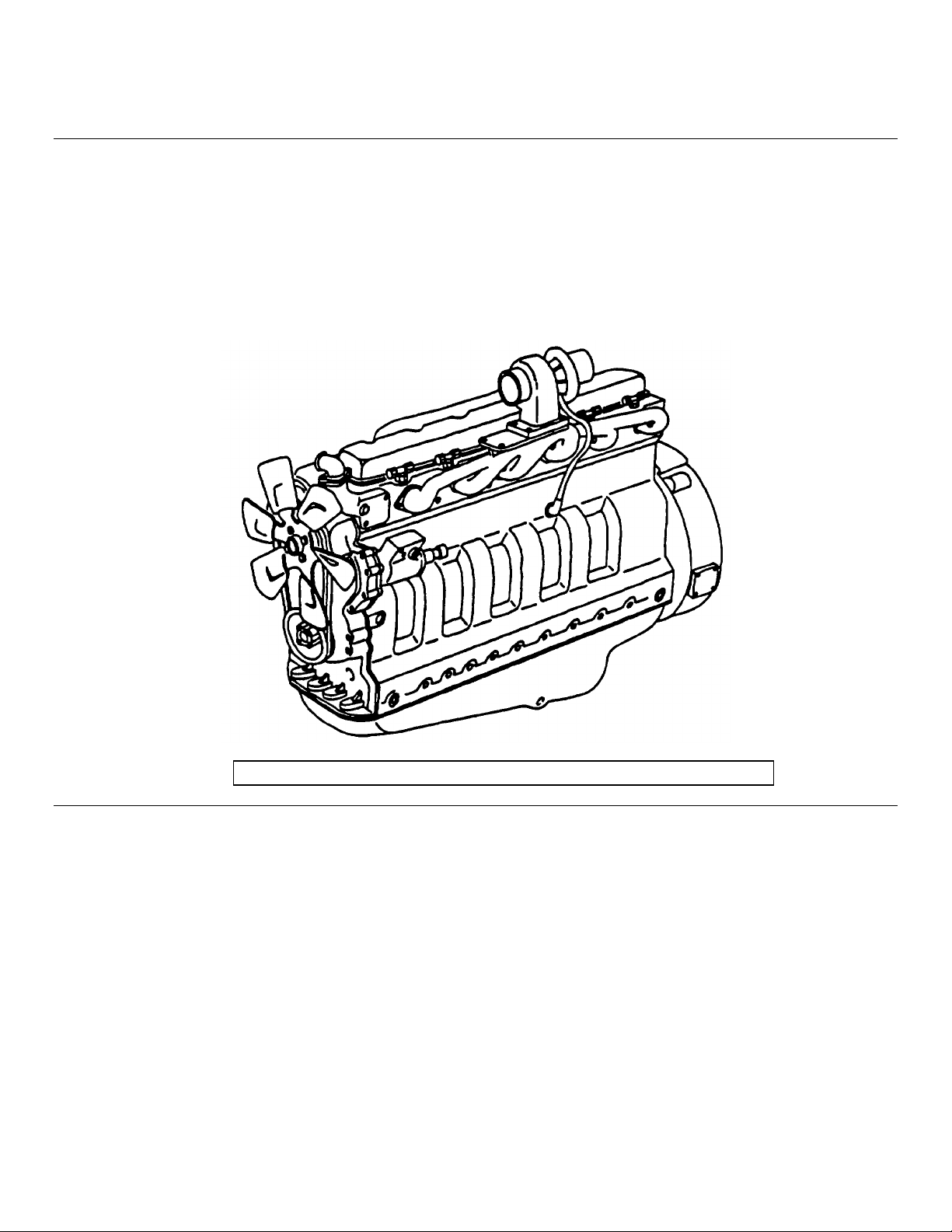
FIGURE 1-1. Engine Components
1-3

1-9. EQUIPMENT DATA.
1-9.1. Leading Particulars. For a list of Leading Particulars, refer to TABLE 1-1.
TABLE 1-1. Table of Specifications
Model...............................................................................................................John Deere 6059T
Type..........................................................................Six cylinder, four cycle, turbocharged diesel
Bore..............................................................................................................4.19 in. (106.5 mm)
Stroke ...........................................................................................................4.33 in. (110.0 mm)
Displacement ...............................................................................................359 cu in. (5.9 liters)
Compression Ratio..............................................................................................................17.8:1
Firing Order.................................................................................................................1-5 3-6-2-4
Width ...............................................................................................................20.4 in. (519 mm)
Height ............................................................................................................40.7 in. (1034 mm)
Length............................................................................................................44.0 in. (1118 mm)
Weight ...............................................................................................................1040 lbs (472 kg)
Injection Pump/Governor............................................................................Stanadyne Model DB2
Injection Starting Pressure
New..............................................................................3650-3750 psi (25,167 - 25,856 kPa)
Used............................................................................................3000 psi (20,685 kPa) Min.
Cylinder Compression Pressure............................................................... 350 psi (2400 kPa)
Lubrication System Capacity................................................................................18 qts (17 liters)
Coolant System Capacity (engine only).............................................................11 qts (10.4 liters)
Alternator .......................................................................................Prestolite 24 volt DC - 42 amp
Starter........................................................................................Nippondenso 24 volt DC - 4.5 kw
ARMY TM 92815-256-24
AIR FORCE TO 38G1-96-2
MARINE CORPS TM 281524/5
Section III. PREPARATION FOR USE
1-10. INSPECTING AND SERVICING ENGINE.
This section provides information and guidance for inspecting, servicing, and installing the engine. For additional
information, refer to end item maintenance manual.
1-10.1. Inspection.
a. Check that all packing materials have been removed.
b. Check engine identification plate for positive identification.
c. Inspect engine exterior for shipping damage.
d. Check fan drive belt for proper tension. Refer to end item maintenance manual.
e. Inspect engine for loose or missing mounting hardware, or damaged or missing parts.
1-10.2. Service. Except for servicing the lubrication system all other servicing must be accomplished after engine is
mounted in the end item. Refer to the end item maintenance manual.
1-4

ARMY TM 9-2815-256-24
AIR FORCE TO 38G1-96-2
MARINE CORPS TM 2815-24/5
CHAPTER 2
OPERATION
Section I. PRINCIPLES OF OPERATION
2-1. INTRODUCTION.
This section contains functional descriptions of the engine systems and how they are connected to the end item.
2-2. COOLING SYSTEM.
The cooling system consists of a radiator, hoses, two thermostat, belt driven fan, water pump, and cooling jackets within
the engine. The water pump forces coolant through passages (coolant jackets) in the engine block and oil cooler where
coolant absorbs heat from the engine. When the coolant temperature is below operating temperature, the thermostat is
closed and coolant is bypassed to the water pump inlet. As coolant temperature increases to 180°F (82°C), the
thermostat fully opens, shutting off all bypass flow and providing full flow through the radiator. Air forced through the fins
of the radiator by the fan cools the coolant pumped through the radiator. Items are added to the engine to monitor
coolant temperature and to warn if temperature exceeds a predetermined value.
2-3. LUBRICATION SYSTEM.
The pressure lubrication system consists of a positive displacement gear-driven pump, filter strainer in the suction pipe,
full flow oil filter, oil cooler, oil pressure regulating valve, and oil by-pass valve. Additionally, the oil cooler and oil filter
have their own bypass valve. The pump draws lubrication oil from the crankcase through a strainer and a suction line.
The oil is then pumped through an oil line to the oil cooler, oil filter, and through the main oil gallery of the cylinder block.
From the oil gallery, oil is forwarded under pressure to the main bearings and spray jets to cool the pistons. Drilled crosspassages in the crankshaft distribute oil from the main bearings to connecting rod bearings. Lube oil holes in Nos. 1, 3,
and 5 main bearing oil grooves are provided to direct oil to the camshaft bearings. A drilled passage from the rear
camshaft bearing through the cylinder block and cylinder head supplies lubricating oil to the rocker arm shaft. An oil
passage direct from the main oil gallery provides lubricating oil to the shaft of the turbocharger. Items are added to
monitor oil pressure and to warn/stop engine if pressure drops to a dangerously low value.
2-4. FUEL SYSTEM.
The fuel system consists of an external fuel tank, fuel supply pump, fuel filter/water separator, fuel injection pump, fuel
injectors, and piping. The fuel supply pump draws fuel from the tank and pressurizes it. This pressure permits the fuel to
flow through the fuel filter/water separator and charge the transfer pump of the fuel injection pump. With the fuel
injection pump charged with fuel by the fuel supply pump, the fuel injection pump plungers pressurize the fuel to
approximately 7255 psi (50,000 kPa). Delivery (pressure) lines are used to route this high pressure fuel to the fuel
injection nozzles. Fuel enters the injection nozzle at a pressure which easily overcomes the pressure required to open
the nozzle valve. When the nozzle valve opens, fuel is forced out through the orifices in the nozzle tip and atomizes as
it enters the combustion chamber. The fuel that is not used by the injectors and injection pump is returned to the fuel
tank via an excess fuel return line.
2-5. ELECTRICAL SYSTEM.
The electrical system consists of external mounted batteries, starter, battery charging alternator, and related relays and
switches for control of the system. Battery power supplied to the starter during the start cycle energizes the starter which
engages the ring gear of the flywheel causing the engine to turn over. When engine start is complete the starter is
deenergized and disengages from the flywheel. The battery charging alternator is belt driven. It is a 42 ampere, 24 VDC
alternator that when operating supplies voltage to recharge the batteries and maintain them at a full state of charge.
Section II. OPERATING INSTRUCTIONS
NOTE
Refer to end item operator's manual.
2-1/(2-2 blank)

ARMY TM 9-2815-256-24
AIR FORCE TO 38G1-96-2
MARINE CORPS TM 2815-24/5
CHAPTER 3
MAINTENANCE
Section I. PREVENTIVE MAINTENANCE CHECKS AND SERVICES (PMCS)
3-1. PMCS PROCEDURES.
3-1.1. General.
To ensure that engine is ready for operation at all times, it must be inspected so defects can be discovered and corrected
before they result in serious damage or failure. Perform operator's PMCS prior to or in conjunction with performance of
engine PMCS. For engine PMCS, refer to TABLE 3-1.
Table 3-1. Preventive Maintenance Checks and Services (PMCS)
Item Interval Procedures Check Equipment is
No. Item for and have Not/Ready
M Q S A B H to be repaired or adjusted Available
Inspected as necessary If:
1 • 300 Oil Filter Refer to paragraph
3-16.1.
NOTE
Oil filter change interval
is a hard time replacement to be used when
AOAP lab is not
available.
2 3000 Engine Valve Adjust engine valve
Tappets tappets. Refer to
paragraph 3-32.1.
3 3000 Engine Fuel Remove, clean, and
Injectors test injectors. Refer
to paragraph 3-5.
4 1500 Engine Check engine com- Engine compression
Compression pression. Refer to is low.
paragraph 3-5.
5 1500 Engine Oil Check engine oil Engine oil pressure
Pressure pressure. Refer to not as specified.
paragraph 3-21.4.
Change 3 3-1

ARMY TM 9-2815-256-24
AIR FORCE TO 38G1-96-2
MARINE CORPS TM 2815-24/5
Section II. TROUBLESHOOTING
3-2. TROUBLESHOOTING PROCEDURES.
3-2.1. Purpose of Troubleshooting Table.
This section contains troubleshooting information for locating and correcting operating troubles which may develop in the
engine. Each malfunction for an individual component, unit, or system is followed by a list of tests or inspections which
will help you to determine probable causes and corrective action to take. You should perform tests/inspections and
corrective actions in order listed.
This table cannot list all malfunctions that can occur, nor all tests or inspections and corrective actions. If a malfunction
is not listed or cannot be corrected by listed corrective actions, notify your supervisor.
NOTE
Before you use this table, be sure you have performed your PMCS. Prior to performing
troubleshooting procedures within this manual, perform your operator's troubleshooting and the end
item maintenance manual troubleshooting
SYMPTOM INDEX
Troubleshooting
Malfunction Procedures Page
Engine Will Not Crank 3-4
Starter Operates But Engine Does Not Turn Over 3-5
Engine Hard To Start Or Will Not Start 3-5
Engine Hard To Start Or Will Not Start In Cold Weather. 3-7
Engine Misfires Or Runs Irregularly Or Stalls Frequently 3-7
Engine Does Not Develop Full Power 3-9
Engine Overheating 3-9
Excessive Oil Consumption 3-10
Low Oil Pressure 3-11
Excessive Fuel Consumption 3-13
Black or Gray Smoke 3-14
Blue Exhaust Smoke 3-15
Engine Knocks 3-16
Engine Makes Abnormal Noise 3-17
Engine Makes a Gas Leaking Noise 3-19
Detonation or Pre-Ignition 3-20
Battery Charge Ammeter Shows No Charge When Batteries Are Low 3-20
Battery Charge Ammeter Shows Excessive Charging After Prolonged Period 3-21
3-2

Table 3-2. Troubleshooting
MALFUNCTION
TEST OR INSPECTION
CORRECTIVE ACTION
1. ENGINE WILL NOT CRANK.
Step 1. Check for defective end item starting system.
Troubleshoot per end item maintenance manual. If not defective, do step 2.
Step 2. Check for defective starter solenoid.
a. Listen for audible clink during attempted start. If click is heard, do step 3.
b. Replace defective starter solenoid. Refer to paragraph 3-12.
Step 3. Check for defective starter motor.
Replace defective starter, refer to paragraph 3-12.2.
ARMY TM 9-2815-256-24
AIR FORCE TO 38G1-96-2
MARINE CORPS TM 2815-24/5P
2. STARTER OPFRATES BUT FNGINE DOES NOT TURN OVER.
Step 1. Check for worn or broken starter pinion gear and/or flywheel ring gear.
a. Remove starter and inspect pinion gear and flywheel ring gear for damage. If not defective, do step
2.
b. Replace defective clutch assembly and/or flywheel ring gear. Refer to paragraphs 3-12. and 3-35.
Step 2. Crank shaft rotation restricted.
a. Attempt to manually rotate engine.
b. Repair and/or replace engine as necessary.
3-3

Table 3-2. Troubleshooting - Continued
MALFUNCTION
TEST OR INSPECTION
CORRECTIVE ACTION
3. ENGINE HARD TO START OR WILL NOT START.
Step 1. Check for fuel being supplied to fuel injection pump.
a. Test supply pump capacity. Refer to paragraph 3-25.2. If supply pump not defective, do step 2.
b. Repair or replace fuel supply pump. Refer to paragraph 3-25.
Step 2. Check for clogged fuel filter/water separator.
Replace filter cartridge. Refer to paragraph 3-24.1. if not clogged, do step 3.
Step 3. Check for air in fuel system lines.
Bleed fuel system. Refer to paragraph 3-23. If fuel system is free of air, do step 4.
ARMY TM 9-2815-256-24
AIR FORCE TO 38G1-96-2
MARINE CORPS TM 2815-24/5P
Step 4. Check for fuel injector starting pressure too low or spray condition improper.
a. Remove, clean, and test fuel injector. Refer to paragraphs 3-29.1., 3-29.2., and 3-29.3. if not
defective, do step 5.
b. If defective replace fuel injector. Refer to paragraph 3-29.
Step 5. Check for improper fuel injection pump timing.
a. Check fuel injection pump timing. Refer to paragraph 3-28. If fuel injection pump timing is correct,
do step 6.
b. Adjust fuel injection pump timing. Refer to paragraph 3-28.
Step 6. Check for defective fuel injection pump
a. Test fuel injection pump. Refer to paragraph 3-27.7.
b. Repair or replace defective fuel injection pump. Refer to paragraph 3-27.
3-4

Table 3-2. Troubleshooting - Continued
MALFUNCTION
TEST OR INSPECTION
CORRECTIVE ACTION
4. ENGINE HARD TO START OR WILL NOT START IN COLD WEATHER.
Step 1. Check for faulty cold start system.
a. Refer to end item maintenance manual. If not defective, do step 2.
b. Repair cold start system. Refer to end item maintenance manual.
Step 2. Refer to Malfunction 3, and perform steps 1 thru 6.
5. ENGINE MISFIRES OR RUNS IRRFGULARLY OR STALLS FREQUENTLY.
Step 1. Check for fuel being supplied to fuel injection pump.
a. Test fuel supply pump capacity. Refer to paragraph 3-25.2. If supply pump not defective, do step 2.
ARMY TM 9-2815-256-24
AIR FORCE TO 38G1-96-2
MARINE CORPS TM 2815-24/5P
b. Repair or replace fuel supply pump. Refer to paragraph 3-25.
Step 2. Check for air in fuel system lines.
Bleed fuel system. Refer to paragraph 3-23. If no air, do step 3.
Step 3. Check for low coolant temperature.
a. If coolant temperature not low, do step 4.
b. Replace defective thermostat. Refer to paragraph 3-9.
Step 4. Check for fuel injector nozzle dirty, defective, or leaking.
a. Remove, clean, and test fuel injector. Refer to paragraphs 3-29.1., 3-29.2., and 3-29.3. If not
defective, do step 5.
b. Replace fuel injector nozzle. Refer to paragraph 3-29.
Step 5. Check for improper fuel injection pump timing.
Adjust fuel injection pump timing. Refer to paragraph 3-28. If adjusted properly, do step 6.
3-5

Table 3-2. Troubleshooting - Continued
MALFUNCTION
TEST OR INSPECTION
CORRECTIVE ACTION
Step 6. Check for defective fuel injection pump.
a. Test fuel injection pump. Refer to paragraph 3-27.7. If not defective, do step 7.
b. Replace fuel injection pump. Refer to paragraph 3-27.
Step 7. Check for valves properly adjusted.
Adjust valves. Refer to paragraph 3-32.1. If properly adjusted, do step 8.
Step 8. Check for low engine compression.
a. Perform engine compression check. Refer to paragraph 3-5.
b. If engine defective, repair or replace engine.
ARMY TM 9-2815-256-24
AIR FORCE TO 38G1-96-2
MARINE CORPS TM 2815-24/5P
6. ENGINE DOES NOT DEVELOP FULL POWER.
Step 1. Check for blocked air intake system.
Remove blockage as found. If no blockage is found, do step 2.
Step 2. Check for clogged fuel filter/water separator.
Replace fuel filter cartridge. Refer to paragraph 3-24.1. If not clogged, do step 3.
Step 3. Engine overheated.
If engine overheated, refer to Malfunction 7. if not a problem, refer to Malfunction 5.
7. ENGINE OVERHEATING.
Step 1. Inspect coolant level.
a. Check engine for coolant leaks, If engine has no leaks, do step 2.
b. Repair coolant leaks.
3-6
 Loading...