

Page 1
VX7021
Installation / Quick Start Guide
Complete operation manuals are
online at www.jensenmobile.com
Note: There is no operation manual in this package
What’s in the Box
The following items are supplied
with the VX7021:
• VX7021 Head Unit
• Trim Ring
• Hardware
• Power/Speaker Output Harness
• Remote Control
• External Microphone
• GPS Antenna
• Installation Guide
Tools and Supplies
The following tools and supplies
are needed to install the head unit:
• Torx type, at-head and Philips
screwdrivers
• Wire cutters and strippers
• Tools to remove existing radio (screw
driver, socket wrench set or other
tools)
• Electrical tape
• Crimping tool
• Volt meter/test light
• Crimp connections
• 18 gauge wire for power connections
• 16 – 18 gauge speaker wire
Page 2
Steering Wheel Control (SWC) Ready
The recommended SWC Interface is the PAC SWI-RC steering wheel control adapter.
SWI-RC installation hints:
1. Set "Radio Select Switch". Set the SWI-RC to position 7 - "Pioneer/Sony/Other".
2. Programming - Use the "Other" radio function mapping order for Jensen branded head units.
3. When programming the SWI-RC, if a function is not supported (or not desired), then the function MUST be skipped as per
the PAC SWI-RC instructions.
4. The SWC functions MUST also be programmed in the correct order per the PAC SWI-RC radio function mapping order
instructions.
Disconnect the Battery
• To prevent a short circuit, be sure to turn off the ignition and remove the negative (-) battery cable prior to installation.
the head unit is to be installed in a car equipped with an on-board drive or navigation computer, do not disconnect the
battery cable. If the cable is disconnected, the computer memory may be lost. Under these conditions, use extra
caution during installation to avoid causing a short circuit.
Replacing the Fuse
• When replacing the vehicles radio fuse always use the proper rated replacement fuse. Using a fuse with an improper rating
could damage the unit and cause a fi re.
NOTE: If
ISO-DIN Installation
The head unit is designed to fi t into a 2.0 DIN dashboard opening. The unit has threaded holes in the chassis side panels which may
be used with the original factory mounting brackets of some Toyota, Nissan, Mitsubishi, Isuzu, Hyundai and Honda vehicles to
mount the radio to the dashboard. Please consult with your local car stereo specialty shop for assistance on this type of
installation.
1. Remove the existing factory radio from the dashboard or
center console mounting. Save all hardware and brackets as
they will be used to mount the new radio.
2. Remove the factory mounting brackets and hardware from the
existing radio and attach them to the new radio.
CAUTION! Do not exceed M5 X 6MM screw size. Longer
screws may damage components inside the chassis.
3. Place the radio in front of the dashboard opening so the wiring
can be brought through the dash opening. Follow the
wiring diagram carefully and make certain all connections are
secure and insulated with wire nuts or electrical tape. After
completing the wiring connections, plug the connector into
the mating socket on the rear of the chassis. Turn the unit
ON to confi rm operation (vehicle ignition switch must be
“ON”). If the unit does not operate, re-check all wiring until the
problem is corrected.
4. Mount the new radio assembly to the dashboard or center
console using the reverse procedure in step 1 above.
CAUTION! Be careful not to damage the car wiring.
NOTE: It is the end-users responsibility to install and operate this unit in a manner in accordance with local, state and federal
laws. The PARKING BRAKE wire MUST BE CONNECTED as directed in the manual.
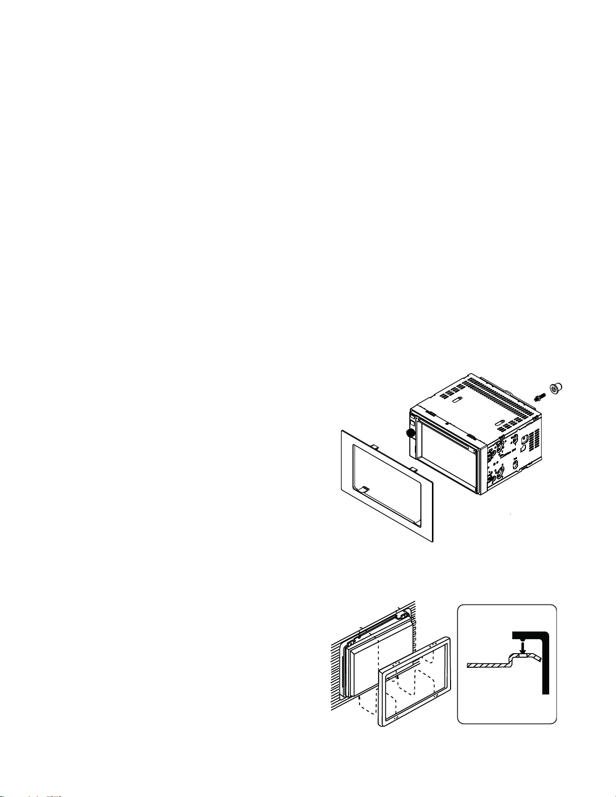
Using the Cosmetic Trim Ring
A cosmetic trim ring is supplied with the head unit for installation
exibility. This unit will t into most import dashes with little or no
modi cation to the dash board/cavity. Some US domestic vehicle
dashes will accept a Double-DIN chassis, but there is usually a
small gap between the radio and dash piece after installation is
complete. In this case, use the trim ring to conceal any gaps that
may be present.
NOTE: For proper operation of the CD/DVD player, the chassis must be mounted within 30° of horizontal. Make sure the
unit is mounted within this limitation.
2
Page 3

Wiring Diagram
CAUTION! IMPORTANT: Incorrect wiring connections can damage the unit. Follow the wiring instructions
carefully, or have the installation handled by an experienced technician.
Need Help? For technical assistance, call the Jensen customer support line at 1-888-921-4088.
Note: Some vehicles may not support all SWC functions. Professional Installation is recommended.
Yellow RCA - Rear Camera In
Black DIN Cable - SiriusXM
Black Female 3.5mm - BT Microphone
SWC
GREEN/WHITE
REVERSE (+)
3.5mm FEMALE CONN.
PINK
BLUE
ORANGE
TFT DIMMER (+)
POWER ANTENNA / AMP (+)
PARKING BRAKE (-)
RED
ACC / IGNITION (+)
BLACK
YELLOW
BATTERY 12V (+)
GROUND (-)
GRAY/BLACK
GREEN/BLACK
GREEN
PURPLE/BLACK
PURPLE
RIGHT REAR SPEAKER (+)
RIGHT REAR SPEAKER (-)
LEFT REAR SPEAKER (+)
LEFT REAR SPEAKER (-)
RIGHT FRONT SPEAKER (-)
GRAY
WHITE/BLACK
WHITE
LEFT FRONT SPEAKER (-)
LEFT FRONT SPEAKER (+)
RIGHT FRONT SPEAKER (+)
Black 1mm Wire - BT Antenna
3
Page 4

Limited One Year Warranty
This warranty gives you specific legal rights. You
may also have other rights which vary from
state to state.
Dual Electronics Corp. warrants this product to the
original purchaser to be free from defects in
material and workmanship for a period of one year
from the date of the original purchase.
Dual Electronics Corp. agrees, at our option, during
the warranty period, to repair any defect in
material or workmanship or to furnish an equal
new, renewed or comparable product (whichever
is deemed necessary) in exchange without
charges, subject to verification of the defect or
malfunction and proof
of the date of purchase. Subsequent replacement
products are warranted for the balance of the
original warranty period.
Who is covered? This warranty is extended to the
original retail purchaser for products purchased
from an authorized Jensen dealer and used in the
U.S.A.
What to do?
1. Before you call for service, check the
troubleshooting guide in your owner’s manual.
A slight adjustment of any custom controls
may save you a service call.
2. If you require service during the warranty
period, you must carefully pack the product
(preferably in the original package) and ship it
by prepaid transportation with a copy of the
original receipt from the retailer to an
authorized service center.
3. Please describe your problem in writing and
include your name, a return UPS shipping
address (P.O. Box not acceptable), and a
daytime phone number with your shipment.
4. For more information and for the location of
the nearest authorized service center please
contact us by one of the following methods:
• Call us toll-free at 1-888-921-4088
• E-mail us at cs@.dualav.com
What is covered? This warranty covers all defects
in material and workmanship in this product. The
following are not covered: software, installation/
removal costs, damage resulting from accident,
misuse, abuse, neglect, product modification,
improper installation, incorrect line voltage,
unauthorized repair or failure to follow instructions
supplied with the product, or damage occurring
during return shipment of the product. Specific
license conditions and copyright notices for the
software can be found via www.jensenmobile.com.
Dual Electronics Corporation
Heathrow, FL 32746
Technical Assistance: 888-921-4088
www.jensenmobile.com
© 2016
Printed in China
Exclusion of Certain Damages: This warranty is
exclusive and in lieu of any and all other
warranties, expressed or implied, including
without limitation the implied warranties of
merchantability and fitness for a particular
purpose and any obligation, liability, right, claim
or remedy in contract or tort, whether or not
arising from the company’s negligence, actual or
imputed. No person or representative is
authorized to assume, for the company, any
other liability in connection with the sale of this
product. In no event shall the company be liable
for indirect, incidental or consequential
damages.
 Loading...