


MM 14D
LOW NOISE PROFESSIONAL PA-MIXER
Operation Manual EN
Mode d'emploi FR
Gebruiksaanwijzing NL
Bedienungsanleitung DU
Manual de instrucciones ES
Manual do utilizador PT
WWW.BEGLEC.COM
Copyright © 2008 by BEGLEC cva.
Reproduction or publication of the content in any manner, without express permission of the publisher, is prohibited. |
Version: 1.0 |
The Power Source for DJ’s |

EN - DISPOSAL OF THE DEVICE
Dispose of the unit and used batteries in an environment friendly manner according to your country regulations.
FR - DÉCLASSER L’APPAREIL
Débarrassez-vous de l’appareil et des piles usagées de manière écologique Conformément aux dispositions légales de votre pays.
NL - VERWIJDEREN VAN HET APPARAAT
Verwijder het toestel en de gebruikte batterijen op een milieuvriendelijke manier conform de in uw land geldende voorschriften.
DU - ENTSORGUNG DES GERÄTS
Entsorgen Sie das Gerät und die Batterien auf umweltfreundliche Art und Weise gemäß den Vorschriften Ihres Landes.
ES - DESHACERSE DEL APARATO
Reciclar el aparato y pilas usadas de forma ecologica conforme a las disposiciones legales de su pais.
PT - COMO DESFAZER-SE DA UNIDADE
Tente reciclar a unidade e as pilhas usadas respeitando o ambiente e em conformidade com as normas vigentes no seu país.
ENGLISH |
|
|
|
|
|
|
OPERATION MANUAL |
|
|
|
|
|
|
|
|
|
|
|
|
|
|
|
|
|
|
|
Thank you for buying this JB Systems® product. To take full advantage of all possibilities, please read these operating instructions very carefully.
FEATURES
This unit is radio-interference suppressed. This appliance meets the requirements of the current European and national guidelines. Conformity has been established and the relevant statements and documents have been deposited by the manufacturer.
P.A. mixer with 14 inputs, perfect for microphone mixing or small bands
8 internal DSP-effects (reverb, echo, chorus, flanger, …) with foot switch.
Internal DSP-effects are switched off when the aux1-output is connected.
All input channels have:
o Gain control
o Hi, Mid, Low tone controls
oAux1/internal effect (post fader)
oAux2 (switchable pre/post fader)
oPan/balance control
oPFL switch
oChannel ON/OFF switch
6 mono channels also have:
oBalanced line input (Jack)
oBalanced microphone (XLR)
o48V Phantom power supply
oInserts ( for external effect equipment)
oSelectable 75Hz low cut filter
oClip indicator
4 stereo channels also have:
oBalanced line input (2 jacks: left+right)
oMono/stereo switch (mono: L input to L+R)
Aux send/return masters
Extra stereo RCA tape deck input/output with tape monitor
Balanced left and right master output
.
BEFORE USE
Before you start using this unit, please check if there’s no transportation damage. Should there be any, do not use the device and consult your dealer first.
Important: This device left our factory in perfect condition and well packaged. It is absolutely necessary for the user to strictly follow the safety instructions and warnings in this user manual. Any damage caused by mishandling is not subject to warranty. The dealer will not accept responsibility for any resulting defects or problems caused by disregarding this user manual.
Keep this booklet in a safe place for future consultation. If you sell the fixture, be sure to add this user manual.
To protect the environment, please try to recycle the packing material as much as possible.
Check the contents:
Check that the carton contains the following items:
User manual
MM-14D unit
Power Supply
ENGLISH OPERATION MANUAL
SAFETY INSTRUCTIONS:
CAUTION |
CAUTION: To reduce the risk of electric shock, do not |
|
remove the top cover. No user-serviceable parts inside. |
|
|
|
Refer servicing to qualified service personnel only. |
|
|
The lightning flash with arrowhead symbol within the equilateral triangle is intended to alert the use or the presence of un-insulated “dangerous voltage” within the product’s enclosure that may be of sufficient magnitude to constitute a risk of electric shock.
The exclamation point within the equilateral triangle is intended to alert the user to the presence of important operation and maintenance (servicing) instructions in the literature accompanying this appliance.
This symbol means: indoor use only
This symbol means: Read instructions
This symbol means: Safety Class II appliance
To prevent fire or shock hazard, do not expose this appliance to rain or moisture.
To avoid condensation to be formed inside, allow the unit to adapt to the surrounding temperatures when bringing it into a warm room after transport. Condense sometimes prevents the unit from working at full performance or may even cause damages.
This unit is for indoor use only.
Don’t place metal objects or spill liquid inside the unit. No objects filled with liquids, such as vases, shall be placed on this appliance. Electric shock or malfunction may result. If a foreign object enters the unit, immediately disconnect the mains power.
No naked flame sources, such as lighted candles, should be placed on the appliance.
Don’t cover any ventilation openings as this may result in overheating.
Prevent use in dusty environments and clean the unit regularly.
Keep the unit away from children.
Inexperienced persons should not operate this device.
Maximum save ambient temperature is 40°C. Don’t use this unit at higher ambient temperatures.
Always unplug the unit when it is not used for a longer time or before you start servicing.
The electrical installation should be carried out by qualified personal only, according to the regulations for electrical and mechanical safety in your country.
Check that the available voltage is not higher than the one stated on the rear panel of the unit.
The socket inlet shall remain operable for disconnection from the mains.
The power cord should always be in perfect condition. Switch the unit immediately off when the power cord is squashed or damaged. It must be replaced by the manufacturer, its service agent or similarly qualified persons in order to avoid a hazard.
Never let the power-cord come into contact with other cables!
In order to avoid a hazard, the unit shall only be used with the AC-adaptor delivered with it. If the ACadaptor is damaged, a same model adaptor shall be used only.
When the power switch is in OFF position, this unit is not completely disconnected from the mains!
In order to prevent electric shock, do not open the cover. There are no user serviceable parts inside.
Never repair a fuse or bypass the fuse holder. Always replace a damaged fuse with a fuse of the same type and electrical specifications!
In the event of serious operating problems, stop using the appliance and contact your dealer immediately.
Please use the original packing when the device is to be transported.
Due to safety reasons it is prohibited to make unauthorized modifications to the unit.
INSTALLATION GUIDELINES:
Install the unit in a well-ventilated location where it will not be exposed to high temperatures or humidity.
Placing and using the unit for long periods near heat-generating sources such as amplifiers, spotlights, etc. will affect its performance and may even damage the unit.
The unit can be mounted in 19-inch racks. Attach the unit using the 4 screw holes on the front panel. Be sure to use screws of the appropriate size. (screws not provided)
Take care to minimize shocks and vibrations during transport.
JB SYSTEMS® |
1/44 |
MM-14D |
JB SYSTEMS® |
2/44 |
MM-14D |

ENGLISH |
OPERATION MANUAL |
When installed in a booth or flight case, please make sure to have good ventilation to improve heat evacuation of the unit.
To avoid condensation to be formed inside, allow the unit to adapt to the surrounding temperatures when bringing it into a warm room after transport. Condense sometimes prevents the unit from working at full performance.
CLEANING THE APPLIANCE:
Clean by wiping with a polished cloth slightly dipped with water. Avoid getting water inside the unit. Do not use volatile liquids such as benzene or thinner which will damage the unit.
CONNECTIONS
For more information on connections, please refer to the next chapter.
Be sure to turn off the mixer before you make changes to the different connections.
In this manual we talk about “line inputs”. This is a global name for inputs with a level between 750mV and 2V. This includes tuners, videos, CD-players, etc.
FUNCTIONS
INPUT CHANNELS
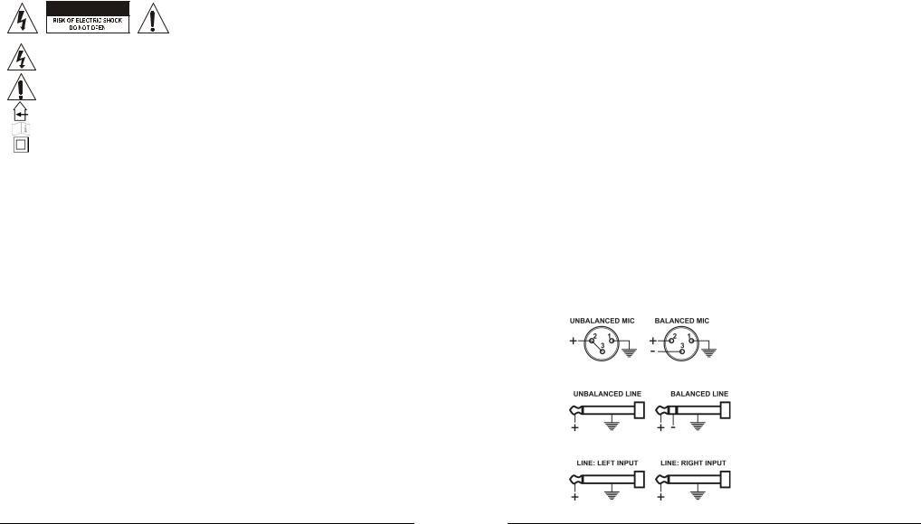
1.COMBO INPUT:
MICROPHONE INPUT = 3 PIN FEMALE XLR CONNECTOR
MONO LINE INPUT = 1/4" JACK SOCKET
2.1/4" JACK SOCKET LINE INPUTS
3.INSERT
Allows you to insert an external effect (like compressor, noise gate, equaliser, etc) that you will only use for this channel. Wiring ¼” Stereo Jack socket:
4. LOW CUT FILTER Switch
When this button is lit, the frequencies below 75Hz for this channel will be filtered. This can be usefull for example to avoid ‘popping’ of microphones or stage rumble.
5. STEREO / MONO SWITCH
When this button is lit, the mono function is activated; the Left input signal will be send to the Left and Right channel
ENGLISH |
OPERATION MANUAL |
|
6. |
CLIP LED |
|
|
This warning will illuminate 4dB before clipping and will remain on for a short period. For optimal |
|
|
input channel running level, adjust Gain Control until Clip indicator illuminates while signal peaks are |
|
|
present. Then |
|
|
adjust the gain setting until Clip indicator is off. This will give optimal signal to noise. |
|
7. |
GAIN CONTROL |
|
|
Allows maximum input signal control and will accommodate most microphones of both low or high |
|
|
impedance to 600 Ohm as well as Phantom Power (48 Volt) types. The line input can be anything |
|
|
from keyboard through to line level feeds from other equipment. |
|
|
Gain range: |
|
|
XLR input +15 to +60dB |
|
|
Jack input –15 to +30dB |
|
8. |
EQ CONTROL ‘HIGH’ |
|
|
Allows 15dB cut/boost for the high frequencies (15kHz) |
|
9. |
EQ CONTROL ‘MID’ |
|
Allows 15dB cut/boost for the mid frequencies (2,5kHz)
10. EQ CONTROL ‘LOW’
Allows 15dB cut/boost for the low frequencies (65Hz)
11. AUX SEND 1 (Post-Fade)
This auxiliary send control is ‘Post-fade’ and is mainly used to send the signal of the channel to the internal effect module. When the AUX1/FX send (11) is used, the internal effect unit is switched off. The AUX1 send level changes with the position of the channel fader (17).
12. AUX SEND 2 (Pre-Fade or Post-Fade)
This knob is used to send the audio signal of this channel to the AUX 2 SEND output. It can be switched pre or post fader. See next point (13) for more information
13.PRE-FADE / POST-FADE SWITCH for AUX SEND 2
Button is lit: AUX2 for this channel is switched PREFADE. The level is only influenced by the Gain control (7) and not by the channel fader (17). Use this setting for example when AUX2 is used to control stage monitors.
Button is not lit: AUX2 for this channel is switched POST-FADE. The level is also influenced by the position of the channel fader (17). Use this setting for example when AUX2 is used for external effect equipment.
14.PAN / BAL CONTROL
Pan control: also called “panoramic control“ is used on the mono input channels to position the mono microphone somewhere left or right in the stereo output.
Balance control: is used to set the stereo balance of the stereo input channels.
15.PFL SWITCH
Also called “Pre Fade Listening” is used to monitor the input channel on the headphone while the channel fader is closed.
16. CHANNEL ON / OFF BUTTON
This button is very usefull if you want to cut the output of an input channel without changing the settings and levels. Switching off unused channels increases the signal/noise ratio of the mixer.
ON button is lit: The channel is switched on
ON button is not lit: the channel is switched off
17.60mm FADER
Controls the output signal of the corresponding input channel.
JB SYSTEMS® |
3/44 |
MM-14D |
JB SYSTEMS® |
4/44 |
MM-14D |

ENGLISH |
OPERATION MANUAL |
OUTPUT SECTION
1. AUX1 RETURN– 1/4" Jack Mono Socket Inputs
To inject the return signal from external effects back into the mixing console. When a jack is inserted, the internal DSP-effects are not used.
2. AUX2 RETURN– 1/4" Jack Mono Socket Input
Same function as Aux1 Return(1). Can also be used to connect an extra sound source (ex. CD player) to the mixing console.
3. POWER LED
This blue led is lit when the power is switched on. (the power switch is situated on the back of the mixing console)
4. LED VU-METER
This is a 12 segment led meter with VU calibration providing a signal monitor range from –20dB to 6dB. with a change of colour at the nominal 0dB position.
5. MASTER CONTROL FOR AUX1 SENDS
Used to set the general output level of the AUX1-signals, controlled by the AUX1 FX Sends (11) and sent to the internal or external effect processor.
6. MASTER CONTROL FOR AUX2 SENDS
Used to set the general output level of the AUX2-signals, controlled by the AUX2 FX Sends (12) and sent to the external effect processor (post-fade) or to stage monitors (pre-fade).
7. MASTER CONTROL FOR AUX1 RETURN
Used to mix the AUX1 return signal with the main output of the mixing console.
8. MASTER CONTROL FOR AUX2 RETURN
Used to mix the AUX2 return signal with the main output of the mixing console.
9. MASTER OUTPUT FADER CONTROL
Used to set the required overall output level to the power amplifier (or other equipment). The calibration shows a suggested nominal running level, referenced ‘0’ (10dB boost is available if required).
10. STEREO MAIN MIX OUTPUT - 3 pin Male XLR Sockets
Used to connect the master output (Main mix) of the mixer to a power amplifier (or other equipment)
Output wiring:
11. AUX SEND OUTPUT – 1/4" Jack Mono Socket (unbalanced) output
Used to send the signal of AUX1 to external equipment or effect units.
Remark: When you insert a jack connector in the AUX1 SEND output, the internal effect unit will automatically be deactivated.
Output wiring:
ENGLISH |
OPERATION MANUAL |
12.AUX SEND OUTPUT – 1/4" Jack Mono Socket (unbalanced) output
Used to send the signal of AUX2 to external equipment, effect units or stage monitors.
13.TAPE OUT – stereo RCA Socket Outputs (unbalanced)
The signal is derived from the main stereo output mix after the output faders and can be used to record the master mix.
14. TAPE IN – stereo RCA Socket Inputs (unbalanced)
Signal is routed to the main stereo output before the faders and the monitoring system.
15. TAPE MONITOR SWITCH
Used to select which signal is routed to the PFL-switch (16):
Switch ON (lit): signal from TAPE IN (14)
Switch OFF (not lit): signal from MAIN MIX. This is the same signal as on the TAPE OUT (13) and the MAIN MIX OUTPUT(10).
16.PFL SWITCH
Used to select which signal is routed to the HEADPHONE output (19):
Switch ON (lit): PFL-signals of the input channels.
Switch OFF (not lit): signal is selected by the TAPE MONITORswitch(15).
17.PLAYBACK SWITCH
Used to add the stereo TAPE IN(14) signal to the main stereo output mix or not.
18. PLAYBACK LEVEL CONTROL
Used to set the playback level of the TAPE IN(14) signal.
19. HEADPHONE OUTPUT – 1/4" Stereo Jack Socket Output
Output wiring:
Minimum Load impedance: 40 Ohm
20. HEADPHONE LEVEL CONTROL
Sets the level of the HEADPHONE output (19).
21. DSP CLIP LED
This led blinks when the input signal of the internal DSP-effect processor is too high.
22. EFFECT SELECTOR KNOB
Used to select one of the 8 available digital effects.
23. DSP TIMING KNOB
Used to adapt the selected effect to your personal taste.
24. DSP MUTE
When this button is lit, the internal effect unit is switched off. This is very usefull to compare your mix with and without effects.
25. FOOT SWITCH connector
Here you can connect a foot switch to switch the internal effects on/off. Connector wiring:
JB SYSTEMS® |
5/44 |
MM-14D |
JB SYSTEMS® |
6/44 |
MM-14D |
ENGLISH |
OPERATION MANUAL |
|
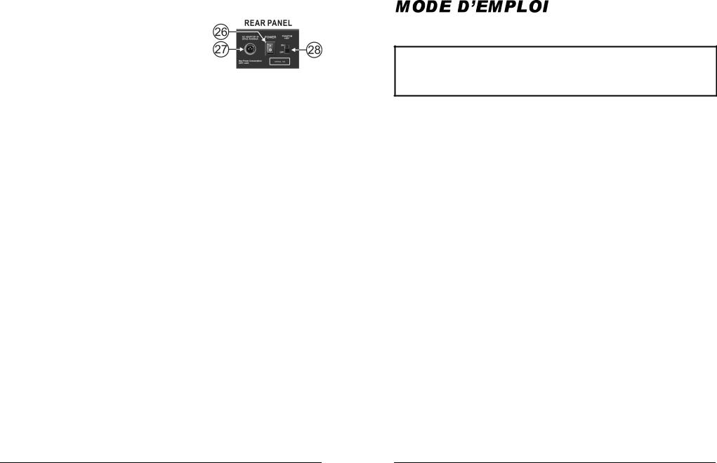
REAR PANEL |
|
|
26. |
POWER ON/OFF SWITCH |
|
|
Used to switch the mixer on/off. We strongly advise to set the master output faders (9) of the mixer |
|
|
and the gain controls of your amplifier to zero before you |
|
|
switch the mixer on or off. |
|
27. |
POWER SUPPLY CONNECTOR |
|
|
Connect the included power supply here. Replace this power |
|
|
supply only with exactly the same type number. |
|
28. |
PHANTOM POWER SWITCH |
|
This +48Vdc voltage should be used when condenser microphones are connected to the microphone inputs.
Attention:
All XLR microphone inputs will carry the 48Vdc voltage when the phantom power is switched on. We strongly advice to check the user manual of the microphones before using the phantom power option.
Make sure to switch the mixer off while using the phantom power switch(28)
Normally you can still connect dynamic microphones while the phantom power is switched on, however to prevent unwanted damage we strongly insist you check the user manual of your dynamic microphone before using it.
SPECIFICATIONS
Power Supply: |
input: |
230Vac, 50Hz |
|
|
output: |
2x 20Vac 500mA |
|
Frequency response: |
microphone: |
20-20.000Hz +/-2dB |
|
|
line input: |
20-20.000Hz +/-1.5dB |
|
THD + noise: |
microphone: |
<0.3% @ 1kHz, 0dB |
|
|
line input: |
<0.05% @ 1kHz, 0dB |
|
Tone controls: |
high freq. |
+/-15dB 15kHz |
|
|
mid freq. |
|
+/-15dB 2,5kHz |
|
low freq. |
|
+/-15dB 65Hz |
S/N Ratio (IHF-A): |
> 85dB |
|
|
Phantom power: |
+48Vdc |
|
|
Micro inputs: |
1mV |
@ 200-600 Ohm/balanced |
|
Line inputs: |
300mV |
@ 10kΩ |
|
Record output: |
775mV |
@ 50kΩ |
|
Master output: |
2V |
@ 600Ω |
|
Dimensions: |
483(W) x 355(H) x 78(D) mm |
||
Weight (mixer): |
5,4kg |
|
|
Weight (power adapter): |
0,85kg |
|
|
Every information is subject to change without prior notice
You can download the latest version of this user manual on our website: www.beglec.com
FRANCAIS |
|
MODE D’EMPLOI |
|
|
|
|
|
|
Nous vous remercions d’avoir acheté ce produit JB Systems®. Veuillez lire ce mode d’emploi très attentivement afin de pouvoir exploiter toutes les possibilités de cet appareil.
EN VOUS INSCRIVANT POUR LA LETTRE D’INFORMATION VOUS SEREZ TOUJOURS TENU AU COURANT DES DERNIERES NOUVELLES CONCERNANT NOS PRODUITS:
NOUVEAUTES, ACTIONS SPECIALES,JOURNEES PORTES OUVERTES, ETC.
SURFEZ SUR: WWW.BEGLEC.COM
CARACTERISTIQUES
Cet appareil ne produit pas d’interférences radio. Il répond aux exigences nationales et européennes. La conformité a été établie et les déclarations et documents correspondants ont été déposés par le fabricant.
Table de mixage pour sonorisation à 14 entrées, parfaite pour mixer plusieurs micros ou sonoriser un petit orchestre.
8 effets DSP à bord (réverbe, écho, chorus, flanger, …) avec commande par interrupteur à pied.
Les effets DSP internes sont mis hors service quand la sortie AUX1 est connectée.
Tous les canaux d'entrées possèdent les contrôles suivants :
o Contrôle de gain
o Contrôles de tonalité pour les aiguës, les médiums et les basses
oAux 1 / effets internes (post fader)
oAux 2 (choix entre pré et post fader)
oContrôle de panoramique / balance
oInverseur PFL
oInterrupteur de mise en ou hors service pour chaque canal
Les 6 canaux mono possèdent également les caractéristiques suivantes :
oEntrée ligne symétrique (jack)
o Entrée micro symétrique (XLR) o Alimentation fantôme de 48 volts
o Boucles d'insertion (pour ajouter des effets externes)
oFiltre de coupure débrayable pour les basses fréquences (75 Hz)
oIndicateur d'écrêtage
Les 4 canaux stéréo possèdent également les caractéristiques suivantes :
oEntrée ligne symétrique (2 jacks : gauche et droit)
oInverseur mono / stéréo (mono : le signal d'entrée de gauche est envoyé aux deux canaux, le gauche comme le droit)
Connexions générales d'envoi et de retour (aux)
Entrées et sorties stéréo supplémentaires de type RCA pour enregistrer, avec fonction tape monitor.
Sorties générales symétriques gauche et droite.
AVANT L’UTILISATION
Quelques instructions importantes:
Avant d’utiliser cet appareil, assurez-vous de l’absence de dommages liés au transport. En cas de dommages, n’utilisez pas l’appareil et contactez le vendeur.
Important: Cet appareil a quitté notre usine en parfaite condition et bien emballé. Il est primordial que l’utilisateur suive les instructions de sécurité et avertissements inclus dans ce manuel. La garantie ne s’applique pas en cas de dommage lié à une utilisation incorrecte. Le vendeur ne prend pas la responsabilité des défauts ou de tout problème résultant du fait de n’avoir pas tenu compte des mises en garde de ce manuel.
Conservez ce manuel dans un endroit sûr pour toute consultation future. Si vous vendez l’appareil, assurez-vous d’y joindre ce manuel également.
Afin de protéger l’environnement, merci de recycler les emballages autant que possible.
JB SYSTEMS® |
7/44 |
MM-14D |
JB SYSTEMS® |
8/44 |
MM-14D |
FRANCAIS |
MODE D’EMPLOI |
Vérifiez le contenu:
Vérifiez si l'emballage contient bien les articles suivants :
Mode d'emploi
La console de mixage MM-14D
L’adaptateur d’alimentation CA
INSTRUCTIONS DE SECURITE:
ATTENTION: afin de réduire le risque d’électrocution,
CAUTION n’enlevez jamais le couvercle de l’appareil. Il n’y a aucune pièce à l’intérieur de l’appareil que vous puissiez
remplacer vous-même. Confiez l’entretien uniquement à des techniciens qualifiés.
La flèche dans un triangle met l'utilisateur en garde contre la présence de haute tension sans isolation dans l'appareil, ce qui peut causer un risque d'électrocution.
Un point d'exclamation dans un triangle prévient de la présence d'instructions relatives au fonctionnement et à la maintenance se trouvant dans le manuel fourni avec l'appareil.
Ce symbole signifie: uniquement pour usage à l'intérieur.
Ce symbole signifie : Lire le mode d’emploi.
Ce symbole signifie: appareil construit selon les normes de sécurité classe II
Afin d’éviter tout risque d’incendie ou de décharge électrique, ne pas exposer cet appareil à la pluie ou l’humidité.
Pour éviter la formation de condensation à l’intérieur de l’appareil, patientez quelques minutes pour laisser l’appareil s’adapter à la température ambiante lorsqu’il arrive dans une pièce chauffée après le transport. La condensation empêche l'appareil de fonctionner de manière optimale, et elle peut même causer des dommages.
Cet appareil est destiné à une utilisation à l’intérieur uniquement.
Ne pas insérer d’objet métallique ou renverser de liquide dans l’appareil. Aucun objet contenant un liquide, tels que des vases, ne peut être placé sur cet appareil. Cela risquerait de provoquer une décharge électrique ou un dysfonctionnement. Si un corps étranger est introduit dans l’appareil, déconnectez immédiatement de la source d’alimentation.
Aucune source de flamme nue, telle que des bougies allumées, ne peut être placée sur l'appareil.
Ne pas couvrir les orifices de ventilation, un risque de surchauffe en résulterait.
Ne pas utiliser l'appareil dans un environnement poussiéreux et le nettoyer régulièrement.
Ne pas laisser l'appareil à portée des enfants.
Les personnes non expérimentées ne doivent pas utiliser cet appareil.
La température ambiante maximale d’utilisation de l’appareil est de 45°C. Ne pas l’utiliser au-delà de cette température.
Débranchez toujours l’appareil si vous ne l’utilisez pas de manière prolongée ou avant d’entreprendre des réparations.
Les installations électriques ne peuvent être faites que par du personnel qualifié et conformément aux règlements de sécurité électrique et mécanique en vigueur dans votre pays.
Assurez-vous que la tension d’alimentation de la source d’alimentation de la zone dans laquelle vous vous trouvez ne dépasse pas celle indiquée à l’arrière de l’appareil.
La prise doit toujours être accessible pour que le cordon secteur puisse être enlevé à tout moment.
Le cordon d’alimentation doit toujours être en parfait état. Mettez immédiatement l’unité hors tension si le
cordon devait être écrasé ou endommagé. Pour éviter tout risque de choc électrique, le cordon doit être remplacé par le constructeur, son agent ou un technicien qualifié.
Ne laissez jamais le cordon d’alimentation entrer en contact avec d’autres câbles !
Pour éviter tout risque de choc électrique, cet appareil doit être remplacé uniquement avec l’adaptateur
secteur inclus. Si l’adaptateur est défectueux, il sera utilisé seulement par un modèle identique.
Quand l’interrupteur principal est en position OFF, cet appareil n'est pas complètement isolé du courant 230V !
Utilisez toujours des câbles appropriés et certifiés lorsque vous installez l’appareil.
FRANCAIS |
MODE D’EMPLOI |
Pour éviter toute décharge électrique, ne pas ouvrir l’appareil. Il n’y a pas de pièces pouvant être changées par l’utilisateur à l’intérieur.
Ne jamais réparer ou court-circuiter un fusible. Remplacez systématiquement un fusible endommagé par un fusible de même type et ayant les mêmes spécifications électriques !
En cas de problèmes de fonctionnement sérieux, arrêtez toute utilisation de l’appareil et contactez votre revendeur immédiatement.
Utilisez l’emballage d’origine si l’appareil doit être transporté.
Pour des raisons de sécurité, il est interdit d’apporter une quelconque modification à l’appareil non spécifiquement autorisée par les parties responsables.
CONSEILS D'INSTALLATION:
Installer l'appareil dans un lieu bien aéré, à l'abri de l'humidité et des fortes températures.
Placer et utiliser l'appareil à proximité de sources de chaleur telles que spots, amplis,… pourrait affecter ses performances et même endommager l'appareil.
L'appareil peut être installé dans un rack de 19''. Fixez l'appareil en utilisant les 4 trous pour vis sur la face avant. Assurez-vous d'utiliser des vis aux dimensions adaptées (vis non fournies). Essayez d'éviter les vibrations et les coups lors du transport.
En cas d'installation dans un 'flight case', assurer une bonne ventilation afin d'évacuer la chaleur produite par l'appareil.
Pour résorber la condensation à l'intérieur de l'appareil, le laisser s'adapter à la nouvelle température ambiante après le transport. La condensation peut altérer les performances de l'appareil.
NETTOYAGE:
Nettoyez l’appareil à l’aide d’un chiffon doux, légèrement humide. Evitez d’introduire de l’eau à l’intérieur de l’appareil. N’utilisez pas de produits volatils tels que le benzène ou le 'thinner', qui peuvent endommager l’appareil.
CONNEXIONS
Pour plus d'informations sur les connexions, voyez le chapitre suivant.
Assurez-vous d'éteindre la table de mixage avant d'effectuer les différentes connexions. Dans ce mode d'emploi, il est question d'entrée ligne ou “line inputs”. Il s'agit en fait d'un terme générique pour désigner des entrées avec un niveau compris entre 750mV et 2V. Ceci inclut les lecteurs de CD, tuners, vidéo,…
FONCTIONS
CANAUX D'ENTREE
1.Entrées combinées :
Entrée micro = connecteur XLR femelle à 3 broches
Entrée ligne mono = connecteur jack d'1/4"
2.Entrées ligne dotées d'un connecteur jack d'1/4"
JB SYSTEMS® |
9/44 |
MM-14D |
JB SYSTEMS® |
10/44 |
MM-14D |

FRANCAIS |
MODE D’EMPLOI |
3. Prises d'insertion
Ces prises permettent d'insérer un effet externe (tel qu'un compresseur, un noise gate, une égalisation, etc …) que vous ne désirez utiliser que pour un canal exclusivement. Câblage du connecteur jack stéréo d'1/4" :
4. Interrupteur du filtre de coupure pour les basses fréquences
Quand cette touche est allumée, les fréquences en dessous de 75 Hz de ce canal sont filtrées. Cela peut être utile, par exemple, pour éviter les bruits de 'pop' excessifs des micros ou le bruit de fond d'un podium.
5. Inverseur stéréo / mono
Quand ce bouton est allumé, la fonction mono est activée ; le signal d'entrée de gauche sera envoyé aux deux canaux, le gauche comme le droit.
6. LED indicatrice d'écrêtage
L’indicateur d’écrêtage s’allume 4dB avant le signal maximum et restera allumé pendant une courte période. Pour arriver à un fonctionnement optimal du canal d'entrée, ajustez le contrôle de Gain de sorte que l'indicateur d'écrêtage ne s'allume que lorsque des pics de puissance se présentent. Ensuite, ajustez le contrôle de Gain jusqu'à ce que l'indicateur d'écrêtage reste éteint. Cela vous donnera le meilleur rapport signal sur bruit.
7. Contrôle de GAIN :
Permet de contrôler le signal d'entrée au mieux et d'adapter la plupart des micros de basse ou de haute impédance (jusqu'à 600 Ohms), ainsi que les modèles à alimentation fantôme de 48 volts. L'entrée ligne peut être connectée à n'importe quoi, cela va du clavier à un niveau ligne en provenance d'un autre appareil externe.
Fourchettes de gain :
-entrée XLR : de +15 à +60 dB
-entrée jack : de -15 à +30 dB
8.Contrôle d'égalisation ‘HIGH’
Permet de réduire ou d'augmenter les fréquences aiguës (15 kHz) de 15 dB
9. Contrôle d'égalisation ‘MID’
Permet de réduire ou d'augmenter les fréquences médiums (2,5 kHz) de 15 dB
10. Contrôle d'égalisation ‘LOW’
Permet de réduire ou d'augmenter les fréquences graves (65 Hz) de 15 dB
11. AUX SEND 1 (Post-Fade)
Ce contrôle d'envoi de signal auxiliaire vient après le curseur et est principalement utilisé pour envoyer le signal du canal vers le module d'effets interne. Quand l'AUX1/FX send (11) est utilisé, le module d'effets interne est mis hors service. Le niveau d'envoi de l'AUX1 est tributaire de la position du fader de canal (17).
12. AUX SEND 2 (Pre-Fade ou Post-Fade)
Ce bouton est utilisé pour envoyer le signal audio de ce canal vers la sortie AUX2 SEND. Il peut être placé avant ou après le fader. Veuillez vous référer au point suivant (13) pour de plus amples informations.
13.Inverseur PRE-FADE / POST-FADE pour l'AUX SEND 2
Quand la touche est allumée : L'AUX2 de ce canal est placé avant le curseur. Le niveau est influencé uniquement par le contrôle de Gain (7), et pas par le fader de canal (17). Utilisez cette configuration quand l'AUX2 est utilisé pour contrôler les haut-parleurs qui servent de moniteurs de scène.
FRANCAIS |
MODE D’EMPLOI |
Quand la touche n'est pas allumée : L'AUX2 de ce canal est placé après le curseur. Le niveau d'envoi est aussi tributaire de la position du fader de canal (17). Utilisez cette configuration par exemple quand l'AUX2 est utilisé en combinaison avec des effets externes.
14.Contrôle PAN / BAL
Contrôle PAN : est aussi appelé "contrôle de panoramique" et est utilisé sur les canaux d'entrée mono pour positionner un micro mono quelque part entre la gauche et la droite de la sortie stéréo.
Contrôle de balance: est utilisé pour régler la balance stéréo des canaux d'entrée stéréo.
15.Inverseur PFL
Appelé aussi "Pre Fade Listening", il sert à écouter au casque le canal d'entrée alors que le fader de canal est en position zéro.
16. Touche ON / OFF de canal
Cette touche est très utile quand on désire couper le signal de sortie d'un canal d'entrée sans pour autant en changer les réglages ou les niveaux. Le fait de couper les canaux inutilisés augmente le rapport signal sur bruit de la table de mixage.
Quand la touche ON est allumée : Le canal est en service
Quand la touche ON est éteinte : Le canal est hors service
17.Fader de 60 mm
Le fader contrôle le signal de sortie du canal d'entrée correspondant.
SECTION DES SORTIES
1. AUX1 RETURN – Entrées jacks mono ¼"
Sert à réinjecter le signal de retour des effets externes vers la console de mixage. Lorsqu'un jack y est inséré, les effets DSP internes sont mis hors service.
2. AUX2 RETURN – Entrées jacks mono ¼"
Même fonction que l'Aux1 Return (1). Peut également être utilisé pour connecter une source sonore supplémentaire (ex. : lecteur de CD) à la console de mixage.
3. LED d'alimentation secteur
Cette LED bleue est allumée quand l'appareil est sous tension. (l'interrupteur de mise sous tension est situé à l'arrière de la console de mixage)
4. VU-mètres à LED
Il s'agit de VU-mètres à 12 segments LED qui affichent un signal de contrôle allant de –20 dB à 6 dB.
5. Contrôle SEND MASTER pour l'AUX1
Est utilisé pour régler le niveau général de sortie des signaux AUX1, contrôlé par les AUX1 FX Sends (11) et envoyé vers les processeurs d'effets internes ou externes.
6. Contrôle SEND MASTER pour l'AUX2
Est utilisé pour régler le niveau général de sortie des signaux AUX2, contrôlé par les AUX2 FX Sends (12) et envoyé vers les processeurs d'effets externes (après le fader) ou vers les haut-parleurs qui servent de moniteurs de scène (avant le fader).
7. Contrôle RETURN MASTER pour l'AUX1
Contrôle utilisé pour mélanger le signal de retour de l'AUX1 à la sortie générale de la console de mixage.
8. Contrôle RETURN MASTER pour l'AUX2
Contrôle utilisé pour mélanger le signal de retour de l'AUX2 à la sortie générale de la console de mixage.
JB SYSTEMS® |
11/44 |
MM-14D |
JB SYSTEMS® |
12/44 |
MM-14D |
 Loading...