


LM440G = German ~ LM440F = French
Operation Manual EN Mode d'emploi FR Gebruiksaanwijzing NL Bedienungsanleitung DU Manual de instrucciones ES
Manual do utilizador PT
WWW.BEGLEC.COM
Copyright © 2009 by BEGLEC nv
‘t Hofveld 2c, B-1702 Groot-Bijgaarden, Belgium.
Reproduction or publication of the content in any manner, without express permission of the publisher, is prohibited. |
Version: 1.2 |

EN - DISPOSAL OF THE DEVICE
Dispose of the unit and used batteries in an environment friendly manner according to your country regulations.
FR - DÉCLASSER L’APPAREIL
Débarrassez-vous de l’appareil et des piles usagées de manière écologique Conformément aux dispositions légales de votre pays.
NL - VERWIJDEREN VAN HET APPARAAT
Verwijder het toestel en de gebruikte batterijen op een milieuvriendelijke manier conform de in uw land geldende voorschriften.
DU - ENTSORGUNG DES GERÄTS
Entsorgen Sie das Gerät und die Batterien auf umweltfreundliche Art und Weise gemäß den Vorschriften Ihres Landes.
ES - DESHACERSE DEL APARATO
Reciclar el aparato y pilas usadas de forma ecologica conforme a las disposiciones legales de su pais.
PT - COMO DESFAZER-SE DA UNIDADE
Tente reciclar a unidade e as pilhas usadas respeitando o ambiente e em conformidade com as normas vigentes no seu país.

ENGLISH |
OPERATION MANUAL |
OPERATION MANUAL
Thank you for buying this JB Systems® product. To take full advantage of all possibilities, please read these operating instructions very carefully.
FEATURES
This unit is radio-interference suppressed. This product meets the requirements of the current European and national guidelines. Conformity has been established and the relevant statements and documents have been deposited by the manufacturer.
4 channel DMX light modulator:
LM440G ~ LM440F: equipped with 4 internal dimmer packs and mains socket outputs (4x 1750W/res – max. total load = 3450W) Suitable for both inductive and resistive loads.
LM430: no internal dimmer packs, to be used with external DMX power units.
4 extra switch channels to switch light effects on/off via optional DMX switch pack (ex. SW416)
4 user modes:
Individual manual dimming on all 4 channels (stage lighting)
4 Channel light modulator (high, mid, bass, anti-bass)
9 built-in 4channel chaser programs:
audio controlled (built-in micro or external cinch audio input)
static with user selectable speed on fader
Individual dimmer faders on each channel, each with flash buttons.
Master dimmer with overall flash button
Background level dimmer
Standby switch (blackout)
DMX output for extra dimmerand switch packs:
DMX channels 1-4: dimmer channels
DMX channels 5-8: on/off switch channels
BEFORE USE
Check the contents:
Check that the carton contains the following items:
LM430 with AC-adapter or LM440G ~ LM440F
User manual
Some important instructions:
Before you start using this unit, please check if there’s no transportation damage. Should there be any, do not use the device and consult your dealer first.
Important: This device left our factory in perfect condition and well packaged. It is absolutely necessary for the user to strictly follow the safety instructions and warnings in this user manual. Any damage caused by mishandling is not subject to warranty. The dealer will not accept responsibility for any resulting defects or problems caused by disregarding this user manual.
Keep this booklet in a safe place for future consultation. If you sell the fixture, be sure to add this user manual.
To protect the environment, please try to recycle the packing material as much as possible.
ENGLISH OPERATION MANUAL
SAFETY INSTRUCTIONS:
CAUTION |
CAUTION: To reduce the risk of electric shock, do not remove the top cover. |
|
No user-serviceable parts inside. Refer servicing to qualified service |
personnel only.
The lightning flash with arrowhead symbol within the equilateral triangle is intended to alert the use or the presence of un-insulated “dangerous voltage” within the product’s enclosure that may be of sufficient magnitude to constitute a risk of electric shock.
The exclamation point within the equilateral triangle is intended to alert the user to the presence of important operation and maintenance (servicing) instructions in the literature accompanying this appliance.
This symbol means: Lamp Control Gear
This symbol means: Safety Class II appliance
To prevent fire or shock hazard, do not expose this appliance to rain or moisture.
To avoid condensation to be formed inside, allow the unit to adapt to the surrounding temperatures when bringing it into a warm room after transport. Condense sometimes prevents the unit from working at full performance or may even cause damages.
This unit is for indoor use only.
Don’t place metal objects or spill liquid inside the unit. No objects filled with liquids, such as vases, shall be placed on this appliance. Electric shock or malfunction may result. If a foreign object enters the unit, immediately disconnect the mains power.
No naked flame sources, such as lighted candles, should be placed on the appliance.
Don’t cover any ventilation openings as this may result in overheating.
Prevent use in dusty environments and clean the unit regularly.
Keep the unit away from children.
Inexperienced persons should not operate this device.
Maximum save ambient temperature is 40°C. Don’t use this unit at higher ambient temperatures.
Always unplug the unit when it is not used for a longer time or before you start servicing.
The electrical installation should be carried out by qualified personal only, according to the regulations for electrical and mechanical safety in your country.
Check that the available voltage is not higher than the one stated on the rear panel of the unit.
The socket inlet shall remain operable for disconnection from the mains.
The power cord should always be in perfect condition. Switch the unit immediately off when the power cord is squashed or damaged. It must be replaced by the manufacturer, its service agent or similarly qualified persons in order to avoid a hazard.
Never let the power-cord come into contact with other cables!
In order to avoid a hazard, the unit shall only be used with the AC-adaptor delivered with it. If the ACadaptor is damaged, a same model adaptor shall be used only.
LM440G ~ LM440F must be earthed to in order comply with safety regulations.
In order to prevent electric shock, do not open the cover. Apart from the mains fuse there are no user serviceable parts inside.
Never repair a fuse or bypass the fuse holder. Always replace a damaged fuse with a fuse of the same type and electrical specifications!
In the event of serious operating problems, stop using the appliance and contact your dealer immediately.
Please use the original packing when the device is to be transported.
Due to safety reasons it is prohibited to make unauthorized modifications to the unit.
MAINTENANCE
Clean by wiping with a polished cloth slightly dipped with water. Avoid getting water inside the unit. Do not use volatile liquids such as benzene or thinner which will damage the unit.
JB SYSTEMS® |
1/34 |
LM430 + LM440G ~ LM440F |
JB SYSTEMS® |
2/34 |
LM430 + LM440G ~ LM440F |

ENGLISH |
OPERATION MANUAL |
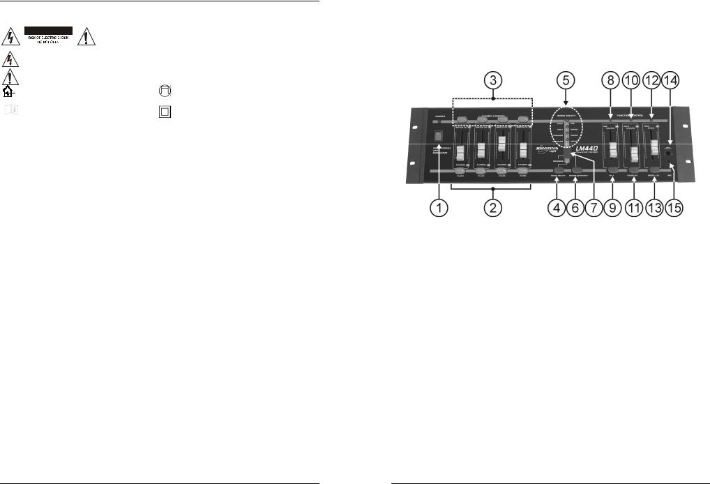
FUNCTIONS (FRONT)
1.POWER SWITCH: used to switch the unit ON/OFF.
2.DIMMER CHANNELS: these are 4 faders used to set the individual dimming levels of the 4 channels. Below each fader there’s a flash button to set the output of the corresponding channel to 100% (full) for as long as the button is pressed. The flash buttons all have backlight so you can easily monitor the output of each channel.
3.SWITCH CHANNELS: these buttons are used to switch 4 individual light effects ON/OFF. To be able to use these buttons you must connect a separate switch pack to the DMX-output of the unit. (DMX address on the switch pack must be set to 005)
4.MODE SELECT: used to select 1 of the 4 user modes:
HOLD DIM: This mode can be used to control the dimming levels of projectors on a small stage. The 4 faders (2) can be used to set the dimming level of each channel individually.
HOLD SOUND: the music is divided into 4 different frequency ranges (bass, middle, high, antibass). Each of the four output channels will respond to a different frequency range.
PROGRAM SOUND: The chaser program selected with the “program select” button (6) will be displayed. The chaser speed is synchronized to the rhythm of the beat.
PROGRAM SPEED: The chaser program selected with the “program select” button (6) will be displayed. The chaser speed can be adapted with the speed fader (12).
5.MODE SELECT INDICATOR: shows which of the 4 modes is currently active.
6.PROGRAM SELECT: When you selected 1 of the 2 program modes (4) then you can use the program select button to choose the program you like. Nine different chaser programs (from 1 to 9) can be selected. Program 0 (zero on the display) is a random program.
7.PROGRAM DISPLAY: shows which chaser program is currently selected.
8.MASTER DIMMER: controls the overall dimming level of the 4 channels.
9.FULL SWITCH: use this button to set the output of the 4 channels to 100% (full) for as long as the button is pressed.
10.BACKGROUND LEVEL: with this fader you can set the background level (minimum output level) of the 4 dimmer channels. This can “soften” the chaser effects so they become less aggressive.
Attention: don’t set this fader to maximum, you will not be able anymore to see the chaser patterns or set proper dimming levels for the 4 individual channels.
11.STANDBY SWITCH: used to cutoff (blackout) the output of the 4 dimmer channels. The 4 switch channels are not affected.
12.PROG SPEED CONTROL: When the “program speed” mode (4) is selected, you can change the speed of the selected chaser program (6) from slow to fast or very fast (13).
13.SPEED x10 BUTTON: Used to multiply/divide by 10 the speed selected with the speed fader (12).
14.AUDIO SENSITIVITY: used to adjust the input sensitivity of the internal microphone or external audio inputs. Adjust the level until the sound activated functions work nicely to the rhythm of the music.
15.INTERNAL MICRO: the internal microphone is installed behind this opening.
ENGLISH |
OPERATION MANUAL |
FUNCTIONS (REAR)
LM430
LM440G ~ LM440F
16.SOUND SOURCE SELECT: used to select which audio input will be used to synchronize the sound related functions:
BUILT-IN MICRO: use this function when the music playback level is high enough so the internal microphone can easily capture the sound. This is the easiest way to use the sound functions.
AUDIO INPUT: use this function when the sound level is rather low. In this case don’t forget to connect the audio input connectors (17)!
17.AUDIO INPUT: when the sound source selector (16) is set to “AUDIO INPUT” you will have to connect these cinch/RCA connectors to an analog audio signal ranging from 200mV to 1000mV. In most cases a record output or secondary master on your mixer will do.
18.DMX OUTPUTS: used to connect the light modulator to DMX power packs. You can use the 5pin XLR or 3pin XLR connectors. Both connectors carry the same signals, they only have a different pinning layout. In most cases however you will use standard XLR-3pin male/female cables. Both the dimmer and switch channels are available on these outputs:
DIMMER CHANNELS: are assigned to DMX addresses 001 to 004. Please set the starting address of the connected dimmer pack to 001.
SWITCH CHANNELS: are assigned to DMX addresses 005 to 008. Please set the starting address of the connected switch pack to 005.
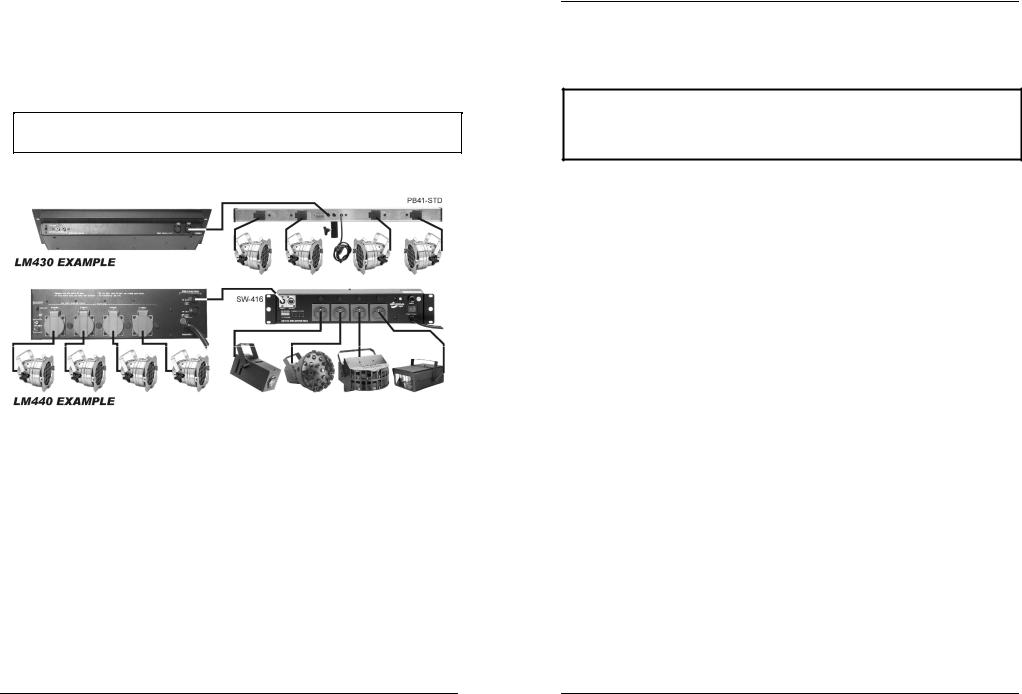
Hint: You can connect all kinds of dimmer/switch packs, however for mobile applications we suggest using the JB Systems® PB41/STD powered DMX-bars. You can easily set each channel in switch or dimmer mode. Moreover you can directly fix your projectors and/or light effects to these powered DMXbars.
19.POWER INPUT: this input depends on the model number of the light modulator:
LM430: low voltage input, connect the supplied AC adapter here. If you should use another adapter, please make sure the output produces 15Vac (>1A) with positive pole (+) in the center of the connector.
JB SYSTEMS® |
3/34 |
LM430 + LM440G ~ LM440F |
JB SYSTEMS® |
4/34 |
LM430 + LM440G ~ LM440F |
ENGLISH |
OPERATION MANUAL |
LM440G ~ LM440F: mains input cable, make sure the local voltage is 230Vac and the projectors are properly connected to the channel output sockets (20) before you connect this cable to the mains wall socket. The maximum total load is 15A or 3450Watts.
20.INPUT FUSE: This is an automatic circuit breaker. When the fuse is blown, first locate and solve the problem that caused the fuse to blow. When the problem is solved, simply push the button to reset the circuit breaker.
21.CHANNEL OUTPUTS: (only on LM440G ~ LM440F) Each channel output has its own output socket to connect any resistive and/or inductive (PAR36) projector(s). Each channel is equipped with a fuse. Always replace a blown fuse with a fuse that has the same characteristics! (250V/8A fast)
VERY IMPORTANT NOTE!
It’s very important to know that the maximum load for each channel is rated at 8A or 1750Watts. However the total load for all 4 channels may not exceed 15A or 3450Watts!
CONNECTIONS
These are just some small examples, many different setups and combinations are possible!
SPECIFICATIONS
LM430: |
|
Power Input: |
AC 15V 1000mA minimum. |
AC Power adapter: |
AC 230V, 50Hz 15Vac / 1000mA (or more) |
DMX outputs: |
3pin XLR + 5pin XLR |
Audio input: |
internal microphone |
|
external audio input on cinch/RCA (200mV 1000mV) |
Size: |
48,3 x 13,2 x 6,0 cm (19”/3U) |
Weight: |
1,9 kg |
LM440G ~ LM440F: |
|
Power Input: |
230Vac / 15A maximum (3450Watts) |
Power outputs: |
4x 230Vac / max. 8A (1750Watts) |
Fuses (size = 6,35 x 32mm): |
channels: 250V/8A (T8AL250V) |
DMX outputs: |
3pin XLR + 5pin XLR |
Audio input: |
internal microphone |
|
external audio input on cinch/RCA (200mV 1000mV) |
Size: |
48,3 x 13,2 x 10,5 cm (19”/3U) |
Weight: |
3,1 kg |
Every information is subject to change without prior notice
You can download the latest version of this user manual on our website: www.beglec.com
FRANCAIS MODE D’EMPLOI
MODE D’EMPLOI
Nous vous remercions d’avoir acheté ce produit JB Systems®. Veuillez lire ce mode d’emploi très attentivement afin de pouvoir exploiter toutes les possibilités de cet appareil.
EN VOUS INSCRIVANT POUR LA LETTRE D’INFORMATION VOUS SEREZ TOUJOURS TENU AU COURANT DES DERNIERES NOUVELLES CONCERNANT NOS PRODUITS:
NOUVEAUTES, ACTIONS SPECIALES, JOURNEES PORTES OUVERTES, ETC.
SURFEZ SUR: WWW.BEGLEC.COM ET INSCRIVEZ VOUS
CARACTERISTIQUES
Cet appareil ne produit pas d’interférences radio. Il répond aux exigences nationales et européennes. La conformité a été établie et les déclarations et documents correspondants ont été déposés par le fabricant.
Modulateur de lumière à 4 canaux DMX :
LM440G ~ LM440F : équipé de 4 gradateurs internes et de 4 prises de sortie (4x 1750W/res – puissance totale maximale = 3450W). Convient aussi bien pour les charges inductives que résistives.
LM430 : ne comporte pas de gradateurs internes, doit être utilisé avec des unités de puissance DMX externes.
4 canaux supplémentaires pour allumer et éteindre les effets de lumière via un switch pack DMX en option (ex. : SW416).
4 modes utilisateur :
Réglage manuel individuel sur chacun des 4 canaux (éclairage de scène)
Modulateur de lumière à 4 canaux (basses, médiums, aiguës, canal négatif)
9 programmes chenillards intégrés à 4 canaux :
contrôlé par source audio (micro intégré ou entrée audio cinch externe)
contrôlé par le curseur de vitesse.
Gradateur individuel (commande par curseur) sur chaque canal, chacun avec bouton flash.
Gradateur général avec bouton flash général.
Gradateur pour niveau d'arrière plan.
Interrupteur temporaire de coupure générale (black out)
Sortie DMX pour blocs de puissance et switch packs supplémentaires :
Canaux DMX 1-4 : canaux commandés par gradateurs.
Canaux DMX 5-8 : canaux commandés par interrupteurs.
AVANT L’UTILISATION
Vérifiez le contenu:
Vérifiez si la boîte contient les articles suivants :
LM430 ou LM440G ~ LM440F avec son adaptateur CA.
Mode d’emploi
Quelques instructions importantes :
Avant d’utiliser cet appareil, assurez-vous de l’absence de dommages liés au transport. Si l’appareil est effectivement endommagé, ne l’utilisez pas et contactez le vendeur.
Important : cet appareil a quitté notre usine en parfaite condition et protégé par un emballage adéquat. Il est primordial que l’utilisateur suive les instructions de sécurité et avertissements inclus dans ce manuel. La garantie ne s’applique pas en cas de dommages liés à une utilisation incorrecte. Le vendeur ne prend pas la responsabilité des dommages ou des problèmes, quels qu'ils soient, s'ils résultent du non respect des mises en garde de ce manuel.
Conservez ce manuel dans un endroit sûr pour toute consultation ultérieure. Si vous vendez l’appareil, assurez-vous d’y joindre ce manuel également.
Afin de protéger l’environnement, merci de recycler les emballages autant que possible.
JB SYSTEMS® |
5/34 |
LM430 + LM440G ~ LM440F |
JB SYSTEMS® |
6/34 |
LM430 + LM440G ~ LM440F |
FRANCAIS MODE D’EMPLOI
INSTRUCTIONS DE SECURITE:
CAUTION |
ATTENTION : afin de réduire le risque d’électrocution, n’enlevez jamais le |
|
couvercle de l’appareil. Il n’y a aucune pièce à l’intérieur de l’appareil que |
|
vous pouvez remplacer vous-même. Confiez l’entretien uniquement à des |
techniciens qualifiés.
La flèche dans un triangle met l'utilisateur en garde contre la présence de haute tension sans isolation dans l'appareil, ce qui peut causer un risque d'électrocution.
Un point d'exclamation dans un triangle signale la présence d'instructions de fonctionnement et de maintenance se trouvant dans le manuel fourni avec l'appareil.
Ce |
symbole |
signifie : |
uniquement |
pour |
Ce symbole signifie: appareil pour contrôler |
usage à l'intérieur. |
|
|
des lampes. |
||
Ce |
symbole |
signifie |
: Lire le |
mode |
Ce symbole signifie: appareil construit selon |
d’emploi. |
|
|
|
||
|
|
|
les normes de sécurité classe II |
||
|
|
|
|
|
|
Afin d’éviter tout risque d’incendie ou de choc électrique, ne pas exposer cet appareil à la pluie ou à l’humidité.
Pour éviter la formation de condensation à l’intérieur de l’appareil, patientez quelques minutes pour laisser l’appareil s’adapter à la température ambiante lorsqu’il arrive dans une pièce chauffée après le transport. La condensation empêche l’unité de fonctionner dans des conditions optimales et peut même causer des dommages.
Cette unité est destinée à une utilisation à l’intérieur uniquement.
Ne pas insérer d’objet métallique ou verser de liquide dans l’appareil. Aucun objet rempli de liquides, tels que des vases, ne peut être placé sur cet appareil. Risque de choc électrique ou de dysfonctionnement. Si un corps étranger est introduit dans l’unité, déconnectez-la immédiatement de la source d’alimentation.
Aucune source de flamme nue, telle que des bougies allumées, ne peut être placée sur l'appareil.
Ne pas couvrir les ouvertures de ventilation, un risque de surchauffe en résulterait.
Ne pas utiliser dans un environnement poussiéreux ; nettoyer l’unité régulièrement.
Ne pas laisser l’unité à portée des enfants.
Les personnes non expérimentées ne doivent pas utiliser cet appareil.
La température ambiante maximum d’utilisation de l’appareil est de 40°C. Ne pas l’utiliser au-delà de cette température.
Débranchez toujours l’appareil si vous ne l’utilisez pas de manière prolongée ou avant d’entreprendre des réparations.
Les installations électriques ne peuvent être faites que par du personnel qualifié et conformément aux règles de sécurité électrique et mécanique en vigueur dans votre pays.
Assurez-vous que la tension d'alimentation de la source d’alimentation de la zone dans laquelle vous vous trouvez ne dépasse pas celui indiqué à l’arrière de l’appareil.
La prise sera toujours accessible pour que le cordon secteur puisse être enlevé rapidement et à tout instant si nécessaire.
Le cordon d’alimentation doit toujours être en parfait état. Mettez immédiatement l’unité hors tension si le
cordon devait être écrasé ou endommagé. Pour éviter tout risque de choc électrique, le cordon doit être remplacé par le constructeur, son agent ou un technicien qualifié.
Ne laissez jamais le cordon d’alimentation entrer en contact avec d’autres câbles !
Pour éviter tout risque de choc électrique, cet appareil doit être utilisé uniquement avec l’adaptateur
secteur inclus . Si l’adaptateur est défectueux, il sera utilisé seulement par un modèle identique.
Le LM440G ~ LM440F doit être raccordé à la masse selon les règles de sécurité.
Utilisez toujours les câbles appropriés et certifiés lorsque vous installez l’unité.
Pour éviter tout choc électrique, ne pas ouvrir l’appareil. En dehors du fusible principal, il ne contient aucune pièce pouvant être changée par l’utilisateur lui-même.
Ne jamais réparer ou court-circuiter un fusible. Remplacez systématiquement un fusible endommagé par un fusible de même type et de mêmes spécifications électriques !
En cas de problèmes de fonctionnement sérieux, arrêtez toute utilisation de l’appareil et contactez immédiatement votre revendeur.
Utilisez l’emballage d’origine si l’appareil doit être transporté.
Pour des raisons de sécurité, il est interdit d’apporter toute modification à l’unité non spécifiquement autorisée par les parties responsables.
FRANCAIS |
MODE D’EMPLOI |
ENTRETIEN
Nettoyez l’appareil à l’aide d’un chiffon doux, légèrement humide. Evitez d’introduire de l’eau à l’intérieur de l’appareil. N’utilisez pas de produits volatils tels que le benzène ou le thinner car ils peuvent endommager l’appareil.
FONCTIONS (FACE AVANT – LM430 & LM440G ~ LM440F)
1.INTERRUPTEUR GENERAL : cet interrupteur sert à mettre l'unité sous et hors tension.
2.CANAUX GRADATEURS : il s'agit de 4 curseurs qui servent à fixer le niveau individuel de puissance des 4 canaux. En dessous de chaque curseur, il y a un bouton flash qui fait passer la puissance du canal correspondant à 100 % (full) aussi longtemps que l'on presse le bouton. Les boutons flash sont tous rétro-éclairés de manière à pouvoir visualiser la sortie de chaque canal.
3.CANAUX ACTIVES PAR UN SWITCH : ces boutons servent à mettre en et hors service 4 effets de lumière individuels. Pour être en mesure d'utiliser ces boutons, il faut connecter un switch pack séparé à la sortie DMX de l'unité. (L'adresse DMX de ce switch pack doit être réglée sur 5).
4.MODE SELECT : sert à sélectionner un des 4 modes utilisateur :
HOLD DIM : ce mode peut être utilisé pour contrôler le niveau de gradation d'une scène de petite taille. Les 4 curseurs (2) servent à fixer individuellement le niveau de gradation de chaque canal.
HOLD SOUND : la source musicale est divisée en 4 fréquences séparées (basses, médiums, aiguës, canal négatif). Chacun des 4 canaux de sortie réagira donc à une plage de fréquences différente.
PROGRAM SOUND : le programme chenillard sélectionné avec le bouton “program select” (6) entrera en fonction. La vitesse du chenillard sera alors synchronisée au rythme de la musique.
PROGRAM SPEED : le programme chenillard sélectionné avec le bouton “program select” (6) entrera en fonction. La vitesse du chenillard sera alors adaptée par le curseur de vitesse (12).
5.INDICATEUR MODE SELECT : ces LED montrent lequel des 4 modes est actif à cet instant.
6.PROGRAM SELECT : lorsqu'on a sélectionné l'un des 2 modes 'PROGRAM' (4), on peut alors se servir du bouton de sélection des programmes pour choisir le programme que l'on veut. On peut choisir entre neuf programmes de type chenillard (de 1 à 9). Le programme "0" (un zéro s'affiche à l'écran) est un programme aléatoire.
7.PROGRAM DISPLAY: l'écran montre quel est le programme chenillard sélectionné.
8.GRADATEUR MASTER : ce curseur contrôle le niveau général de gradation des 4 canaux.
9.INTERRUPTEUR FULL : on utilise ce bouton pour faire passer la puissance des 4 canaux à 100 % (full) aussi longtemps que l'on presse le bouton.
10.NIVEAU DE BACKGROUND : ce curseur a pour but de fixer le niveau de background (le niveau minimum de sortie) des 4 canaux gradateurs. Cela permet d'adoucir les effets chenillards afin qu'ils soient moins agressifs.
JB SYSTEMS® |
7/34 |
LM430 + LM440G ~ LM440F |
JB SYSTEMS® |
8/34 |
LM430 + LM440G ~ LM440F |
 Loading...