


Operation Manual EN
Mode d'emploi FR
Gebruiksaanwijzing NL
Bedienungsanleitung DU
Manual de instrucciones ES
Manual do utilizador PT
WWW.BEGLEC.COM
Copyright © 2007 by BEGLEC cva.
Reproduction or publication of the content in any manner, without express permission of the publisher, is prohibited. |
Version: 1.1 |

EN - DISPOSAL OF THE DEVICE
Dispose of the unit and used batteries in an environment friendly manner according to your country regulations.
FR - DÉCLASSER L’APPAREIL
Débarrassez-vous de l’appareil et des piles usagées de manière écologique Conformément aux dispositions légales de votre pays.
NL - VERWIJDEREN VAN HET APPARAAT
Verwijder het toestel en de gebruikte batterijen op een milieuvriendelijke manier conform de in uw land geldende voorschriften.
DU - ENTSORGUNG DES GERÄTS
Entsorgen Sie das Gerät und die Batterien auf umweltfreundliche Art und Weise gemäß den Vorschriften Ihres Landes.
ES - DESHACERSE DEL APARATO
Reciclar el aparato y pilas usadas de forma ecologica conforme a las disposiciones legales de su pais.
PT - COMO DESFAZER-SE DA UNIDADE
Tente reciclar a unidade e as pilhas usadas respeitando o ambiente e em conformidade com as normas vigentes no seu país.
ENGLISH |
|
|
|
|
|
|
OPERATION MANUAL |
|
|
|
|
|
|
|
|
|
|
|
|
|
|
|
|
|
|
|
Thank you for buying this JB Systems® product. To take full advantage of all possibilities, please read these operating instructions very carefully.
FEATURES
This unit is radio-interference suppressed. This appliance meets the requirements of the current European and national guidelines. Conformity has been established and the relevant statements and documents have been deposited by the manufacturer.
10-channel P.A. mixer
Suited for microphone mixing or small bands
6 mono channels, 2 stereo channels
Balanced mic input and line input on each channel
3-band tone control on each channel
2 auxiliary outputs
Extra line input that can be directly injected to the master
48V Phantom power supply
Balanced left and right master output
BEFORE USE
Before you start using this unit, please check if there’s no transportation damage. Should there be any, do not use the device and consult your dealer first.
Important: This device left our factory in perfect condition and well packaged. It is absolutely necessary for the user to strictly follow the safety instructions and warnings in this user manual. Any damage caused by mishandling is not subject to warranty. The dealer will not accept responsibility for any resulting defects or problems caused by disregarding this user manual.
Keep this booklet in a safe place for future consultation. If you sell the fixture, be sure to add this user manual.
To protect the environment, please try to recycle the packing material as much as possible.
Check the contents:
Check that the carton contains the following items:
User manual
MM-10 unit
Mains cable
SAFETY INSTRUCTIONS:
CAUTION: To reduce the risk of electric shock, do not remove CAUTION the top cover. No user-serviceable parts inside. Refer
servicing to qualified service personnel only.
The lightning flash with arrowhead symbol within the equilateral triangle is intended to alert the use or the presence of un-insulated “dangerous voltage” within the product’s enclosure that may be of sufficient magnitude to constitute a risk of electric shock.
The exclamation point within the equilateral triangle is intended to alert the user to the presence of important operation and maintenance (servicing) instructions in the literature accompanying this appliance.
This symbol means: indoor use only.
ENGLISH |
OPERATION MANUAL |
This symbol means: Read instructions.
To prevent fire or shock hazard, do not expose this appliance to rain or moisture.
To avoid condensation to be formed inside, allow the unit to adapt to the surrounding temperatures when bringing it into a warm room after transport. Condense sometimes prevents the unit from working at full performance or may even cause damages.
This unit is for indoor use only.
Don’t place metal objects or spill liquid inside the unit. No objects filled with liquids, such as vases, shall be placed on this appliance. Electric shock or malfunction may result. If a foreign object enters the unit, immediately disconnect the mains power.
No naked flame sources, such as lighted candles, should be placed on the appliance.
Don’t cover any ventilation openings as this may result in overheating.
Prevent use in dusty environments and clean the unit regularly.
Keep the unit away from children.
Inexperienced persons should not operate this device.
Maximum save ambient temperature is 40°C. Don’t use this unit at higher ambient temperatures.
Always unplug the unit when it is not used for a longer time or before you start servicing.
The electrical installation should be carried out by qualified personal only, according to the regulations for electrical and mechanical safety in your country.
Check that the available voltage is not higher than the one stated on the rear panel of the unit.
The socket inlet shall remain operable for disconnection from the mains.
The power cord should always be in perfect condition: switch the unit immediately off when the power cord is squashed or damaged.
Never let the power-cord come into contact with other cables!
When the power switch is in OFF position, this unit is not completely disconnected from the mains!
This appliance must be earthed to in order comply with safety regulations.
In order to prevent electric shock, do not open the cover. Apart from the mains fuse there are no user serviceable parts inside.
Never repair a fuse or bypass the fuse holder. Always replace a damaged fuse with a fuse of the same type and electrical specifications!
In the event of serious operating problems, stop using the appliance and contact your dealer immediately.
Please use the original packing when the device is to be transported.
Due to safety reasons it is prohibited to make unauthorized modifications to the unit.
INSTALLATION GUIDELINES:
Install the unit in a well-ventilated location where it will not be exposed to high temperatures or humidity.
Placing and using the unit for long periods near heat-generating sources such as amplifiers, spotlights, etc. will affect its performance and may even damage the unit.
The unit can be mounted in 19-inch racks. Attach the unit using the 4 screw holes on the front panel. Be
sure |
to |
use |
screws |
of |
the |
appropriate |
size. |
(screws |
not |
provided) |
Take care to minimize shocks and vibrations during transport. |
|
|
|
|
||||||
When installed in a booth or flight case, please make sure to have good ventilation to improve heat evacuation of the unit.
To avoid condensation to be formed inside, allow the unit to adapt to the surrounding temperatures when bringing it into a warm room after transport. Condense sometimes prevents the unit from working at full performance.
CLEANING THE APPLIANCE:
Clean by wiping with a polished cloth slightly dipped with water. Avoid getting water inside the unit. Do not use volatile liquids such as benzene or thinner which will damage the unit.
CONNECTIONS
For more information on connections, please refer to the next chapter.
Be sure to turn off the mixer before you make changes to the different connections.
In this manual we talk about “line inputs”. This is a global name for inputs with a level between 750mV and 2V. This includes tuners, videos, CD-players, etc.
JB SYSTEMS® |
1/41 |
MM-10 |
JB SYSTEMS® |
2/41 |
MM-10 |
ENGLISH OPERATION MANUAL
FUNCTIONS
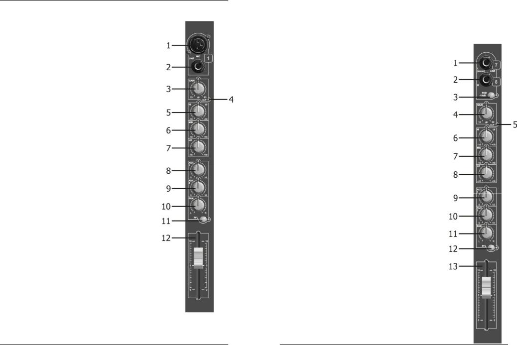
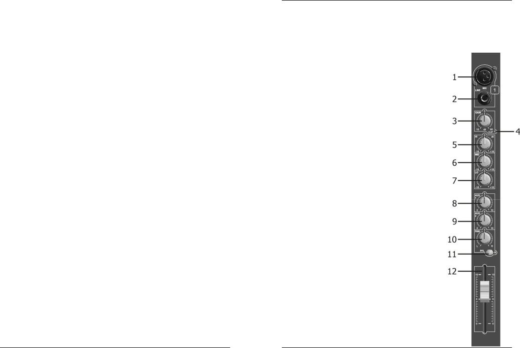
MONO MICROPHONE/LINE INPUT CHANNEL
1. 3 PIN FEMALE XLR SOCKET INPUT
Balanced input wiring: Pin 1 = Ground (sleeve)
|
Pin 2 = Positive signal |
|
|
Pin 3 |
= Negative signal |
Unbalanced input wiring: |
Pin 1 |
= Ground |
|
Pin 2 = Signal |
|
|
Pin 3 |
= Ground |
Input impedance: 2k Ohm
Input sensitivity: 0.8mV RMS (-60dB)
2. 1/4" STEREO JACK SOCKET INPUT
Balanced input wiring: Tip = Positive signal Ring = Negative signal Sleeve = Ground
Unbalanced input wiring: Tip = Signal
Ring = Ground Sleeve = Ground
(Mono jack plug will automatically give this)
Input impedance: >50K Ohm
Input sensitivity: 25mV RMS (-30dB)
3. GAIN CONTROL
Allows maximum input signal control and will accommodate most microphones of both low or high impedance to 600 Ohm as well as Phantom Power (48 Volt) types. The line input can be anything from keyboard through to line level feeds from other equipment. Gain range:
XLR input +15 to +60dB Jack input –15 to +30dB
4. CLIP LED
This warning will illuminate 4dB before clipping and will remain on for a short period. For optimal input channel running level, adjust Gain Control until Clip indicator illuminates while signal peaks are present. Then
adjust the gain setting until Clip indicator is off. This will give optimal signal to noise.
5. EQ CONTROL ‘HIGH’
This control allows 16dB of cut or boost to the high frequencies.
6. EQ CONTROL ‘MID’
This control allows 16dB of cut or boost to the mid frequencies.
7. EQ CONTROL ‘LOW’
This control allows 16dB of cut or boost to the low frequencies.
8. AUX SEND 1
This auxiliary send control is ‘Post-fade’ and can be used to control the mix of inputs being processed by effects, etc. Its level will change with the channel fader (12).
9. AUX SEND 2
This auxiliary send control is ‘Pre-fade’ and can be used to control the mix of inputs to an independent output such as monitoring. Its level will not change with channel fader (12).
Note: the Post-Fade option can only be selected by your service engineer.
10. PAN CONTROL
This control is used to set the stereo balance of the input signal and can ‘Pan’ it fully to the left or right.
ENGLISH |
OPERATION MANUAL |
11. PFL SWITCH
This switch and indicator allows pre-fade listen of input signals through the headphone and Led meters (useful while setting gains or trouble shooting).
12. 60mm FADER
This slide control provides level control of input signal to the main stereo mix output and will also control the Post-Fade Aux Send 1.
STEREO LINE INPUT CHANNEL
1. LINE INPUT LEFT OR MONO – 1/4" Mono Jack Socket
If the input is connected to a mono source use this connection
only as the signal will automatically be routed to the right input also.
Input wiring:
Tip = Signal Sleeve = Ground Input impedance: 10K Ohm
Input sensitivity: 24.5mV (-30dBm)
2. LINE INPUT RIGHT – 1/4" Mono Jacket Socket
Input wiring:
Tip = Signal Sleeve = Ground Input impedance: 10K Ohm
Input sensitivity: 24.5mV (-30dBm)
3. PAD SWITCH
Operation of this switch reduces the input sensitivity by 10Db allowing it to be used with high output devices such as CD players as well as musical instruments.
4. GAIN CONTROL
The panel marking at 0dB is a true reference to 0dBm when the –10dB Pad is engaged.
Range: +10dB
5. CLIP LED
This warning light will illuminate 4dB before clipping and will remain on for a short period. For optimal input channel running level, adjust Gain Control until Clip indicator illuminates while signal peaks are present.
Then adjust the gain setting until Clip indicator is off. This will give optimal signal to noise.
Note: If EQ controls are altered this Gain/Clip setting will need adjustment.
6. EQ CONTROL ‘HIGH’
This control allows 16dB of cut or boost to the high frequency content of the input signal.
7. EQ CONTROL ‘MID’
This control allows 6dB of cut or boost to the mid frequencies.
8. EQ CONTROL ‘LOW’
This control allows 6dB of cut or boost to the low frequencies.
9. AUX SEND 1
This auxiliary send control is ‘Post-fade’ and can be used to control the mix of inputs being processed by effects, etc.
Its level will change with the input fader (13).
10. AUX SEND 2
This auxiliary send control is ‘Pre-fade’ and can be used to control the mix of inputs to an independent output such as monitoring. Its level will NOT change with input fader.
Note: The Post-fade option can only be selected by your service engineer.
11. BALANCE CONTROL
This control is used to set the stereo balance of the input signal and can pan it fully to the left or right.
12. PFL SWITCH
This switch and indicator allows pre-fade listen of input signals through the headphone and Led meters (useful while setting gains or trouble shooting).
JB SYSTEMS® |
3/41 |
MM-10 |
JB SYSTEMS® |
4/41 |
MM-10 |
ENGLISH |
OPERATION MANUAL |
13. 60mm FADER
This Slide control provides level control of input signal to the main stereo mix output and will also control the Post-fade Aux Send 1.
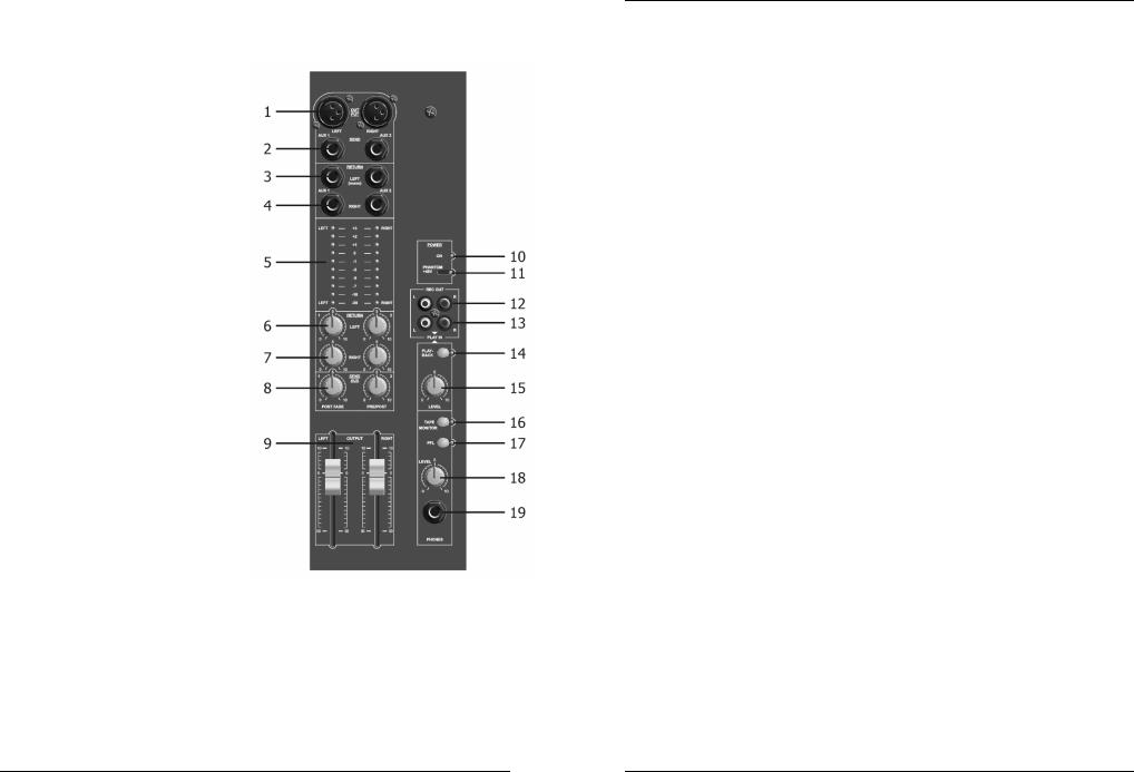
STEREO OUTPUT CHANNEL
1. STEREO OUTPUT - 3 pin Male XLR Socket
Output wiring: |
|
Balanced: |
Unbalanced: |
Pin 1= Ground |
Pin 1 = Ground |
|
(sleeve) |
Pin 2 = Positive Signal |
Pin 2 = Signal |
Pin 3 = Negative Signal Pin 3 = no connection
Nominal Output Level:
Balanced +6dBm (1.55V RMS variable to +10/16dB)
Unbalanced 0dBm (0.775V RMS variable to +10/16dB)
Impedance:
Output: <50 Ohm Minimum Load: 600
Ohm
2.AUX SEND OUTPUT – 1/4" Jack Mono Socket (unbalanced) output
Output wiring:
Tip = Signal |
Sleeve = Ground |
Nominal Output Level:
0dBm (0.775V RMS variable to +10dBm)
Impedance:
Output: <50 Ohm Minimum Load: 5K Ohm
3.AUX RETURN LEFT/MONO – 1/4" Jack Mono Socket Input
(If used as mono input it will automatically connect the input to the AUX Return Right socket)
Output wiring: |
|
Tip = Signal |
Sleeve = Ground |
Input impedance: 10K Ohm
Input sensitivity: 250mV RMS (-10DBm)
4.AUX RETURN RIGHT/MONO – 1/4" Jack Mono Socket Input
Same as (3) Aux Return Left/Mono.
5.LED METER
This is a 10 segment Led meter with VU calibration providing a signal monitor range from –20dB to 3dB with a change of colour at the nominal 0dB position.
6. AUX RETURN LEFT LEVEL CONTROL
This level control will set the desire amount of return signal on to the main left output mix only.
7. AUX RETURN RIGHT LEVEL CONTROL
This level control will set the desired amount of return signal on to the main right output mix only. (Use in conjunction with left level (6) when mixing a mono input signal)
8. MASTER AUX SEND OUTPUT LEVEL CONTROL
This level control sets the desired output level of Aux send mix to the output socket (it’s best set at N°7 when Finitially setting up). Subsequently adjust to level required by external equipment.
ENGLISH OPERATION MANUAL
9. MASTER OUTPUT FADER CONTROL
This Slide control is used to set the required overall output level to the power amplifier (or other equipment). The calibration shows a suggested nominal running level, referenced ‘0’ (10dB boost is available if required).
10. ON INDICATOR
This led indicates that the mixer power is on.
11. PHANTOM SWITCH
This switch is recessed to prevent accidental operation and has a corresponding red LED indicator; it should NOT be operated while the mixer is live.
NOTE:
It should be pre-selected during setting up with the main output faders and MIC input gain controls down.
ALL XLR MIC inputs will be phantom powered when selected. Some microphones that do NOT require phantom supply may not operate or are damaged – check instructions.
The Jack Line inputs will be unaffected and can be used as normal. (Your service station may be able to disable the Phantom Power)
12.STEREO RECORD OUTPUT – Left and Right RCA Socket Outputs (unbalanced)
The signal is derived from the main stereo output mix after the output faders. Nominal ‘0’ Output Level: -10dBv(316mVRMS)
Output impedance: 600 Ohm Load impedance (min): 5K Ohm
13. STEREO PLAYBACK INPUT – Left and Right RCA Socket Inputs (unbalanced)
Signal is routed to the main stereo output before the faders and the monitoring system. Normal Input Sensitivity: 316mV RMS (-10dBv)
Input impedance: 5K Ohm
14. PLAYBACK SWITCH
Allows ON/OFF control of Playback input signal onto the main stereo output mix.
15. PLAYBACK LEVEL CONTROL
Level control of the 2-track tape playback onto the main stereo output of the mixer (before the main output faders) set for desired mix.
16. TAPE MONITOR SWITCH
This switch sets the Headphone and Led Meter Monitoring system over to Tape Playback monitoring (Before the playback switch and level control).
17. PFL SWITCH
This switch sets the Headphone and Led Meters system over to PFL (input pre-fade listen) monitoring. It works in conjunction with PFL switches on each input channel.
18. HEADPHONE LEVEL CONTROL
This control is used in conjunction with the switch to monitor signals within the mixer. With both Tape Monitor and PFL switches ‘OFF’ the headphone system and Led meters will monitor the main stereo output.
19. HEADPHONE OUTPUT – 1/4" Stereo Jack Socket Output
Output wiring: Tip = left signal Ring = right signal Sleeve = ground
Minimum Load impedance: 40 Ohm
JB SYSTEMS® |
5/41 |
MM-10 |
JB SYSTEMS® |
6/41 |
MM-10 |
ENGLISH OPERATION MANUAL
SPECIFICATIONS
Power Supply: |
AC 230 V, 50Hz |
Fuse: |
1A/250V |
Frequency response: |
15-20.000Hz |
THD + noise: |
<0.01% @ 1kHz, 0dB |
S/N Ratio (IHF-A): |
>80dB |
Micro inputs: |
200-600 Ohm/balanced |
Line inputs: |
300mV @ 10kΩ |
Record output: |
775mV @ 50kΩ |
Master output: |
775mV @ 600Ω |
Tone controls: |
+/-16dB @ 10kHz / 600Hz / 60Hz |
Dimensions: |
483(W) x 360(H) x 80(D) mm |
Weight: |
7.8kg |
Every information is subject to change without prior notice
You can download the latest version of this user manual on our website: www.beglec.com
FRANCAIS |
|
MODE D’EMPLOI |
|
|
|
|
|
|
Nous vous remercions d’avoir acheté ce produit JB Systems®. Veuillez lire ce mode d’emploi très attentivement afin de pouvoir exploiter toutes les possibilités de cet appareil.
CARACTERISTIQUES
Cet appareil ne produit pas d’interférences radio. Il répond aux exigences nationales et européennes. La conformité a été établie et les déclarations et documents correspondants ont été déposés par le fabricant.
Table de mixage P.A.
Pour mixage des micros et des petits groups
6 canaux Mono, 2 canaux Stéréo
Entrée balancée micro et ligne pour chaque canal
Réglage de tonalité à 3 bandes
2 sorties auxiliaires
Entrée cassette, dirigée vers la sortie master
Alimentation “Phantom” de 48V
Sortie balancée (gauche et droite)
AVANT L’UTILISATION
Quelques instructions importantes:
Avant d’utiliser cet appareil, assurez-vous de l’absence de dommage lié au transport. En cas d’endommagement, n’utilisez pas l’appareil et contactez le vendeur.
Important: Cet appareil a quitté notre usine en parfaite condition et bien emballé. Il est primordial que l’utilisateur suive les instructions de sécurité et avertissements inclus dans ce manuel. La garantie ne s’applique pas en cas de dommage lié à une utilisation incorrecte. Le vendeur ne prend pas la responsabilité des défauts ou de tout problème résultant du fait de n’avoir pas tenu compte des mises en garde de ce manuel.
Conservez ce manuel dans un endroit sûr pour toute consultation future. Si vous vendez l’appareil, assurez-vous d’y joindre ce manuel également.
Afin de protéger l’environnement, merci de recycler les emballages autant que possible.
Vérifiez le contenu:
Vérifiez si la boite contient les articles suivants :
Mode d’emploi
MM-10
Câble secteur.
INSTRUCTIONS DE SECURITE:
ATTENTION: afin de réduire le risque d’électrocution, CAUTION n’enlevez jamais le couvercle de l’appareil. Il n’y a aucune pièce à l’intérieur de l’appareil que vous pouvez remplacer vous-même. Confiez l’entretien uniquement à des techniciens
qualifiés.
La flèche dans un triangle met l'utilisateur en garde contre la présence de haute tension sans isolation dans l'appareil qui peut causer un risque d'électrocution.
Un point d'exclamation dans un triangle prévient de la présence d'instructions de fonctionnement et de maintenance se trouvant dans le manuel, fourni avec l'appareil.
Ce symbole signifie : uniquement pour usage à l'intérieur
Ce symbole signifie : Lire le mode d’emploi.
Afin d’éviter tout risque d’incendie ou de choc électrique, ne pas exposer cet appareil à la pluie ou l’humidité.
JB SYSTEMS® |
7/41 |
MM-10 |
JB SYSTEMS® |
8/41 |
MM-10 |
FRANCAIS |
MODE D’EMPLOI |
Pour éviter la formation de condensation à l’intérieur de l’appareil, patientez quelques minutes pour laisser l’appareil s’adapter à la température ambiante lorsqu’il arrive dans une pièce chauffée après le transport. La condensation empêche l’unité de fonctionner en performance optimale et peut même causer des dommages.
Cette unité est destinée à une utilisation à l’intérieur uniquement.
Ne pas insérer d’objet métallique ou verser un liquide dans l’appareil. Aucun objet rempli de liquides, tels que des vases, ne peut être placé sur cet appareil. Risque de choc électrique ou de dysfonctionnement. Si un corps étranger est introduit dans l’unité, déconnectez immédiatement de la source d’alimentation.
Aucune source de flamme nue, telle que les bougies allumées, ne peut être placée sur l'appareil.
Ne pas couvrir les ouvertures de ventilation, un risque de surchauffe en résulterait.
Ne pas utiliser dans un environnement poussiéreux et nettoyez l’unité régulièrement.
Ne pas laisser l’unité à portée des enfants.
Les personnes non expérimentées ne doivent pas utiliser cet appareil.
La température ambiante maximum d’utilisation de l’appareil est de 40°C. Ne pas l’utiliser au-delà de cette température.
Débranchez toujours l’appareil si vous ne l’utilisez pas de manière prolongée ou avant d’entreprendre des réparations.
Les installations électriques ne peuvent être faites que par du personnel qualifié et conformément aux régulations de sécurité électrique et mécanique en vigueur dans votre pays.
Assurez-vous que la tension d’alimentation de la source d’alimentation de la zone dans laquelle vous vous trouvez ne dépasse pas celui indiqué à l’arrière de l’appareil.
La prise sera toujours accessible pour que le cordon secteur puisse être enlevé à chaque moment.
Le cordon d’alimentation doit toujours être en condition parfaite. Mettez immédiatement l’unité hors tension si le cordon est écrasé ou endommagé.
Ne laissez jamais le cordon d’alimentation entrer en contact avec d’autres câbles !
Quand l’interrupteur principal est dans la position OFF, cet appareil n'est pas complètement isolé du courant 230V!
L’appareil doit être à la masse selon les règles de sécurités.
Utilisez toujours les câbles appropriés et certifiés lorsque vous installez l’unité.
Pour éviter tout choc électrique, ne pas ouvrir l’appareil. En dehors du fusible principal, il n’y a pas de pièces pouvant être changées par l’utilisateur à l’intérieur.
Ne jamais réparer ou court-circuiter un fusible. Remplacez systématiquement un fusible endommagé par un fusible et de mêmes type et spécifications électriques !
En cas de problèmes de fonctionnement sérieux, arrêtez toute utilisation de l’appareil et contactez votre revendeur immédiatement.
Utilisez l’emballage d’origine si l’appareil doit être transporté.
Pour des raisons de sécurité, il est interdit d’apporter toute modification à l’unité non spécifiquement autorisée par les parties responsables.
CONSEILS D'INSTALLATION:
Installer l'appareil dans un lieu bien aéré, à l'abri de l'humidité et des fortes températures.
Placer et utiliser l'appareil à proximité de sources de chaleur telles que spots, amplis,… pourrait affecter ses performances et même endommager l'appareil.
L'appareil peut être installé dans un rack 19''. Fixer l'appareil en utilisant les 4 trous pour vis sur la face avant. Assurez-vous d'utiliser des vis de la bonne dimension (vis non fournies). Essayez d'éviter les vibrations et les coups lors du transport.
En cas d'installation dans un 'flight case', assurer une bonne ventilation afin d'évacuer la chaleur produite par l'appareil.
Pour éviter la condensation à l'intérieur, laisser l'appareil s'adapter à la nouvelle température ambiante après le transport. La condensation peut altérer les performances de l'appareil.
NETTOYAGE:
Nettoyez l’appareil à l’aide d’un chiffon doux, légèrement humide. Evitez d’introduire de l’eau à l’intérieur de l’appareil. N’utilisez pas de produits volatiles tels que le benzène ou le thinner qui peuvent endommager l’appareil.
FRANCAIS MODE D’EMPLOI
CONNEXIONS
Pour plus d'informations sur les connections, voyez le chapitre suivant.
Assurez-vous d'éteindre la table de mixage avant d'effectuer les différentes connections. Dans ce mode d'emploi, il est question d'entrée ligne ou “line inputs”. Il s'agit en fait d'un terme générique pour désigner des entrées avec un niveau compris entre 750mV et 2V. Ceci inclus les lecteurs de CD, tuners, vidéos,…
FONCTIONS
ENTREE MONO MICRO/LINE
1. ENTRÉE FEMELE XLR POUR MICROPHONE
Mode balancé: Pin 1 = Masse Pin 2 = Positif Pin 3 = Négatif
Mode non-balancé: Pin 1 = Masse
Pin 2 = Point chaud
Pin 3 = Masse
Impédance d’entrée: 2K Ohm
Sensibilité d’entrée: 0.8 mV RMS (-60dB)
2. ENTRÉE LIGNE STEREO 1/4’’
Mode balancé: Pointe = Positif Anneau = Négatif
Châssis = Masse
Mode non-balancé: Pointe = Positif Anneau = Masse
Châssis = Masse
(Une fiche jack mono donne automatiquement ceci)
Impédance d’entrée: >50K Ohm Sensibilité d’entrée : 25 mV RMS (-30dB)
3. RÉGLAGE DE GAIN
Permet un réglage d’entrée maximal et convient à la plupart des micros avec une impédance jusqu’à 600 Ohm comme ceux de type Phantom Power (48 Volt).
Gain Range: Entrée XLR +15 à +60dB Entrée Jack –15 à +30db
4.CLIP PEAK LED (INDICATEUR DE NIVEAU MAXIMUM)
L’indicateur d’écrêtage s’allume 4dB avant le signal maximum et restera allumé pendant une courte période.
NB : si le réglage de tonalité (cf. point 5,6,7) est modifié, le réglage du Gain doit être ajusté.
5.CONTRÔLE (EQ) DE TONALITÉ HIGH (AIGUES)
Ce réglage permet un réglage allant de -16dB à 16dB pour des fréquences aiguës.
6. CONTRÔLE (EQ) DE TONALITÉ MID (MOYENNES)
Ce réglage permet un réglage allant de -16dB à 16dB pour des fréquences moyennes.
7. CONTRÔLE (EQ) DE TONALITÉ LO (BASSES)
Ce réglage permet un réglage allant de -16dB à 16dB pour des fréquences basses.
8. CONTRÔLE AUX (Envoi 1)
Ce réglage d’auxiliaire est (Post-fade) et peut être utilisé pour contrôler des sources extérieures indépendantes comme le monitoring. Piloté par le fader d’entrée (12).
JB SYSTEMS® |
9/41 |
MM-10 |
JB SYSTEMS® |
10/41 |
MM-10 |
 Loading...