


LED DJ-BAR
POWERED LED 4BAR FOR DJ’s
LED DJ-BAR |
POWERED LED 4BAR FOR DJ’s |
Operation Manual EN
Mode d'emploi FR
Gebruiksaanwijzing NL
Bedienungsanleitung DE
Manual de instrucciones ES
Manual do utilizador PT
WWW.BEGLEC.COM
Copyright © 2009 by BEGLEC comm.v.a.
‘t Hofveld 2 ~ B1702 Groot-Bijgaarden ~ Belgium
Reproduction or publication of the content in any manner, without express permission of the publisher, is prohibited. Version: 1.0
EN - DISPOSAL OF THE DEVICE
Dispose of the unit and used batteries in an environment friendly manner according to your country regulations.
FR - DÉCLASSER L’APPAREIL
Débarrassez-vous de l’appareil et des piles usagées de manière écologique Conformément aux dispositions légales de votre pays.
NL - VERWIJDEREN VAN HET APPARAAT
Verwijder het toestel en de gebruikte batterijen op een milieuvriendelijke manier conform de in uw land geldende voorschriften.
DU - ENTSORGUNG DES GERÄTS
Entsorgen Sie das Gerät und die Batterien auf umweltfreundliche Art und Weise gemäß den Vorschriften Ihres Landes.
ES - DESHACERSE DEL APARATO
Reciclar el aparato y pilas usadas de forma ecologica conforme a las disposiciones legales de su pais.
PT - COMO DESFAZER-SE DA UNIDADE
Tente reciclar a unidade e as pilhas usadas respeitando o ambiente e em conformidade com as normas vigentes no seu país.

ENGLISH |
OPERATION MANUAL |
OPERATION MANUAL
Thank you for buying this JB Systems® product. To take full advantage of all possibilities and for your own safety, please read these operating instructions very carefully before you start using this unit.
FEATURES
This unit is radio-interference suppressed. This product meets the requirements of the current European and national guidelines. Conformity has been established and the relevant statements and documents have been deposited by the manufacturer.
This device has been designed to produce decorative effect lighting and is used in light show systems.
Stylish and extremely compact powered 4BAR containing 4 ultra thin RGB LED-projectors
Each LED-projector contains 212 high-power 5mm LEDs (70 red + 71 green + 71 blue) for exceptional high light output (exceeding the output of traditional PAR56 300W lamps!)
High quality “Hewlett Packard® / Agilent® ” LED technology!
LED-Projector beam angles = 15°
Energy saving: uses only 67W (instead of 1200W for traditional 4x PAR56-300W)
Perfect for mobile applications: only 106cm long, 9cm thick and 8kg!
Many applications possible: Discotheques, DJs, hiring companies, ...
Very smooth RGB color changes thanks to high freq. dimming electronics
0-100% dimming and ultra fast strobe function (no additional strobes needed!)
Excellent built-in programs for wonderful, ever changing, light shows!
Different working modes:
Standalone: automatic or beat synchronized color patterns (optional CA-8 controller possible)
Master/slave mode: up to 42 sets can be used together for wonderful preprogrammed, music synchronized lightshows.
DMX-controlled (4, 13 or 16 channel mode for maximum flexibility)
Controlling up to 42 units is child’s play using the optional LEDCON 02 remote!
4-digit menu driven display to select all possible functions
Black anodized ALU enclosure with sliding mechanism: can be fixed in ALU-truss using standard clamps.
Standard 35mm stand adapter included.
5m mains cable included.
BEFORE USE
Before you start using this unit, please check if there’s no transportation damage. Should there be any, do not use the device and consult your dealer first.
Important: This device left our factory in perfect condition and well packaged. It is absolutely necessary for the user to strictly follow the safety instructions and warnings in this user manual. Any damage caused by mishandling is not subject to warranty. The dealer will not accept responsibility for any resulting defects or problems caused by disregarding this user manual.
Keep this booklet in a safe place for future consultation. If you sell the fixture, be sure to add this user manual.
Check the contents:
Check that the carton contains the following items:
LED DJ-BAR, including 4 passive LED panels
1pc DMX signal cable 10m
1pc Power cable 5m
1pc 35mm stand adapter
ENGLISH OPERATION MANUAL
SAFETY INSTRUCTIONS:
CAUTION |
CAUTION: To reduce the risk of electric shock, do not |
|
remove the top cover. No user-serviceable parts inside. |
|
|
|
Refer servicing to qualified service personnel only. |
The lightning flash with arrowhead symbol within the equilateral triangle is intended to alert the use or the presence of un-insulated “dangerous voltage” within the product’s enclosure that may be of sufficient magnitude to constitute a risk of electric shock.
The exclamation point within the equilateral triangle is intended to alert the user to the presence of important operation and maintenance (servicing) instructions in the literature accompanying this appliance.
This symbol means: indoor use only
This symbol means: Read instructions
To protect the environment, please try to recycle the packing material as much as possible.
A new light effect sometimes causes some unwanted smoke and/or smell. This is normal and disappears after some minutes.
To prevent fire or shock hazard, do not expose this appliance to rain or moisture.
To avoid condensation to be formed inside, allow the unit to adapt to the surrounding temperatures when bringing it into a warm room after transport. Condense sometimes prevents the unit from working at full performance or may even cause damages.
This unit is for indoor use only.
Don’t place metal objects or spill liquid inside the unit. Electric shock or malfunction may result. If a foreign object enters the unit, immediately disconnect the mains power.
Locate the fixture in a well ventilated spot, away from any flammable materials and/or liquids. The fixture must be fixed at least 50cm from surrounding walls.
Don’t cover any ventilation openings as this may result in overheating.
Prevent use in dusty environments and clean the unit regularly.
Keep the unit away from children.
Inexperienced persons should not operate this device.
Maximum save ambient temperature is 40°C. Don’t use this unit at higher ambient temperatures.
Make sure the area below the installation place is free from unwanted persons during rigging, de-rigging and servicing.
Always unplug the unit when it is not used for a longer time or before you start servicing.
The electrical installation should be carried out by qualified personal only, according to the regulations for electrical and mechanical safety in your country.
Check that the available voltage is not higher than the one stated on the rear panel of the unit.
The power cord should always be in perfect condition. Switch the unit immediately off when the power cord is squashed or damaged. It must be replaced by the manufacturer, its service agent or similarly qualified persons in order to avoid a hazard.
Never let the power-cord come into contact with other cables!
This fixture must be earthed to in order comply with safety regulations.
Don’t connect the unit to any dimmer pack.
Always use an appropriate and certified safety cable when installing the unit.
In order to prevent electric shock, do not open the cover. There are no user serviceable parts inside.
Never repair a fuse or bypass the fuse holder. Always replace a damaged fuse with a fuse of the same type and electrical specifications!
In the event of serious operating problems, stop using the fixture and contact your dealer immediately.
The housing and the lenses must be replaced if they are visibly damaged.
Please use the original packing when the device is to be transported.
Due to safety reasons it is prohibited to make unauthorized modifications to the unit.
Important: Don’t use the effect in the presence of persons suffering from epilepsy.
JB SYSTEMS® |
1/77 |
LED DJ-BAR |
JB SYSTEMS® |
2/77 |
LED DJ-BAR |
ENGLISH |
OPERATION MANUAL |
OVERHEAD RIGGING
Important: The installation must be carried out by qualified service personal only. Improper installation can result in serious injuries and/or damage to property. Overhead rigging requires extensive experience! Working load limits should be respected, certified installation materials should be used, the installed device should be inspected regularly for safety.
Make sure the area below the installation place is free from unwanted persons during rigging, de-rigging and servicing.
Locate the fixture in a well ventilated spot, far away from any flammable materials and/or liquids. The fixture must be fixed at least 50cm from surrounding walls.
The device should be installed out of reach of people and outside areas where persons may walk by or be seated.
Before rigging make sure that the installation area can hold a minimum point load of 10times the device’s weight.
Always use a certified safety cable that can hold 12times the weight of the device when installing the unit. This secondary safety attachment should be installed in a way that no part of the installation can drop more than 20cm if the main attachment fails.
The device should be well fixed; a free-swinging mounting is dangerous and may not be considered!
Don’t cover any ventilation openings as this may result in overheating.
The operator has to make sure that the safety-relating and machine-technical installations are approved by an expert before using them for the first time. The installations should be inspected every year by a skilled person to be sure that safety is still optimal.
BUILDING TOGETHER AND INSTALLING ON A LIGHT STAND:
Unpack all parts and put them on a table.
Push the following parts in the correct order in the sliding section (B) located on the bottom of the 4BAR:
Bolt (A) for LED panel1
Bolt (A) for LED panel2
Nut for 35mm Adapter (H)
Bolt (A) for LED panel3
Bolt (A) for LED panel4
Refer to the drawing to see how the 4 panels should be fixed correctly:
First add the leather washer (C)
Add the metal washer (D)
Add the LED PANEL (F) Important: the connector should be on the same side as the LED power signal cable (G) of the 4bar.
Add the black knob (E) and fasten well.
Insert the LED power cable (G) in the back of the four corresponding panels.
When the 4 panels are fixed to the 4bar, you can install the 35mm adapter
(I)simply turn the thread of the adapter in the nut (H) (nut already in place) until it is well tightened.
Open the knob of the adapter (J) and put the assembled LED DJ-BAR on top of a stable light stand.
Tighten the knob of the adapter (J) and connect all cables (see later)
You can still align the panels in different directions.
Done!
ENGLISH |
OPERATION MANUAL |
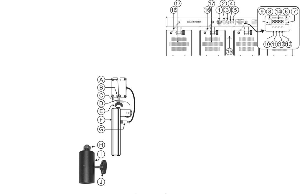
DESCRIPTION:
1.Mains input with IEC socket and integrated fuse holder, connect the supplied mains cable here.
2.DMX input
3.DMX output
4.¼” Jack input for the optional CA-8 hand controller
5.Internal microphone
6.Slave LED: is lit when the unit is in slave mode
7.Sound LED: blinks to the rhythm of the music while the unit is in audio mode
8.DMX LED: is lit when the unit receives a DMX-signal
9.Master LED: is lit when the unit is switched as master
10.MENU button: used to select the different menu items
11.DOWN button: to go back in the menu and to lower the values shown on the display.
12.UP button: to go up in the menu and to increase the values shown on the display.
13.ENTER button: used to confirm your choice.
14.DISPLAY shows the various menus and the selected functions.
15.35mm STAND ADAPTER: used to put the LED 4Bar easily on top of a light stand
16.Special cables with LED power signal for the passive LED panels
17.Passive LED panels
HOW TO SETUP:
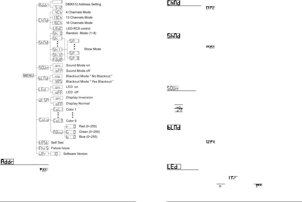
MAIN MENU:
To select any of the menu options, press the MENU button up to when the required option is shown on the display.
Select the function with the ENTER button. The display will blink.
Use DOWN and UP button to choose the desired menu option.
Once the required menu option is selected, press the ENTER button to select. To go back to the functions without any change press the MENU button for about 2 seconds or just wait 8 seconds. The menu structure is shown below.
JB SYSTEMS® |
3/77 |
LED DJ-BAR |
JB SYSTEMS® |
4/77 |
LED DJ-BAR |
ENGLISH |
OPERATION MANUAL |
DMX512 Address Setting
Used to set the starting address in a DMX setup.
Press the MENU button until 


 is shown on the display.
Press the ENTER button, the display starts blinking.
Use DOWN and UP buttons to change the DMX512 address.
Once the correct address shows on the display, press the ENTER button to save it.
(or automatically return to the main functions without any change after 8 seconds)
To go back to the functions without any change press the MENU button again for about 2seconds.
ENGLISH |
OPERATION MANUAL |
Channel Mode
Press the MENU button until 


 is shown on the display.
Press the ENTER button, the display starts blinking.
Use DOWN and UP button to select one of the available channel modes.
Once the mode is selected, press the ENTER button to setup
(or automatically return to the main functions without any change after 8 seconds)
To go back to the functions without any change press the MENU button again for about 2seconds.
IMPORTANT: select mode  when the LED DJ-BAR is used with the LEDCON-02 controller!
Show Mode
Used to choose to select one of the preprogrammed shows when used in standalone or master/slave mode.
Press the MENU button until 


 is showing on the display.
Press the ENTER button, the current show starts blinking in the display. Use DOWN and UP buttons to select one of the preprogrammed shows:
 all shows played in random mode.
 to
to  12 different built-in shows.
 fading from one color to another.
Except for the random show (Show 0) you will also be asked to select a running speed for the static mode. With the UP/DOWN buttons you can select  (slow) to
  (fast).
Press the ENTER button to save it. (or automatically return to the main functions without any change after
8 seconds)
To go back to the functions without any change press the MENU button again for about 2seconds.
Sound Mode
Used to choose the desired sound mode to trigger the shows.
Press the MENU button until  is shown on the display.
Press the ENTER button, the display starts blinking.
Use DOWN and UP button to select one of the available channel modes:


 (sound mode ON) the shows are triggered by the internal microphone.


 (sound mode OFF) the shows are triggered by the speed selected with the shows.
Once the mode is selected, press the ENTER button to setup
(or automatically return to the main functions without any change after 8 seconds)
To go back to the functions without any change press the MENU button again for about 2seconds.
Blackout Mode
Blackout mode: when no DMX-signal is detected, the unit goes in blackout.
No blackout mode: when no DMX-signal is detected, the unit automatically switches to master mode. ALWAYS set to “No Blackout” when the unit is used in master (or master/slave) mode!!!
Press the MENU button until 


 is shown on the display.
Press the ENTER button, the current selection starts blinking in the display.
Use DOWN and UP button to select Y E S(blackout) or n o (no blackout) mode.
Once the mode is selected, press the ENTER button to save it.
(or automatically return to the main functions without any change after 8 seconds)
To go back to the functions without any change press the MENU button again for about 2seconds.
Led Display
Display on: display is always on.
Display off: display is off when not used.
Press the MENU button until the display shows 


 .
.
Press the ENTER button, the display starts blinking.
Use DOWN and UP buttons to select 


 (display always on) or


 (display off when not used).
Once the mode is selected, press the ENTER button to save it.
(or automatically return to the main functions without any change after 8 seconds)
JB SYSTEMS® |
5/77 |
LED DJ-BAR |
JB SYSTEMS® |
6/77 |
LED DJ-BAR |

ENGLISH |
OPERATION MANUAL |
To go back to the functions without any change press the MENU button again for about 2seconds.
Display Inversion
Display normal: display is readable when the unit is on the floor.
Display inversion: display is readable when the unit is mounted upside down.
Press the MENU button until the display shows 
Press the ENTER button, the display starts blinking.
Use DOWN and UP buttons to select 


 (display inversion) or


 (normal display).
Once the mode is selected, press the ENTER button to save it.
(or automatically return to the main functions without any change after 8 seconds)
To go back to the functions without any change press the MENU button again for about 2seconds.
Color Mode
Used to put a certain color on all 4 LED panels.
Press the MENU button until the display shows  .
.
Press the ENTER button, the display starts blinking.
Use the DOWN and UP buttons to select one of the 9 pre-programmed colors ( to
to  ) and press ENTER to confirm.
You can also choose the manual color mode (display =  ) if you want to compose your own custom color. Once you press ENTER the following screens appear:
 Brightness of RED color can be changed from 0% to 100% (r..0 to r255)
 Brightness of GREEN color can be changed from 0% to 100% (G..0 to G255)
 Brightness of BLUE color can be changed from 0% to 100% (b..0 to B255)
Press the MENU button for about 2 seconds to save the settings and return to normal working mode. (or automatically return to the main functions without any change after 8 seconds)
 Self-Test
Run a built-in self-test program
Press the MENU button until the display shows 
Press the ENTER button, the display starts blinking: the unit runs abuilt-in self-test program.
To go back to the functions without any change press the MENU button again for about 2seconds.
Fixture Hours
Used to show the number of working hours of the unit.
Press the MENU button until 


 is blinking on the display.
Press the ENTER button to show the number of working hours in the display.
To go back to the functions without any change press the MENU button again for about 2seconds.
 Software version:
Used to show the software version of the unit.
Press the MENU button until  blinks on the display.
Press the ENTER button to show the software version of the unit.
To go back to the functions without any change press the MENU button again for about 2seconds.
ELECTRICAL INSTALLATION + ADDRESSING
Important: The electrical installation should be carried out by qualified personal only, according to the regulations for electrical and mechanical safety in your country.
Electrical installation for 1 standalone unit:
Just insert the mains cable. The unit starts working immediately in stand-alone mode.
Remark1: You can connect a CA-8 remote controller to the unit if you want to have more control. Refer to “how to operate the unit” to learn how to do this.
Remark2: if there’s no output, please make sure to set the unit in master mode and set the blackout mode to “NO” (see previous chapter)
ENGLISH |
OPERATION MANUAL |
Electrical installation for two or more units in master/slave:
Connect 2 to maximum 16 units together using good quality balanced microphone cables. The first unit in the chain will automatically act as master, the other units will act automatically as slaves.
Make sure that all units are connected to the mains.
Done!
Remark: You can connect a CA-8 remote controller to the master unit if you want to have more control over the master/slave operation
Electrical installation in Master/slave-mode with the LEDCON-02 remote:
Up to 42 LED DJ-BAR units can be daisy chained and connected to the output of en optional LEDCON02 remote using a good quality balanced cable.
All connected units are automatically switched as slaves.
IMPORTANT REMARK: to make sure everything works well you MUST set the LED DJ-BAR in “LEdC” channel mode and perform the “automatic address distribution” feature on the LEDCON-02 before using the set for the first time!!! (check the user manual of your LEDCON-02 to see how this is done)
Electrical installation in DMX-mode:
The DMX-protocol is a widely used high speed signal to control intelligent light equipment. You need to “daisy chain” your DMX controller and all the connected units with a good quality balanced cable.
Both XLR-3pin and XLR-5pin connectors are used, however XLR-3pin is more popular because these cables are compatible with balanced audio cables.
Pin layout XLR-3pin: Pin1 = GND ~ Pin2 = Negative signal (-) ~ Pin3 = Positive signal (+) Pin layout XLR-5pin: Pin1 = GND ~ Pin2 = Negative signal (-) ~ Pin3 = Positive signal
(+)~ Pins4+5 not used.
To prevent strange behavior of the light effects, due to interferences, you must use a 90Ω to 120Ω terminator at the end of the chain. Never use Y-splitter cables, this simply won’t work!
Make sure that all units are connected to the mains.
Each light effect in the chain needs to have its proper starting address so it knows which commands from the controller it has to decode. In the next section you will learn how to set the DMX addresses.
HOW TO SET THE RIGHT STARTING ADDRESS:
Refer to the previous chapter (DMX-512 address setting) to learn how to set the starting address on this unit. The starting address of each unit is very important. Unfortunately it is impossible to tell you in this user manual which starting addresses you have to set because this completely depends on the controller you will use… So please refer to the user manual of your DMX-controller to find out which starting addresses you must set.
JB SYSTEMS® |
7/77 |
LED DJ-BAR |
JB SYSTEMS® |
8/77 |
LED DJ-BAR |

ENGLISH |
OPERATION MANUAL |
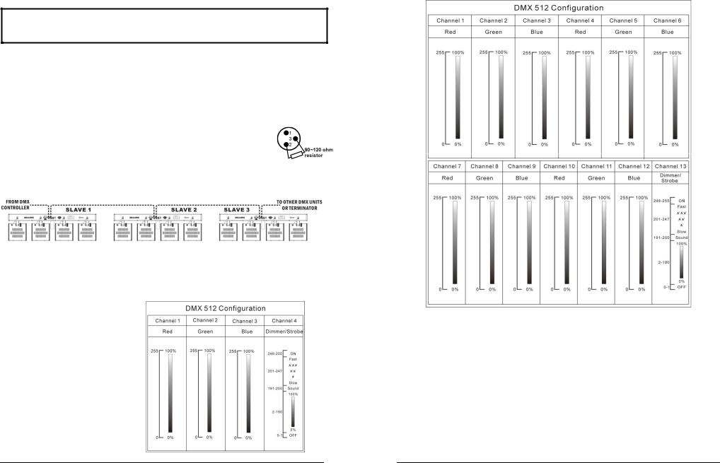
DIFFERENT DMX-CONFIGURATIONS OF TAURUS:4 CHANNEL MODE:
13 CHANNEL MODE:
ENGLISH |
OPERATION MANUAL |
16 CHANNEL MODE:
HOW TO OPERATE THE UNIT
YOU CAN OPERATE THE UNIT IN 4 WAYS:
o By master/slave built-in preprogram function o By CA-8 easy controller
o By universal DMX controller
oBy LEDCON-02 controller
BY MASTER/SLAVE BUILT-IN PREPROGRAM FUNCTION:
Select this function when you want an instant show. By linking the units in master/slave connection, the first unit will control the other units to give an automatic, sound activated, synchronized light show. Its DMX input will have nothing plugged into it, and its master-LED will be constantly on and sound-LED will flash to the music.
Remark1: All functions should be selected on the master unit.
Remark2: A CA-8 “easy controller” can eventually be used on the master unit.
JB SYSTEMS® |
9/77 |
LED DJ-BAR |
JB SYSTEMS® |
10/77 |
LED DJ-BAR |
ENGLISH |
OPERATION MANUAL |
BY CA-8 EASY CONTROLLER:
Just connect this small controller to the 1/4” jack of the master unit, and you will be able to control the following
FUNCTIONS:
|
BUTTON |
|
|
|
|
ACTIONS |
|
|
|
|
STANDBY |
|
|
|
|
To blackout all LED panels |
|
|
|
|
|
|
1.Synchronous strobe in |
|
Red Orange |
Show1 Show2 |
1. Slow speed |
|
|
|
|
|
|
white color |
|
Yellow Green |
… Show12 Fade |
2. Middle speed |
|
|
|
|
2.Synchronous strobe in |
|
Cyan Blue |
|
3. Fast speed |
|
|
|
|
|
|
rainbow colors |
|
Purple Magenta |
|
|
|
|
FUNCTION |
|
3.Sound strobe in white |
|
White Manual |
|
|
|
|
|
|
4.Sound strobe in |
|
color |
|
|
|
||
|
|
|
|
rainbow colors |
|
|
|
|
|
|
|
|
|
PS: |
|
|
|
|
|
|
|
|
|
In this mode random |
|
|
|
|
|
|
|
|
|
show (Sh 0) is active |
|
|
|
|
|
|
|
|
|
|
|
|
|
|
|
|
MODE |
|
|
Strobe select |
|
Color select |
Show select |
Speed setting |
|
|
|
|
|
|
|||||
|
|
|
(LED OFF) |
|
(LED ON) |
(LED slow blinking) |
(LED fast blinking) |
|
|
|
|
|
|
|
|
|
|
|
|
BY UNIVERSAL DMX CONTROLLER:
You can use any standard DMX-controller. First choose the desired DMX-channel mode and give the unit the correct DMX start address. (see earlier to learn how this should be done)
BY LEDCON-02 CONTROLLER:
Make sure the LED DJ-BAR channel mode is set to “LEdC” (see earlier) and perform the automatic address function on the LEDCON-02 before you start using the set! Further explanations and instructions can be found in the user manual of the LEDCON-02.
MAINTENANCE
Make sure the area below the installation place is free from unwanted persons during servicing.
Switch off the unit, unplug the mains cable and wait until the unit has been cooled down.
During inspection the following points should be checked:
All screws used for installing the device and any of its parts should be tightly fastened and may not be corroded.
Housings, fixations and installations spots (ceiling, truss, suspensions) should be totally free from any deformation.
When an optical lens is visibly damaged due to cracks or deep scratches, it must be replaced.
The mains cables must be in impeccable condition and should be replaced immediately when even a small problem is detected.
In order to protect the device from overheat the cooling fans (if any) and ventilation openings should be cleaned monthly.
The interior of the device should be cleaned annually using a vacuum cleaner or air-jet.
The cleaning of internal and external optical lenses and/or mirrors must be carried out periodically to optimize light output. Cleaning frequency depends on the environment in which the fixture operates: damp, smoky or particularly dirty surroundings can cause greater accumulation of dirt on the unit’s optics.
Clean with a soft cloth using normal glass cleaning products.
Always dry the parts carefully.
Clean the external optics at least once every 30 days.
Clean the internal optics at least every 90 days.
Attention: We strongly recommend internal cleaning to be carried out by qualified personnel!
ENGLISH OPERATION MANUAL
SPECIFICATIONS
Mains Input: |
AC 100V - 240V, 50Hz/60Hz |
Power consumption: |
Max. 67 Watt |
Fuse: |
T3,15A / 250V slow blow (20mm glass) |
Sound Control: |
Internal microphone |
DMX connections: |
3pin XLR male / female |
DMX channels used: |
4/13/16 channels |
Lamp: |
848 LEDs (4x 212 LEDs) |
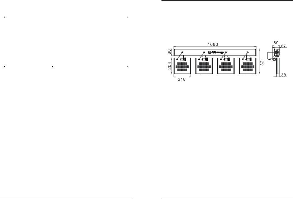
Size: |
see drawing |
Weight: |
8 kg |
Every information is subject to change without prior notice
You can download the latest version of this user manual on our website: www.beglec.com
JB SYSTEMS® |
11/77 |
LED DJ-BAR |
JB SYSTEMS® |
12/77 |
LED DJ-BAR |

FRANÇAIS |
MODE D’EMPLOI |
MODE D’EMPLOI
Merci d’avoir choisi ce produit JB Systems®. Pour votre sécurité et pour une utilisation optimale de toutes les possibilités de l’appareil, lisez attentivement cette notice avant utilisation.
EN VOUS INSCRIVANT POUR LA LETTRE D’INFORMATION VOUS SEREZ TOUJOURS
TENU AU COURANT DES DERNIERES NOUVELLES CONCERNANT NOS PRODUITS: NOUVEAUTES, ACTIONS SPECIALES, JOURNEES PORTES OUVERTES, ETC.
SURFEZ SUR: WWW.BEGLEC.COM
CARACTERISTIQUES
Cet appareil ne produit pas d’interférences radio. Il répond aux exigences nationales et européennes. La conformité a été établie et les déclarations et documents correspondants ont été déposés par le fabricant.
Cet appareil a été conçu pour la production de jeux de lumières décoratifs et est utilisé dans des spectacles lumineux.
Barre d'alimentation à 4 sorties, aussi élégante que compacte, équipée de 4 projecteurs RGB à LED ultra fins.
Chaque projecteur à LED est doté de 212 LED de 5 mm de grande puissance (70 rouges + 71 vertes + 71 bleues) : cela conduit à une puissance lumineuse exceptionnelle (qui dépasse en fait la puissance de sortie des projecteurs traditionnels comme les PAR56 de 300 watts !).
Technologie LED de haute qualité (“Hewlett Packard® / Agilent®”).
L'angle de dispersion du faisceau de ce projecteur à LED est de 15°.
Economie d'énergie : l'appareil ne consomme que 67W (au lieu de 1200W pour les traditionnels 4 x PAR56 de 300W).
Idéal pour des applications de nature itinérante : seulement 106 cm de long, 9 cm d'épaisseur et 8 kilos !
Plusieurs applications sont possibles : discothèques, DJ, firmes de location, ...
Le passage d'une couleur à une autre se fait en douceur grâce à l'électronique de qualité (high freq. dimming ).
Gradateur allant de 0 % à 100 %, ainsi que fonction stroboscopique des plus rapides (pas besoin de posséder de stroboscope supplémentaire.
Excellents programmes intégrés donnant lieu à de splendides light shows qui changent sans arrêt.
Plusieurs modes de fonctionnement sont disponibles :
Mode autonome : motifs de couleurs automatiques ou synchronisés au rythme de la musique (on peut utiliser le contrôleur CA-8, disponible en option)
MASTER / SLAVE mode (mode maître / esclave) : on peut utiliser jusqu'à 42 appareils ensemble pour construire de splendides light shows préprogrammés et synchronisés à la musique
contrôle via DMX (4, 13 ou 16 canaux pour un maximum de flexibilité)
Assurer le contrôle de 42 appareils au maximum devient un jeu d'enfant quand on a recours au contrôleur à distance en option, le LEDCON 02
Ecran géré par menus et disposant de 4 caractères permettant de sélectionner toutes les fonctions existantes.
Boîtier en ALU noir anodisé disposant d'un mécanisme coulissant. L'appareil peut être fixé sur des superstructures en ALU avec les fixations standard.
Un adaptateur pour statif au standard 35 mm est inclus.
Un câble d'alimentation secteur de 5 m est également inclus.
AVANT UTILISATION
Avant d’utiliser cet appareil, assurez-vous de l’absence de dommages liés au transport. En cas de dommages, n’utilisez pas l’appareil et contactez le vendeur.
Important: Cet appareil a quitté notre usine en parfaite condition et bien emballé. Il est primordial que l’utilisateur suive les instructions de sécurité et avertissements inclus dans ce manuel. La garantie ne s’applique pas en cas de dommage lié à une utilisation incorrecte. Le vendeur ne prend pas la responsabilité des défauts ou de tout problème résultant du fait de n’avoir pas tenu compte des mises en garde de ce manuel.
FRANÇAIS |
MODE D’EMPLOI |
Conservez ce manuel dans un endroit sûr pour toute consultation future. Si vous vendez l’appareil, assurez-vous d’y joindre ce manuel également.
Afin de protéger l’environnement, merci de recycler les emballages autant que possible.
Vérifiez le contenu:
Vérifiez si l’emballage contient bien les articles suivants:
Mode d'emploi
La LED DJ-BAR, y compris les 4 panneaux passifs à LED
Un câble de 10 m pour le signal DMX
Un câble d'alimentation de 5 m
Un adaptateur pour statif au standard 35 mm
INSTRUCTIONS DE SECURITE:
ATTENTION: afin de réduire le risque d’électrocution,
CAUTION n’enlevez jamais le couvercle de l’appareil. Il n’y a aucune pièce à l’intérieur de l’appareil que vous puissiez
remplacer vous-même. Confiez l’entretien uniquement à des techniciens qualifiés.
La flèche dans un triangle met l'utilisateur en garde contre la présence de haute tension sans isolation dans l'appareil, ce qui peut causer un risque d'électrocution.
Un point d'exclamation dans un triangle prévient de la présence d'instructions relatives au fonctionnement et à la maintenance se trouvant dans le manuel fourni avec l'appareil.
Ce symbole signifie: uniquement pour usage à l'intérieur.
Ce symbole signifie : Lire le mode d’emploi.
Afin de protéger l’environnement, merci de recycler les emballages autant que possible.
Un effet lumière neuf peut provoquer de la fumée et/ou une odeur non souhaitée, qui devrait disparaître après quelques minutes.
Afin d’éviter tout risque d’incendie ou de décharge électrique, ne pas exposer cet appareil à la pluie ou à l’humidité.
Pour éviter la formation de condensation à l’intérieur de l’appareil, patientez quelques minutes pour laisser l’appareil s’adapter à la température ambiante lorsqu’il arrive dans une pièce chauffée après le transport. La condensation empêche l'appareil de fonctionner manière optimale, et elle peut même causer des dommages.
Cet appareil est destiné à une utilisation à l’intérieur uniquement.
Ne pas insérer d’objet métallique ou renverser de liquide dans l’appareil. Aucun objet contenant un liquide, tels que des vases, ne peut être placé sur cet appareil. Cela risquerait de provoquer une décharge électrique ou un dysfonctionnement. Si un corps étranger est introduit dans l’appareil, déconnectez immédiatement de la source d’alimentation.
Aucune source de flamme nue, telle que des bougies allumées, ne peut être placée sur l'appareil.
Placez l’appareil dans un endroit bien ventilé, éloigné de tout matériau ou liquide inflammable. L’appareil doit être fixé à 50cm minimum des murs.
Ne pas couvrir les orifices de ventilation, un risque de surchauffe en résulterait.
Ne pas utiliser l'appareil dans un environnement poussiéreux et le nettoyer régulièrement.
Ne pas laisser l'appareil à portée des enfants.
Les personnes non expérimentées ne doivent pas utiliser cet appareil.
La température ambiante maximale d’utilisation de l’appareil est de 45°C. Ne pas l’utiliser au-delà de cette température.
Assurez-vous que la zone au-dessous du lieu d’installation ne comporte pas de personnes non concernées pendant le montage, le démontage et les opérations de maintenance.
Débranchez toujours l’appareil si vous ne l’utilisez pas de manière prolongée avant d’entreprendre des réparations.
Les installations électriques ne peuvent être faites que par du personnel qualifié et conformément aux règlements de sécurité électrique et mécanique en vigueur dans votre pays.
Assurez-vous que la tension d’alimentation de la source d’alimentation de la zone dans laquelle vous vous trouvez ne dépasse pas celle indiquée à l’arrière de l’appareil.
JB SYSTEMS® |
13/77 |
LED DJ-BAR |
JB SYSTEMS® |
14/77 |
LED DJ-BAR |

FRANÇAIS |
MODE D’EMPLOI |
Le cordon d’alimentation doit toujours être en parfait état. Mettez immédiatement l’unité hors tension si le cordon devait être écrasé ou endommagé. Pour éviter tout risque de choc électrique, le cordon doit être remplacé par le constructeur, son agent ou un technicien qualifié.
Ne laissez jamais le cordon d’alimentation entrer en contact avec d’autres câbles !
L’appareil doit être à la masse selon les règles de sécurité.
Ne pas connecter l’unité à un variateur de lumière.
Utilisez toujours des câbles appropriés et certifiés lorsque vous installez l'appareil.
Pour éviter toute décharge électrique, ne pas ouvrir l’appareil. Il n’y a pas de pièces pouvant être changées par l’utilisateur à l’intérieur.
Ne jamais réparer ou court-circuiter un fusible. Remplacez systématiquement un fusible endommagé par un fusible de même type et ayant les mêmes spécifications électriques !
En cas de problèmes de fonctionnement sérieux, arrêtez toute utilisation de l’appareil et contactez votre revendeur immédiatement.
La carrosserie et les lentilles doivent être remplacées si elles sont visiblement endommagées.
Utilisez l’emballage d’origine si l’appareil doit être transporté.
Pour des raisons de sécurité, il est interdit d’apporter une quelconque modification à l’unité non spécifiquement autorisée par les parties responsables.
Important: Ne pas utiliser d’effets en présence de personnes souffrant d’épilepsie.
INSTALLATION EN HAUTEUR
Important: L’installation doit être faite par du personnel qualifié uniquement. Une installation incorrecte peut causer des blessures sévères et/ou endommager l’appareil. L’installation en hauteur exige de l’expérience ! Les limites de charge doivent être scrupuleusement respectées, du matériel d’installation certifié doit être utilisé, et l’appareil installé doit subir des inspections de sécurité régulièrement.
Assurez-vous que la zone au-dessous du lieu d’installation ne comporte pas de personnes non concernées lors de l’installation, la désinstallation ou la maintenance.
Placez l’appareil dans un endroit bien ventilé, éloigné de tout matériau ou liquide inflammable. L’appareil doit être fixé à 50cm minimum des murs situés à proximité.
L’appareil doit être hors de portée du public et en dehors des zones de passage de personnes ou des zones où le public est installé.
Avant l’installation, assurez-vous que la zone d’installation pourra supporter, en son point de fixation, un minimum de 10 fois le poids de l’appareil.
Utilisez systématiquement un câble de sécurité qui peut supporter 12 fois le poids de l’appareil lors de
l’installation. Ce câble de sécurité secondaire doit être installé de manière à ce qu’aucune partie de l’appareil ne puisse descendre de plus de 20 cm si le support principal tombe.
L’appareil doit être bien fixé, un montage à balancement est dangereux et ne devrait pas être pris en considération !
Ne pas couvrir les orifices de ventilation pour éviter tout risque de surchauffe.
L’utilisateur doit s’assurer que les installations techniques et de sécurité sont bien approuvées par un expert avant la première utilisation. Les installations doivent être inspectées chaque année par du personnel qualifié pour assurer une sécurité optimale.
MONTAGE ET INSTALLATION SUR UN STATIF POUR JEU DE
LUMIERES :
Déballez toutes les pièces et étalez-les sur une table.
Introduisez les pièces suivantes, dans le bon ordre, dans la section à glissière (B) située à la base de la barre :
Boulon (A) pour le panneau à LED 1
Boulon (A) pour le panneau à LED 2
Ecrou pour l'adaptateur (H) 35 mm
Boulon (A) pour le panneau à LED 3
Boulon (A) pour le panneau à LED 4
FRANÇAIS |
MODE D’EMPLOI |
Prière de se reporter à la figure pour comprendre comment il convient de fixer les 4 panneaux :
Ajoutez tout d'abord la rondelle en cuir (C)
Ajoutez ensuite la rondelle en métal ((D)
Ajoutez le panneau à LED (F) Important : le connecteur doit impérativement se trouver du même côté que le câble (G) de la barre d'alimentation véhiculant le signal de puissance des LED.
Ajoutez le bouton noir (E) et fixez solidement
Insérez le câble véhiculant le signal de puissance des LED à l'arrière des 4 panneaux correspondants.
Quand les 4 panneaux sont bien fixés à la barre d'alimentation, vous pouvez installer l'adaptateur 35 mm (I) tournez simplement le filet de l'adaptateur dans l'écrou (H), l'écrou étant déjà en place, et ce jusqu'à ce que le tout soit solidement fixé.
Ouvrez le bouton de l'adaptateur (J) et déposez la LED DJ-BAR préalablement assemblée sur le dessus d'un statif bien stable et destiné aux jeux de lumières.
Serrez à suffisance le bouton de l'adaptateur (J) et connectez tous les câbles (prière de se reporter plus loin).
A ce stade, vous êtes toujours en mesure d'orienter les panneaux dans différentes directions.
C'est terminé !
DESCRIPTION
1.Entrée pour l'alimentation secteur dotée d'un socket IEC et d'une protection à fusible intégrée ; c'est ici que vous devez connecter le câble d'alimentation secteur.
2.Connecteur d’entrée DMX
3.Connecteur de sortie DMX
4.Prise ¼” utilisée pour connecter le contrôleur CA-8 optionnel
5.Microphone interne
6.LED 'SLAVE' : elle est allumée quand l'appareil est en mode esclave
7.LED 'SOUND' : elle clignote suivant le rythme de la musique quand l'appareil est en mode audio
8.LED 'DMX' : elle est allumée quand l'appareil reçoit un signal DMX
9.LED 'MASTER' : elle est allumée quand l'appareil est utilisé en tant qu'appareil maître
10.Touche 'MENU' : utilisée pour sélectionner les différents chapitres du menu
11.Touche 'DOWN' : utilisée pour reculer dans le menu et pour diminuer les valeurs affichées par l'écran.
12.Touche 'UP' : utilisée pour avancer dans le menu et pour augmenter les valeurs affichées par l'écran.
13.Touche 'ENTER' : utilisée pour confirmer votre sélection.
14.L'écran montre les différents menus et les fonctions sélectionnées.
15.ADAPTATEUR DE STATIF 35 mm : est utilisé pour fixer facilement la barre d'alimentation en haut d'un statif pour projecteurs.
16.Câbles spécifiques véhiculant le signal de puissance vers les panneaux à LED passifs
17.Panneaux à LED passifs
JB SYSTEMS® |
15/77 |
LED DJ-BAR |
JB SYSTEMS® |
16/77 |
LED DJ-BAR |
FRANÇAIS |
MODE D’EMPLOI |
COMMENT REGLER L'APPAREIL
MENU PRINCIPAL:
Pour sélectionner une option du menu, appuyez sur la touche MENU jusqu’à ce que la fonction désirée apparaisse à l’écran.
Sélectionnez la fonction à l’aide de la touche ENTER. L’écran clignotera.
Utilisez les touches DOWN et UP pour choisir dans le menu l'option désirée.
Dès que vous avez sélectionné l'option désirée dans le menu, appuyez sur la touche ENTER pour confirmer. Après 8 secondes l’écran retournera automatiquement aux fonctions principales sans avoir modifié quoi que ce soit. Pour retourner aux fonctions sans effectuer de changements, appuyez pendant environ 2 secondes sur la touche MENU. La structure du menu est affichée ci-contre.
FRANÇAIS |
MODE D’EMPLOI |
Reglage de l’adresse DMX512 |
|
Est utilisé pour régler l’adresse de départ dans une configuration DMX. |
|
Appuyez sur la touche MENU jusqu’à ce que 


 soit affiché à l’écran.
Appuyez sur la touche ENTER, l’écran commence à clignoter.
Utilisez les touches DOWN et UP pour changer l’adresse DMX512.
Quand l’adresse désirée est affiché à l’écran, appuyez sur la touche ENTER pour confirmer votre choix. (Où il retournera automatiquement aux fonctions principales sans aucune modification après 8
secondes)
Pour retourner aux fonctions sans effectuer de changements, appuyez à nouveau sur la touche MENU pendant environ 2 secondes.
Channel Mode (Mode canal)
Appuyez sur la touche MENU jusqu'à ce que les lettres 


 soient affichées par l'écran.
Appuyez sur la touche ENTER, ce qui a pour conséquence que l'écran commence à clignoter.
Utilisez les touches DOWN et UP pour sélectionner l'un des modes disponibles.
Une fois que le mode est sélectionné, appuyez sur la touche ENTER pour confirmer (ou vous retournerez vers les fonctions principales si aucune activité n'est détectée par l'appareil pendant 8 secondes ).
Pour retourner vers les fonctions sans effectuer de changements, appuyez de nouveau sur la touche MENU pendant environ 2 secondes.
IMPORTANT : sélectionnez le mode |
quand la barre d'alimentation est utilisée avec le |
contrôleur LEDCON-02 ! |
|
Show Mode
Mode utilisé pour sélectionner l'un des shows préprogrammés quand on est en mode 'standalone' (autonome) ou en mode 'master/slave' (maître/esclave).
Appuyez sur la touche MENU jusqu’à ce que 


 est affiché à l’écran.
Appuyez sur la touche ENTER, le show en mémoire commence à clignoter à l'écran.
Utilisez les touches DOWN et UP pour sélectionner un des shows préprogrammés :
 tous les shows sont reproduits suivant le mode aléatoire.
 à
à  12 shows différents et préprogrammés.
 fondu enchaîné d'une couleur vers une autre.
A part pour le mode aléatoire (Show 0), l'appareil vous demandera aussi de sélectionner une vitesse de
défilement pour le mode dit 'statique'. En appuyant sur les touches UP et DOWN, vous pouvez sélectionner une valeur entre  (vitesse lente) et
  (vitesse rapide).
Appuyez sur la touche ENTER pour l'enregistrer.
(Où il retournera automatiquement aux fonctions principales sans aucune modification après 8 secondes) Pour retourner aux fonctions sans effectuer de changements, appuyez à nouveau sur la touche MENU pendant environ 2 secondes.
Sound Mode
Est utilisé pour sélectionner le mode musical qui contrôlera les shows.
Appuyez sur la touche MENU jusqu’à ce que  est affiché à l’écran.
Appuyez sur la touche ENTER, la sélection en mémoire commence à clignoter à l'écran.
Utilisez les touches DOWN et UP pour sélectionner un des modes disponibles:


 (mode son activé) les shows sont pilotés à l’aide du micro intégré.


 (mode son désactivé) les shows sont pilotés par la vitesse des shows sélectionés
Quand le mode est sélectionné, appuyez sur la touche ENTER pour confirmer
(Où il retournera automatiquement aux fonctions principales sans aucune modification après 8 secondes)
Pour retourner aux fonctions sans effectuer de changements, appuyez à nouveau sur la touche MENU pendant environ 2 secondes
JB SYSTEMS® |
17/77 |
LED DJ-BAR |
JB SYSTEMS® |
18/77 |
LED DJ-BAR |

FRANÇAIS MODE D’EMPLOI
Mode Black out
Black out mode: quand aucun signal DMX est détecté, l’appareil se met en black out.
Mode « pas de black-out »: quand aucun signal DMX n'est détecté, l’appareil se met automatiquement à fonctionner en mode master.
Sélectionez TOUJOURS “No Blackout” quand l’appareil est utilisé en tant que master (ou en mode maître/esclave) !!!
Appuyez sur la touche MENU jusqu’à ce que 


 soit affiché à l’écran.
Appuyez sur la touche ENTER, la sélection en mémoire commence à clignoter à l'écran.
Utilisez les touches DOWN et UP pour sélectionner 'YES' (mode black out) ou 'NO' (mode sans black out).
Dès que le mode de fonctionnement est affiché à l’écran, appuyez sur la touche ENTER pour confirmer votre choix.
(Où il retournera automatiquement aux fonctions principales sans aucune modification après 8 secondes) Pour retourner aux fonctions sans effectuer de changements, appuyez à nouveau sur la touche MENU pendant environ 2 secondes.
Led Display
Display on: l’écran est toujours allumé.
Display off: l’écran est éteint quand il n’est pas utilisé.
Appuyez sur la touche MENU jusqu’à ce que l’écran affiche


 .
.
Appuyez sur la touche ENTER, l’écran commence à clignoter.
Utilisez les touches DOWN et UP pour sélectionner 


 (écran toujours allumé) ou


 (écran éteint si pas utilisé).
Dès que le mode de fonctionnement est affiché à l’écran, appuyez sur la touche ENTER pour confirmer votre choix.
(Où il retournera automatiquement aux fonctions principales sans aucune modification après 8 secondes) Pour retourner aux fonctions sans effectuer de changements, appuyez à nouveau sur la touche MENU
pendant environ 2 secondes.
Inversion Display
Display normal: possibilité de lire ce qui est affiché à l’écran quand l’appareil est posé par terre. Display inversion: possibilité de lire ce qui est affiché à l’écran quand l’appareil est suspendu.
Appuyez sur la touche MENU jusqu’à ce que l’écran affiche 
Appuyez sur la touche ENTER, l’écran commence à clignoter.
Utilisez les touches DOWN et UP pour sélectionner 


 (affichage inversé) ou


 (affichage normal).
Appuyez sur la touche ENTER pour confirmer
(Où il retournera automatiquement aux fonctions principales sans aucune modification après 8 secondes) Pour retourner vers les fonctions, appuyez sur la touche MENU pendant environ 2 secondes.
Color Mode
Ce mode est utilisé pour afficher une même couleur sur les 4 panneaux à LED.
Appuyez sur la touche MENU jusqu’à ce que l’écran affiche  .
.
Appuyez sur la touche ENTER, l’écran commence à clignoter.
En appuyant sur les touches UP et DOWN, vous pouvez sélectionner l'une des neuf couleurs préprogrammées (de  à
à  ) ; appuyez ensuite sur ENTER pour confirmer.
Vous pouvez également choisir le mode couleur manuel (écran =  ) si vous désirez composer votre propre couleur "maison". Après avoir appuyé sur la touche ENTER, les écrans suivants défilent :
 Vous pouvez faire varier la clarté ou la couleur rouge de 0 à 100 % (r..0 to r255)
 Vous pouvez faire varier la clarté ou la couleur verte de 0 à 100 % (G..0 to G255)
 Vous pouvez faire varier la clarté ou la couleur bleue de 0 à 100 % (B...0 to B255)
Appuyez sur le bouton MENU pendant environ 2 secondes pour enregistrer vos réglages et retourner ensuite vers le mode de fonctionnement normal.
(Où il retournera automatiquement aux fonctions principales sans aucune modification après 8 secondes)
FRANÇAIS |
MODE D’EMPLOI |
 Self-Test
Effecutez un autotest
Appuyez sur la touche MENU jusqu’à ce que  soit affiché à l’écran.
Appuyez sur la touche ENTER, l’écran commence à clignoter: l’appareil execute une programme autotest. Pour retourner vers les fonctions sans effectuer des changements, appuyez sur la touche MENU pendant
environ 2 secondes
Fixture Hours
Vous communique le nombre d’heures de service de l’appareil.
Appuyez sur la touche MENU jusqu’à ce que 


 clignote à l’écran.
Appuyez sur la touche ENTER pour que l’appareil affiche le nombre d’heures de service à l’écran.
Pour retourner aux fonctions, appuyez sur la touche MENU pendant environ 2 secondes.
 Version du software
Fonction utilisée pour montrer sous quelle version du software fonctionne l'appareil.
Appuyez sur la touche MENU jusqu'à ce que les lettres  se mettent à clignoter à l'écran.
Appuyez sur la touche ENTER pour afficher sous quelle version du software fonctionne l'appareil
Pour retourner vers les fonctions, appuyez sur la touche MENU pendant environ 2 secondes.
INSTALLATION ELECTRIQUE + ADRESSAGE
 Important : L'installation électrique devrait être effectuée uniquement par du personnel qualifié, suivant les normes de sécurité relatives à l'électricité et à la mécanique dans votre pays.
Installation électrique pour 1 appareil en fonctionnement seul:
Installez simplement le câble secteur. L’appareil commencera à fonctionner immédiatement en mode autonome.
Remarque 1: vous pouvez brancher une commande à distance CA-8 sur l’appareil si vous souhaitez avoir plus de possibilités de contrôle. Référez-vous à la section 'Comment utiliser l'appareil' pour apprendre à effectuer cette procédure correctement.
Remarque 2: s'il n'y a pas de sortie, veuillez vous assurer que l'appareil soit bien réglé en mode 'master' et réglez le mode blackout sur « NO » (se reporter au chapitre précédent).
Installation électrique pour deux ou plusieurs appareils en maître/esclave:
Branchez de 2 à 16 appareils au maximum ensemble en utilisant des câbles symétriques pour micro de bonne qualité. Le premier appareil dans la chaîne se comportera automatiquement en tant que maître, les autres appareils se comporteront automatiquement en tant qu'esclaves.
Assurez-vous que les appareils sont tous branchés sur le secteur.
Et c’est terminé!
Remarque: vous pouvez brancher une commande à distance CA-8 sur l’appareil maître (master) si vous souhaitez avoir plus de contrôle sur le fonctionnement maître/esclave.
Installation électrique en mode maître / esclave avec la télécommande LEDCON-02 :
Vous pouvez raccorder jusqu'à 42 LED DJ-BAR suivant la technique des connexions en guirlandes
JB SYSTEMS® |
19/77 |
LED DJ-BAR |
JB SYSTEMS® |
20/77 |
LED DJ-BAR |
FRANÇAIS |
MODE D’EMPLOI |
(daisy chaining) et vous connecter à la sortie d'une télécommande (en option) LEDCON-02, en prenant garde d'utiliser du câble symétrique de bonne qualité.
Tous les appareils connectés basculeront automatiquement en mode esclave.
REMARQUE IMPORTANTE : afin de vous assurer que tout fonctionne correctement, vous devez ABSOLUMENT régler la LED DJ-BAR en mode canal 'LEdC' et effectuer l'opération 'automatic address distribution' sur le LEDCON-02 avant d'utiliser l'ensemble pour la première fois !!! (Prière de se reporter à la notice d'emploi de votre LEDCON-02 afin de voir comment faire)
Installation électrique en mode DMX :
Le protocole DMX est un signal à haute vitesse très utilisé pour contrôler des équipements lumineux intelligents. Vous devez connecter en guirlande (daisy chaining) votre contrôleur DMX et tous les appareils avec un câble symétrique de bonne qualité.
Les deux types de connecteurs XLR, ceux à 3 broches comme ceux à 5 broches, peuvent être utilisés ; cependant, les connecteurs à 3 broches se rencontrent plus fréquemment car ils sont compatibles avec les câbles audio symétriques.
Plan de câblage des XLR à 3 broches : Broche 1 = prise de terre ~ broche 2 = signal négatif (-) ~ broche 3 = signal positif (+)
Plan de câblage des XLR à 5 broches : Broche 1 = prise de terre ~ broche 2 = signal
négatif (-) ~ broche 3 = signal positif (+) ~ broches 4 et 5 : non utilisées.
Pour éviter des comportements étranges des effets lumineux dus aux interférences, vous devez utiliser une résistance de bouclage de 90 ohms à 120 ohms en fin de chaîne. Ne jamais utiliser de séparateur de câbles en forme de "Y", cela ne fonctionnera pas !
Assurez-vous que tous les appareils soient bien connectés au secteur.
Chaque effet lumineux de la chaîne doit avoir sa propre adresse de départ afin de savoir à quelle commande du contrôleur il doit obéir. Dans le chapitre qui suit, vous apprendrez à régler les adresses DMX.
COMMENT REGLER L’ADRESSE DE DEMARRAGE EXACTE:
Référez-vous au chapitre précédent (réglage de l’adresse DMX-512) pour apprendre à régler l’adresse de départ sur cet appareil. L’adresse de départ de chaque appareil est très importante. Malheureusement il est impossible de vous expliquer dans ce mode d’emploi quel adresse de démarrage vous devez introduire car cela dépends entièrement du contrôleur que vous utiliserez … veuillez donc vous référer au mode d’emploi de votre contrôleur DMX pour savoir quelle adresse vous devez utiliser.
CONFIGURATION DMX DU DJ-BAR :
Mode à 4 canaux :
FRANÇAIS |
MODE D’EMPLOI |
Modes à 13 canaux :
JB SYSTEMS® |
21/77 |
LED DJ-BAR |
JB SYSTEMS® |
22/77 |
LED DJ-BAR |
 Loading...