


Notice de Montage 29/04/02 14:49 Page 1
Declaration of Conformity
We, Harman Consumer International
2, route de Tours
72500 Chateau-du-Loir
FRANCE
declare that the car audio amplifiers JBL GTO 2000, GTO 4000 and GTO 6000 described in this owner’s manual are in compliance with technical standards
• EN 55020
Emmanuel Millot
Harman Consumer International
Chateau du Loir, France. 04/02
www.jbl.com
© 2002 harman consumer international Printed in France - 04/2002
G T O
2000 - 4000 - 6000
Owner’s Manual - Gebrauchsanleitung - Mode d’emploi Manual del usuario - Manuale dell’utente - Manual do Utilizador
Garmanual
Notice de Montage 29/04/02 14:49 Page 3
Thank you for purchasing |
y |
o |
u |
r |
all fuel lines, hydraulic |
|||||
a JBL GTO |
amplifier. In |
authorized JBL car-audio |
brake |
lines, vacuum |
||||||
order that we may better |
dealer about professional |
lines |
|
and |
||||||
serve |
you |
should |
you |
installation options. |
|
electrical wiring. |
Use |
|||
require warranty servi- |
|
|
|
|
extreme |
caution |
when |
|||
ce on your new ampli- |
|
|
|
|
cutting |
or drilling in |
||||
fier, |
please retain |
your |
Installation |
Warnings |
and around these areas. |
|||||
original purchase receipt |
and Tips |
|
|
|
|
|
• |
|
Before drilling or |
|
|
|
|
|
|
|
|
|
|
|||||||||||||||||
and |
return |
the |
enclosed |
• |
Always wear pro- |
|
cutting holes, use a uti- |
|
|
|
|
|
|
|
|
|
|
|||||||||||||||||||
w a r r a n t y |
tective |
eyewear |
when |
|
lity |
knife |
to |
remove |
|
|
|
|
|
|
|
|
|
|
||||||||||||||||||
registration card. |
|
|
using tools. |
|
|
|
|
unwanted |
fabric |
|
|
or |
|
|
|
|
|
|
|
|
|
|
||||||||||||||
|
|
|
|
|
|
|
|
• |
Turn off all audio |
|
vinyl to |
keep |
|
material |
|
|
|
|
|
|
|
|
|
|
||||||||||||
Important: Installation of |
systems and other elec- |
|
from snagging in a drill |
|
|
|
|
|
|
|
|
|
|
|||||||||||||||||||||||
a u t o m o t i v e |
s t e - |
trical |
devices |
before |
|
bit. |
|
|
|
|
|
|
|
|
|
|
|
|
|
|
|
|
|
|
|
|||||||||||
r |
|
|
e |
|
|
|
o |
you start. |
|
|
|
|
• |
|
When |
|
|
routing |
|
|
|
|
|
|
|
|
|
|
||||||||
components |
can |
require |
• |
Disconnect |
|
the |
|
cables, |
keep |
|
input- |
|
|
|
|
|
|
|
|
|
|
|||||||||||||||
extensive experience |
in |
negative (-) lead from |
|
signal cables away from |
|
|
|
|
|
|
|
|
|
|
||||||||||||||||||||||
performing |
a |
variety |
of |
your |
|
|
|
vehicle’s |
|
power cables and spea- |
Warning: |
Playing |
loud |
|||||||||||||||||||||||
mechanical and electrical |
battery. |
|
|
|
|
|
ker wires. |
|
|
|
|
|
|
music |
in |
an automobile |
||||||||||||||||||||
procedures. |
|
Although |
• |
Check |
clearances |
|
• |
|
When |
|
|
making |
can |
permanently damage |
||||||||||||||||||||||
these |
|
instructions |
on both sides of a plan- |
|
connections, ensure that |
your hearing as well as |
||||||||||||||||||||||||||||||
explain, |
in |
a |
general |
ned |
mounting surface |
|
they |
are |
secure |
|
and |
hinder |
your |
ability |
to |
|||||||||||||||||||||
sense, how to install GTO |
before |
drilling |
any |
|
properly insulated. |
|
|
|
hear |
traffic. We |
recom- |
|||||||||||||||||||||||||
amplifiers, they may not |
holes |
or |
installing |
any |
|
• |
|
If the amplifier’s |
mend |
listening |
at |
low |
||||||||||||||||||||||||
show the exact installa- |
screws. Remember |
that |
|
fuse |
must |
be |
|
replaced, |
levels while in your car. |
|||||||||||||||||||||||||||
tion |
methods |
for |
your |
the |
screws can |
extend |
|
use only the same type |
JBL |
accepts |
no |
liability |
||||||||||||||||||||||||
particular vehicle. If you |
behind the surface. |
|
|
and rating as that of the |
for |
hearing |
loss, bodily |
|||||||||||||||||||||||||||||
feel you lack the tools or |
• |
At the installation |
|
original. Do not substi- |
injury |
|
|
or |
property |
|||||||||||||||||||||||||||
n e c e s s a r y |
s |
i |
|
t |
e |
s |
, |
|
tute another kind. |
|
|
|
damage |
resulting |
from |
|||||||||||||||||||||
experience, |
|
ask |
locate and make a note of |
|
|
|
|
|
|
|
|
|
|
|
|
use or misuse of this |
||||||||||||||||||||
|
|
|
|
|
||||||||||||||||||||||||||||||||
Choosing a Location and Mounting the Amplifier |
|
|
battery. Pass the wire through a factory-installed |
|||||||||||||||||||||||||||||||||
Amplifiers need air to stay cool. Suitable locations are |
|
grommet |
in |
the |
firewall, or install |
a |
grommet |
if |
a |
|||||||||||||||||||||||||||
|
factory |
|
|
|
|
grommet |
|
|
is |
|
|
not |
||||||||||||||||||||||||
under seats (provided the amplifier doesn’t interfere |
|
|
|
|
|
|
|
|
|
|||||||||||||||||||||||||||
|
available. You must install, within 45 cm of the bat- |
|||||||||||||||||||||||||||||||||||
with |
|
|
|
|
|
|
|
|
|
|
|
|
|
the |
|
|||||||||||||||||||||
|
|
|
|
|
|
|
|
|
|
|
|
|
|
t |
|
|
|
|
|
|
e |
|
|
|
|
r |
|
|
|
|
y |
|||||
seat-adjustement mechanism), in the trunk or in any |
|
|
|
|
|
|
|
|
|
|
|
|
|
|
|
|||||||||||||||||||||
|
connection, a fuse holder and fuse with the same rating |
|||||||||||||||||||||||||||||||||||
location that provides enough air for the amp to cool |
|
|||||||||||||||||||||||||||||||||||
|
as the fuse in the amplifier’s chassis. This will pre- |
|||||||||||||||||||||||||||||||||||
itself. Do not mount the amplifier with the heat-sink |
|
|||||||||||||||||||||||||||||||||||
|
vent |
a |
short |
circuit |
from causing |
damage to |
the |
|||||||||||||||||||||||||||||
fins facing downward; this makes convection cooling of |
|
|||||||||||||||||||||||||||||||||||
|
amplifier or the car. Connect a wire |
|
|
|
|
|
|
|
||||||||||||||||||||||||||||
the amplifier impossible. |
|
|
|
|
|
|
|
|
Note: Bridging of GTO 6000 |
|||||||||||||||||||||||||||
Mount the amplifier so that it is not damaged by the |
|
between |
the |
REM terminal |
of |
the |
|
|
|
+ |
- |
|
|
|||||||||||||||||||||||
|
amplifier |
|
|
|
and |
|
|
the |
|
Front |
R+ |
L- |
|
|
||||||||||||||||||||||
feet of back-seat passengers or shifting cargo in the |
|
|
|
|
|
|
|
|
|
|||||||||||||||||||||||||||
|
“remote out” or power-antenna lead |
|
Rear |
R+ |
L- |
|
|
|||||||||||||||||||||||||||||
trunk. Mount the amplifier so that it remains dry - |
|
|
|
|
||||||||||||||||||||||||||||||||
|
on the vehicle’s radio. |
|
|
|
|
|
Sub |
R+ |
L- |
|
|
|||||||||||||||||||||||||
never |
|
|
mount |
|
an |
|
|
|
amplifier |
|
|
|
|
|
|
|
|
|||||||||||||||||||
|
|
|
|
|
|
|
|
|
|
|
|
|
|
|
|
|
|
|
|
|
|
|
|
|
|
|
|
|||||||||
outside the car or in the engine compartment. |
|
|
|
Wiring the Speaker-Output Connections |
|
|
|
|
|
|||||||||||||||||||||||||||
|
|
|
|
|
|
|
|
|
|
|
|
|
|
|
|
|
|
|
|
|
|
|
|
|||||||||||||
Using the amplifier as a template, mark the location of |
|
Connect the speakers, observing proper polarity, to |
||||||||||||||||||||||||||||||||||
|
the |
|
speaker-output |
|
barrier |
|
|
|
|
|
|
|
|
|
||||||||||||||||||||||
the |
mounting |
holes |
on the |
mounting |
surface, |
drill |
|
|
|
|
|
|
|
|
|
|
|
|
||||||||||||||||||
|
strip. The |
total |
impedance |
|
|
|
|
|
|
|
|
|
|
|||||||||||||||||||||||
pilot holes and attach the amplifier to the mounting |
|
|
|
|
|
|
|
|
|
|
|
|||||||||||||||||||||||||
|
of |
the |
speaker |
system |
|
|
|
|
|
|
|
|
|
|
||||||||||||||||||||||
surface |
with |
screws. Make |
sure |
the |
amplifier |
is |
|
|
|
|
|
|
|
|
|
|
|
|||||||||||||||||||
|
connected to the amplifier |
|
|
|
|
|
|
|
|
|
|
|||||||||||||||||||||||||
mounted securely. |
|
|
|
|
|
|
|
|
|
|
|
|
|
|
|
|
|
|
|
|
||||||||||||||||
|
|
|
|
|
|
|
|
|
|
when |
the |
amplifier |
|
is |
|
|
|
|
|
|
|
|
|
|
||||||||||||
Wiring the Power Connections |
|
|
|
|
|
|
|
|
|
|
|
|
|
|
|
|
|
|
||||||||||||||||||
|
|
|
|
|
|
|
driven in stereo must be |
|
|
|
|
|
|
|
|
|
|
|||||||||||||||||||
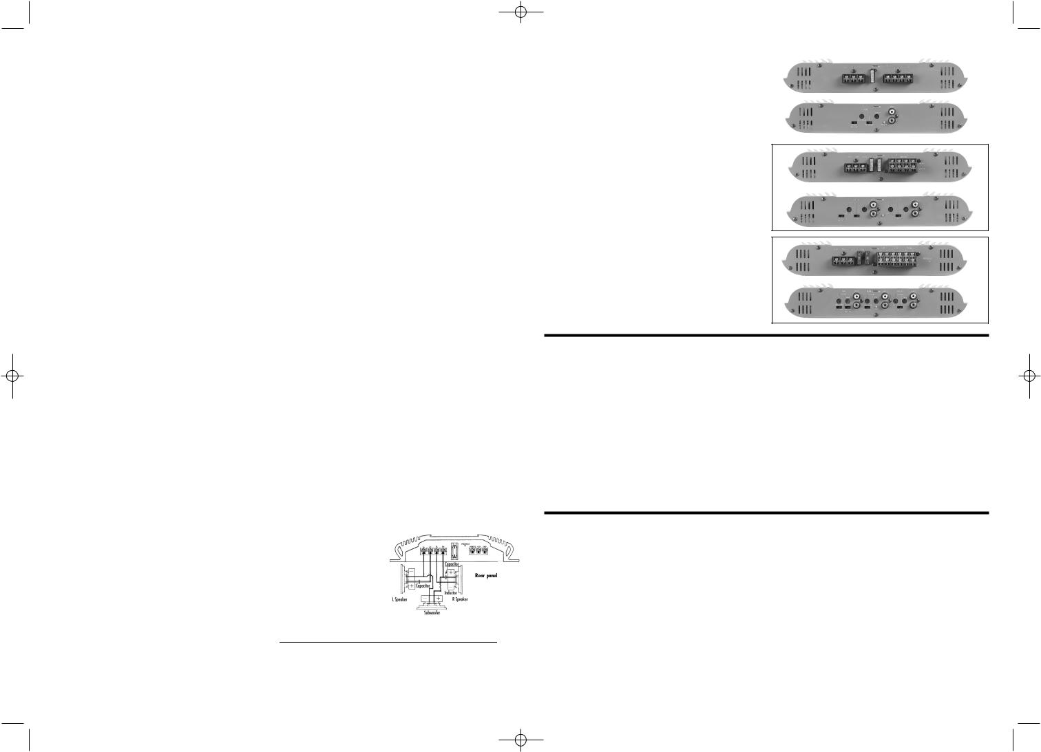
Refer to Figures 1-3 for connector locations. Use at |
|
|
|
|
|
|
|
|
|
|
|
|||||||||||||||||||||||||
|
least two ohms. |
|
|
|
|
|
|
|
|
|
|
|
|
|
|
|
||||||||||||||||||||
least 6 mm2 wire for power and ground connections. |
|
|
|
|
|
|
|
|
|
|
|
|
|
|
|
|
||||||||||||||||||||
|
If |
you |
are bridging |
|
the |
|
|
|
|
|
|
|
|
|
|
|||||||||||||||||||||
For |
power, remote and |
ground connections |
strip off |
|
|
|
|
|
|
|
|
|
|
|
|
|||||||||||||||||||||
|
amplifier, |
connect |
the |
|
|
|
|
|
|
|
|
|
|
|||||||||||||||||||||||
one end of each jacket to reveal bare wire for inser- |
|
|
|
|
|
|
|
|
|
|
|
|||||||||||||||||||||||||
|
wires |
to |
the |
terminals |
marked |
|
|
|
|
|
|
|
|
|||||||||||||||||||||||
tion |
|
|
|
|
|
|
into |
|
|
|
|
|
the |
|
|
|
|
|
|
|
|
|
||||||||||||||
|
|
|
|
|
|
|
|
|
|
|
|
“bridged”, |
observing |
proper |
polarity. The total |
|||||||||||||||||||||
barrier-strip connectors. Connect a wire from the |
|
|||||||||||||||||||||||||||||||||||
|
impedance of the speaker system connected to the |
|
||||||||||||||||||||||||||||||||||
|
|
|||||||||||||||||||||||||||||||||||
G |
|
|
|
|
|
|
N |
|
|
|
|
|
|
D |
|
|
FREQUENCY |
|
|
|
|
|
INDUCTOR |
|
|
|
CAPACITOR |
|
|
|||||||
connector on the amplifier to the nearest bare-metal |
|
amplifierCrossovermust be at6dB/octleast. LPfour(4 ohm)ohms in6dB/octbridged. HPmode(4 . |
|
|||||||||||||||||||||||||||||||||
|
ohm) |
|
|
|
|
|
|
|
|
|
|
|
|
|
|
|
|
|
|
|
||||||||||||||||
chassis |
component; scrape away the paint |
to ensure |
|
If you are running the amp in Tri-Mode (stereo and |
|
|||||||||||||||||||||||||||||||
|
|
|
75Hz |
|
|
|
|
|
|
8.0mH |
|
|
|
|
530µF |
|
|
|
||||||||||||||||||
g |
|
|
|
|
o |
|
|
|
o |
|
|
|
d |
|
mono simultaneously),100Hz |
connect6.4mH the satellite400µFspeakers |
|
|||||||||||||||||||
|
|
|
|
|
|
|
|
|
|
|
to |
|
125Hz |
|
|
|
|
|
5.0mH |
|
|
|
|
318µF |
the |
|
||||||||||
conductivity. Next, connect a wire between the BATT |
|
|
|
|
|
|
|
|
|
|
|
|
||||||||||||||||||||||||
|
|
|
150Hz |
|
|
|
|
|
4.2mH |
|
|
|
|
265µF |
|
|
|
|||||||||||||||||||
terminal on the amplifier and the POS (+) terminal of |
|
speaker175Hzconnector as you3would.6mH a pair of stereo227µF spea- |
|
|||||||||||||||||||||||||||||||||
|
kers. Connect the subwoofer to the terminals marked |
|||||||||||||||||||||||||||||||||||
the |
|
|
|
|
|
|
|
|
|
|
|
vehicle’s |
|
|||||||||||||||||||||||
|
|
|
|
|
|
|
|
|
|
|
|
|
|
|
|
|
|
|
|
|
|
|
|
|
|
|
|
|
|
|
|
|
||||
Wiring the Input-Signal Connections
Connect a pair of signal cables with RCA-type ends between the connectors on the amplifier and the RCAtype signal connectors on the source unit. If your radio has only speaker-level outputs, you must purchase a speaker-level-to-line-level adapter, commonly sold as an accessory.
System Setup and Adjustement
Refer to figures 1-3 for location of adjustement switches and controls.
Electronic Crossover
The electronic crossover can be selected as a 12dB/oct high-pass filter (HPF), 12dB/oct low-pass filter (LPF) or it can be defeated (OFF). The crossover frequency can be set at any frequency between 30Hz and 320Hz.
Input Sensitivity
initially, turn the input-sensitivity LEVEL control to its maximum (counterclockwise) position. Turn on the source unit and increase the volume control until it is approximately t h r e e - quarters of maximum-output level. Slowly increase the input LEVEL control (clockwise) while listening to the quality of the reproduced sound. When you hear distortion on the music peaks, turn the LEVEL control back slightly. This is the maximum undistorted output
level of your system. Turning |
the LEVEL control up |
Fig.1 |
GTO 2000 |
farther WILL NOT INCREASE THE OUTPUT P O W E R OF |
|
YOUR AMP! It will only decrease the amount of volu- |
|
me control rotation before the amp is at full output |
|
power. It will also increase the amount of extraneous |
|
noise in your system. |
|
|
|
Fig.2 |
GTO 4000 |
Fig.3 |
GTO 6000 |
Troubleshooting |
|
|
|
Symptom |
Likely Cause |
Solution |
|
|
|
||
No audio (power indicator is on) |
Speakers or input-signal cables dis- |
||
connected; |
Check connections, source, speakers. |
|
|
|
defective speaker or source unit |
|
|
|
|
||
No audio (power indicator is off) |
No voltage at BATT or REM terminals; |
||
Check voltage at amplifier terminals with VOM. |
|
|
|
|
bad ground connection. |
Repair faulty connection. |
|
|
|
||
No audio (power indicator is off) |
Amplifier protection is engaged due to |
||
Disconnect speaker leads one at a time to |
|
|
|
|
overheating; shorted or defective speaker |
determine which speaker or wire is |
|
shorted or |
|
|
|
|
or speaker cable. |
defective. |
|
|
|
Repair the short circuit or replace bad |
|
Specifications |
GTO 2000 |
GTO 4000 |
GTO 6000 |
Power Output max.: |
400 watts |
600 watts |
1100 watts |
R M S Bridged Power Output, 4 Ohm: |
220 watts |
300 watts 550 watts |
|
R M S Power Output, 2 Ohm: |
2 x 110 watts |
4 x 75 watts |
4 x 75/2 x 125 watts |
R M S Power Output, 4 Ohm: |
2 x 75 watts |
4 x 50 watts |
4 x 50/2 x 75 watts |
THD@Rated Output: |
0.10% |
0.10% |
0.10% |
SNR (A-weighted): |
>92dB |
>92dB |
>92dB |
Frequency response: |
10Hz-40kHz |
10Hz-40kHz |
10Hz-40kHz |
Active crossover (cont. var.): |
30-320Hz |
30-320Hz 30-320Hz |
|
Crossover settings: |
LP/HP/off |
LP/HP/off |
HP/off + LP/off |
Crossover slope: |
12dB |
12dB |
12dB |
Input sensitivity: |
100mV-4V |
100mV-4V |
100mV-4V |
Bass boost: |
+6db@45Hz |
+6db@45Hz |
+6db@45Hz |
Dimensions (L x W x H): |
358 x 294 x 55 mm |
358 x 294 x 55 mm |
568 x 294 x 55 mm |
Weight: |
4 kg |
4 kg |
6 kg |
Notice de Montage 29/04/02 14:49 Page 5
Vielen Dank, dass Sie sich für eine Endstufe aus der JBL GTO Serie entschieden haben. Bitte bewahren Sie Ihre Kaufquittung sorgfältig auf und schicken Sie uns die beigefügte Garantieanforderungskarte zu, damit wir Ihnen schneller helfen, sollten Sie bei Ihrem neuen Verstärker Garantie in Anspruch nehmen müssen.
Wichtig: Der Einbau von Stereokomponenten im Auto erfordert häufig sehr viel Erfahrung im Umgang mit mechanischen und elektrischen Baugruppen. Diese Anleitung gibt zwar allgemeine Hinweise zum Einbau der GTO-Endstufe, bietet jedoch keine detaillierte
Montageanleitung für den Einbau in Ihr jeweiliges Fahrzeug. Sollten Sie nicht über die nötigen Werkzeuge und einschlägige Erfahrung verfügen, bitten Sie doch Ihren JBL-Car-Audio- Händler, das Gerät für Sie fachmännisch einzubauen.
Hinweise und Tipps für den Einbau
•Beim Arbeiten mit Werkzeug sollten Sie stets eine Schutzbrille tragen.
•Schalten Sie alle Komponenten Ihrer Anlage und auch alle anderen elektrischen Geräte aus, bevor Sie mit dem Einbau beginnen.
•Entfernen Sie das
Massekabel von der
Fahrzeugbatterie.
•Bevor Sie irgendwelche Löcher bohren oder Schrauben eindrehen, überprüfen Sie bitte, ob auf beiden Seiten der vorgesehenen Einbaustelle genug Platz frei ist. Denken Sie daran, dass Schrauben hinter der Montageoberfläche herausragen können.
•Überprüfen Sie bitte, ob in der Nähe der Einbaustelle Benzin-, Bremsoder Unterdruckleitungen bzw. elektrische Kabel verlaufen
– fertigen Sie ggf. eine entsprechende Skizzean. Seien Sie äußerst vorsichtig, sobald Sie an einem solchen Ort oder in der Nähe
davon Öffnungen schneiden oder Löcher bohren.
•Bevor Sie Löcher schneiden oder bohren, sollten Sie mit einem Teppichmesser unerwünschte Verkleidungsoder Kunststoffreste entfernen. Diese könnten sonst Bohrer oder Sägeblätter unbrauchbar machen.
•Sorgen Sie bitte stets dafür, dass alle Verbindungen sicher sitzen, isoliert sind und somit keinen Kurzschluss verursachen können.
•Wenn Sie Kabelverbindungen herstellen, achten Sie auf sicheren Halt und richtige Isolation.
•Sollten Sie die Sicherung des Verstärkers
wechseln müssen, verwenden Sie unbedingt die gleiche Bauart und den gleichen Wert wie beim Original. Bauen Sie keinesfalls eine andere Sicherung ein.
WARNUNG: Überlautes Musikhören im Auto kann das Gehör dauerhaft schädigen und von außen kommende Verkehrsgeräusche übertönen. Grundsätzlich empfehlen wir beim Fahren mäßige Abhörlautstärke. JBL übernimmt keinerlei Haftung für Gehörschäden, Verletzungen oder Sachschäden, die aufgrund unsachgemäßer Benutzung dieses Produkts entstehen.
Einbauort wählen und Verstärker montieren
Verstärker brauchen frei zirkulierende Luft um die eingebauten elektronischen Komponenten zu kühlen. Zu den geeigneten Einbauorten gehören der Raum unter den Sitzen (vorausgesetzt, der Verstärker behindert nicht die Mechanik zum Sitzverstellen), im Kofferraum oder an einer beliebigen sonstigen Stelle, an der genügend frei zirkulierende Luft für die Kühlung verfügbar ist. Montieren Sie den Verstärker nicht mit den Kühlrippen nach unten - das würde die Kühlung beeinträchtigen.
Montieren Sie den Verstärker so, dass er nicht von den
Füßen der Passagiere auf den Rücksitzen beschädigt werden kann. Er darf auch nicht beim Beladen des Gepäckraums Schaden erleiden. Montieren Sie den Verstärker nicht an
Stellen, wo er nass werden kann. Er darf |
|
|
|
|
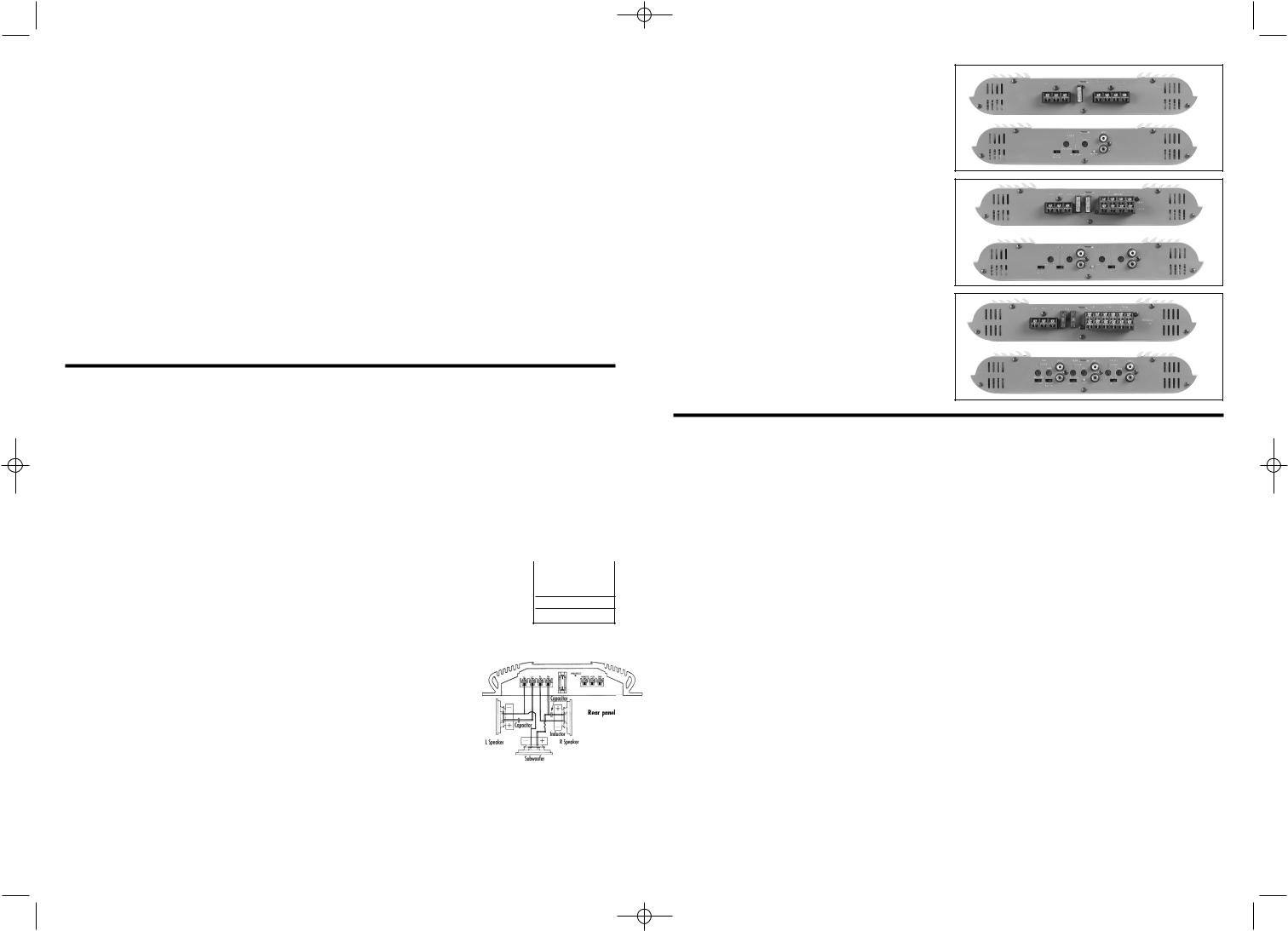
Hinweis: GTO 6000 im Brückenmodus betreiben |
||||
|
||||
auf keinen Fall außen am Wagen oder gar |
- |
|||
+ |
||||
im Motorraum installiert werden. |
Front R+ |
L- |
||
|
|
|||
Verwenden Sie den Verstärker als
Schablone und markieren Sie so die
Bohrlöcher dort, wo Sie ihn befestigen
wollen. Bohren Sie die entsprechenden Löcher und montieren Sie den Verstärker mit Blechschrauben. Überprüfen Sie, ob er auch sicher hält.
Stromversorgung anschließen
Die Abbildungen 1-3 zeigen die Anschlussverbindungen. Verwenden Sie einen Leitungsquerschnitt von mindes tens 6 mm2 für die Plusund Masseleitungen.
Entfernen Sie bei den Plus-,
Ferneinschaltund Masseleitungen etwa 1,5 cm der
FREQUENZ |
INDUKTIVITÄT |
KAPAZITÄT |
Übernahmefrequenz6 dB/Oktave LP (4 Ohm) |
6 dB/Oktave LP (4 |
|
Ohm) |
|
|
75Hz |
8.0mH |
530µF |
100Hz |
6.4mH |
400µF |
125Hz |
5.0mH |
318µF |
150Hz |
4.2mH |
265µF |
175Hz |
3.6mH |
227µF |
Isolierung. Sie können nun das blanke Kabel an den entsprechenden Anschlussklemmen des Verstärkers befestigen. Verlegen Sie eine Leitung vom Masseanschluss des Verstärkers (GND) zur nächstgelegenen blanken Chassisstelle in Ihrem Fahrzeug. Kratzen Sie notfalls den Lack ab, um eine blanke Metalloberfläche mit guter elektrischer Verbindung zu erhalten. Verbinden Sie als nächstes mit einem Kabel die Batterie-Klemme am Verstärker (BATT) mit dem Plus-Pol (+) der Autobatterie. Verlegen Sie das Kabel durch eine werksseitig eingebaute Kabelführung im brandgeschützten Kabelkanal. Sollte ein solcher Kabelkanal nicht vorhanden sein oder Sie kommen an diesen nicht ohne weiteres heran, sollten Sie eine entsprechende Kabelführung einbauen lassen. Nun müssen Sie die Sicherung einbauen – das Verbindungskabel zwischen Autobatterie und Sicherung darf höchstens 45 cm lang sein. Die Sicherung, die Sie einbauen, muss genau vom gleichen Typ sein wie jene, die in der Endstufe installiert ist. Im Falle eines Kurzschlusses bewährt diese Ihren Verstärker oder das Fahrzeug vor Schäden. Legen Sie eine Verbindungsleitung zwischen dem Anschluss „REM“ am Verstärker und dem Anschluss „REMOTE OUT“ oder „MOTORANTENNE“ beim Steuergerät Ihres Autos.
Lautsprecherkabel verlegen
Verbinden Sie die Lautsprecherkabel mit den Anschlussklemmen „Speaker Output“ am Verstärker. Achten
Sie dabei auch die richtige Polung. Die Gesamtimpedanz der
Fig.1 GTO 2000 angeschlossenen Lautsprecher darf 2 Ohm nicht unterschrei-
ten, wenn der Verstärker im Stereobetrieb arbeitet.
Sollten Sie den Verstärker in Brückenschaltung betreiben, verbinden Sie die Lautsprecherkabel mit den Anschlüssen „Bridged“. Achten Sie auch hier auf die richtige Polarität. Die Gesamtimpedanz darf in diesem Betriebsmodus 4 Ohm nicht unterschreiten.
Fig.2 |
GTO 4000 |
Fig.3 |
GTO 6000 |
Fehlerbehebung |
|
|
|
|
Problem |
Mögliche Ursache |
Abhilfe |
|
|
Kein Ton (Anzeige leuchtet) |
Lautsprecherkabel oder Cinch-Kabel sind nicht |
Überprüfen Sie Verbindungskabel, Steuergerät |
||
und |
|
|
|
|
|
angeschlossen; Lautsprecher oder Steuergerät defektLautsprecher |
|||
|
|
|
||
Kein Ton (Anzeige leuchtet nicht) |
Keine Spannung an den Anschlüssen „BATT“ oder |
Überprüfen Sie die Spannung an den |
||
Anschlussklemmen |
|
|
|
|
|
„REM“; schlechte Masseverbindung |
des Verstärkers mit einen Voltmeter. |
||
|
|
Stellen Sie fehlerhafte Verbindungen wieder |
||
her. |
|
|
|
|
|
|
|
||
Kein Ton (Anzeige leuchtet nicht) |
Die Schutzschaltung des Verstärkers hat angesprochen, |
Lösen Sie ein Lautsprecherkabel |
||
nach dem anderen, um |
|
|
|
|
|
möglicherweise wegen Überhitzung, Lautsprechern mit |
festzustellen, welcher |
||
Lautsprecher oder welches Kabel |
|
|
|
|
|
Kurzschluss oder Defekt, oder wegen defekter |
einen Kurzschluss hat oder defekt ist. |
||
|
|
|
|
|
Technische Daten |
GTO 2000 |
GTO 4000 |
GTO 6000 |
|
Maximale Ausgangsleistung: |
400 watts |
600 watts |
1100 watts |
|
Ausgangsleistung in Brückenschaltung; RMS, 4 Ohm: |
220 watts |
300 watts |
550 watts |
|
Ausgangsleistung an 2 Ohm (RMS): |
2 x 110 watts |
4 x 75 watts |
4 x 75/2 x |
|
125 watts |
|
|
|
|
Ausgangsleistung an 4 Ohm (RMS): |
2 x 75 watts |
4 x 50 watts |
4 x 50/2 x |
|
75 watts |
|
|
|
|
Klirrfaktor (THD): |
0.10% |
0.10% |
0.10% |
|
Signal-Rauschabstand (bewertet nach A): |
>92dB |
>92dB>92dB |
|
|
Frequenzbereich: |
10Hz-40kHz |
10Hz-40kHz |
10Hz-40kHz |
|
Aktive Frequenzweiche (stufenlos einstellbar): |
30-320Hz |
30-320Hz |
30-320Hz |
|
Einstellmöglichkeiten der Frequenzweiche: |
LP/HP/Aus |
LP/HP/Aus |
HP/Aus + |
|
LP/Aus |
|
|
|
|
Flankensteilheit des Filters: 12dB |
12dB |
12dB |
|
|
Eingangsempfindlichkeit: |
100mV-4V |
100mV-4V |
100mV-4V |
|
Bassanhebung: |
+6db bei 45Hz |
+6db bei 45Hz |
+6db bei 45Hz |
|
Maße (B x H x T): |
358 x 294 x 55 mm |
358 x 294 x 55 mm |
568 x 294 x 55 mm |
|
Gewicht: |
4 kg |
4 kg |
6 kg |
|
 Loading...