


Cinema 5000 Series Screen Channel Systems
User’s Guide
|
TABLE OF CONTENTS |
|
1. JBL 5000 SERIES................................................................................................................................ |
2 |
|
1.1 |
THANK YOU FOR PURCHASING............................................................................................................... |
2 |
2. SYSTEM CONFIGURATIONS.......................................................................................................... |
3 |
|
2.1 |
LOW FREQUENCY SECTION ................................................................................................................... |
3 |
2.2 MID FREQUENCY SECTION.................................................................................................................... |
4 |
|
2.3 HIGH FREQUENCY SECTION .................................................................................................................. |
4 |
|
3. SYSTEM SUPPORT MECHANISM - BRACKET ASSEMBLY ...................................................... |
6 |
|
3.1 |
ASSEMBLY INSTRUCTIONS .................................................................................................................... |
7 |
4. DIGITAL SYSTEM CONTROL ...................................................................................................... |
11 |
|
4.1 JBL DSC CONTROLLERS .................................................................................................................... |
11 |
|
4.2 DSC BLOCK DIAGRAM ....................................................................................................................... |
11 |
|
4.3 |
THREE CHANNEL CONFIGURATION (LEFT, CENTER, RIGHT)................................................................. |
12 |
4.4 |
FIVE CHANNEL CONFIGURATION (LEFT, LEFT-EXTRA, CENTER, RIGHT-EXTRA, RIGHT)........................ |
12 |
4.5 |
SUBWOOFER CHANNEL ....................................................................................................................... |
12 |
5. SYSTEM CONNECTIONS............................................................................................................... |
13 |
|
5.1 |
SYSTEM BLOCK DIAGRAMS ................................................................................................................. |
13 |
5.2 WIRE RECOMMENDATIONS.................................................................................................................. |
14 |
|
5.3 |
SPEAKER CONNECTIONS ..................................................................................................................... |
14 |
6. POWER AMPLIFIER REQUIREMENTS ...................................................................................... |
16 |
|
7. SPEAKER PLACEMENT ................................................................................................................ |
18 |
|
7.1 |
VERTICAL PLACEMENT....................................................................................................................... |
18 |
7.2 |
HORIZONTAL SPACING ....................................................................................................................... |
18 |
7.3 |
DISTANCE FROM SPEAKER TO SCREEN ................................................................................................. |
19 |
7.4 HORN ARRAY AIMING ........................................................................................................................ |
19 |
|
7.4.1 Vertical Plane............................................................................................................................. |
19 |
|
7.4.2 Horizontal Plane......................................................................................................................... |
19 |
|
7.5 |
BAFFLE LOADING ............................................................................................................................... |
20 |
7.6 FULL BAFFLE WALL ........................................................................................................................... |
20 |
|
8. SPECIFICATIONS ........................................................................................................................... |
22 |
|
8.1 |
5671 SCREEN CHANNEL SYSTEM ........................................................................................................ |
22 |
8.2 |
5672 SCREEN CHANNEL SYSTEM ........................................................................................................ |
23 |
8.3 |
5674 SCREEN CHANNEL SYSTEM ........................................................................................................ |
24 |
9. WARRANTY INFORMATION........................................................................................................ |
25 |
|
JBL Cinema 5000 Series - User’s Guide |
page 1 |
CE P/N 981-00040-00 |
C5KUG 1M 6/97 |

Cinema 5000 Series Screen Channel Systems
User’s Guide
1. JBL 5000 Series
1.1 Thank you for purchasing...
The Cinema 5000 Series Screen Channel systems represent the best of JBL loudspeaker technology for cinema screen channel applications. Each 5000 Series screen channel system is a three-way, tri-amplified design, intended to provide superior sound quality over many years of reliable service.
There are three models of 5000 Series Screen Channel systems. All three use the same low frequency, mid-range, and high frequency drivers. Each system is scaled for a different room size. Therefore, they only differ in the number of low frequency transducers and physical size of the mid and high frequency horns.
Each section of the 5000 Series Screen Channel system is optimized for the frequency range over which it operates. JBL Optimized Aperture horns and drivers provide ultra-low distortion reproduction for today’s demanding digital soundtracks.
Your 5000 Series screen channel system is shipped in two cartons. One carton contains the low frequency section, and the second carton contains the mid and high frequency horns, drivers, mounting bracket and hardware.
Please be sure to save this user’s manual as a reference guide in the event that this system is moved, reinstalled, or a change in ownership occurs.
JBL Cinema 5000 Series - User’s Guide |
page 2 |
CE P/N 981-00040-00 |
C5KUG 1M 6/97 |
Cinema 5000 Series Screen Channel Systems
User’s Guide
2. System Configurations
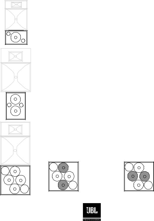
2.1 Low Frequency Section
The low frequency section of your system uses JBL 2226 Vented Gap Cooled low frequency drivers.
. |
. |
. |
. |
. |
|
|
. |
. |
. |
. |
. |
The 5671 Screen Channel system features the 5641 low frequency section, incorporating a single JBL 2226H 15” (380 mm) driver.
Connections are made to two screw type terminals located on the top of the enclosure.
The 5672 Screen Channel system features the 4648A low frequency section, incorporating two JBL 2226H 15” (380 mm) drivers.
Connections are made to two screw type terminals located on the rear of the enclosure.
The 5674 Screen Channel system features the 5644 low frequency section,
. |
. |
. |
. |
. |
|
|
. |
. |
. |
. |
. |
incorporating four JBL 2226H 15” (380 mm) drivers, in a unique DiamondQuad™ array. This array minimizes destructive driver interaction effects while maximizing output and pattern control.
Connections are made to four screw type terminals located on the top of the enclosure. Each driver pair is wired in parallel, resulting in two 4 ohm loads per enclosure.
VERTICAL |
HORIZONTAL |
pair wired in |
pair wired in |
parallel |
parallel |
JBL Cinema 5000 Series - User’s Guide |
page 3 |
CE P/N 981-00040-00 |
C5KUG 1M 6/97 |
Cinema 5000 Series Screen Channel Systems
User’s Guide
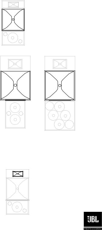
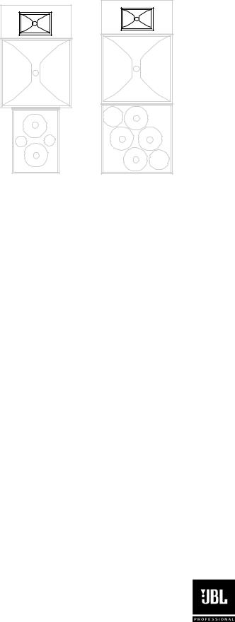
2.2 Mid Frequency Section
The mid frequency section on all systems feature Optimized Aperture horn/driver technology for the lowest possible distortion. The 2392 or 2392-S midrange Optimized Aperture horns provides outstanding midrange pattern control. The 2490H midrange compression driver has a 4” voice coil and titanium diaphragm with a 3” exit, and is optimized for response between 250 Hz and 4000 Hz.
The 5671 Screen Channel system features the 2392-S 30” horn, which is smaller in vertical and horizontal dimension to fit within the profile of the low frequency section, while maintaining midrange pattern control for smaller rooms.
. |
. |
. |
. |
. |
|
|
. |
. |
. |
. |
. |
. |
. |
. |
. |
. |
|
|
. |
. |
. |
. |
. |
The 5672 and 5674 Screen Channel systems both feature the 2392 44” horn, which maintains midrange pattern control for the largest rooms.
2.3 High Frequency Section
The high frequency section on all systems incorporate Optimized Aperture™ horn/driver technology for the lowest possible distortion. The HF driver is the JBL 2451H high frequency compression driver with neodymium-magnet structure. The 2451H is our most advanced compression driver, using our unique radial-ribbed 4” diaphragm and edgewound voice coil.
The 5671 Screen Channel system uses the 2332 90°x 40° horn, mounted in a 3/8” plywood baffle board. The width of the baffle matches the width of the LF section and HF horn to make baffle wall installation easier.
JBL Cinema 5000 Series - User’s Guide |
page 4 |
CE P/N 981-00040-00 |
C5KUG 1M 6/97 |
Cinema 5000 Series Screen Channel Systems
User’s Guide
. |
. |
. |
. |
. |
|
|
. |
. |
. |
. |
. |
. |
. |
. |
. |
. |
|
|
. |
. |
. |
. |
. |
The 5672 and 5674 Screen Channel systems both use the 2352 90°x 40° horn, mounted in a 3/8” plywood baffle board. The width of the baffle matches the width of the MF horn to make baffle wall installation easier.
JBL Cinema 5000 Series - User’s Guide |
page 5 |
CE P/N 981-00040-00 |
C5KUG 1M 6/97 |
Cinema 5000 Series Screen Channel Systems
User’s Guide
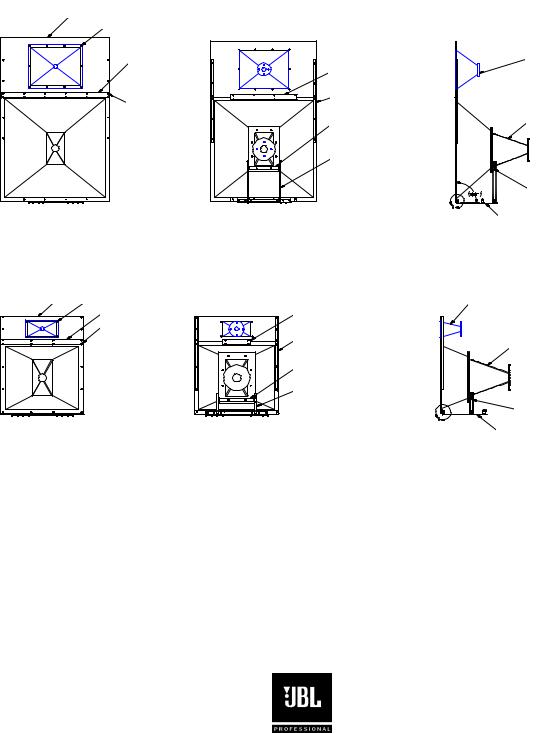
3. System Support Mechanism - Bracket Assembly
The horn array bracket supplied with your 5000 Series Screen channel systems provides a simple way to mount and install the mid and high frequency horns and drivers on top of the low frequency section.
For the 5672 and 5674 systems, the bracket assemblies are identical -- model number HB74.
The 5671 system is shipped with a smaller version bracket with identical functions and features -- model number HB71.
baffle board 


 2352 HF horn
front strap |
screw through |
baffle board, into |
C-channel upright |
rail |
|
2352 |
|
back strap |
HF horn |
|
|
||
upright rails |
|
|
(“C” channel) |
|
|
yoke |
throat |
|
section |
||
(connects to throat section) |
||
upright supports |
|
|
(tilt adjustment bar) |
|
pre -set tilt positions
mounting plate
Front, rear, and side views of 5672/5674 bracket assembly
baffle board 2332 HF horn |
|
2332 |
|
front strap |
back strap |
HF horn |
|
|
|||
screw through |
upright rails |
throat |
|
baffle board, |
|||
(“C” channel) |
section |
||
into upright rail |
|||
|
yoke |
|
|
|
(connects to throat section) |
|
|
|
upright supports |
pre-set tilt |
|
|
(tilt adjustment bar) |
||
|
|
positions |
|
|
|
mounting |
|
|
|
plate |
Front, rear, and side views of 5671 bracket assembly
Once assembled, the horn array is adjusted for proper tilt angle using one of the available tilt angle holes, which are located on the upright rail sections of the bracket assembly. Each hole represents an increment of 2.5 degrees forward tilt. A maximum of 10 degrees forward tilt can be safely achieved without risk of exceeding the array’s center of gravity.
Ten degrees of tilt should be the maximum required for today’s cinema designs, however the specific tilt angle depends on the room dimensions and floor slope of the seating area.
See section 7.4, “Horn Array Aiming”, for more information on proper aiming once assembly is complete and ready for installation.
JBL Cinema 5000 Series - User’s Guide |
page 6 |
CE P/N 981-00040-00 |
C5KUG 1M 6/97 |

Cinema 5000 Series Screen Channel Systems
User’s Guide
In the carton containing the midrange and high frequency components, you should find the following items:
∙Steel mounting plate
∙Steel L-channel with hinges
∙Upright supports for tilt adjustment (2)
∙Yoke
∙Horn baffle board
∙Upright rail C-channels (2)
∙Front strap
∙Back strap
∙Hardware for assembly
count item
(34)* 1/4-20 x 7/8 large button head, Philips screw, black (*5671 kit includes 24 pcs)
(34)* 1/4 spring lock washer, regular, black (*5671 kit includes 24 pcs.)
(44)* 1/4 flat washer, type A, black (*5671 kit includes 34 pcs.)
(10)1/4-20 hex nut
(4)5/16-18 x 5/8 large button head, Philips, black
(4)5/16 spring lock washer, type A
(8)5/16 flat washer, type A
(4)5/16-18 hex nut
(6)#12-24 x 5/8 large button head, Philips screw
(8)#12 flat washer, type A
(6)#12 spring lock washer, regular
(6)#12-24 hex nut
3.1Assembly Instructions
STEP 1.
Make sure you have all of the pieces listed above. If items are missing, please contact your JBL Professional Representative immediately, or call JBL Professional at (818) 894-8850, ask for Customer Service & Parts. Outside the United States, please contact your JBL Professional Authorized Distributor.
JBL Cinema 5000 Series - User’s Guide |
page 7 |
CE P/N 981-00040-00 |
C5KUG 1M 6/97 |
 Loading...