

3261 Jaguar XJ6
Models covered
Jaguar XJ6 models with 3.2 litre (3239 cc), 3.6 litre (3590 cc) & 4.0 litre (3980 cc)
six-cylinder in-line dohc petrol engines and automatic transmission
Covers most features of Daimler 3.6 and 4.0 litre models
Does not cover 2.9 litre (2919 cc) sohc engine or manual transmission
Does not cover XJR models or revised Jaguar/Daimler model ranges introduced September 1994
Jaguar XJ6
Service and Repair Manual
Mike Stubblefield
© Haynes Publishing 1997
A book in the Haynes Service and Repair Manual Series
All rights reserved. No part of this book may be reproduced or transmitted
in any form or by any means, electronic or mechanical, including
photocopying, recording or by any information storage or retrieval system,
without permission in writing from the copyright holder.
ISBN 1 85960 261 4
British Library Cataloguing in Publication Data
A catalogue record for this book is available from the British Library.
Printed by J H Haynes & Co. Ltd, Sparkford, Nr Yeovil,
Somerset BA22 7JJ
Haynes Publishing
Sparkford, Nr Yeovil, Somerset BA22 7JJ, England
Haynes North America, Inc
861 Lawrence Drive, Newbury Park, California 91320, USA
Editions Haynes S.A.
147/149, rue Saint Honoré, 75001 PARIS, France
Haynes Publishing Nordiska AB
Fyrisborgsgatan 5, 754 50 Uppsala, Sverige
ABCDE
FGHIJ
KLMNO
PQRST
1 2 3
(3261-248-11AA1)

3261 Jaguar XJ6
LIVING WITH YOUR JAGUAR XJ6
Introduction Page 0•4
Notes for UK readers Page 0•4
Safety first! Page 0•5
Roadside repairs
Introduction Page 0•6
If your car won’t start Page 0•6
Jump starting Page 0•7
Wheel changing Page 0•8
Identifying leaks Page 0•9
Towing Page 0•9
Weekly checks
Introduction Page 0•10
Underbonnet check points Page 0•10
Engine oil level Page 0•11
Coolant level Page 0•11
Brake fluid level Page 0•12
Screen washer fluid level Page 0•12
Power steering fluid level Page 0•13
Wiper blades Page 0•13
Tyre condition and pressure Page 0•14
Battery Page 0•15
Bulbs and fuses Page 0•15
Lubricants, fluids and tyre pressures Page 0•16
MAINTENANCE
Routine maintenance and servicing Page 1•1
Servicing specifications Page 1•2
Maintenance schedule Page 1•3
Maintenance procedures Page 1•6
Contents

3261 Jaguar XJ6
REPAIRS & OVERHAUL
Engine and associated systems
Engine in-car repair procedures Page 2A•1
Engine removal and overhaul procedures Page 2B•1
Cooling, heating and air conditioning systems Page 3•1
Fuel and exhaust systems Page 4•1
Engine electrical systems Page 5•1
Emissions and engine cone control systems Page 6•1
Transmission
Automatic transmission Page 7•1
Drivetrain Page 8•1
Brakes and suspension
Braking system Page 9•1
Suspension and steering systems Page 10•1
Body equipment
Bodywork and fittings Page 11•1
Body electrical systems Page 12•1
Wiring diagrams Page 12•16
REFERENCE
Dimensions and weights Page REF•1
Jacking and vehicle support Page REF•1
Radio/cassette unit anti-theft system - precaution Page REF•1
Conversion factors Page REF•2
Use of English Page REF•3
Buying spare parts and vehicle identification Page REF•4
General repair procedures Page REF•5
Tools and working facilities Page REF•6
MOT test checks Page REF•8
Fault finding Page REF•12
Glossary of technical terms Page REF•18
Index Page REF•22
Contents

These models are equipped with dual overhead cam in-line sixcylinder engines. The engines feature a computer-controlled ignition
system and electronic fuel injection. Transmissions are a four-speed
automatic equipped with a lock-up torque converter. The transmission
is mounted to the back of the engine, and power is transmitted to the
fully independent rear axle through a two-piece propshaft. The
differential is bolted solidly to a frame crossmember and drives the
wheels through driveshafts equipped with inner and outer U-joints.
The front suspension is fitted with upper and lower control arms, coil
springs and shock absorbers. The rear suspension is an independent
type suspension which also have coil spring/shock absorber
assemblies and a lower control arm. The rear driveshaft acts as the
upper control arm.
Power-assisted Anti-lock Brake Systems (ABS) with four-wheel disc
brakes are standard equipment on all Jaguar XJ6 models covered in
this manual. Power rack-and-pinion steering is also standard
equipment.
Your Jaguar manual
The aim of this manual is to help you get the best value from your
vehicle. It can do so in several ways. It can help you decide what work
must be done (even should you choose to get it done by a garage). It
will also provide information on routine maintenance and servicing, and
give a logical course of action and diagnosis when random faults
occur. However, it is hoped that you will use the manual by tackling the
work yourself. On simpler jobs it may even be quicker than booking the
car into a garage and going there twice, to leave and collect it. Perhaps
most important, a lot of money can be saved by avoiding the costs a
garage must charge to cover its labour and overheads.
The manual has drawings and descriptions to show the function of
the various components so that their layout can be understood. Tasks
are described and photographed in a clear step-by-step sequence.
Notes for UK readers
Because this manual was originally written in the US, its layout
differs from our UK-originated manuals. The preliminary and reference
sections have been re-written specifically for the UK market, and the
maintenance schedule has been amended to suit UK vehicles.
However, it will be noticed that some references to components
remain in the US style; the UK equivalent of US components and
various other US words is given in the Section headed “Use of
English”. It should be remembered that the project vehicle used in the
main Chapters of this manual was a left-hand drive US model;
therefore, the position of the steering wheel, steering column and
pedals, etc. will be on the opposite side of the vehicle on UK models.
References to “right” and “left” will need to be considered carefully to
decide which applies to UK models (eg the headlight dipped beams
should be adjusted to dip to the left of the headlight vertical line
described in Chapter 12, instead of to the right on US models). In other
instances, no reference is made to the location of a particular item, but
that item may be located on the opposite side of the vehicle on UK
models. Reference to the underbonnet photos at the start of Chapter 1
will give the reader the location of the engine compartment
components on UK models.
All specifications in the main Chapters of the manual appear in
Imperial form; the equivalent metric values can be calculated using the
“Conversion factors” page.
The only other major difference between UK and US models is in the
level of emission control equipment fitted to the vehicle. To meet the
strict emission standards present in the US, all vehicles for that market
are fitted with various emission control systems (see Chapter 6), most
of which are not fitted to the corresponding UK model, especially so on
early models. Therefore, a lot of the information contained in Chapter 6
is not applicable to UK models.
Acknowledgements
Thanks are due to Jean Preis, Rich Wilson and Ray Marcuse of
Silver Star Jaguar (Thousand Oaks, CA), Rick Calaci of Conejo Imports
(Newbury Park, CA) and Jim Strohmeier and Jonathan Lund of British
Motor Cars (Thousand Oaks, CA), for providing valuable technical
information. Technical writers who contributed to this project include
Jeff Kibler, Robert Maddox and Jay Storer.
We take great pride in the accuracy of information given in this
manual, but vehicle manufacturers make alterations and design
changes during the production run of a particular vehicle of which
they do not inform us. No liability can be accepted by the authors
or publishers for loss, damage or injury caused by any errors in, or
omissions from, the information given.
0•4 Introduction
3261 Jaguar XJ6
Haynes mechanic, author and photographer with 1989 Jaguar XJ6

3261 Jaguar XJ6
Safety first! 0•5
Working on your car can be dangerous.
This page shows just some of the potential
risks and hazards, with the aim of creating a
safety-conscious attitude.
General hazards
Scalding
• Don’t remove the radiator or expansion
tank cap while the engine is hot.
• Engine oil, automatic transmission fluid or
power steering fluid may also be dangerously
hot if the engine has recently been running.
Burning
• Beware of burns from the exhaust system
and from any part of the engine. Brake discs
and drums can also be extremely hot
immediately after use.
Crushing
• When working under or near
a raised vehicle,
always
supplement the
jack with axle
stands, or use
drive-on
ramps.
Never
venture
under a car which
is only supported by a jack.
• Take care if loosening or tightening hightorque nuts when the vehicle is on stands.
Initial loosening and final tightening should
be done with the wheels on the ground.
Fire
• Fuel is highly flammable; fuel vapour is
explosive.
• Don’t let fuel spill onto a hot engine.
• Do not smoke or allow naked lights
(including pilot lights) anywhere near a
vehicle being worked on. Also beware of
creating sparks
(electrically or by use of tools).
• Fuel vapour is heavier than air, so don’t
work on the fuel system with the vehicle over
an inspection pit.
• Another cause of fire is an electrical
overload or short-circuit. Take care when
repairing or modifying the vehicle wiring.
• Keep a fire extinguisher handy, of a type
suitable for use on fuel and electrical fires.
Electric shock
• Ignition HT
voltage can be
dangerous,
especially to
people with heart
problems or a
pacemaker. Don’t
work on or near the
ignition system with
the engine running or
the ignition switched on.
• Mains voltage is also dangerous. Make
sure that any mains-operated equipment is
correctly earthed. Mains power points should
be protected by a residual current device
(RCD) circuit breaker.
Fume or gas intoxication
• Exhaust fumes are
poisonous; they often
contain carbon
monoxide, which is
rapidly fatal if inhaled.
Never run the
engine in a
confined space
such as a garage
with the doors shut.
• Fuel vapour is also
poisonous, as are the vapours from some
cleaning solvents and paint thinners.
Poisonous or irritant substances
• Avoid skin contact with battery acid and
with any fuel, fluid or lubricant, especially
antifreeze, brake hydraulic fluid and Diesel
fuel. Don’t syphon them by mouth. If such a
substance is swallowed or gets into the eyes,
seek medical advice.
• Prolonged contact with used engine oil can
cause skin cancer. Wear gloves or use a
barrier cream if necessary. Change out of oilsoaked clothes and do not keep oily rags in
your pocket.
• Air conditioning refrigerant forms a
poisonous gas if exposed to a naked flame
(including a cigarette). It can also cause skin
burns on contact.
Asbestos
• Asbestos dust can cause cancer if inhaled
or swallowed. Asbestos may be found in
gaskets and in brake and clutch linings.
When dealing with such components it is
safest to assume that they contain asbestos.
Special hazards
Hydrofluoric acid
• This extremely corrosive acid is formed
when certain types of synthetic rubber, found
in some O-rings, oil seals, fuel hoses etc, are
exposed to temperatures above 4000C. The
rubber changes into a charred or sticky
substance containing the acid. Once formed,
the acid remains dangerous for years. If it
gets onto the skin, it may be necessary to
amputate the limb concerned.
• When dealing with a vehicle which has
suffered a fire, or with components salvaged
from such a vehicle, wear protective gloves
and discard them after use.
The battery
• Batteries contain sulphuric acid, which
attacks clothing, eyes and skin. Take care
when topping-up or carrying the battery.
• The hydrogen gas given off by the battery
is highly explosive. Never cause a spark or
allow a naked light nearby. Be careful when
connecting and disconnecting battery
chargers or jump leads.
Air bags
• Air bags can cause injury if they go off
accidentally. Take care when removing the
steering wheel and/or facia. Special storage
instructions may apply.
Diesel injection equipment
• Diesel injection pumps supply fuel at very
high pressure. Take care when working on
the fuel injectors and fuel pipes.
Warning: Never expose the hands,
face or any other part of the body
to injector spray; the fuel can
penetrate the skin with potentially fatal
results.
Remember...
DO
• Do use eye protection when using power
tools, and when working under the vehicle.
• Do wear gloves or use barrier cream to
protect your hands when necessary.
• Do get someone to check periodically
that all is well when working alone on the
vehicle.
• Do keep loose clothing and long hair well
out of the way of moving mechanical parts.
• Do remove rings, wristwatch etc, before
working on the vehicle – especially the
electrical system.
• Do ensure that any lifting or jacking
equipment has a safe working load rating
adequate for the job.
A few tips
DON’T
• Don’t attempt to lift a heavy component
which may be beyond your capability – get
assistance.
• Don’t rush to finish a job, or take
unverified short cuts.
• Don’t use ill-fitting tools which may slip
and cause injury.
• Don’t leave tools or parts lying around
where someone can trip over them. Mop
up oil and fuel spills at once.
• Don’t allow children or pets to play in or
near a vehicle being worked on.
3261 Jaguar XJ6
0•6 Roadside repairs
The following pages are intended to help in dealing with
common roadside emergencies and breakdowns. You will find
more detailed fault finding information at the back of the
manual, and repair information in the main chapters.
If your car won’t start
and the starter motor
doesn’t turn
M If it’s a model with automatic transmission, make sure the
selector is in ‘P’ or ‘N’.
M Open the bonnet and make sure that the battery terminals
are clean and tight.
M Switch on the headlights and try to start the engine. If the
headlights go very dim when you’re trying to start, the
battery is probably flat. Get out of trouble by jump starting
(see next page) using a friend’s car.
If your car won’t start
even though the starter
motor turns as normal
M Is there fuel in the tank?
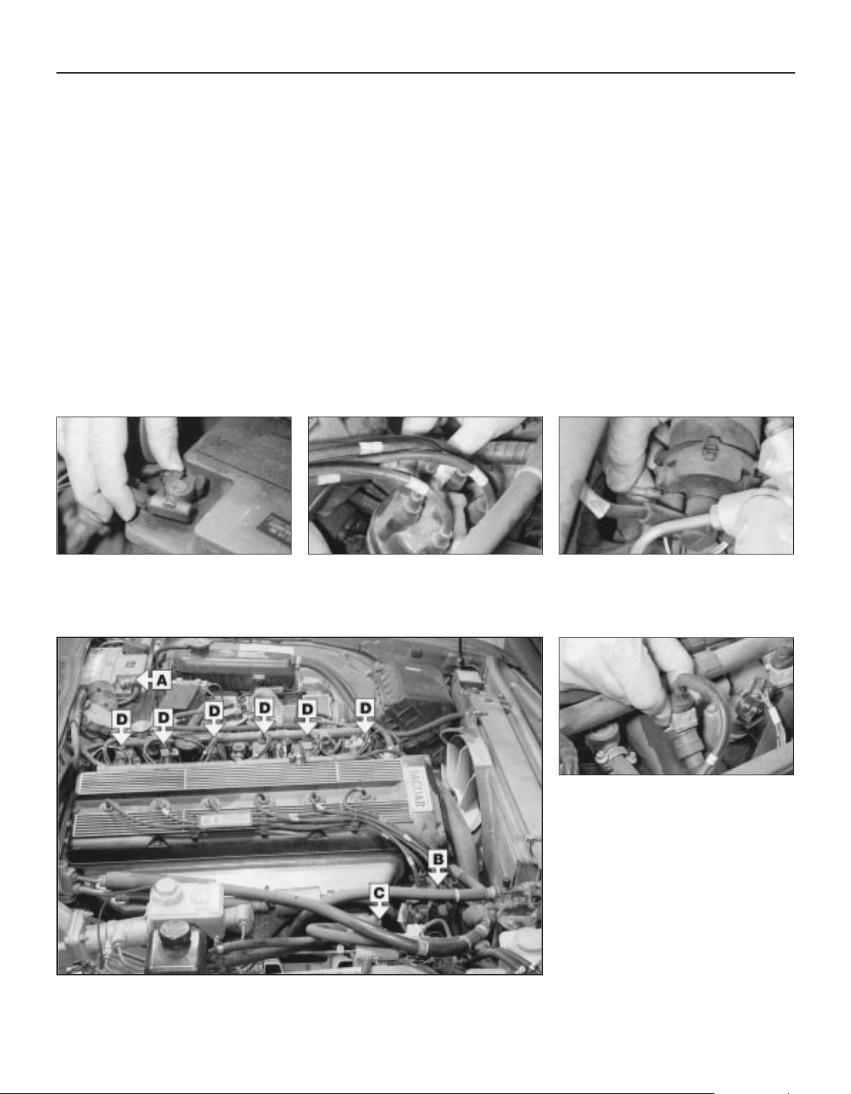
M Is there moisture on electrical components under the
bonnet? Switch off the ignition, then wipe off any obvious
dampness with a dry cloth. Spray a water-repellent aerosol
product (WD-40 or equivalent) on ignition and fuel system
electrical connectors like those shown in the photos.
Pay special attention to the ignition coil wiring connector
and HT leads.
Check the condition and security of the
battery connections.
A
Check that the spark plug HT leads are
securely connected by pushing them onto
the plugs and distributorery connections.
B
Check that the HT leads and wiring
connectors are securely connected to
the ignition coil.
C
Check that the wiring connectors are
securely connected to the injectors and
various fuel system sensors and switches.
D
Check that electrical connections are secure (with the ignition switched off) and spray them
with a water dispersant spray like WD40 if you suspect a problem due to damp
3261 Jaguar XJ6
Roadside repairs 0•7
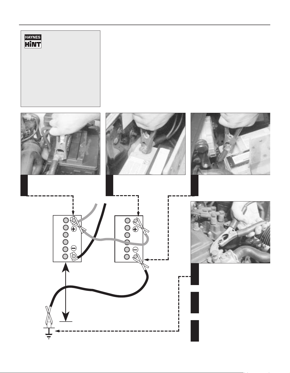
When jump-starting a car using a
booster battery, observe the following
precautions:
4 Before connecting the booster
battery, make sure that the ignition
is switched off.
4 Ensure that all electrical equipment
(lights, heater, wipers, etc) is
switched off.
4 Take note of any special precautions
printed on the battery case.
4 Make sure that the booster battery
is the same voltage as the
discharged one in the vehicle.
4 If the battery is being jump-started
from the battery in another vehicle,
the two vehicles MUST NOT TOUCH
each other.
4 Make sure that the transmission is in
neutral (or PARK, in the case of
automatic transmission).
Jump starting will get you
out of trouble, but you must
correct whatever made the
battery go flat in the first
place. There are three possibilities:
1) The battery has been drained by
repeated attempts to start, or by
leaving the lights on.
2) The charging system is not working
properly (alternator drivebelt slack or
broken, alternator wiring fault or
alternator itself faulty).
3) The battery itself is at fault (electrolyte
low, or battery worn out).
Connect one end of the red jump lead
to the positive (+) terminal of the flat
battery
Connect the other end of the red lead
to the positive (+) terminal of the
booster battery
Connect one end of the black jump lead
to the negative (-) terminal of the
booster battery
Connect the other end of the black
jump lead to a bolt or bracket on the
engine block, well away from the
battery, on the vehicle to be started
1 2 3
4
Make sure that the jump leads will not
come into contact with the fan,
drivebelts or other moving parts of the
engine
5
Start the engine using the booster
battery, then with the engine running at
idle speed, disconnect the jump leads
in the reverse order of connection
6
Jump starting
3261 Jaguar XJ6
0•8 Roadside repairs
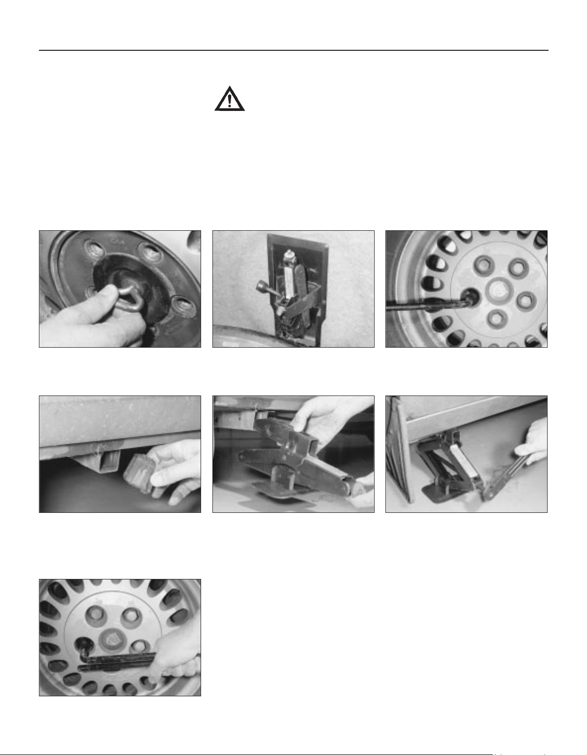
The spare wheel and tools are stored in
the boot. Remove the carpet cover then
unscrew the retainer and lift out the spare
wheel from the boot.
Wheel changing
Some of the details shown here will vary
according to model. For instance, the location
of the spare wheel and jack is not the same
on all cars. However, the basic principles
apply to all vehicles.
Warning: Do not change a wheel in a situation where you risk being hit by
other traffic. On busy roads, try to stop in a lay-by or a gateway. Be wary of
passing traffic while changing the wheel – it is easy to become distracted by
the job in hand.
Finally...
M Remove the wheel chocks.
M
Check the tyre pressure on the wheel just
fitted. If it is low, or if you don’t have a
pressure gauge with you, drive slowly to
the nearest garage and inflate the tyre to
the right pressure.
M Have the damaged tyre or wheel repaired
as soon as possible.
Remove the plastic cover from the end of
the vehicle jack lifting point tube, nearest
to the wheel that is being changed.
Slide the lifting bracket of the jack fully
into the lifting point tube. Make sure the
jack is located on firm ground.
Raise the jack until the wheel is raised
clear of the ground. Unscrew the wheel
nuts and remove the wheel. Fit the spare
wheel and screw on the nuts. Lightly tighten
the nuts then lower the vehicle to the ground.
With the vehicle on the ground, remove
the trim cap (where fitted) and slacken
each wheel nut by half a turn.
Remove the jack and wheelbrace its
holder which is located behind the spare
wheel.
1
2
3
4
Securely tighten the wheel nuts in a
diagonal sequence then (where necessary)
refit the wheel trim cap. Stow the tolls and
punctured wheel and back in the luggage
compartment and secure them in position.
Note that the wheel nuts should be slackened
and retightened to the specified torque at the
earliest possible opportunity.
7
5
6
Preparation
M When a puncture occurs, stop as soon as
it is safe to do so.
M Park on firm level ground, if possible,
and well out of the way of other traffic.
M Use hazard warning lights if necessary.
M If you have one, use a warning triangle to
alert other drivers of your presence.
M Apply the handbrake and engage first or
reverse gear (or Park on models with
automatic transmission.
M Chock the wheel diagonally opposite the
one being removed – a couple of large
stones will do for this.
M If the ground is soft, use a flat piece of
wood to spread the load under the jack.
Changing the wheel
3261 Jaguar XJ6
Roadside repairs 0•9
When all else fails, you may find yourself
having to get a tow home – or of course you
may be helping somebody else. Long-distance
recovery should only be done by a garage or
breakdown service. For shorter distances, DIY
towing using another car is easy enough, but
observe the following points:
M Use a proper tow-rope – they are not
expensive. The vehicle being towed must
display an ‘ON TOW’ sign in its rear window.
M Always turn the ignition key to the ‘on’
position when the vehicle is being towed, so
that the steering lock is released, and that the
direction indicator and brake lights will work.
M Only attach the tow-rope to the towing
eyes provided. On some models with energyabsorbing bumpers there are no front towing
eyes; on these vehicles the tow-rope should
be attached around the rear arm of the lower
control arm so that the rope passes on the
inside of the coil spring.
M Before being towed, release the handbrake
and select neutral on the transmission.
M Note that greater-than-usual pedal
pressure will be required to operate the
brakes, since the vacuum servo unit is only
operational with the engine running.
M On models with power steering, greaterthan-usual steering effort will also be required.
M The driver of the car being towed must
keep the tow-rope taut at all times to avoid
snatching.
M Make sure that both drivers know the route
before setting off.
M Only drive at moderate speeds and keep
the distance towed to a minimum. Drive
smoothly and allow plenty of time for slowing
down at junctions.
M On models with automatic transmission,
special precautions apply. If in doubt, do not
tow, or transmission damage may result.
Caution: On models with automatic
transmission, if the vehicle is to be towed
with its rear wheels on the ground, and
extra 1.7 litres of fluid should be added to
the transmission, prior to towing (this extra
fluid must be drained before driving the
vehicle). Even with the extra fluid added to
the transmission, do not tow the vehicle at
speeds in excess of 30 mph (50 kmh) or for
a distance of greater than 15 miles (25 km).
If towing speed/distance are to exceed
these limits, then the vehicle must be
towed with its rear wheels off the ground.
Towing
Puddles on the garage floor or drive, or
obvious wetness under the bonnet or
underneath the car, suggest a leak that needs
investigating. It can sometimes be difficult to
decide where the leak is coming from,
especially if the engine bay is very dirty
already. Leaking oil or fluid can also be blown
rearwards by the passage of air under the car,
giving a false impression of where the
problem lies.
Warning: Most automotive oils
and fluids are poisonous. Wash
them off skin, and change out of
contaminated clothing, without
delay.
The smell of a fluid leaking
from the car may provide a
clue to what’s leaking. Some
fluids are distinctively
coloured. It may help to clean the car and
to park it over some clean paper as an
aid to locating the source of the leak.
Remember that some leaks may only
occur while the engine is running.
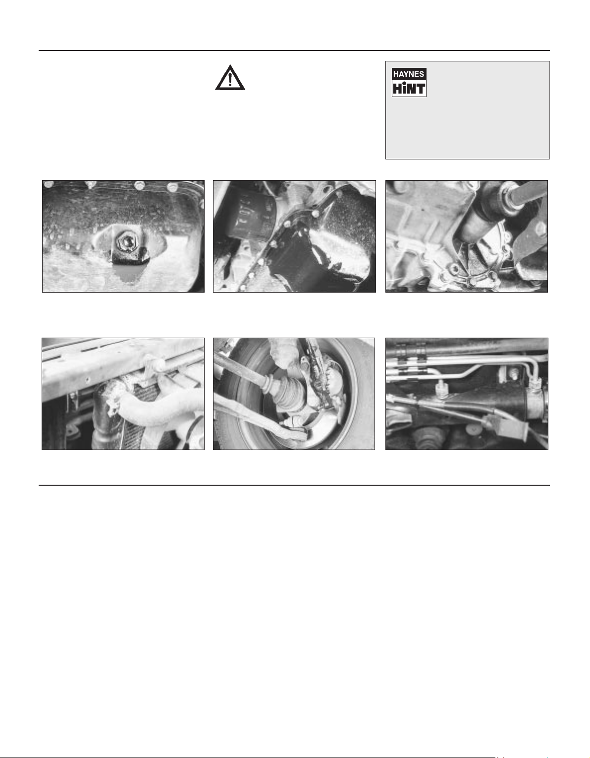
Sump oil Gearbox oil
Brake fluid
Power steering fluid
Oil from filter
Antifreeze
Engine oil may leak from the drain plug... ...or from the base of the oil filter.
Leaking antifreeze often leaves a crystalline
deposit like this.
Gearbox oil can leak from the seals at the
inboard ends of the driveshafts.
A leak occurring at a wheel is almost
certainly brake fluid.
Power steering fluid may leak from the pipe
connectors on the steering rack.
3261 Jaguar XJ6
0•10 Weekly checks
There are some very simple checks which
need only take a few minutes to carry out, but
which could save you a lot of inconvenience
and expense.
These "Weekly checks" require no great skill
or special tools, and the small amount of time
they take to perform could prove to be very
well spent, for example;
M Keeping an eye on tyre condition and
pressures, will not only help to stop them
wearing out prematurely, but could also save
your life.
M
Many breakdowns are caused by electrical
problems. Battery-related faults are particularly
common, and a quick check on a regular basis
will often prevent the majority of
these.
M If your car develops a brake fluid leak, the
first time you might know about it is when
your brakes don't work properly. Checking
the level regularly will give advance warning of
this kind of problem.
M If the oil or coolant levels run low, the cost
of repairing any engine damage will be far
greater than fixing the leak, for example.
Introduction
§
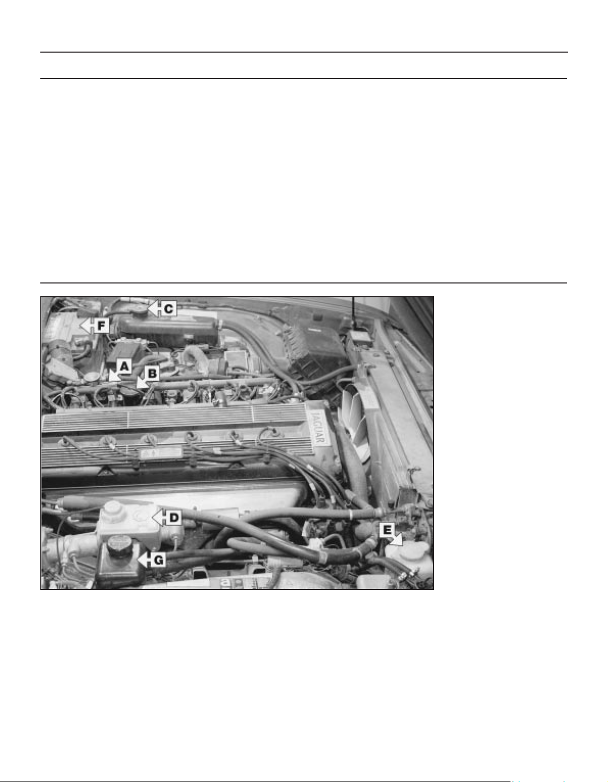
3.6 litre engine
(others similar)
Viewed from right-hand side
A
Engine oil level dipstick
B
Engine oil filler cap
C
Coolant expansion tank
D
Brake fluid reservoir
E
Screen washer fluid reservoir
F
Battery
G
Power steering fluid reservoir
Underbonnet check points
3261 Jaguar XJ6
Weekly checks 0•11
Engine oil level
Before you start
4 Make sure that your car is on level ground.
4 Check the oil level before the car is driven,
or at least 5 minutes after the engine has been
switched off.
The correct oil
Modern engines place great demands on their
oil. It is very important that the correct oil for
your car is used (See “Lubricants, fluids and
tyre pressures”).
Car care
l If you have to add oil frequently, you should
check whether you have any oil leaks. Place
some clean paper under the car overnight,
and check for stains in the morning. If there
are no leaks, the engine may be burning oil
(see “Fault finding”).
l Always maintain the level between the
upper and lower dipstick marks (see photo 3).
If the level is too low severe engine damage
may occur. Oil seal failure may result if the
engine is overfilled by adding too much oil.
If the oil level is checked
immediately after driving the
vehicle, some of the oil will
remain in the upper engine
components, resulting in an inaccurate
reading on the dipstick!
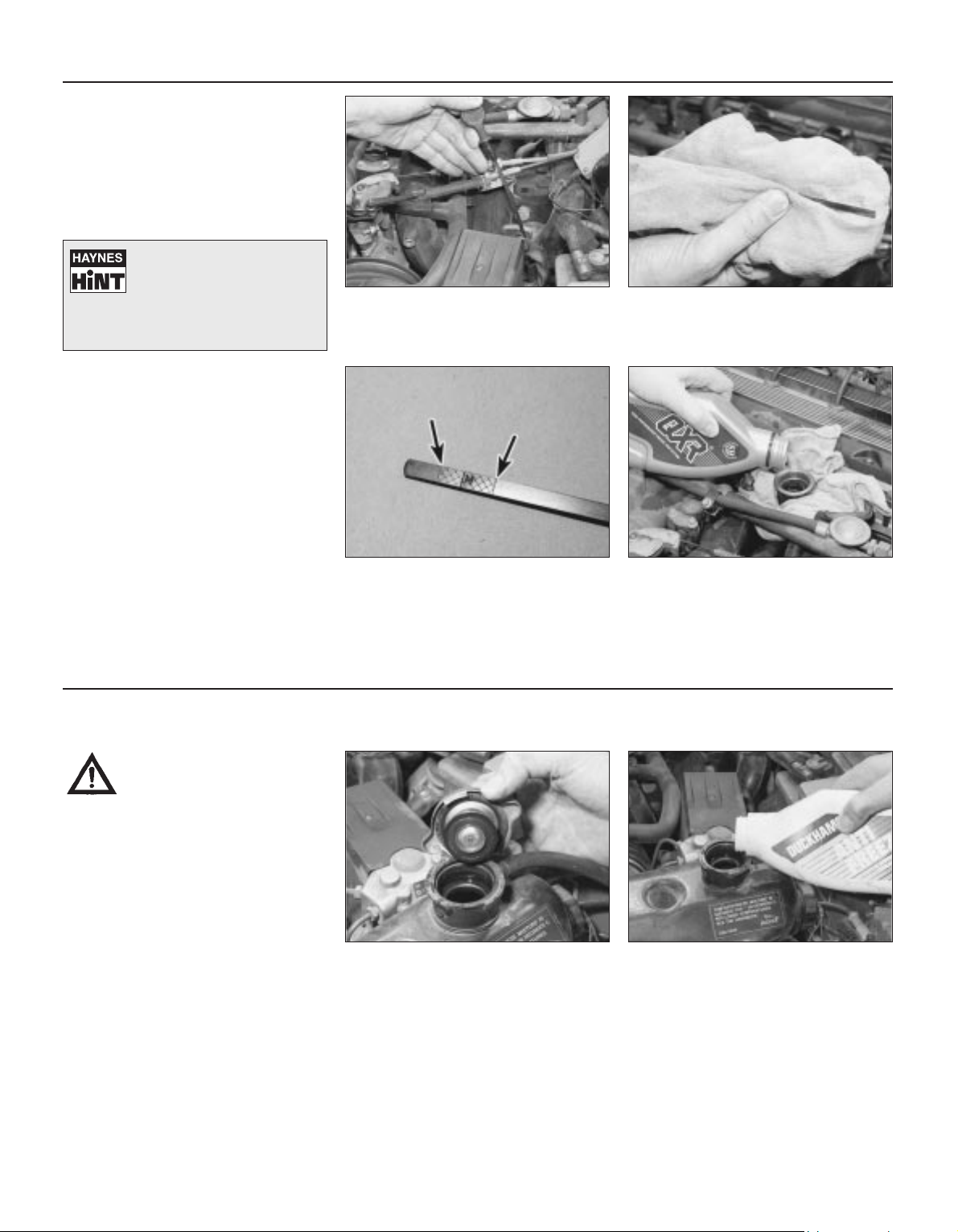
The dipstick is located at the rear of the
engine on the left-hand side (see “Underbonnet check points” on page 0•10 for
exact location). Withdraw the dipstick.
Using a clean rag or paper towel remove
all oil from the dipstick. Insert the clean
dipstick into the tube as far as it will go,
then withdraw it again.
Note the oil level on the end of the
dipstick which should be between the
upper and lower marks. The “M” mark is
for use when checking the oil level after the
vehicle has been standing overnight; in this
case the oil level should be between the “M”
and upper level markings.
Oil is added through the filler cap.
Unscrew the cap and top-up the level; a
funnel may help to reduce spillage. Add
the oil slowly, checking the level on the dipstick
often. Don’t overfill (see “Car care” left).
1
2
34
Warning: DO NOT attempt to
remove the expansion tank
pressure cap when the engine
is hot, as there is a very great
risk of scalding. Do not leave
open containers of coolant
about, as it is poisonous.
Car care
l Adding coolant should not be necessary on
a regular basis. If frequent topping-up is
required, it is likely there is a leak. Check the
radiator, all hoses and joint faces for signs of
staining or wetness, and rectify as necessary.
l It is important that antifreeze is used in the
cooling system all year round, not just during
the winter months. Don’t top-up with water
alone, as the antifreeze will become too
diluted.
Coolant level
The coolant level should be checked only
with the engine cold. The level is checked
in the expansion tank on the left-hand
side of the engine compartment. Remove the
expansion tank pressure cap and check that
the coolant level is upto the base of filler neck.
If topping up is necessary, add a mixture
of water and antifreeze to the expansion
tank until the coolant level is upto the
base of the filler neck. Once the level is
correct, securely refit the pressure cap.
1
2
3261 Jaguar XJ6
0•12 Weekly checks
Brake fluid level
Warning:
l Brake fluid can harm your
eyes and will damage painted
surfaces, so use extreme caution
when handling and pouring it.
l Do not use fluid that has
been standing open for some
time, as it absorbs moisture
from the air, which can cause a
dangerous loss of braking
effectiveness.
Safety first!
l If the reservoir requires repeated toppingup this is an indication of a fluid leak
somewhere in the system, which should be
investigated immediately.
l If a leak is suspected, the car should not be
driven until the braking system has been
checked. Never take any risks where brakes
are concerned.
• Make sure that your car is
on level ground.
• The fluid level in the
reservoir will drop slightly as
the brake pads wear down, but the fluid
level must never be allowed to drop
below the “MIN” mark.
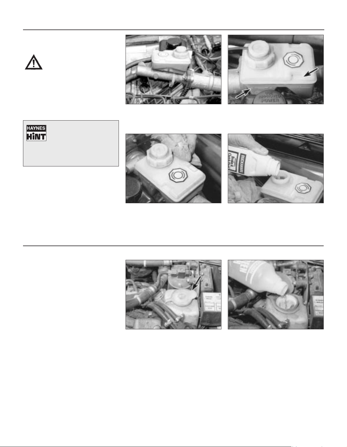
The brake fluid reservoir is located on the
right-hand rear corner of the engine
compartment, on top of the master
cylinder.
1
The upper (MAX) and lower (MIN) fluid
level markings are on the side of the brake
fluid reservoir. The fluid level must always
be kept between these two marks.
2
If topping up is necessary, first wipe
clean the area around the filler cap with a
clean cloth then unscrew the cap and
position it clear of the reservoir.
3
Carefully add fluid, avoiding spilling it on
the surrounding paintwork. Use only the
specified hydraulic fluid. After filling the
correct level, refit the cap and tighten it
securely. Wipe off any spilt fluid.
4
Screenwash additives not only keep the
winscreen clean during foul weather, they also
prevent the washer system freezing in cold
weather - which is when you are likely to need it
most. Don’t top up using plain water as the
screenwash will become too diluted, and will
freeze during cold weather. On no account use
coolant antifreeze in the washer system this could discolour or damage paintwork.
Screen washer
fluid level
If topping up is necessary, add water and
a screenwash additive in the quantities
recommended on the bottle.
2
The screen washer fluid reservoir is
located in the front, right-hand corner of
the engine compartment. The level is
visible through the reservoir body.
1
3261 Jaguar XJ6
Weekly checks 0•13
Power steering
fluid level
Before you start:
4 Park the vehicle on level ground.
4 Set the steering wheel straight-ahead.
4 The engine should be turned off.
Safety first!
l The need for frequent topping-up indicates
a leak, which should be investigated
immediately.
For the check to be
accurate, the steering must
not be turned once the
engine has been stopped.
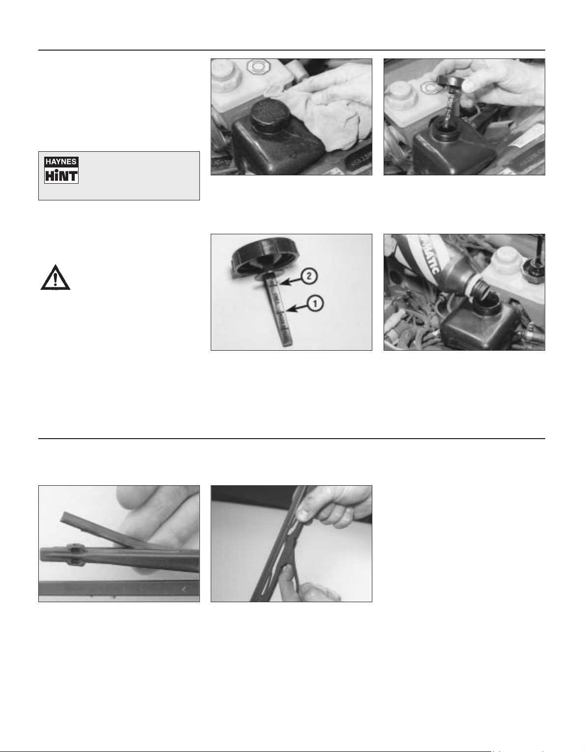
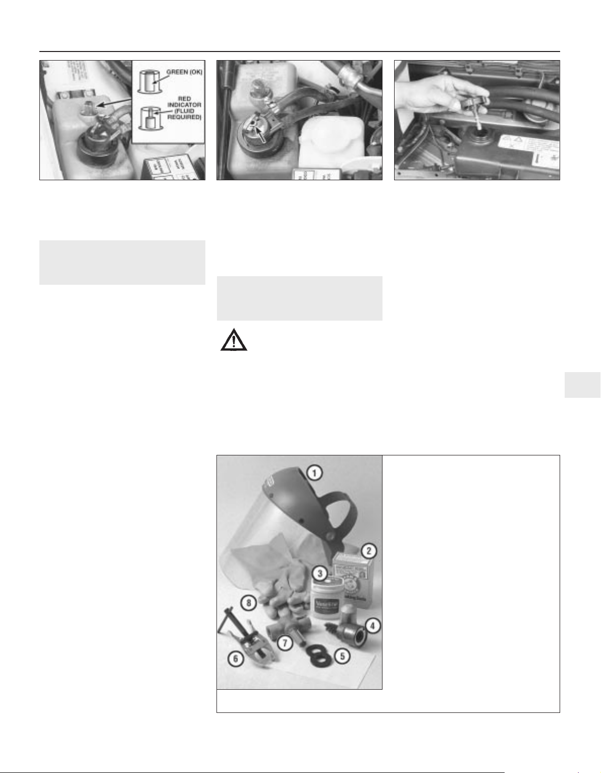
Wipe clean the area around the reservoir
cap then remove the cap noting that it
unscrews in a clockwise direction (see
arrow on cap).
1
Wipe clean the cap dipstick then insert it
fully into the reservoir and withdraw it.
2
Note the fluid level on the end of the
dipstick. If the fluid is cold (vehicle not
having been used) the fluid level should
be upto the COLD level marking (1). If the
vehicle has been driven and the fluid is hot
then the fluid level should be upto the upper
(HOT) level marking (2).
3
If necessary, top-up the reservoir with the
specified type of fluid (note that the type
of fluid differs according to model - see
“Lubricants, fluids and tyre pressures” on
page 0•16). Once the level is correct, securely
refit the reservoir cap. Do not overfill the
reservoir.
4
Wiper blades
Check the condition of the wiper blades:
if they are cracked or show signs of
deterioration, or if the glass swept area is
smeared, renew them. For maximum clarity of
vision, wiper blades should be renewed
annually.
1
To remove a wiper blade, pull the arm
fully away from the screen until it locks.
Swivel the blade then depress the locking
clip at the base of the mounting block and
slide the blade off the arm.
2
Warning:
l This check applies only to
vehicles fitted with a separate
power steering system. For
vehicles fitted with power
steering where the fluid
reservoir is part of the power hydraulic
system, this weekly check is not
applicable.
l It is essential to use the correct power
steering fluid, this being dependent on the
year of manufacture and type of system
fitted. A label attached to the fluid
reservoir will indicate the specification of
fluid. However, if necessary refer to the
driver’s handbook supplied with the
vehicle or to your local Jaguar dealer.
3261 Jaguar XJ6
0•14 Weekly checks
Tyre condition and pressure
It is very important that tyres are in good
condition, and at the correct pressure - having
a tyre failure at any speed is highly dangerous.
Tyre wear is influenced by driving style - harsh
braking and acceleration, or fast cornering,
will all produce more rapid tyre wear. As a
general rule, the front tyres wear out faster
than the rears. Interchanging the tyres from
front to rear ("rotating" the tyres) may result in
more even wear. However, if this is
completely effective, you may have the
expense of replacing all four tyres at once!
Remove any nails or stones embedded in the
tread before they penetrate the tyre to cause
deflation. If removal of a nail does reveal that
the tyre has been punctured, refit the nail so
that its point of penetration is marked. Then
immediately change the wheel, and have the
tyre repaired by a tyre dealer.
Regularly check the tyres for damage in the
form of cuts or bulges, especially in the
sidewalls. Periodically remove the wheels,
and clean any dirt or mud from the inside and
outside surfaces. Examine the wheel rims for
signs of rusting, corrosion or other damage.
Light alloy wheels are easily damaged by
"kerbing" whilst parking; steel wheels may
also become dented or buckled. A new wheel
is very often the only way to overcome severe
damage.
New tyres should be balanced when they are
fitted, but it may become necessary to rebalance them as they wear, or if the balance
weights fitted to the wheel rim should fall off.
Unbalanced tyres will wear more quickly, as
will the steering and suspension components.
Wheel imbalance is normally signified by
vibration, particularly at a certain speed
(typically around 50 mph). If this vibration is
felt only through the steering, then it is likely
that just the front wheels need balancing. If,
however, the vibration is felt through the
whole car, the rear wheels could be out of
balance. Wheel balancing should be carried
out by a tyre dealer or garage.
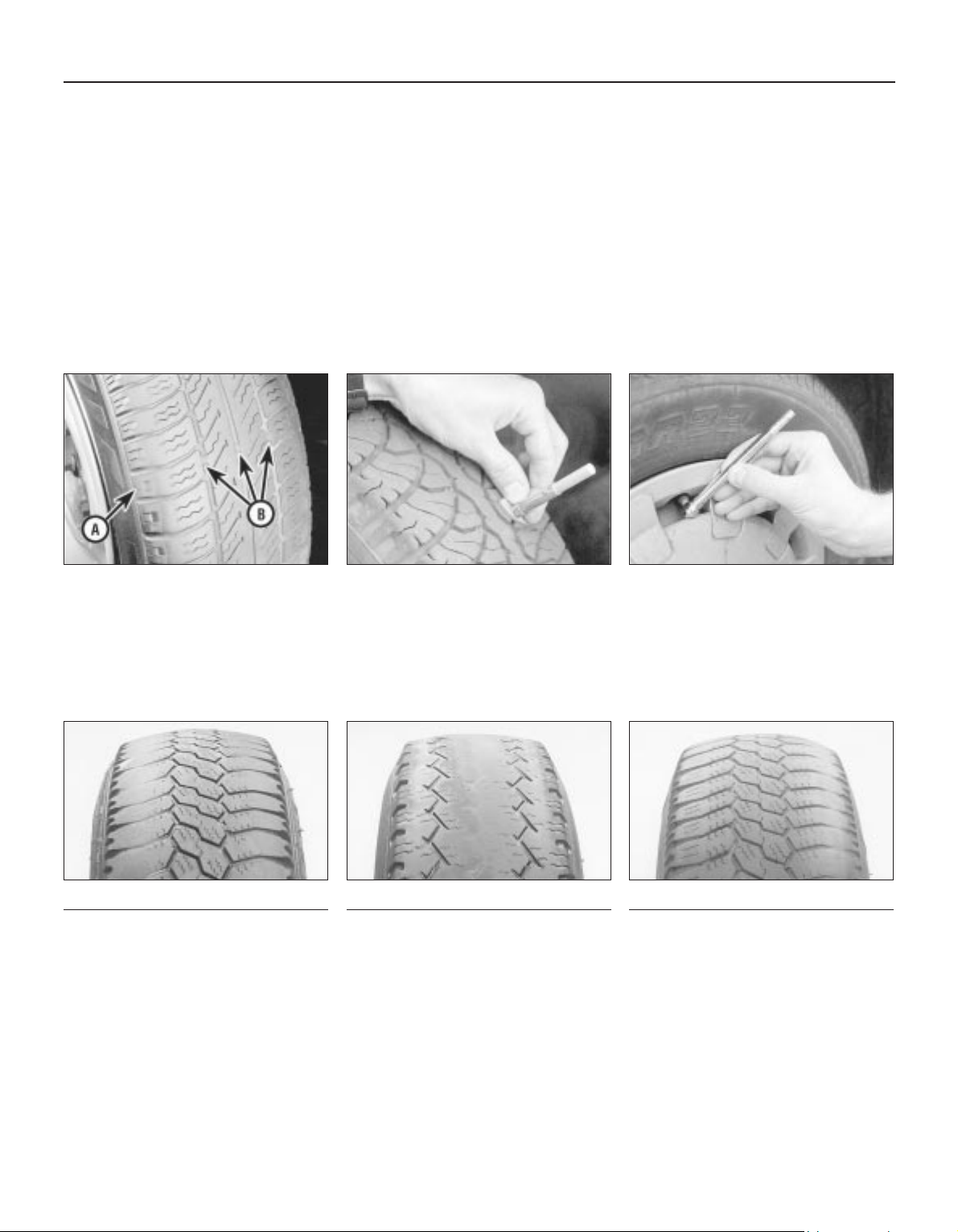
Tread Depth - visual check
The original tyres have tread wear safety
bands (B), which will appear when the tread
depth reaches approximately 1.6 mm. The
band positions are indicated by a triangular
mark on the tyre sidewall (A).
1
Tread Depth - manual check
Alternatively, tread wear can be
monitored with a simple, inexpensive device
known as a tread depth indicator gauge.
2
Tyre Pressure Check
Check the tyre pressures regularly with
the tyres cold. Do not adjust the tyre
pressures immediately after the vehicle has
been used, or an inaccurate setting will result.
3
Tyre tread wear patterns
Shoulder Wear
Underinflation (wear on both sides)
Under-inflation will cause overheating of the
tyre, because the tyre will flex too much, and
the tread will not sit correctly on the road
surface. This will cause a loss of grip and
excessive wear, not to mention the danger of
sudden tyre failure due to heat build-up.
Check and adjust pressures
Incorrect wheel camber (wear on one side)
Repair or renew suspension parts
Hard cornering
Reduce speed!
Centre Wear
Overinflation
Over-inflation will cause rapid wear of the
centre part of the tyre tread, coupled with
reduced grip, harsher ride, and the danger of
shock damage occurring in the tyre casing.
Check and adjust pressures
If you sometimes have to inflate your car’s
tyres to the higher pressures specified for
maximum load or sustained high speed, don’t
forget to reduce the pressures to normal
afterwards.
Uneven Wear
Front tyres may wear unevenly as a result of
wheel misalignment. Most tyre dealers and
garages can check and adjust the wheel
alignment (or "tracking") for a modest charge.
Incorrect camber or castor
Repair or renew suspension parts
Malfunctioning suspension
Repair or renew suspension parts
Unbalanced wheel
Balance tyres
Incorrect toe setting
Adjust front wheel alignment
Note: The feathered edge of the tread which
typifies toe wear is best checked by feel.
3261 Jaguar XJ6
Weekly checks 0•15
Battery
Caution: Before carrying out any work on the
vehicle battery, read the precautions given in
"Safety first" at the start of this manual.
4 Make sure that the battery tray is in good
condition, and that the clamp is tight.
Corrosion on the tray, retaining clamp and the
battery itself can be removed with a solution
of water and baking soda. Thoroughly rinse all
cleaned areas with water. Any metal parts
damaged by corrosion should be covered
with a zinc-based primer, then painted.
4 Periodically (approximately every three
months), check the charge condition of the
battery as described in Chapter 5.
4 If the battery is flat, and you need to jump
start your vehicle, see Roadside Repairs.
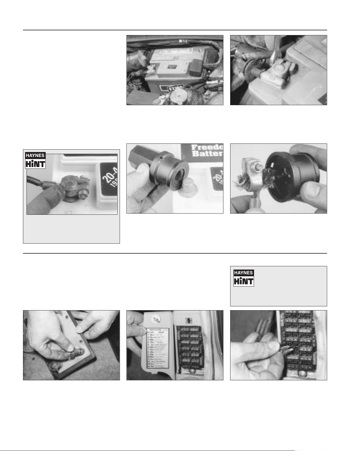
The battery is located in the left-hand,
rear corner of the engine compartment.
Check the battery terminals for signs of
corrosion and examine the battery leads
closely for signs of damage.
1
Check the battery lead clamps for
tightness to ensure good electrical
connections.
2
Battery corrosion can be kept to a
minimum by applying a layer of
petroleum jelly to the clamps and
terminals after they are reconnected.
If corrosion (white, fluffy deposits) is
evident, remove the cables from the
battery terminals, clean them with a small
wire brush, then refit them. Automotive stores
sell a tool for cleaning the battery post . . .
3
. . . as well as the battery cable clamps
4
Bulbs and fuses
4 Check all external lights and the horn. Refer
to the appropriate Sections of Chapter 12 for
details if any of the circuits are found to be
inoperative.
4 Visually check all accessible wiring
connectors, harnesses and retaining clips for
security, and for signs of chafing or damage.
If you need to check your
brake lights and indicators
unaided, back up to a wall or
garage door and operate the
lights. The reflected light should show if
they are working properly.
If a single indicator light, stop light or
headlight has failed, it is likely that a bulb
has blown and will need to be replaced.
Refer to Chapter 12 for details. If both stop
lights have failed, it is possible that the switch
has failed (see Chapter 9).
If more than one indicator light or tail light
has failed it is likely that either a fuse has
blown or that there is a fault in the circuit.
The fuseboxes are located behind the left and
right side kick panels and in the centre
console glove box (see Chapter 12).
2
To replace a blown fuse, simply pull it out
and fit a new fuse of the correct rating
(see Chapter 12). If the fuse blows again,
it is important that you find out why - a
complete checking procedure is given in
Chapter 12.
3
1
0•16 Lubricants, fluids and tyre pressures
3261 Jaguar XJ6
Lubricants and fluids
Engine . . . . . . . . . . . . . . . . . . . . . . . . . . Multigrade engine oil to API SG or higher (Duckhams QS, QXR, Hypergrade Plus,
Hypergrade, or 10W-40 Motor Oil)
Cooling system . . . . . . . . . . . . . . . . . . . Ethylene glycol based (phosphate free) antifreeze
(Duckhams Antifreeze and Summer Coolant)
Automatic transmission . . . . . . . . . . . . Dexron type II automatic transmission fluid (ATF) (Duckhams Uni-Matic)
Differential:
Standard differential . . . . . . . . . . . . . . SAE EP90 to API GL5 (Duckhams 80W-90S Gear Oil)
Powr-lok differential . . . . . . . . . . . . . . . SAE 90 to API GL5 (Duckhams Hypoid 90 DL)
Braking system . . . . . . . . . . . . . . . . . . . Hydraulic fluid to DOT 4 (Duckhams Universal Brake and Clutch Fluid)
Power steering (with separate reservoir) . dependent on year of manufacture and system fitted - refer to your Jaguar dealer
Power hydraulic system . . . . . . . . . . . . . Castrol or Jaguar hydraulic system mineral oil (HSMO) Refer to your Jaguar dealer
Tyre pressures
Note: Tyre pressures must always be checked with the tyres cold to ensure accuracy.
Front . . . . . . . . . . . . . . . . . . . . . . . . . . . . . . . . . . . . . . . . . . . 34 psi (2.3 bar)
Rear . . . . . . . . . . . . . . . . . . . . . . . . . . . . . . . . . . . . . . . . . . . 34 psi (2.3 bar)
Note: Jaguar state that the tyre pressures maybe reduced by up to 8 psi (0.6 bar) on the front tyres and 6 psi (0.4 bar) on the rear
tyres to increase the ride comfort. This is only allowable if the vehicle is not to be driven at speeds in excess of 100 mph (160 kmh);
if speeds are to exceed this, the tyres must be run at the specified pressures.
Oils perform vital tasks in all engines. The
higher the engine’s performance, the greater
the demand on lubricants to minimise wear as
well as optimise power and economy.
Duckhams tailors lubricants to the highest
technical standards, meeting and exceeding
the demands of all modern engines.
HOW ENGINE OIL WORKS
• Beating friction
Without oil, the surfaces inside your engine
which rub together will heat, fuse and quickly
cause engine seizure. Oil, and its special
additives, forms a molecular barrier between
moving parts, to stop wear and minimise heat
build-up.
• Cooling hot spots
Oil cools parts that the engine’s water-based
coolant cannot reach, bathing the combustion
chamber and pistons, where temperatures
may exceed 1000°C. The oil assists in
transferring the heat to the engine cooling
system. Heat in the oil is also lost by air flow
over the sump, and via any auxiliary oil cooler.
• Cleaning the inner engine
Oil washes away combustion by-products
(mainly carbon) on pistons and cylinders,
transporting them to the oil filter, and holding
the smallest particles in suspension until they
are flushed out by an oil change. Duckhams
oils undergo extensive tests in the laboratory,
and on the road.
Engine oil types
Mineral oils are the “traditional” oils,
generally suited to older engines and cars not
used in harsh conditions. Duckhams
Hypergrade Plus and Hypergrade are well
suited for use in most popular family cars.
Diesel oils such as Duckhams Diesel are
specially formulated for Diesel engines,
including turbocharged models and 4x4s.
Synthetic oils are the state-of-the-art in
lubricants, offering ultimate protection, but at
a fairly high price. One such is Duckhams QS,
for use in ultra-high performance engines.
Semi-synthetic oils offer high performance
engine protection, but at less cost than full
synthetic oils. Duckhams QXR is an ideal choice
for hot hatches and hard-driven cars.
For help with technical
queries on lubricants,
call Duckhams Oils
on 0181 290 8207
Choosing your engine oil
Note: It is
antisocial and
illegal to dump oil
down the drain.
To find the
location of your
local oil recycling
bank, call this
number free.
3261 Jaguar XJ6
1
Chapter 1
Routine maintenance and servicing
Air cleaner element renewal . . . . . . . . . . . . . . . . . . . . . . . . . . . . . . . . 17
Automatic transmission fluid and filter renewal . . . . . . . . . . . . . . . . . 26
Automatic transmission fluid level check . . . . . . . . . . . . . . . . . . . . . 8
Battery check and general information . . . . . . . . . . . . . . . . . . . . . . . 6
Brake fluid renewal . . . . . . . . . . . . . . . . . . . . . . . . . . . . . . . . . . . . . . 28
Braking system - general check and adjustment . . . . . . . . . . . . . . . 11
Coolant renewal . . . . . . . . . . . . . . . . . . . . . . . . . . . . . . . . . . . . . . . . . 30
Crankcase ventilation system check . . . . . . . . . . . . . . . . . . . . . . . . . 20
Differential oil level check . . . . . . . . . . . . . . . . . . . . . . . . . . . . . . . . . 9
Differential oil renewal . . . . . . . . . . . . . . . . . . . . . . . . . . . . . . . . . . . . 27
Drivebelt check and renewal . . . . . . . . . . . . . . . . . . . . . . . . . . . . . . . 21
Engine oil and filter renewal . . . . . . . . . . . . . . . . . . . . . . . . . . . . . . . . 3
Exhaust system check . . . . . . . . . . . . . . . . . . . . . . . . . . . . . . . . . . . . 10
Front wheel alignment check . . . . . . . . . . . . . . . . . . . . . . . . . . . . . . . 24
Front wheel bearing check and adjustment . . . . . . . . . . . . . . . . . . . 22
Fuel filter renewal . . . . . . . . . . . . . . . . . . . . . . . . . . . . . . . . . . . . . . . . 18
General information . . . . . . . . . . . . . . . . . . . . . . . . . . . . . . . . . . . . . . 1
General lubrication . . . . . . . . . . . . . . . . . . . . . . . . . . . . . . . . . . . . . . . 14
Handbrake shoes check . . . . . . . . . . . . . . . . . . . . . . . . . . . . . . . . . . 29
Headlight beam check . . . . . . . . . . . . . . . . . . . . . . . . . . . . . . . . . . . . 25
Hose and fluid leak check . . . . . . . . . . . . . . . . . . . . . . . . . . . . . . . . . 7
Ignition system check . . . . . . . . . . . . . . . . . . . . . . . . . . . . . . . . . . . . 19
Intensive maintenance . . . . . . . . . . . . . . . . . . . . . . . . . . . . . . . . . . . . 2
Power hydraulic system fluid level check . . . . . . . . . . . . . . . . . . . . . 5
Propshaft check . . . . . . . . . . . . . . . . . . . . . . . . . . . . . . . . . . . . . . . . . 23
Road test . . . . . . . . . . . . . . . . . . . . . . . . . . . . . . . . . . . . . . . . . . . . . . 15
Seat belt check . . . . . . . . . . . . . . . . . . . . . . . . . . . . . . . . . . . . . . . . . 13
Spark plug check . . . . . . . . . . . . . . . . . . . . . . . . . . . . . . . . . . . . . . . . 4
Spark plug renewal . . . . . . . . . . . . . . . . . . . . . . . . . . . . . . . . . . . . . . 16
Steering and suspension check . . . . . . . . . . . . . . . . . . . . . . . . . . . . 12
1•1
Contents
Easy, suitable for
novice with little
experience
Fairly easy, suitable
for beginner with
some experience
Fairly difficult,
suitable for competent
DIY mechanic
Difficult, suitable for
experienced DIY
mechanic
Very difficult,
suitable for expert DIY
or professional
Degrees of difficulty
5
4
3
2
1
Lubricants and fluids
Refer to “Weekly checks”
Capacities
Engine oil
Including oil filter . . . . . . . . . . . . . . . . . . . . . . . . . . . . . . . . . . . . . . . . . . . 8.0 litres
Cooling system
All models (approximate):
From dry . . . . . . . . . . . . . . . . . . . . . . . . . . . . . . . . . . . . . . . . . . . . . . . 12.8 litres
Drain and refill . . . . . . . . . . . . . . . . . . . . . . . . . . . . . . . . . . . . . . . . . . . 9.2 litres
Transmission
Automatic transmission (approximate):
From dry:
3.2 litre model . . . . . . . . . . . . . . . . . . . . . . . . . . . . . . . . . . . . . . . . . 7.4 litres
3.6 and 4.0 litre models . . . . . . . . . . . . . . . . . . . . . . . . . . . . . . . . . 8.0 litres
Drain and refill . . . . . . . . . . . . . . . . . . . . . . . . . . . . . . . . . . . . . . . . . . . 3.0 litres
Differential
All models (approximate) . . . . . . . . . . . . . . . . . . . . . . . . . . . . . . . . . . . . 2.1 litres
Cooling system
Antifreeze mixture:
50% antifreeze . . . . . . . . . . . . . . . . . . . . . . . . . . . . . . . . . . . . . . . . . . Protection down to -37°C (5°F)
55% antifreeze . . . . . . . . . . . . . . . . . . . . . . . . . . . . . . . . . . . . . . . . . . Protection down to -45°C (-22°F)
Note: Refer to antifreeze manufacturer for latest recommendations.
Ignition system
Spark plugs:
Type:
3.2 litre model . . . . . . . . . . . . . . . . . . . . . . . . . . . . . . . . . . . . . . . . . RC12YCC
3.6 and 4.0 litre models . . . . . . . . . . . . . . . . . . . . . . . . . . . . . . . . . RC9YCC
Electrode gap . . . . . . . . . . . . . . . . . . . . . . . . . . . . . . . . . . . . . . . . . . . 0.9 mm
*The spark plug gap quoted is that recommended by Champion
for their specified plug listed above. If spark plugs of any other type
are to be fitted, refer to their manufacturer’s recommendations.
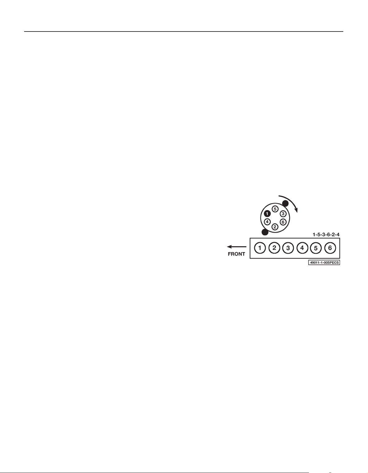
Engine firing order . . . . . . . . . . . . . . . . . . . . . . . . . . . . . . . . . . . . . . . . . 1-5-3-6-2-4
Distributor rotation . . . . . . . . . . . . . . . . . . . . . . . . . . . . . . . . . . . . . . . . . Clockwise
Ignition timing . . . . . . . . . . . . . . . . . . . . . . . . . . . . . . . . . . . . . . . . . . . . . See Chapter 5
Brakes
Disc brake pad friction material minimum thickness:
Front . . . . . . . . . . . . . . . . . . . . . . . . . . . . . . . . . . . . . . . . . . . . . . . . . 4.0 mm
Rear . . . . . . . . . . . . . . . . . . . . . . . . . . . . . . . . . . . . . . . . . . . . . . . . . 3.0 mm
Handbrake shoe friction material minimum thickness . . . . . . . . . . . . . . 1.5 mm
Handbrake adjustment . . . . . . . . . . . . . . . . . . . . . . . . . . . . . . . . . . . . . . 3 to 5 clicks
Torque wrench settings Nm lbf ft
Automatic transmission sump pan bolts . . . . . . . . . . . . . . . . . . . . . . . . 8 6
Automatic transmission dipstick tube nut . . . . . . . . . . . . . . . . . . . . . . . 20 15
Spark plugs . . . . . . . . . . . . . . . . . . . . . . . . . . . . . . . . . . . . . . . . . . . . . . . 23 to 28 17 to 21
Wheel nuts . . . . . . . . . . . . . . . . . . . . . . . . . . . . . . . . . . . . . . . . . . . . . . . 102 75
1•2 Servicing specifications
3261 Jaguar XJ6
Cylinder location and distributor rotation

The maintenance intervals in this manual are provided with the
assumption that you, not the dealer, will be carrying out the work.
These are the minimum maintenance intervals recommended by us for
vehicles driven daily. If you wish to keep your vehicle in peak condition
at all times, you may wish to perform some of these procedures more
often. We encourage frequent maintenance, because it enhances the
efficiency, performance and resale value of your vehicle.
When the vehicle is new, it should be serviced by a factoryauthorised dealer service department, in order to preserve the factory
warranty.
Maintenance schedule 1•3
1
3261 Jaguar XJ6
Weekly, or every 250 miles (400 km)
mm Carry out all the operations given in “Weekly
checks” at the start of this manual.
mm Renew the fuel filter (Section 18)
mm Check the ignition system components (Section 19)
mm Check the crankcase ventilation system
(Section 20)
mm Check the condition and tension of the drivebelt(s)
(Section 21)
mm Check the front wheel bearing adjustment and
repack with grease (Section 22)
mm Check the propshaft fasteners are tightened to the
specified torque (Section 23)
mm Check the front wheel alignment (Section 24)
mm Check the headlight beam alignment (Section 25)
Every 7500 miles (12 000 km)
or 6 months, whichever comes first
In addition to the operations listed previously, carry out the following:
mm Renew the engine oil and filter (Section 3)
mm Check the spark plugs (Section 4)
mm Check the power hydraulics fluid level (Section 5)
mm Check the battery (Section 6)
mm Check all pipes and hoses for signs of damage or
leakage (Section 7)
mm Check the automatic transmission fluid level
(Section 8)
mm Check the differential oil level (Section 9)
mm Check the condition of the exhaust system
(Section 10)
mm Check the brake pads and discs for wear and
adjust the handbrake (Section 11)
mm Check the steering and suspension components
for wear or damage and check the wheel nuts are
tightened to the correct torque (Section 12)
mm Check the condition of the seat belts (Section 13)
mm Lubricate all locks and hinges, and exposed cables
(Section 14)
mm Carry out a road test (Section 15)
Every 2 years, regardless of mileage
mm Renew the coolant (Section 30)
Every 60 000 miles (96 000 km)
In addition to the operations listed previously, carry out the following:
mm Check the handbrake shoes for wear (Section 29)
Every 30 000 miles (48 000 km)
or 2 years, whichever comes first
In addition to the operations listed previously, carry out the following:
mm Renew the automatic transmission fluid and filter
(Section 26)
mm Renew the differential oil (Section 27)
mm Renew the brake fluid (Section 28)
Every 15 000 miles (24 000 km)
or 12 months, whichever comes first
In addition to the operations listed previously, carry out the following:
mm Renew the spark plugs (Section 16)
mm Renew the air cleaner element (Section 17)
1•4 Maintenance - component location
3261 Jaguar XJ6
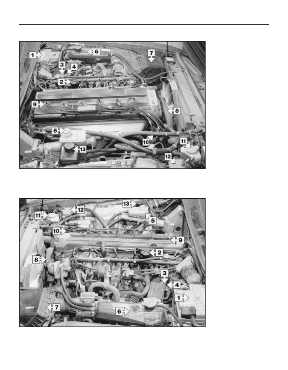
1 Battery
2 Oil filler cap
3 Engine oil dipstick (not visible)
4 Automatic transmission
dipstick (not visible)
5 Brake fluid reservoir
6 Coolant reservoir
(expansion tank)
7 Air cleaner housing
8 Upper radiator hose
9 Spark plugs
10 Distributor
11 Windscreen washer fluid
reservoir
12 Power hydraulic system fluid
reservoir
13 Power steering fluid reservoir
Underbonnet view from the left-hand side of the vehicle
Underbonnet view from the right-hand side of the vehicle
1 Battery
2 Oil filler cap
3 Engine oil dipstick (not visible)
4 Automatic transmission
dipstick (not visible)
5 Brake fluid reservoir
6 Coolant reservoir (expansion
tank)
7 Air cleaner housing
8 Upper radiator hose
9 Spark plugs
10 Distributor
11 Windscreen washer fluid
reservoir
12 Power hydraulic system fluid
reservoir
13 Power steering fluid reservoir
Maintenance - component location 1•5
1
3261 Jaguar XJ6
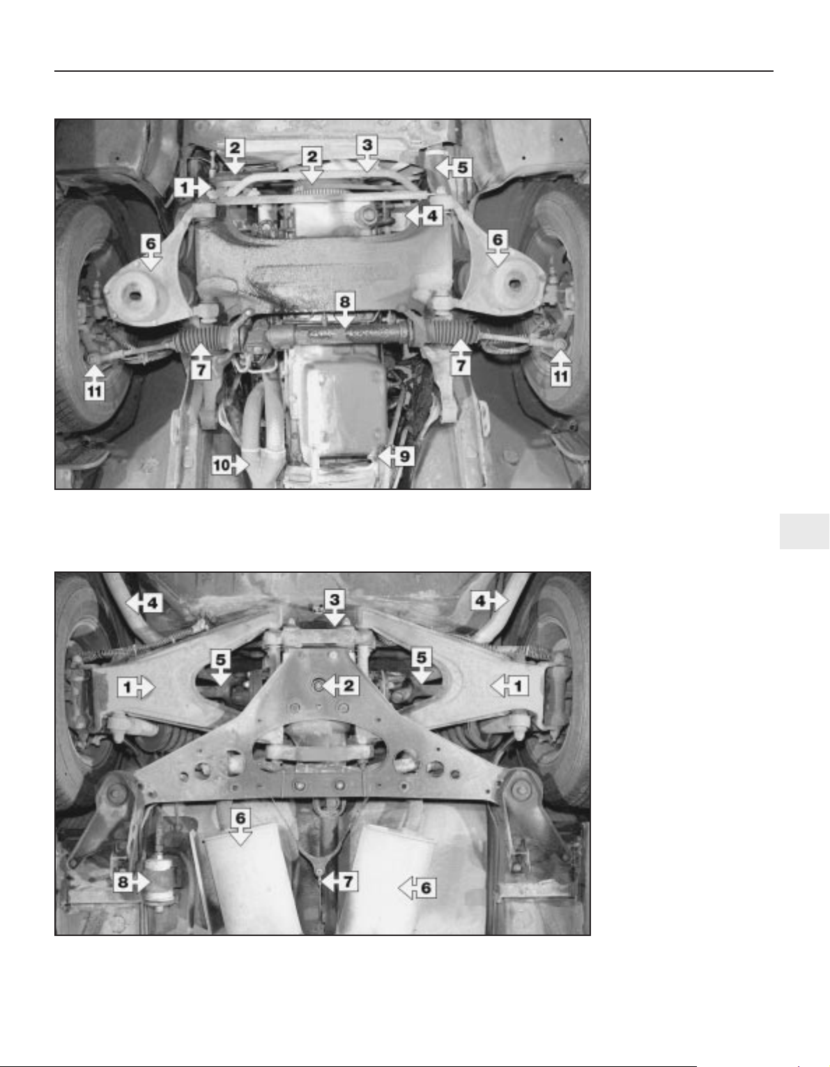
Front underbody view
1 Air conditioning compressor
2 Drivebelts
3 Anti-roll bar
4 Alternator
5 Lower radiator hose
6 Lower control arm
7 Steering gear boot
8 Steering gear
9 Engine sump drain plug
10 Exhaust system
11 Outer tie-rod end
Rear underbody view (typical)
1 Rear suspension control arms
2 Differential drain plug
3 Differential filler plug
(not visible)
4 Exhaust pipe
5 Driveshaft
6 Silencers
7 Handbrake cable
8 Fuel filter
1 General information
1 This Chapter is designed to help the home
mechanic maintain his/her vehicle for safety,
economy, long life and peak performance.
2 The Chapter contains a master
maintenance schedule, followed by Sections
dealing specifically with each task in the
schedule. Visual checks, adjustments,
component renewal and other helpful items
are included. Refer to the accompanying
illustrations of the engine compartment and
the underside of the vehicle for the locations
of the various components.
3 Servicing your vehicle in accordance with
the mileage/time maintenance schedule and
the following Sections will provide a planned
maintenance programme, which should result
in a long and reliable service life. This is a
comprehensive plan, so maintaining some
items but not others at the specified service
intervals, will not produce the same results.
4 As you service your vehicle, you will
discover that many of the procedures can and should - be grouped together, because of
the particular procedure being performed, or
because of the proximity of two otherwiseunrelated components to one another. For
example, if the vehicle is raised for any
reason, the exhaust can be inspected at the
same time as the suspension and steering
components.
5 The first step in this maintenance
programme is to prepare yourself before the
actual work begins. Read through all the
Sections relevant to the work to be carried out,
then make a list and gather all the parts and
tools required. If a problem is encountered,
seek advice from a parts specialist, or a dealer
service department.
2 Intensive maintenance
1 If, from the time the vehicle is new, the
routine maintenance schedule is followed
closely, and frequent checks are made of fluid
levels and high-wear items, as suggested
throughout this manual, the engine will be
kept in relatively good running condition, and
the need for additional work will be minimised.
2 It is possible that there will be times when
the engine is running poorly due to the lack of
regular maintenance. This is even more likely
if a used vehicle, which has not received
regular and frequent maintenance checks, is
purchased. In such cases, additional work
may need to be carried out, outside of the
regular maintenance intervals.
3 If engine wear is suspected, a compression
test (refer to Chapter 2) will provide valuable
information regarding the overall performance
of the main internal components. Such a test
can be used as a basis to decide on the extent
of the work to be carried out. If, for example, a
compression test indicates serious internal
engine wear, conventional maintenance as
described in this Chapter will not greatly
improve the performance of the engine, and
may prove a waste of time and money, unless
extensive overhaul work is carried out first.
4 The following series of operations are those
which are most often required to improve the
performance of a generally poor-running
engine:
Primary operations
a) Clean, inspect and test the battery
(Section 6).
b) Check all the engine-related fluids (refer
to “Weekly checks”).
c) Check the condition and tension of the
auxiliary drivebelt (Section 21).
d) Renew the spark plugs (Section 16).
e) Inspect the distributor cap and rotor arm
(Section 19).
f) Check the condition of the air filter, and
renew if necessary (Section 17).
g) Renew the fuel filter (Section 18).
h) Check the condition of all hoses, and
check for fluid leaks (Section 7).
i) Check the exhaust gas emissions (see
Chapter 6).
5 If the above operations do not prove fully
effective, carry out the following secondary
operations:
Secondary operations
All items listed under “Primary operations”,
plus the following:
a) Check the charging system (refer to
Chapter 5).
b) Check the ignition system (refer to
Chapter 5).
c) Check the fuel system (refer to Chapter 4).
d) Renew the distributor cap and rotor arm
(Section 19).
e) Renew the ignition HT leads (Section 19).
1•6 Maintenance procedures
3261 Jaguar XJ6
Every 7500 miles (12 000 km) or 6 months
3 Engine oil and filter renewal
2
1 Frequent oil changes are the best
preventive maintenance the home mechanic
can give the engine, because ageing oil
becomes diluted and contaminated, which
leads to premature engine wear.
2 Make sure that you have all the necessary
tools before you begin this procedure (see
illustration). You should also have plenty of
rags or newspapers handy for mopping up
any spills.
3 Access to the underside of the vehicle is
greatly improved if the vehicle can be lifted on
a hoist, driven onto ramps or supported by
axle stands.
4 If this is your first oil change, get under the
vehicle and familiarise yourself with the
location of the oil drain plug. The engine and
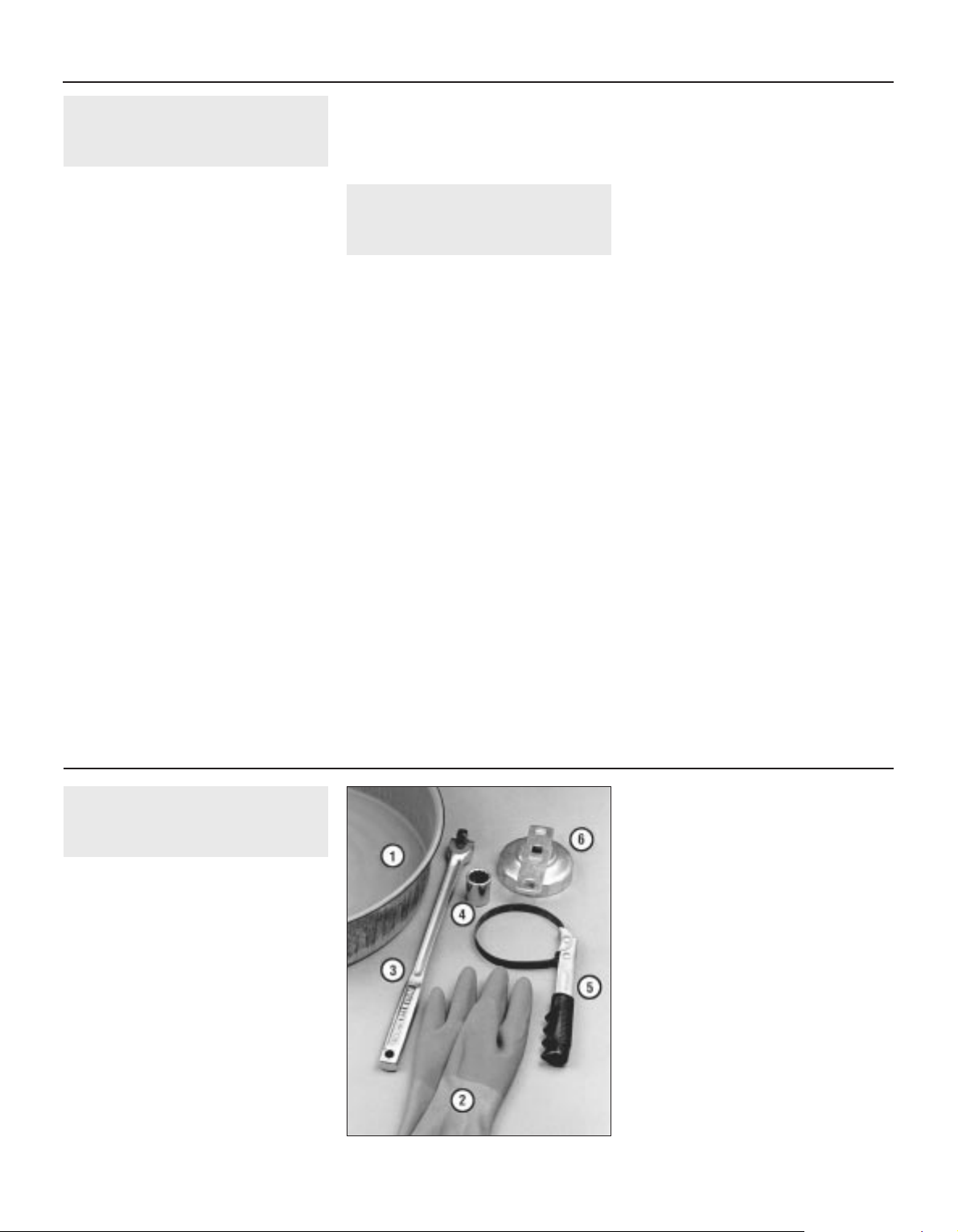
3.2 These tools are required when
changing the engine oil and filter
1 Drain pan - It should be fairly shallow in
depth, but wide in order to prevent spills
2 Rubber gloves - When removing the drain
plug and filter, it is inevitable that you will
get oil on your hands (the gloves will
prevent burns)
3 Breaker bar - Sometimes the oil drain plug
is pretty tight and a long breaker bar is
needed to loosen it
4 Socket – To be used with the breaker bar
or a ratchet (must be the correct size to fit
the drain plug)
5 Filter wrench - This is a metal band-type
wrench, which requires clearance around
the filter to be effective
6 Filter wrench - This type fits on the bottom
of the filter and can be turned with a
ratchet or breaker bar (different size
spanners are available for different types of
filters)

exhaust components will be warm during the
actual work, so try to anticipate any potential
problems before the engine and accessories
are hot.
5 Park the vehicle on a level spot. Start the
engine and allow it to reach its normal
operating temperature (the needle on the
temperature gauge should be at least above
the bottom mark). Warm oil and contaminates
will flow out more easily. Turn off the engine
when it’s warmed up. Remove the oil filler cap
located next to the valve cover.
6 Raise the vehicle and support it on axle
stands.
Warning: To avoid personal
injury, never get beneath the
vehicle when it is supported by
only by a jack. The jack provided
with your vehicle is designed solely for
raising the vehicle to remove and replace
the wheels. Always use axle stands to
support the vehicle when it becomes
necessary to place your body underneath
the vehicle.
7 Being careful not to touch the hot exhaust
components, place the drain pan under the
drain plug in the bottom of the pan and
remove the plug (see illustration). You may
want to wear gloves while unscrewing the
plug the final few turns if the engine is really
hot.
8 Allow the old oil to drain into the pan. It may
be necessary to move the pan farther under
the engine as the oil flow slows to a trickle.
Inspect the old oil for the presence of metal
shavings and chips.
9 After all the oil has drained, wipe off the
drain plug with a clean rag. Even minute metal
particles clinging to the plug would
immediately contaminate the new oil.
10 Clean the area around the drain plug
opening, refit the plug and tighten it securely,
but do not strip the threads.
11 Move the drain pan into position under the
oil filter.
12 Remove all tools, rags, etc. from under
the vehicle, being careful not to spill the oil in
the drain pan, then lower the vehicle.
13 Loosen the oil filter (see illustration) by
turning it anti-clockwise with the filter wrench.
Any standard filter wrench should work. Once
the filter is loose, use your hands to unscrew
it from the block. Just as the filter comes
away from the block, immediately tilt the open
end up to prevent the oil inside the filter from
spilling out.
Warning: The engine exhaust
pipes may still be hot, so be
careful.
14 With a clean rag, wipe off the mounting
surface on the block. If a residue of old oil is
allowed to remain, it will smoke when the
block is heated up. It will also prevent the new
filter from seating properly. Also make sure
that the none of the old gasket remains stuck
to the mounting surface. It can be removed
with a scraper if necessary.
15 Compare the old filter with the new one to
make sure they are the same type. Smear
some engine oil on the rubber gasket of the
new filter and screw it into place (see
illustration). Because over-tightening the
filter will damage the gasket, do not use
a filter wrench to tighten the filter. Tighten it by
hand until the gasket contacts the seating
surface. Then seat the filter by giving it an
additional 3/4-turn.
16 Add new oil to the engine through the oil
filler cap next to the valve cover. Use a spout
or funnel to prevent oil from spilling onto the
top of the engine. Pour three litres of fresh oil
into the engine. Wait a few minutes to allow
the oil to drain into the pan, then check the
level on the oil dipstick (see “Weekly checks”).
If the oil level is at or near the H mark, refit the
filler cap hand tight, start the engine and allow
the new oil to circulate.
17 Allow the engine to run for about a minute.
While the engine is running, look under the
vehicle and check for leaks at the sump drain
plug and around the oil filter. If either is
leaking, stop the engine and tighten the plug
or filter slightly.
18 Wait a few minutes to allow the oil to
trickle down into the pan, then recheck the
level on the dipstick and, if necessary, add
enough oil to bring the level to the H mark.
19 During the first few trips after an oil
change, make it a point to check frequently
for leaks and proper oil level.
20 The old oil drained from the engine cannot
be reused in its present state and should be
disposed of. Check with your local authority,
or with a local garage to see whether they will
accept the oil for recycling. Don’t pour used
oil into drains or onto the ground. After the oil
has cooled, it can be drained into a suitable
container (capped plastic jugs, topped
bottles, etc.) for transport to an approved
disposal site.
4 Spark plug check
2
1 Spark plug renewal requires a spark plug
socket which fits onto a ratchet spanner. This
socket is lined with a rubber grommet to
protect the porcelain insulator of the spark
plug and to hold the plug while you insert it
into the spark plug hole. You will also need a
wire-type feeler gauge to check and adjust
the spark plug gap and a torque wrench to
tighten the new plugs to the specified torque
(see illustration).
2 If you are replacing the plugs, purchase the
new plugs, adjust them to the proper gap and
then replace each plug one at a time. Note:
When buying new spark plugs, it’s essential
that you obtain the correct plugs for your
specific vehicle. This information can be found
in the Specifications Section at the beginning
of this Chapter, on the Vehicle Emissions
Control Information (VECI) label located on the
underside of the bonnet (where fitted)or in the
owner’s manual. If these sources specify
different plugs, purchase the spark plug type
specified on the VECI label because that
information is provided specifically for your
engine.
Every 7500 miles or 6 months 1•7
1
3.7 The oil drain plug (arrowed) is located
at the rear of the sump - use a ring
spanner or socket to remove it
3.13 The oil filter is located on the left side
of the engine - use a filter wrench for
removal (tighten the new filter by hand)
3.15 Lubricate the oil filter gasket with
clean engine oil before refitting the filter
3261 Jaguar XJ6
Note: It is
antisocial and
illegal to dump oil
down the drain.
To find the
location of your
local oil recycling
bank, call this
number free.

3 Inspect each of the new plugs for defects. If
there are any signs of cracks in the porcelain
insulator of a plug, don’t use it.
4 Check the electrode gaps of the new plugs.
Check the gap by inserting the wire gauge of
the proper thickness between the electrodes
at the tip of the plug (see illustration). The
gap between the electrodes should be
identical to that listed in this Chapter’s
Specifications or on the VECI label (as
applicable). If the gap is incorrect, use the
notched adjuster on the feeler gauge body to
bend the curved side electrode slightly (see
illustration).
5 If the side electrode is not exactly over the
centre electrode, use the notched adjuster to
align them.
Caution: If the gap of a new plug must be
adjusted, bend only the base of the earth
electrode - do not touch the tip.
Removal
6 To prevent the possibility of mixing up
spark plug leads, work on one spark plug at a
time. Remove the lead and boot from one
spark plug. Grasp the boot - not the lead - as
shown, give it a half twisting motion and pull
straight up (see illustration).
7 If compressed air is available, blow any dirt
or foreign material away from the spark plug
area before proceeding (a common bicycle
pump will also work).
8 Remove the spark plug (see illustration).
9 Whether you are replacing the plugs at this
time or intend to re-use the old plugs,
compare each old spark plug with the chart
shown on the inside back cover of this manual
to determine the overall running condition of
the engine.
Refitting
10 Prior to refitting, apply a coat of anti-seize
compound to the plug threads (see
illustration). It’s often difficult to insert spark
plugs into their holes without cross-threading
them. To avoid this possibility, fit a short piece
of 3/8-inch internal diameter (ID) rubber hose
over the end of the spark plug (see Haynes
Hint). The flexible hose acts as a universal
joint to help align the plug with the plug hole.
Should the plug begin to cross-thread, the
hose will slip on the spark plug, preventing
thread damage. Tighten the plug to the torque
listed in this Chapter’s Specifications. In the
absence of a torque wrench, tighten each
plug until you feel it seat, and then by a further
quarter-turn only. Do not overtighten the
spark plugs.
11 Attach the plug lead to the new spark
plug, again using a twisting motion on the
boot until it is firmly seated on the end of the
spark plug.
12 Follow the above procedure for the
remaining spark plugs, replacing them one at
a time to prevent mixing up the spark plug
leads.
1•8 Every 7500 miles or 6 months
4.4a Spark plug manufacturers
recommend using a wire-type gauge when
checking the gap - if the wire does not
slide between the electrodes with a slight
drag, adjustment is required
4.4b To change the gap, bend the side
electrode only, as indicated by the arrows,
and be very careful not to crack or chip the
porcelain insulator surrounding the
centre electrode
4.6 When removing the spark plug leads,
grasp only the boot and use a
twisting/pulling motion
4.8 Use a spark plug socket with a long
extension to unscrew the spark plugs
3261 Jaguar XJ6
4.1 Tools required for changing
spark plugs
1 Spark plug socket - This will have special
padding inside to protect the spark plug
porcelain insulator
2 Torque wrench - Although not mandatory,
use of this tool is the best way to ensure
that the plugs are tightened properly
3 Ratchet - to fit the plug socket
4 Extension - Depending on model and
accessories, you may need special
extensions and universal joints to reach
one or more of the plugs
5 Spark plug gap gauge - This gauge for
checking the gap comes in a variety of
styles. Make sure the gap for your engine
is included
4.10 Apply a coat of anti-seize compound
to the spark plug threads
A length of 3/8-inch ID rubber hose will
save time and prevent damaged
threads when refitting the spark plugs
5 Power hydraulic system
fluid level check
1
Caution: Use only Castrol or Jaguar
hydraulic system mineral oil (HSMO) in the
power hydraulic system (available at
Jaguar dealer service departments).
1 The power hydraulic system controls the ride
levelling and the brake servo systems. The
fluid reservoir also supplies the power
steering system on some models. The level
of the fluid should be carefully maintained. Low
fluid levels can adversely affect the riding and
braking capabilities of your vehicle. The power
hydraulic system fluid reservoir is located on
the right inner wing of the engine compartment.
1988 and 1989 models
2 The fluid level can easily be checked by
viewing the reservoir sight glass. A green
indicator in the sight glass indicates an OK
condition, while a red indicator in the sight glass
requires fluid to be added (see illustration).
3 If additional fluid is required, pop open the
plastic tab located on top of the reservoir cap
(see illustration).
4 Insert the mineral oil dispensing tube into
the reservoir filler hole. Push down and turn
until the dispensing tube is locked in place.
5 Add fluid until the green indicator in the
sight glass appears, then release the
dispensing tube by pushing downward and
turning the opposite direction of refitting.
1990 to 1994 models
6 The fluid level can be checked by removing
the cap and observing the level of fluid on the
dipstick.
7 Wipe off the fluid with a clean rag, reinsert
it, then withdraw it and read the fluid level
(see illustration). The dipstick is marked so
the fluid can be checked either cold or hot.
The level should be at the HOT mark if the
fluid was hot to the touch. It should be at the
COLD mark if the fluid was cool to the touch.
At no time should the fluid level drop below
the add mark.
8 If additional fluid is required, pour the
specified type directly into the reservoir, using
a funnel to prevent spills.
6 Battery check
and general information
1
Warning: Certain precautions
must be followed when working
with the battery. Hydrogen gas,
which is highly flammable, is
always present in the battery cells, so don’t
smoke, and keep naked flames and sparks
away from the battery. The electrolyte in
the battery is actually dilute sulphuric acid,
which will cause injury if splashed on your
skin or in your eyes. It will also ruin clothes
and painted surfaces. When removing the
battery cables, always detach the negative
cable first and hook it up last!
1 A routine preventive maintenance program
for the battery in your vehicle is the only way
to ensure quick and reliable starts. But before
performing any battery maintenance, make
sure that you have the proper equipment
necessary to work safely around the battery
(see illustration).
2 There are also several precautions that
should be taken whenever battery
maintenance is performed. Before servicing
the battery, always turn the engine and all
accessories off and disconnect the cable from
the negative terminal of the battery.
3 The battery produces hydrogen gas, which
is both flammable and explosive. Never create
a spark, smoke or light a match around the
battery. Always charge the battery in a
ventilated area.
4 Electrolyte contains poisonous and corrosive
sulphuric acid. Do not allow it to get in your
eyes, on your skin or on your clothes, and
Every 7500 miles or 6 months 1•9
1
5.2 The power hydraulic system reservoir
is located on the right-hand inner wing to check the fluid level on 1988 and 1989
models simply look through the sight glass
and note the colour of the indicator
5.3 To add fluid, remove the filler hole
dust cap (arrowed)
5.7 On 1990 and later models remove the
cap and check the fluid level on the dipstick
6.1 Tools and materials required for
battery maintenance
1 Face shield/safety goggles - When
removing corrosion with a brush, the
acidic particles can fly up into your eyes
2 Baking soda - A solution of baking soda
and water can be used to neutralise
corrosion
3 Petroleum jelly - A layer of this on the
battery posts will help prevent corrosion
4 Battery post/cable cleaner - This wire
brush cleaning tool will remove all traces
of corrosion from the battery posts and
cable clamps
5 Treated felt washers - Placing one of
these on each post, directly under the
cable clamps, will help prevent corrosion
6 Puller - Sometimes the cable clamps are
difficult to pull off the posts, even after the
nut/bolt has been completely loosened.
This tool pulls the clamp straight up and
off the post without damage
7 Battery post/cable cleaner - Here is
another cleaning tool which is a slightly
different version of number 4 above, but
it does the same thing
8 Rubber gloves - Another safety item to
consider when servicing the battery;
remember that’s acid inside the battery!
3261 Jaguar XJ6

never ingest it. Wear protective safety glasses
when working near the battery. Keep children
away from the battery.
5 Note the external condition of the battery. If
the positive terminal and cable clamp on your
vehicle’s battery is equipped with a rubber
protector, make sure it isn’t torn or damaged.
It should completely cover the terminal. Look
for any corroded or loose connections, cracks
in the case or cover or loose hold-down
clamps. Also check the entire length of each
cable for cracks and frayed conductors.
6 If corrosion, which looks like white, fluffy
deposits (see illustration) is evident,
particularly around the terminals, the battery
should be removed for cleaning. Loosen the
cable clamp bolts, being careful to remove the
ground cable first, and slide them off the
terminals (see illustration). Then disconnect
the hold-down clamp bolt and nut, remove the
clamp and lift the battery from the engine
compartment.
7 Clean the cable clamps thoroughly with a
battery brush or a terminal cleaner and a
solution of warm water and baking soda (see
illustration). Wash the terminals and the top
of the battery case with the same solution but
make sure that the solution doesn’t get into
the battery. When cleaning the cables,
terminals and battery top, wear safety
goggles and rubber gloves to prevent any
solution from coming in contact with your
eyes or hands. Wear old clothes too - even
diluted, sulphuric acid splashed onto clothes
will burn holes in them. If the terminals have
been extensively corroded, clean them up
with a terminal cleaner (see illustration).
Thoroughly wash all cleaned areas with plain
water.
8 Make sure the battery tray is in good
condition and the hold-down clamp bolt or
nut is tight. If the battery is removed from the
tray, make sure no parts remain in the bottom
of the tray when the battery is reinstalled.
When reinstalling the hold-down clamp bolt or
nut, do not over-tighten it.
9 Information on removing and refitting the
battery can be found in Chapter 5. Information
on jump starting can be found at the front of
this manual.
Cleaning
10 Corrosion on the hold-down components,
battery case and surrounding areas can be
removed with a solution of water and baking
soda. Thoroughly rinse all cleaned areas with
plain water.
11 Any metal parts of the vehicle damaged
by corrosion should be covered with a zincbased primer, then painted.
Charging
Warning: When batteries are
being charged, hydrogen gas,
which is very explosive and
flammable, is produced. Do not
smoke or allow open flames near a
charging or a recently charged battery.
Wear eye protection when near the battery
during charging. Also, make sure the
charger is unplugged before connecting or
disconnecting the battery from the
charger.
12 Slow-rate charging is the best way to
restore a battery that’s discharged to the
point where it will not start the engine. It’s also
a good way to maintain the battery charge in a
vehicle that’s only driven a few miles between
starts. Maintaining the battery charge is
particularly important in the winter when the
battery must work harder to start the engine
and electrical accessories that drain the
battery are in greater use.
13 It’s best to use a one or two-amp battery
charger (sometimes called a “trickle” charger).
They are the safest and put the least strain on
the battery. They are also the least expensive.
For a faster charge, you can use a higher
amperage charger, but don’t use one rated
more than 1/10th the amp/hour rating of the
battery. Rapid boost charges that claim to
restore the power of the battery in one to two
hours are hardest on the battery and can
damage batteries not in good condition. This
type of charging should only be used in
emergency situations.
14 The average time necessary to charge a
battery should be listed in the instructions that
come with the charger. As a general rule, a
trickle charger will charge a battery in 12 to 16
hours.
7 Hose and fluid leak check
1
1 Visually inspect the engine joint faces,
gaskets and seals for any signs of water or oil
leaks. Pay particular attention to the areas
around the camshaft cover, cylinder head, oil
filter and sump joint faces. Bear in mind that,
over a period of time, some very slight
seepage from these areas is to be expected what you are really looking for is any indication
of a serious leak (see Haynes Hint). Should a
1•10 Every 7500 miles or 6 months
6.6a Battery terminal corrosion usually
appears as light, fluffy powder
6.6b Removing a cable from the battery
post with a spanner - sometimes special
battery pliers are required for this if
corrosion has damaged the nut hex
6.7a Remove all the corrosion from the
cable clamps (the inside of the clamp is
tapered to match the taper on the post, so
don’t remove too much material)
6.7b Regardless of the type of tool used to
clean the battery posts, a clean, shiny
surface should be the result
3261 Jaguar XJ6
A leak in the cooling system will usually
show up as white - or rust-coloured deposits on the area adjoining the leak

leak be found, renew the offending gasket or
oil seal by referring to the appropriate
Chapters in this manual.
2 Also check the security and condition of all
the engine-related pipes and hoses. Ensure
that all cable ties or securing clips are in place
and in good condition. Clips which are broken
or missing can lead to chafing of the hoses,
pipes or wiring, which could cause more
serious problems in the future.
3 Carefully check the radiator hoses and
heater hoses along their entire length. Renew
any hose which is cracked, swollen or
deteriorated. Cracks will show up better if
the hose is squeezed. Pay close attention
to the hose clips that secure the hoses to the
cooling system components. Hose clips can
pinch and puncture hoses, resulting in cooling
system leaks.
4 Inspect all the cooling system components
(hoses, joint faces etc.) for leaks. A leak in the
cooling system will usually show up as whiteor rust-coloured deposits on the area
adjoining the leak. Where any problems of this
nature are found on system components,
renew the component or gasket with
reference to Chapter 3.
5 From within the engine compartment,
check the security of all fuel hose attachments
and pipe unions, and inspect the fuel hoses
and vacuum hoses for kinks, chafing and
deterioration.
6 Also check the condition of the power
steering fluid hoses and pipes.
8 Automatic transmission
fluid level check
1
1 The level of the automatic transmission fluid
should be carefully maintained. Low fluid level
can lead to slipping or loss of drive, while
overfilling can cause foaming, loss of fluid and
transmission damage.
2 The transmission fluid level should only be
checked when the transmission is at its
normal operating temperature.
Caution: If the vehicle has just been driven
for a long time at high speed or in city
traffic in hot weather, or if it has been
pulling a trailer, an accurate fluid level
reading cannot be obtained. Allow the fluid
to cool down for about 30 minutes.
3 If the vehicle has not been driven, park the
vehicle on level ground, set the handbrake,
then start the engine and bring it to operating
temperature. While the engine is idling,
depress the brake pedal and move the
selector lever through all the gear ranges,
beginning and ending in Park.
4 With the engine still idling, remove the
dipstick from its tube (see illustration). Check
the level of the fluid on the dipstick (see
illustration) and note its condition.
5 Wipe the fluid from the dipstick with a clean
rag and reinsert it back into the filler tube until
the cap seats.
6 Pull the dipstick out again and note the fluid
level. If the transmission is cold, the level
should be in the COLD or COOL range on the
dipstick. If it is hot, the fluid level should be in
the HOT range. If the level is at the low side of
either range, add the specified transmission
fluid through the dipstick tube with a funnel.
7 Add just enough of the recommended fluid
to fill the transmission to the proper level. It
takes about one pint to raise the level from the
low mark to the high mark when the fluid is
hot, so add the fluid a little at a time and keep
checking the level until it is correct.
8 The condition of the fluid should also be
checked along with the level. If the fluid at the
end of the dipstick is black or a dark reddish
brown colour, or if it emits a burned smell, the
fluid should be changed (see Section 26). If
you are in doubt about the condition of the
fluid, purchase some new fluid and compare
the two for colour and smell.
9 Differential oil level check
1
1 The differential has a check/fill plug which
must be removed to check the lubricant level.
If the vehicle is raised to gain access to the
plug, be sure to support it safely on axle
stands - DO NOT crawl under the vehicle
when it’s supported only by the jack!
2 Remove the lubricant check/fill plug from
the differential (see illustration). Use a
3/8-inch drive ratchet and a short extension to
unscrew the plug.
3 Use your little finger as a dipstick to make
sure the lubricant level is even with the
bottom of the plug hole. If not, use a syringe
or squeeze bottle to add the recommended
lubricant until it just starts to run out of the
opening.
4 Refit the plug and tighten it securely.
10 Exhaust system check
1
1 With the engine cold (at least three hours
after the vehicle has been driven), check the
complete exhaust system from its starting
point at the engine to the end of the tailpipe.
This should be done on a hoist where
unrestricted access is available.
2 Check the pipes and connections for
evidence of leaks, severe corrosion or
damage. Make sure that all brackets and
hangers are in good condition and tight (see
illustration).
3 At the same time, inspect the underside of
the body for holes, corrosion, open seams,
etc. which may allow exhaust gases to enter
the passenger compartment. Seal all body
openings with silicone or body putty.
4 Rattles and other noises can often be
traced to the exhaust system, especially the
mounts and hangers. Try to move the pipes,
Every 7500 miles or 6 months 1•11
1
9.2 The differential check/fill plug is
located on the rear of the differential
housing - place your finger in the filler plug
hole to make sure the lubricant level is
even with the bottom of the hole
10.2 Check the exhaust system hangers
(arrowed) for damage and cracks
3261 Jaguar XJ6
8.4a The automatic transmission dipstick
(arrowed) is located in a tube which
extends forward from the transmission
8.4b Check the automatic transmission
fluid with the engine idling at operating
temperature and the gear selector in Park,
then add fluid to bring the level to the
upper mark
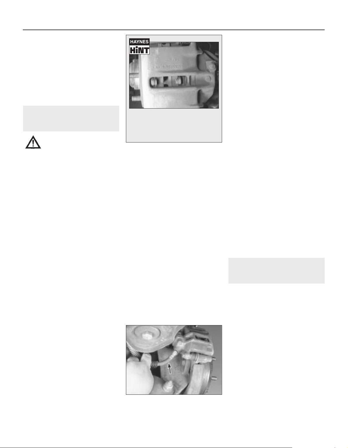
silencer and catalytic converter. If the
components can come in contact with the
body or suspension parts, secure the exhaust
system with new mounts.
5 Check the running condition of the engine
by inspecting inside the end of the tailpipe.
The exhaust deposits here are an indication of
engine state-of-tune. If the pipe is black and
sooty or coated with white deposits, the
engine is in need of a tune-up, including a
thorough fuel system inspection.
11 Braking system - general
check and adjustment
2
Warning: The dust created by
the brake system may contain
asbestos, which is harmful to
your health. Never blow it out
with compressed air and don’t inhale any
of it. An approved filtering mask should be
worn when working on the brakes. Do not,
under any circumstances, use petroleumbased solvents to clean brake parts. Use
brake system cleaner only! Try to use nonasbestos replacement parts whenever
possible.
Note: For detailed photographs of the brake
system, refer to Chapter 9.
1 In addition to the specified intervals, the
brakes should be inspected every time the
wheels are removed or whenever a defect is
suspected. Any of the following symptoms
could indicate a potential brake system
defect: The vehicle pulls to one side when the
brake pedal is depressed; the brakes make
squealing or dragging noises when applied;
brake pedal travel is excessive; the pedal
pulsates; brake fluid leaks, usually onto the
inside of the tyre or wheel.
2 The disc brakes have built-in electrical wear
indicators which cause a warning lamp to
illuminate on the instrument panel when
they’re worn to the renewal point. When the
warning light comes on, replace the pads
immediately or expensive damage to the
discs can result.
3 Loosen the wheel nuts.
4 Raise the vehicle and place it securely on
axle stands.
5 Remove the wheels.
Disc brakes
6 There are two pads (an outer and an inner)
in each caliper. The pads are visible through
inspection holes in each caliper (see Haynes
Hint).
7 Check the pad thickness by looking at each
end of the caliper and through the inspection
hole in the caliper body. If the lining material is
less than the thickness listed in this Chapter’s
Specifications, replace the pads. Note: Keep
in mind that the lining material is riveted or
bonded to a metal backing plate and the metal
portion is not included in this measurement.
8 If it is difficult to determine the exact
thickness of the remaining pad material by the
above method, or if you are at all concerned
about the condition of the pads, remove the
caliper(s), then remove the pads from the
calipers for further inspection (see Chapter 9).
9 Once the pads are removed from the
calipers, clean them with brake cleaner and
re-measure them with a ruler or a vernier
caliper.
10 Measure the disc thickness with a
micrometer to make sure that it still has
service life remaining. If any disc is thinner
than the specified minimum thickness,
replace it (refer to Chapter 9). Even if the disc
has service life remaining, check its condition.
Look for scoring, gouging and burned spots. If
these conditions exist, remove the disc and
have it resurfaced (see Chapter 9).
11 Before refitting the wheels, check all
brake lines and hoses for damage, wear,
deformation, cracks, corrosion, leakage,
bends and twists, particularly in the vicinity of
the rubber hoses at the calipers (see
illustration). Check the clamps for tightness
and the connections for leakage. Make sure
that all hoses and lines are clear of sharp
edges, moving parts and the exhaust system.
If any of the above conditions are noted,
repair, reroute or replace the lines and/or
fittings as necessary (see Chapter 9).
Hydraulic brake servo check
12 Sit in the driver’s seat and perform the
following sequence of tests.
13 Start the engine, run it for about a minute
and turn it off. Then firmly depress the brake
several times - the pedal travel should
decrease with each application.
14 With the brake fully depressed, start the
engine - the pedal should move down a little
when the engine starts.
15 Depress the brake, stop the engine and
hold the pedal in for about 30 seconds - the
pedal should neither sink nor rise.
16 If your brakes do not operate as
described above when the preceding tests
are performed, the brake servo is either in
need of repair or has failed. Refer to Chapter 9
for the removal procedure.
Handbrake
17 Slowly pull up on the handbrake and
count the number of clicks you hear until the
handle is up as far as it will go. The
adjustment should be within the specified
number of clicks listed in this Chapter’s
Specifications. If you hear more or fewer
clicks, it’s time to adjust the handbrake (refer
to Chapter 9).
18 An alternative method of checking the
handbrake is to park the vehicle on a steep hill
with the handbrake set and the transmission
in Neutral (be sure to stay in the vehicle during
this check!). If the handbrake cannot prevent
the vehicle from rolling, it is in need of
adjustment (see Chapter 9). Whenever a fault
is suspected, the brake discs should be
removed and the handbrake assemblies
themselves should be visually inspected.
12 Steering
and suspension check
2
Note: The steering linkage and suspension
components should be checked periodically.
Worn or damaged suspension and steering
linkage components can result in excessive
and abnormal tyre wear, poor ride quality and
vehicle handling and reduced fuel economy.
For detailed illustrations of the steering and
suspension components, refer to Chapter 10.
With the wheels on the ground
1 Park the vehicle on level ground, turn the
engine off and set the handbrake. Check the
tyre pressures and check that the wheel nuts
are tightened to the specified torque.
2 Push down at one corner of the vehicle,
then release it while noting the movement of
the body. It should stop moving and come to
rest in a level position with one or two
bounces. When bouncing the vehicle up and
down, listen for squeaks and noises from the
suspension components.
3 If the vehicle continues to move up-anddown or if it fails to return to its original
1•12 Every 7500 miles or 6 months
11.11 Check along the brake hoses
and at each fitting (arrowed) for
deterioration and cracks
3261 Jaguar XJ6
You will find an inspection hole like this
in each caliper - placing a ruler across
the hole should enable you to determine
the thickness of remaining pad material
for both inner and outer pads
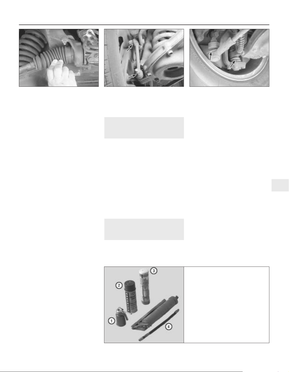
position, a worn or weak shock absorber is
probably the reason.
4 Repeat the above check at each of the
three remaining corners of the vehicle.
Under the vehicle
5 Raise the vehicle with a trolley jack and
support it securely on axle stands. See
“Jacking and towing” for proper jacking
points.
6 Check the shock absorbers for evidence of
fluid leakage. Make sure that any fluid noted is
from the shocks and not from any other
source. Also check the rubber mounts at each
end for deterioration If the shock absorbers
fail any of the tests above replace the shocks
as a set.
7 Check the tyres for irregular wear patterns
and proper inflation. See “Weekly checks” for
information regarding tyre wear.
8 Inspect the universal joint between the
steering shaft and the steering gear housing.
Check the steering gear housing for grease
leakage. Make sure that the dust seals and
boots are not damaged and that the boot
clamps are not loose (see illustration). Check
the steering linkage for looseness or damage.
Look for loose bolts, broken or disconnected
parts and deteriorated rubber bushings on all
suspension and steering components (see
illustration). While an assistant turns the
steering wheel from side to side, check the
steering components for free movement,
chafing and binding. If the steering
components do not seem to be reacting with
the movement of the steering wheel, try to
determine where the slack is located.
9 Check the balljoints moving each lower arm
up and down with a crowbar to ensure that its
balljoint has no play. If any balljoint does have
play, replace it. See Chapter 10 for the front
balljoint renewal procedure. Check the tie-rod
ends for excessive play.
10 Inspect the balljoint and tie-rod end boots
for damage and leaking grease (see
illustration. Replace the balljoints and tie-rod
ends with new ones if they are damaged (see
Chapter 10).
13 Seat belt check
1
1 Check the seat belts, buckles, latch plates
and guide loops for any obvious damage or
signs of wear.
2 Make sure the seat belt reminder light
comes on when the key is turned on.
3 The seat belts are designed to lock up
during a sudden stop or impact, yet allow free
movement during normal driving. The
retractors should hold the belt against your
chest while driving and rewind the belt when
the buckle is unlatched.
4 If any of the above checks reveal problems
with the seat-belt system, replace parts as
necessary. Note: Check with your local dealer
service department; the seat belt system
should be covered under the factory warranty.
14 General lubrication
2
1 Obtain a good quality, multi-purpose
lithium-base grease. You’ll also need a grease
gun and other materials to properly lubricate
the chassis (see illustration). Occasionally
plugs will be installed rather than grease
fittings. If so, grease fittings will have to be
purchased and installed.
2 Look under the car and see if grease fittings
or plugs are installed. If there are plugs,
remove them and buy grease fittings, which
will thread into the component. A dealer or
motor factors will be able to supply the
correct fittings. Straight, as well as angled,
fittings are available.
3 For easier access under the car, raise it with
a jack and place axle stands under the
chassis. Make sure it’s safely supported by
the stands. If the wheels are to be removed at
this interval for tyre rotation or brake
inspection, loosen the wheel nuts slightly
while the car is still on the ground.
4 Before beginning, force a little grease out of
the nozzle to remove any dirt from the end of
the gun. Wipe the nozzle clean with a rag.
5 With the grease gun and plenty of clean
rags, crawl under the car and begin
lubricating all the front suspension parts that
are equipped with a grease fitting.
6 Lubricate the rear driveshafts (see
illustration). Wipe each fitting clean and push
the nozzle firmly over it. Pump the gun until
grease is expelled from the U-joint cap seal.
7 Wipe away any excess grease from the
components and the grease fitting. Repeat
the procedure for the remaining fittings.
Every 7500 miles or 6 months 1•13
1
14.1 Materials required for chassis
and body lubrication
3261 Jaguar XJ6
12.8a Check the steering gear dust boots
for cracks and leaking steering fluid
12.8b Check the anti-roll bar bushings
(arrowed) for deterioration at the front and
the rear of the vehicle
12.10 Inspect the balljoint and tie-rod end
boots for tears - tears or damage in either
boot will allow contamination of the grease
which will lead to premature failure
1 Engine oil - Light engine oil in a can like
this can be used for door and bonnet
hinges
2 Graphite spray - Used to lubricate lock
cylinders
3 Grease - Grease, in a variety of types and
weights, is available for use in a grease
gun.
4 Grease gun - A common grease gun,
shown here with a detachable hose and
nozzle, is needed for chassis lubrication.
After use, clean it thoroughly
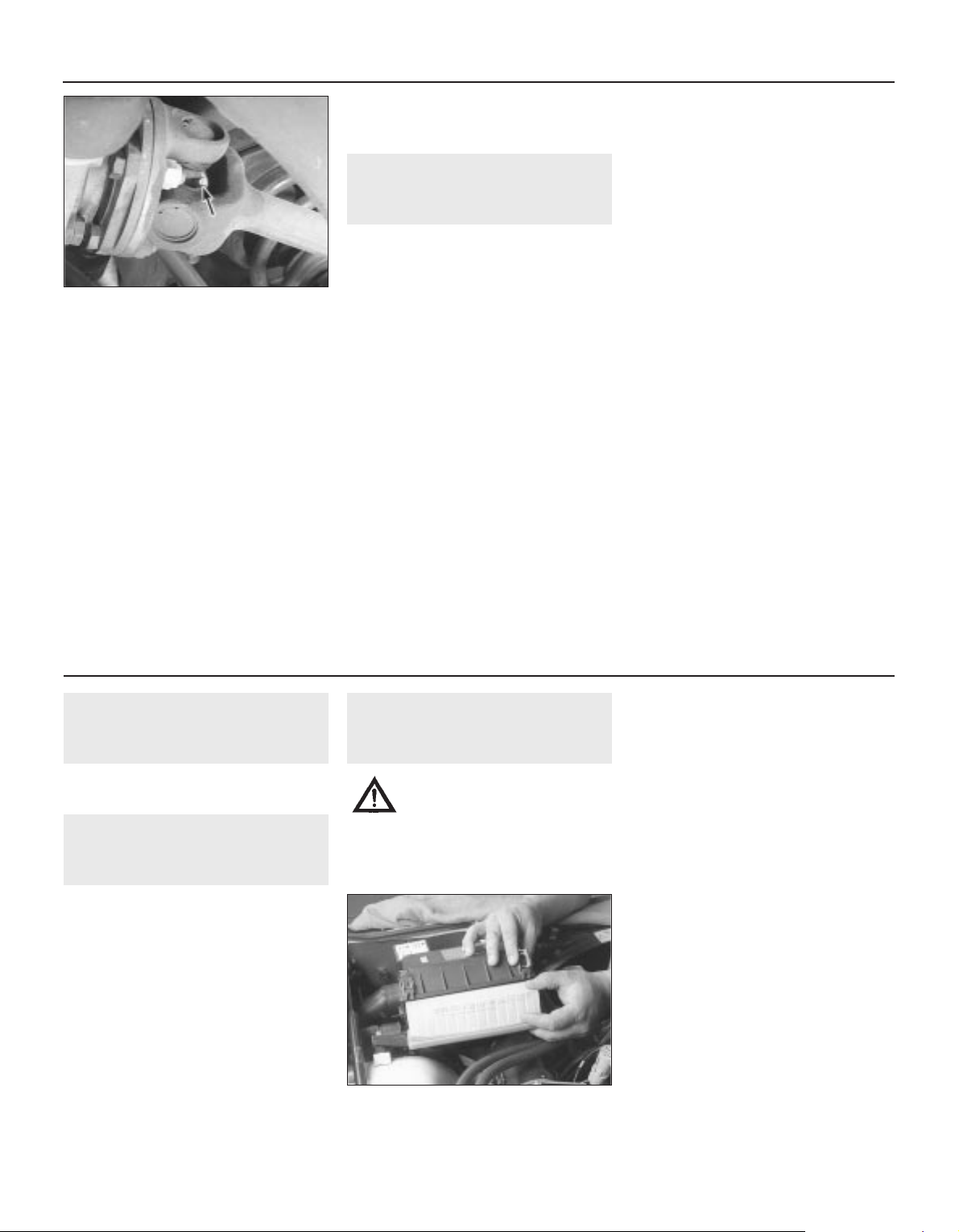
16 Spark plug renewal
2
Refer to Section 4, renewing the plugs
regardless of their apparent condition.
17 Air cleaner element renewal
1
1 The air filter is located inside a housing at
the left side of the engine compartment. To
remove the air filter, release the four spring
clips that secure the two halves of the air
cleaner housing together, then lift the cover
up and remove the air filter element (see
illustration).
Caution: Never drive the car with the air
cleaner removed. Excessive engine wear
could result and backfiring could even
cause a fire under the bonnet.
2 Wipe out the inside of the air cleaner
housing.
3 Place the new filter into the air cleaner
housing, making sure it seats properly.
4 Refitting the cover is the reverse of removal.
18 Fuel filter renewal
2
Warning: Petrol is extremely
flammable, so take extra
precautions when you work on
any part of the fuel system.
Don’t smoke or allow open flames or bare
light bulbs near the work area, and don’t
work in a garage where a natural gas-type
appliance (such as a water heater or
clothes dryer) with a pilot light is present.
Since petrol is carcinogenic, wear latex
gloves when there’s a possibility of being
exposed to fuel, and, if you spill any fuel on
your skin, rinse it off immediately with soap
and water. Mop up any spills immediately
and do not store fuel-soaked rags where
they could ignite. The fuel system is under
constant pressure, so, if any fuel lines are
to be disconnected, the fuel pressure in
the system must be relieved first (see
Chapter 4 for more information). When you
perform any kind of work on the fuel
system, wear safety glasses and have a
Class B type fire extinguisher on hand.
1 The canister type filter is mounted
underneath the car on the passenger’s side
frame rail just in front of the left rear tyre.
2 Depressurise the fuel system (refer to
Chapter 4), then disconnect the cable from
the negative terminal of the battery.
3 On 1988 to 1990 models, detach the banjo
bolt from the outlet side of the filter then
remove the union from the inlet side of the
filter. Unscrew the filter mounting bolt and
remove the filter (see illustration).
4 On 1991 to 1994 models, the fuel filter has
quick-disconnect fittings that do not require
8 Clean and lubricate the handbrake cable,
along with the cable guides and levers. This
can be done by smearing some of the chassis
grease onto the cable and its related parts
with your fingers.
9 Open the bonnet and smear a little chassis
grease on the bonnet latch mechanism. Have
an assistant pull the bonnet release lever from
inside the car as you lubricate the cable at the
latch.
10 Lubricate all the hinges (door, bonnet,
etc.) with engine oil to keep them in proper
working order.
11 The key lock cylinders can be lubricated
with spray graphite or silicone lubricant, which
is available at motor factors.
12 Lubricate the door weather-stripping with
silicone spray. This will reduce chafing and
retard wear.
15 Road test
1
Instruments and electrical
equipment
1 Check the operation of all instruments and
electrical equipment.
2 Make sure that all instruments read
correctly, and switch on all electrical
equipment in turn, to check that it functions
properly.
Steering and suspension
3 Check for any abnormalities in the steering,
suspension, handling or road “feel”.
4 Drive the car, and check that there are no
unusual vibrations or noises.
5 Check that the steering feels positive, with
no excessive “sloppiness”, or roughness, and
check for any suspension noises when
cornering and driving over bumps.
Drivetrain
6 Check the performance of the engine and
transmission, listening for any unusual noises.
7 Make sure that the engine runs smoothly
when idling, and that there is no hesitation
when accelerating.
8 Check that the gear changing action of the
transmission is smooth and progressive and
that the drive is taken up smoothly from a
standing start.
Braking system
9 Make sure that the car does not pull to one
side when braking, and that the wheels do not
lock prematurely when braking hard.
10 Check that there is no vibration through
the steering when braking.
11 Check that the handbrake operates
correctly without excessive movement of the
lever, and that it holds the car stationary on a
slope.
12 Test the operation of the brake servo unit
as follows. With the engine off, depress the
footbrake four or five times to exhaust the
vacuum. Hold the brake pedal depressed, then
start the engine. As the engine starts, there
should be a noticeable “give” in the brake
pedal as vacuum builds up. Allow the engine to
run for at least two minutes, and then switch it
off. If the brake pedal is depressed now, it
should be possible to detect a hiss from the
servo as the pedal is depressed. After about
four or five depressions, no further hissing
should be heard, and the pedal should feel
considerably harder.
1•14 Every 7500 miles or 6 months
17.1 Detach the clips and separate the
cover, then slide the filter element out of
the housing
3261 Jaguar XJ6
14.6 Grease fittings for the rear
driveshafts are located in the centre
on each U-joint
Every 15 000 miles (24 000 km) or 12 months

hand tools to remove. Simply slide back the
locking collars and remove the inlet and outlet
fuel lines (see illustration). Detach the filter
mounting bracket and discard the old filter in
a proper container.
5 Note the direction of the arrow on the
outside of the filter; it should be pointed
towards the front of the car. Make sure the
new filter is installed so that it’s facing the
proper direction. Note: Always refit new
copper washers where equipped.
6 Refit the inlet and outlet fittings then tighten
the filter mounting bracket. Reconnect the
battery cable, start the engine and check for
leaks.
19 Ignition system check
2
1 The spark plug leads should be checked
whenever new spark plugs are installed.
2 Begin this procedure by making a visual
check of the spark plug leads while the engine
is running. In a darkened garage (make sure
there is adequate ventilation) start the engine
and observe each plug lead. Be careful not to
come into contact with any moving engine
parts. If there is a break in the lead, you will
see arcing or a small spark at the damaged
area. If arcing is noticed, make a note to
obtain new leads, then allow the engine to
cool and check the distributor cap and rotor.
3 The spark plug leads should be inspected
one at a time to prevent mixing up the order,
which is essential for proper engine operation.
Each original plug lead should be numbered
to help identify its location. If the number is
illegible, a piece of tape can be marked with
the correct number and wrapped around the
plug lead.
4 Disconnect the plug lead from the spark
plug. A removal tool can be used for this
purpose or you can grasp the rubber boot,
twist the boot half a turn and pull the boot
free. Do not pull on the lead itself.
5 Check inside the boot for corrosion, which
will look like a white crusty powder.
6 Push the lead and boot back onto the end
of the spark plug. It should fit tightly onto the
end of the plug. If it doesn’t, remove the lead
and use pliers to carefully crimp the metal
connector inside the lead boot until the fit is
snug.
7 Using a clean rag, wipe the entire length of
the lead to remove built-up dirt and grease.
Once the lead is clean, check for burns,
cracks and other damage. Do not bend the
lead sharply, because the conductor might
break.
8 Disconnect the spark plug lead from the
distributor cap. Again, pull only on the rubber
boot. Check for corrosion and a tight fit.
Reinsert the lead in the distributor cap.
9 Inspect the remaining spark plug leads,
making sure that each one is securely
fastened at the distributor and spark plug
when the check is complete.
10 If new spark plug leads are required,
purchase a set for your specific engine model.
Remove and replace the leads one at a time
to avoid mix-ups in the firing order.
11 Detach the distributor cap by unsnapping
the cap retaining clips. Look inside it for
cracks, carbon tracks and worn, burned or
loose contacts (see illustrations).
12 Pull the rotor off the distributor shaft and
examine it for cracks and carbon tracks (see
illustrations). Replace the cap and rotor if any
damage or defects are noted.
13 It is common practice to refit a new cap
and rotor whenever new spark plug leads are
installed. When refitting a new cap, remove
the leads from the old cap one at a time and
attach them to the new cap in the exact same
location Note: If an accidental mix-up occurs,
refer to the firing order Specifications at the
beginning of this Chapter.
Every 15 000 miles or 12 months 1•15
1
19.11a Unsnap the distributor cap
retaining clips - pull the cap up and away
to access the rotor
19.11b Shown here are some of the
common defects to look for when
inspecting the distributor cap (typical cap
shown). If in doubt about its condition,
fit a new one
19.12a Pull off the rotor (arrowed) and
inspect it thoroughly
19.12b Check the ignition rotor for wear
and corrosion as indicated here (if in doubt
about its condition, buy a new one)
3261 Jaguar XJ6
18.3 Remove the banjo bolt from the
outlet side (B), detach the fitting from the
inlet side (A) and unscrew the filter
mounting bolt (C)
18.4 On 1991 to 1994 models, slide back
the locking collars and remove the inlet
and outlet fuel lines

20 Crankcase ventilation
system check
1
Refer to Chapter 6.
21 Drivebelt check and renewal
2
Check
1 The drivebelts, or V-belts as they are
sometimes called, are located at the front of
the engine and play an important role in the
overall operation of the vehicle and its
components. Due to their function and
material make-up, the belts are prone to
failure after a period of time and should be
inspected and adjusted periodically to prevent
major engine damage.
2 The number of belts used on a particular
vehicle depends on the accessories installed.
The main belt transmits power from the
crankshaft to the water pump, alternator and
the power steering pump. The second belt
transmits power from the crankshaft to the air
conditioning compressor.
3 With the engine off, open the bonnet and
locate the drivebelts. With a flashlight, check
each belt for separation of the adhesive
rubber on both sides of the core, core
separation from the belt side, a severed core,
separation of the ribs from the adhesive
rubber, cracking or separation of the ribs, and
torn or worn ribs or cracks in the inner ridges
of the ribs (see illustrations). Also check for
fraying and glazing, which gives the belt a
shiny appearance. Both sides of the belt
should be inspected, which means you will
have to twist the belt to check the underside.
Use your fingers to feel the belt where you
can’t see it. If any of the above conditions are
evident, replace the belt (go to paragraph 7).
4 Check the belt tension by pushing firmly on
the belt with your thumb at a distance halfway
between the pulleys and note how far the belt
can be pushed (deflected). Measure this
deflection with a ruler (see illustration). As a
rule of thumb, if the distance from pulley
centre-to- pulley centre is between 7 and
11 inches, the belt should deflect 1/4-inch. If
the belt travels between pulleys spaced 12 to
16 inches apart, the belt should deflect
1/2-inch for a V-belt or 1/4-inch for a
serpentine belt.
Adjustment
5 There are two belt tensioning mechanisms.
The first one adjusts the air conditioning
compressor belt, which is accessible from
underneath the car. The second tensioning
mechanism is above the alternator - it adjusts
the tension on the main belt (the water pump,
alternator and power steering pump belt).
6 The air conditioning compressor and the
alternator each have a belt tensioning
mechanism and pivot bolt(s) which must be
loosened slightly to enable you to move the
component (see illustrations).
7 After the bolts have been loosened, belt
tension can be adjusted by either loosening or
tightening the locknuts on the belt tensioning
adjustment rod (see illustration 21.6a and b).
Move the component away from the engine to
tighten the belt or toward the engine to loosen
the belt.
8 Measure the belt tension using the method
described in paragraph 4. Repeat this
procedure until the drivebelt is adjusted
properly.
Renewal
9 To replace a belt, loosen the drivebelt
adjustment rod and pivot bolt as described
above, slip the belt off the crankshaft pulley
and remove it. If you are replacing the
alternator/power steering pump belt, you’ll
have to remove the air conditioning
1•16 Every 15 000 miles or 12 months
21.3a Small cracks in the underside of a
serpentine belt are acceptable -
lengthwise cracks, or missing pieces, are
cause for replacement
21.3b Here are some of the more common
problems associated with V-belts (check
the belts very carefully to prevent an
untimely breakdown)
21.4 Measuring drivebelt deflection with a
straightedge and ruler
21.6a To adjust the alternator/power
steering drivebelt, loosen the outer locknut
(arrowed) and the alternator pivot bolt turn the inner locknut anti-clockwise to
loosen or clockwise to tighten the belt
21.6b To adjust the air conditioning
compressor drivebelt, loosen the outer
locknut (arrowed) and the compressor
pivot bolts - turn the inner locknut anti-
clockwise to loosen or clockwise to
tighten the belt
3261 Jaguar XJ6

compressor belt first because of the way they
are arranged on the crankshaft pulley.
Because of this and because belts tend to
wear out more or less together, it is a good
idea to replace both belts at the same time.
Mark each belt and its appropriate pulley
groove so the new belts can be installed in
their proper positions.
10 Take the old belts to the parts store in
order to make a direct comparison for length,
width and design.
11 After replacing a ribbed drivebelt, make
sure that it fits properly in the ribbed grooves
in the pulleys (see illustration). It is essential
that the belt be properly centred.
12 Adjust the belt(s) in accordance with the
procedure outlined above.
22 Front wheel bearing check
and adjustment
3
Check and repack
1 In most cases the front wheel bearings will
not need servicing until the brake pads are
changed. However, the bearings should be
checked whenever the front of the vehicle is
raised for any reason. Several items, including
a torque wrench and special grease, are
required for this procedure (see illustration).
2 With the vehicle securely supported on axle
stands, spin each wheel and check for noise,
rolling resistance and freeplay.
3 Grasp the top of each tyre with one hand
and the bottom with the other. Move the
wheel in-and-out on the spindle. If there’s any
noticeable movement, the bearings should be
checked and then repacked with grease or
renewed if necessary.
4 Remove the wheel.
5 Remove the brake caliper (see Chapter 9)
and hang it out of the way on a piece of wire.
A wood block of the appropriate width can be
slid between the brake pads to keep them
separated, if necessary. Also remove the
brake disc.
6 Pry the dust cap out of the hub using a
screwdriver or a hammer and chisel (see
illustration).
7 Straighten the bent ends of the cotter pin,
then pull the cotter pin out of the nut lock (see
illustration). Discard the cotter pin and use a
new one during reassembly.
8 Remove the locknut, nut and washer from
the end of the spindle.
9 Pull the hub out slightly, then push it back
into its original position. This should force the
outer bearing off the spindle enough so it can
be removed (see illustration).
10 Pull the hub off the spindle. Note:
Sometimes the inner wheel bearing and
grease seal remain attached to the spindle.
Grasp the back of the seal with both hands
and pull forward to remove them.
11 If the grease seal is not already detached
from the hub, use a screwdriver to pry the seal
out of the rear of the hub. As this is done, note
how the seal is installed.
12 If the inner wheel bearing is not already
detached from the hub, remove it at this time.
13 Use solvent to remove all traces of the old
grease from the bearings, hub and spindle. A
small brush may prove helpful; however make
sure no bristles from the brush embed
themselves inside the bearing rollers. Allow
the parts to air dry.
14 Carefully inspect the bearings for cracks,
heat discoloration, worn rollers, etc. Check
the bearing races inside the hub for wear and
damage. If the bearing races are defective,
the hubs should be taken to a machine
workshop with the facilities to remove the old
races and press new ones in. Note that the
bearings and races come as matched sets
Every 15 000 miles or 12 months 1•17
1
22.1 Tools and materials needed for front
wheel bearing maintenance
1 Hammer
2 Grease - High-temperature grease that is
formulated specially for front wheel
bearings should be used
3 Wood block - If you have a scrap piece
of 2x4, it can be used to drive the new
seal into the hub
4 Needle-nose pliers - Used to straighten
and remove the cotter pin in the spindle
5 Torque wrench - This is very important in
this procedure; if the bearing is too tight,
the wheel won’t turn freely - if it’s too
loose, the wheel will “wobble” on the
spindle. Either way, it could mean
extensive damage
6 Screwdriver - Used to remove the seal
from the hub (a long screwdriver is
preferred)
7 Socket/breaker bar - Needed to loosen the
nut on the spindle if it’s extremely tight
8 Brush - Together with some clean
solvent, this will be used to remove old
grease from the hub and spindle
22.6 Dislodge the dust cap by working
around the outer circumference with a
hammer and chisel
22.7 Remove the cotter pin and discard it use a new one when the hub is reinstalled
22.9 Pull the hub assembly forward
slightly - then push it back into position to
dislodge the outer wheel bearing
3261 Jaguar XJ6
21.11 When refitting ribbed (serpentine)
drivebelts, make sure the belt is centred
between the pulley edges (arrowed) - it
must not overlap either edge of the pulley

and old bearings should never be installed on
new races.
15 Use high-temperature front wheel bearing
grease to pack the bearings. Work the grease
completely into the bearings, forcing it
between the rollers, cone and cage from the
back side (see illustration).
16 Apply a thin coat of grease to the spindle
at the outer bearing seat, inner bearing seat,
shoulder and seal seat.
17 Put a small quantity of grease inboard of
each bearing race inside the hub. Using your
finger, form a dam at these points to provide
extra grease availability and to keep thinned
grease from flowing out of the bearing (see
illustration).
18 Place the grease-packed inner bearing
into the rear of the hub and put a little more
grease outboard of the bearing.
19 Place a new seal over the inner bearing
and tap the seal evenly into place until it’s
flush with the hub (see illustration).
20 Carefully place the hub assembly onto the
spindle and push the grease-packed outer
bearing into position (see illustration).
Adjustment
21 Refit the washer and spindle nut. Tighten
the nut only slightly (no more than 16Nm/12
lbf ft of torque).
22 Rotate the hub slowly in a forward
direction while tightening the spindle nut to
approximately 27Nm (20 lbf ft) to seat the
bearings. Remove any grease or burrs which
could cause excessive bearing play later.
23 Loosen the spindle nut 1/4-turn, then
using your hand (not a spanner of any kind),
tighten the nut until it’s snug. Refit the nut lock
and a new cotter pin through the hole in the
spindle and the slots in the nut lock. If the
nut lock slots don’t line up, remove the nut
lock and turn it slightly until they do (see
illustration).
24 Bend the ends of the cotter pin until
they’re flat against the nut. Cut off any extra
length which could interfere with the dust cap.
25 Refit the dust cap, tapping it into place
with a hammer.
26 Refit the brake disc and caliper in the
reverse order of removal (see Chapter 9).
27 Refit the wheel on the hub and tighten the
wheel nuts.
28 Grasp the top and bottom of the tyre and
check the bearings in the manner described
earlier in this Section.
29 Lower the vehicle and tighten the wheel
nuts to the torque listed in this Chapter’s
Specifications.
23 Propshaft check
2
1 Referring to Chapter 8, check the propshaft
centre bearing, universal joint and flexible
coupling for signs of wear or damage and
check that the propshaft fixings are tightened
to the specified torque.
24 Front wheel alignment check
5
1 Accurate wheel alignment requires access
to specialised test equipment and as such
should be entrusted to a suitably equipped
Jaguar dealer or a tyre specialist (refer to
Chapter 10).
25 Headlight beam check
5
1 Accurate adjustment of the headlight beam
is only possible using optical beam-setting
equipment, and this work should therefore be
carried out by a Jaguar dealer or garage with
the necessary facilities (see Chapter 12).
1•18 Every 15 000 miles or 12 months
22.15 Work the grease completely into the
bearing rollers
22.17 Apply a thin layer of grease to the
inner and outer bearing races
22.19 After refitting the inner wheel
bearing into the hub - press the grease
seal into place
22.20 Refit the hub assembly onto the
spindle - then push the grease-packed
outer bearing into position
22.23 Position the nut lock on the spindle
nut so that it lines up with the cotter pin
hole - DO NOT loosen the spindle nut from
its snug position
3261 Jaguar XJ6

26 Automatic transmission fluid
and filter renewal
2
1 At the specified time intervals, the
transmission fluid should be drained and
renewed. Since the fluid will remain hot long
after driving, perform this procedure only after
the engine has cooled down completely.
2 Before beginning work, purchase the
specified transmission fluid and a new filter.
3 Other tools necessary for this job include
axle stands to support the vehicle in a raised
position, a drain pan capable of holding at
least eight pints, newspapers and clean rags.
4 Raise the vehicle and support it securely on
axle stands.
5 Place the drain pan under the drain plug in
the bottom of the transmission sump pan.
Remove the plug and allow the fluid to drain
(see illustration).
6 Refit the drain plug, then move the drain
pan underneath the dipstick tube. Loosen the
dipstick tube collar and let the remaining fluid
drain (see illustrations).
7 Remove the sump pan mounting bolts and
brackets (see illustration).
8 Detach the sump pan from the transmission
and lower it, keeping it as horizontal as
possible in order not to spill too much of the
remaining fluid (see illustration).
9 Drain the remaining fluid from the
transmission sump pan, clean it with solvent
and dry it with compressed air. Be sure to
clean the metal filings from the magnet, if
equipped.
10 Remove the screws and detach the filter
from the valve body (see illustrations).
11 Refit the new O-ring and filter, being sure
to tighten the bolts securely.
12 Carefully clean the fluid pan-totransmission sealing surface.
13 Make sure the gasket surface on the
transmission sump pan is completely clean,
then refit the gasket. Put the sump pan in
place against the transmission and refit the
brackets and bolts. working around the sump
pan, tighten each bolt a little at a time until the
torque listed in this Chapter’s Specifications
is reached. Don’t overtighten the bolts!
Connect the dipstick tube and tighten the
collar securely.
14 Lower the vehicle and add the specified
amount of fluid through the filler tube (see
Section 8).
15 With the transmission in Park and the
handbrake set, run the engine at fast idle, but
don’t race it.
16 Move the gear selector through each
position, and then back to Park. Check the
fluid level.
17 Be sure to check underneath the car for
any leaks after the first few miles of driving.
Every 30 000 miles (48 000 km) or 2 years
Every 30 000 miles or 2 years 1•19
1
26.6a Unscrew the dipstick tube collar 26.6b Detach the tube and let the
remaining fluid drain
26.7 Use a socket and extension to
remove the transmission sump pan bolts
and brackets
26.8 Lower the sump pan from the
transmission
26.10a Use a Torx-head driver to remove
the filter bolts (arrowed) . . .
3261 Jaguar XJ6
26.5 Using an Allen spanner remove the
drain plug located in the bottom of the
transmission sump pan
26.10b . . . then remove the fluid filter from
the transmission
26.10c Be sure to remove the old O-ring
from the transmission - always use a new
O-ring when replacing the filter

30 Coolant renewal
2
Warning: Do not allow engine
coolant (antifreeze) to come in
contact with your skin or painted
surfaces of the vehicle. Rinse off
spills immediately with plenty of water.
Antifreeze is highly toxic if ingested. Never
leave antifreeze laying around in an open
container or in puddles on the floor;
children and pets are attracted by it’s
sweet smell and may drink it. Check with
local authorities about disposing of used
antifreeze. Your local authority may have
collection centres which will see that
antifreeze is disposed of safely.
1 Periodically, the cooling system should be
drained, flushed and refilled to replenish the
antifreeze mixture and prevent formation of
rust and corrosion, which can impair the
performance of the cooling system and
cause engine damage. When the cooling
system is serviced, all hoses and the radiator
cap should be checked and renewed if
necessary.
Draining
2 Apply the handbrake and block the wheels.
If the vehicle has just been driven, wait several
hours to allow the engine to cool down before
beginning this procedure.
3 Remove the expansion tank pressure cap
(see illustration).
4 Move a large container under the radiator
drain to catch the coolant. Then using a large
screwdriver, open the radiator drain plug and
direct the coolant into the container (see
illustration).
27 Differential oil renewal
2
1 Drive the car for several miles to warm up
the differential lubricant, then raise the car
and support it securely on axle stands.
2 Move a drain pan, rags, newspapers and
the required tools under the car.
3 Remove the check/fill plug from the
differential. If necessary refer to Section 9 for
the check/fill plug location.
4 With the drain pan under the differential,
use a ratchet and socket to loosen the drain
plug (see illustration). Note: A special pipe
plug socket may be required to complete this
procedure.
5 Once loosened, carefully unscrew it with
your fingers until you can remove it from the
case. Since the lubricant will be hot, wear a
rubber glove to prevent burns.
6 Allow all of the oil to drain into the pan, then
replace the drain plug and tighten it securely.
7 Refer to Section 9 and fill the differential
with lubricant.
8 Refit the fill plug and tighten it securely.
9 Lower the vehicle. Check for leaks at the
drain plug after the first few miles of driving.
28 Brake fluid renewal
2
Warning: Brake fluid can harm
your eyes and damage painted
surfaces, so use extreme
caution when handling or
pouring it. Do not use brake fluid that has
been standing open or is more than one
year old. Brake fluid absorbs moisture from
the air. Excess moisture can cause a
dangerous loss of braking effectiveness.
1 At the specified time intervals, the brake
fluid should be drained and renewed. Since
the brake fluid may drip or splash when
pouring it, place plenty of rags around the
master cylinder to protect any surrounding
painted surfaces.
2 Before beginning work, purchase the
specified type of brake fluid.
3 Remove the cap from the master cylinder
reservoir.
4 Using a hand suction pump or similar
device, withdraw the fluid from the master
cylinder reservoir.
5 Add new fluid to the master cylinder until it
rises to the base of the filler neck.
6 Bleed the brake system as described in
Chapter 9 at all four brakes until new and
uncontaminated fluid flows from the bleed
screw.
7 Refill the master cylinder with fluid and
check the operation of the brakes. The pedal
should feel solid when depressed, with no
sponginess.
Warning: Do not drive the car if
you are in any doubt about the
braking system.
1•20 Every 30 000 miles or 2 years
27.4 The differential drain plug (arrowed)
is accessible through a hole located in the
middle of the differential support brace
30.3 Push the expansion tank pressure
cap downward and rotate anti-clockwise -
never remove it when the engine is hot!
3261 Jaguar XJ6
Every 60 000 miles (96 000 km)
29 Handbrake shoes check
2
1 Remove the rear discs and inspect the
handbrake shoes as described in Chapter 9. If
the shoes are worn or damaged they must be
renewed.
Warning: The dust created by
the brake system may contain
asbestos, which is harmful to
your health. Never blow it out
with compressed air and don’t inhale any
of it. An approved filtering mask should be
worn when working on the brakes. Do not,
under any circumstances, use petroleumbased solvents to clean brake parts. Use
brake system cleaner only! Try to use nonasbestos replacement parts whenever
possible.
Every 2 years, regardless of mileage

5 After the coolant stops flowing out of the
radiator, move the container under the engine
block drain plug. Remove the plug and let the
coolant in the block to drain (see illustration).
6 While the coolant is draining from the
engine block, check the condition of the
radiator hoses, heater hoses and clamps
(refer to Section 7 if necessary).
7 Replace any damaged clamps or hoses
(see Chapter 3).
Flushing
8 Once the system is completely drained,
flush the radiator with fresh water from a
garden hose until water runs clear at the drain.
The flushing action of the water will remove
sediments from the radiator but will not
remove more serious rust and scale from the
engine and cooling tube surfaces.
9 These deposits can be removed by using
proprietary chemical cleaners. It should be
stressed, however, that these should only
need to be used if the system has been
neglected. Follow the procedure outlined in
their manufacturer’s instructions. If the
radiator is severely corroded, damaged or
leaking, it should be removed (see Chapter 3)
and taken to a radiator repair workshop.
10 On 1988 and 1989 models remove the
overflow hose from the coolant recovery
reservoir. Drain the reservoir and flush it with
clean water, then reconnect the hose (see
Chapter 3).
Refilling
11 Close and tighten the radiator drain. Refit
and tighten the engine block drain plugs.
12 Make sure the heater temperature control
is in the maximum heat position.
13 Slowly refill the expansion tank with a
mixture of antifreeze and water until the
coolant reaches the base of the filler neck.
14 Leave the expansion tank pressure cap
off and run the engine in a well-ventilated area
until the thermostat opens (coolant will begin
flowing through the radiator and the upper
radiator hose will become hot). Race the
engine two or three times under no load.
15 Turn the engine off and let it cool. Add
more coolant mixture to bring the level back
up to the base of the filler neck.
16 Squeeze the upper radiator hose to expel
air, then add more coolant mixture if
necessary. Refit the expansion tank pressure
cap.
17 Start the engine, allow it to reach normal
operating temperature and check for leaks.
Every 2 years 1•21
1
3261 Jaguar XJ6
30.4 The radiator drain fitting (arrowed)
located at the bottom of the radiator
30.5 The block drain plug (arrowed) is
located on the right side of the block

3261 Jaguar XJ6
2A
Chapter 2 Part A
Engine in-car repair procedures
General
Cylinder numbers (front to rear) . . . . . . . . . . . . . . . . . . . . . . . . . . . . . . . 1-2-3-4-5-6
Firing order . . . . . . . . . . . . . . . . . . . . . . . . . . . . . . . . . . . . . . . . . . . . . . . 1-5-3-6-2-4
Displacement:
3.2 litre engine . . . . . . . . . . . . . . . . . . . . . . . . . . . . . . . . . . . . . . . . . . 3239 cc
3.6 litre engine . . . . . . . . . . . . . . . . . . . . . . . . . . . . . . . . . . . . . . . . . . 3590 cc
4.0 litre engine . . . . . . . . . . . . . . . . . . . . . . . . . . . . . . . . . . . . . . . . . . 3980 cc
Bore . . . . . . . . . . . . . . . . . . . . . . . . . . . . . . . . . . . . . . . . . . . . . . . . . 91.0 mm (3.583 inches)
Stroke:
3.2 litre engine . . . . . . . . . . . . . . . . . . . . . . . . . . . . . . . . . . . . . . . . . . 83.0 mm (3.268 inches)
3.6 litre engine . . . . . . . . . . . . . . . . . . . . . . . . . . . . . . . . . . . . . . . . . . 92.0 mm (3.622 inches)
4.0 litre engine . . . . . . . . . . . . . . . . . . . . . . . . . . . . . . . . . . . . . . . . . . 102.0 mm (4.016 inches)
Camshafts and lifters
Journal diameter . . . . . . . . . . . . . . . . . . . . . . . . . . . . . . . . . . . . . . . . . . 26.9370 to 26.9494 mm (1.0605 to 1.0610 inches)
Bearing oil clearance . . . . . . . . . . . . . . . . . . . . . . . . . . . . . . . . . . . . . . . 0.037 to 0.063 mm (0.0014 to 0.0024 inch)
Runout limit . . . . . . . . . . . . . . . . . . . . . . . . . . . . . . . . . . . . . . . . . . . . . . . 0.0406 mm (0.0016 inch)
Lobe lift (maximum variation between lobes) . . . . . . . . . . . . . . . . . . . . . 0.0127 mm (0.005 inch)
Valve lifter
Diameter . . . . . . . . . . . . . . . . . . . . . . . . . . . . . . . . . . . . . . . . . . . . . . . 33.34 to 33.35 mm (1.3126 to 1.3130 inches)
Oil clearance . . . . . . . . . . . . . . . . . . . . . . . . . . . . . . . . . . . . . . . . . . . . 0.020 to 0.050 mm (0.0008 to 0.0020 inch)
Valve clearances . . . . . . . . . . . . . . . . . . . . . . . . . . . . . . . . . . . . . . . . . . . 0.30 to 0.36 mm (0.012 to 0.014 inch)
Oil pump
Outer rotor to body clearance, maximum . . . . . . . . . . . . . . . . . . . . . . . 0.2 mm (0.0079 inch)
Outer rotor OD . . . . . . . . . . . . . . . . . . . . . . . . . . . . . . . . . . . . . . . . . . . . 69.774 to 69.825 mm (2.7470 to 2.7490 inches)
Rotor thickness, inner and outer . . . . . . . . . . . . . . . . . . . . . . . . . . . . . . 27.962 to 27.975 mm (1.1008 to 1.1013 inches)
Clearance over rotors, maximum . . . . . . . . . . . . . . . . . . . . . . . . . . . . . . 0.1 mm (0.0039 inch)
Auxiliary shaft - renewal . . . . . . . . . . . . . . . . . . . . . . . . . . . . . . . . . . . 9
Camshafts and lifters - removal, inspection and refitting . . . . . . . . . 10
CHECK ENGINE light . . . . . . . . . . . . . . . . . . . . . . . . . . . See Chapter 6
Crankshaft front oil seal - renewal . . . . . . . . . . . . . . . . . . . . . . . . . . . 7
Crankshaft rear oil seal - renewal . . . . . . . . . . . . . . . . . . . . . . . . . . . 15
Cylinder compression check . . . . . . . . . . . . . . . . . . . . See Chapter 2B
Cylinder head - removal and refitting . . . . . . . . . . . . . . . . . . . . . . . . 11
Drivebelt check, adjustment and renewal . . . . . . . . . . . See Chapter 1
Driveplate - removal and refitting . . . . . . . . . . . . . . . . . . . . . . . . . . . 14
Engine mounts - check and renewal . . . . . . . . . . . . . . . . . . . . . . . . . 16
Engine oil and filter change . . . . . . . . . . . . . . . . . . . . . . See Chapter 1
Engine overhaul - general information . . . . . . . . . . . . . See Chapter 2B
Engine - removal and refitting . . . . . . . . . . . . . . . . . . . See Chapter 2B
Exhaust manifolds - removal and refitting . . . . . . . . . . . . . . . . . . . . . 6
General information . . . . . . . . . . . . . . . . . . . . . . . . . . . . . . . . . . . . . . 1
Intake manifold - removal and refitting . . . . . . . . . . . . . . . . . . . . . . . 5
Sump - removal and refitting . . . . . . . . . . . . . . . . . . . . . . . . . . . . . . . 12
Oil pump - removal, inspection and refitting . . . . . . . . . . . . . . . . . . . 13
Repair operations possible with the engine in the vehicle . . . . . . . . 2
Spark plug renewal . . . . . . . . . . . . . . . . . . . . . . . . . . . . . See Chapter 1
Timing chains and sprockets - removal, inspection and refitting . . . 8
Top Dead Centre (TDC) for number one piston - locating . . . . . . . . . 3
Valve cover - removal and refitting . . . . . . . . . . . . . . . . . . . . . . . . . . 4
Valves - servicing . . . . . . . . . . . . . . . . . . . . . . . . . . . . . See Chapter 2B
Water pump - removal and refitting . . . . . . . . . . . . . . . . See Chapter 3
2A•1
Specifications
Contents
Easy, suitable for
novice with little
experience
Fairly easy, suitable
for beginner with
some experience
Fairly difficult,
suitable for competent
DIY mechanic
Difficult, suitable for
experienced DIY
mechanic
Very difficult,
suitable for expert DIY
or professional
Degrees of difficulty
5
4
3
2
1

Torque wrench settings* Nm lbf ft
Camshaft bearing cap bolts . . . . . . . . . . . . . . . . . . . . . . . . . . . . . . . . . . 23 to 27 16 to 20
Camshaft sprocket bolts . . . . . . . . . . . . . . . . . . . . . . . . . . . . . . . . . . . . 23 to 27 16 to 20
Crankshaft damper-to-crankshaft bolt
3.2 and 3.6 litre . . . . . . . . . . . . . . . . . . . . . . . . . . . . . . . . . . . . . . . . . . 204 151
4.0 litre . . . . . . . . . . . . . . . . . . . . . . . . . . . . . . . . . . . . . . . . . . . . . . . . 180 to 220 133 to 162
Crankshaft pulley to damper bolts . . . . . . . . . . . . . . . . . . . . . . . . . . . . . 23 to 27 16 to 20
Crankshaft rear oil seal retainer bolts . . . . . . . . . . . . . . . . . . . . . . . . . . . 23 to 27 16 to 20
Crankshaft sensor bolts . . . . . . . . . . . . . . . . . . . . . . . . . . . . . . . . . . . . . 23 to 27 16 to 20
Cylinder head bolts
Step 1 . . . . . . . . . . . . . . . . . . . . . . . . . . . . . . . . . . . . . . . . . . . . . . . . . 60 44
Step 2 . . . . . . . . . . . . . . . . . . . . . . . . . . . . . . . . . . . . . . . . . . . . . . . . . Tighten an additional 90° (1/4 turn)
Driveplate bolts . . . . . . . . . . . . . . . . . . . . . . . . . . . . . . . . . . . . . . . . . . . . 123 to 149 91 to 110
Engine mounts
To engine block . . . . . . . . . . . . . . . . . . . . . . . . . . . . . . . . . . . . . . . . . 49 to 66 36 to 39
To chassis . . . . . . . . . . . . . . . . . . . . . . . . . . . . . . . . . . . . . . . . . . . . . . 22 to 24 16 to 18
Exhaust manifold heat shield fasteners . . . . . . . . . . . . . . . . . . . . . . . . . 23 to 27 16 to 20
Exhaust manifold nuts . . . . . . . . . . . . . . . . . . . . . . . . . . . . . . . . . . . . . . 23 to 27 16 to 20
Intake manifold nuts . . . . . . . . . . . . . . . . . . . . . . . . . . . . . . . . . . . . . . . . 23 to 27 16 to 20
Oil pump bolts . . . . . . . . . . . . . . . . . . . . . . . . . . . . . . . . . . . . . . . . . . . . 23 to 27 16 to 20
Sump bolts . . . . . . . . . . . . . . . . . . . . . . . . . . . . . . . . . . . . . . . . . . . . . . . 23 to 27 16 to 20
Sump bolts, adapter to pan . . . . . . . . . . . . . . . . . . . . . . . . . . . . . . . . . . 49 to 54 36 to 40
Timing chain cover . . . . . . . . . . . . . . . . . . . . . . . . . . . . . . . . . . . . . . . . . 23 to 27 16 to 20
Valve cover screws . . . . . . . . . . . . . . . . . . . . . . . . . . . . . . . . . . . . . . . . . 10 to 12 7 to 9
*Note: Refer to Part B for additional specifications
2A•2 Engine in-car repair procedures
3261 Jaguar XJ6
1 General information
This Part of Chapter 2 is devoted to in-car
repair procedures for the in-line six-cylinder
engines. All information concerning engine
removal and refitting and engine block and
cylinder head overhaul can be found in Part B
of this Chapter.
The following repair procedures are based
on the assumption that the engine is installed
in the car. If the engine has been removed
from the car and mounted on a stand, many of
the steps outlined in this Part of Chapter 2 will
not apply. We have photographed some incar engine procedures with the engine on a
stand for photographic purposes.
The Specifications included in this Part of
Chapter 2 apply only to the procedures
contained in this Part. Part B of Chapter 2
includes the Specifications necessary for
cylinder head and engine block rebuilding.
2 Repair operations possible
with the engine in the car
Many repair operations can be
accomplished without removing the engine
from the car.
Clean the engine compartment and the
exterior of the engine with some type of
degreaser before any work is done. It will
make the job easier and help keep dirt out of
the internal areas of the engine.
Depending on the components involved, it
may be helpful to remove the bonnet to
improve access to the engine as repairs are
performed (refer to Chapter 11 if necessary).
Cover the wings to prevent damage to the
paint. Special pads are available, but an old
bedspread or blanket will also work.
If vacuum, exhaust, oil or coolant leaks
develop, indicating a need for gasket or seal
renewal, the repairs can generally be made
with the engine in the car. The intake and
exhaust manifold gaskets, crankshaft oil seals
and cylinder head gasket are all accessible
with the engine in place (although rear oil seal
renewal involves removal of the transmission).
The sump is difficult for a home mechanic to
replace without a hoist and other specialised
equipment, since the front suspension,
steering and crossmember must be lowered
to allow enough clearance for sump removal.
If such equipment is not available, the
alternative would be to remove the engine for
renewal of the sump or oil pump. Note: We
assume that the home mechanic does not
have access to the specialised equipment,
and have photographed our subject engine
out of the car for some procedures.
Exterior engine components, such as the
intake and exhaust manifolds, the water
pump, the starter motor, the alternator, the
distributor and the fuel system components
can be removed for repair with the engine in
place.
Since the cylinder head can be removed
with the engine in-car, camshaft and valve
component servicing can also be
accomplished. Renewal of the timing chains
and sprockets is also possible with the engine
in-car.
3 Top Dead Centre (TDC) for
number one piston - locating
1
Note: The following procedure is based on the
assumption that the distributor is correctly
installed. If you are trying to locate TDC to refit
the distributor correctly, piston position must
be determined by feeling for compression at
the number one spark plug hole, then aligning
the ignition timing marks (see paragraph 8).
1 Top Dead Centre (TDC) is the highest point
in the cylinder that each piston reaches as it
travels up the cylinder bore. Each piston
reaches TDC on the compression stroke and
again on the exhaust stroke, but TDC
generally refers to piston position on the
compression stroke.
2 Positioning the piston(s) at TDC is an
essential part of many procedures such as
camshaft and timing chain/sprocket removal
and distributor removal.
3 Before beginning this procedure, be sure to
place the transmission in Neutral and apply
the handbrake or block the rear wheels. Also,
disable the ignition system by detaching the
coil wire from the centre terminal of the
distributor cap and grounding it on the engine
block with a jumper wire. Remove the spark
plugs (see Chapter 1).
4 In order to bring any piston to TDC, the
crankshaft must be turned using one of the
methods outlined below. When looking at the
timing chain end of the engine, normal
crankshaft rotation is clockwise.
a) The preferred method is to turn the
crankshaft with a socket and ratchet

attached to the bolt threaded into the
front of the crankshaft. Apply pressure on
the bolt in a clockwise direction only.
Never turn the bolt anti-clockwise.
b) A remote starter switch, which may save
some time, can also be used. Follow the
instructions included with the switch.
Once the piston is close to TDC, use a
socket and ratchet as described in the
previous paragraph.
c) If an assistant is available to turn the
ignition switch to the Start position in
short bursts, you can get the piston close
to TDC without a remote starter switch.
Make sure your assistant is out of the car,
away from the ignition switch, then use a
socket and ratchet as described in
Paragraph a) to complete the procedure.
5 Note the position of the terminal for the
number one spark plug lead on the distributor
cap. If the terminal isn’t marked, follow the
plug lead from the number one cylinder spark
plug to the cap.
6 Use a felt-tip pen or chalk to make a mark
on the distributor body directly under the
number one terminal (see Chapter 5).
7 Detach the cap from the distributor and set
it aside (see Chapter 1 if necessary).
8 Turn the crankshaft until the small triangle
cast into the front edge of the crankshaft
sensor ring is aligned with the bottom edge of
the timing pointer located at the front of the
engine (see illustration).
9 Look at the distributor rotor - it should be
pointing directly at the mark you made on the
distributor body. If so, you are at TDC for
number 1 cylinder.
10 If the rotor is 180° off, the number one
piston is at TDC on the exhaust stroke.
11 To get the piston to TDC on the
compression stroke, turn the crankshaft one
complete revolution (360°) clockwise. The
rotor should now be pointing at the mark
on the distributor. When the rotor is pointing
at the number one spark plug lead terminal in
the distributor cap and the ignition timing
marks are aligned, the number one piston is at
TDC on the compression stroke. Note: If it’s
impossible to align the ignition timing marks
when the rotor is pointing at the mark on the
distributor body, the timing chain may have
jumped the teeth on the pulleys or may have
been installed incorrectly.
12 After the number one piston has been
positioned at TDC on the compression stroke,
TDC for any of the remaining cylinders can be
located by turning the crankshaft and
following the firing order. Mark the remaining
spark plug lead terminal locations on the
distributor body just like you did for the
number one terminal, then number the marks
to correspond with the cylinder numbers. As
you turn the crankshaft, the rotor will also
turn. When it’s pointing directly at one of the
marks on the distributor, the piston for that
particular cylinder is at TDC on the
compression stroke.
4 Valve cover -
removal and refitting
1
Removal
1 Disconnect the battery negative cable.
Caution: If the stereo in your vehicle is
equipped with an anti-theft system, make
sure you have the correct activation code
before disconnecting the battery.
2 Detach the PCV hose from the valve cover
(see illustration).
3 Remove the spark plug leads from the
spark plugs, handling them by the boots and
not pulling on the wires.
4 Remove the valve cover mounting screws,
then detach the valve cover and gasket from
the cylinder head. If the valve cover is stuck
to the cylinder head, bump the end with a
wood block and a hammer to jar it loose. If
that doesn’t work, try to slip a flexible putty
knife between the cylinder head and valve
cover to break the seal.
Caution: Don’t pry at the valve cover-tocylinder head joint or damage to the
sealing surfaces may occur, leading to oil
leaks after the valve cover is reinstalled.
Refitting
5 The mating surfaces of the cylinder head
and valve cover must be clean when the valve
cover is installed. If there’s residue or oil on
the mating surfaces when the valve cover is
installed, oil leaks may develop.
6 Apply RTV sealant around the two halfcircle rubber plugs at the rear of the cylinder
head (see illustration).
7 Using a new gasket and spark plug tube
seals, refit the valve cover (see illustration).
Engine in-car repair procedures 2A•3
2A
4.6 Apply RTV sealant to the half-circle
plugs and insert them into the cylinder
head before refitting the valve cover
4.7 Press the valve cover gasket into the
groove around the valve cover and fit a
new set of spark plug tube seals (arrowed)
3261 Jaguar XJ6
3.8 Align the mark on the crankshaft sensor ring (arrowed) with
the bottom edge of the pointer on the front cover
4.2 Disconnect the PCV hose (arrowed) from the valve cover, then
pull the spark plug leads out by their boots, not the leads

8 Tighten the screws to the torque listed in
this Chapter’s Specifications in three or four
equal steps.
9 Refit the remaining components, start the
engine and check for oil leaks.
5 Intake manifold -
removal and refitting
2
Removal
1 Disconnect the negative cable from the
battery.
Caution: If the stereo in your vehicle is
equipped with an anti-theft system, make
sure you have the correct activation code
before disconnecting the battery.
2 Refer to Chapter 4 to remove the
accelerator and cruise-control linkage, safely
relieve the fuel system pressure, and
disconnect the fuel supply lines.
3 Label or mark and detach the PCV and
vacuum hoses connected to the intake
manifold, (see illustration).
4 The intake manifold can be removed with
the injectors and fuel rail still in place.
Disconnect the electrical connectors at
each injector (label them first for reassembly).
If the injectors are to be removed from the
intake manifold, refer to Chapter 4.
5 Refer to Chapter 4 and remove the throttle
body.
6 Remove the three nuts retaining the oil filler
tube bracket, then pull the tube up as far as
possible (see illustrations).
7 Remove the ground strap and intake
manifold mounting nuts/bolts, then detach the
intake manifold from the engine (see
illustrations).
Refitting
8 Clean the mating surfaces of the intake
manifold and the cylinder head mounting
surface with lacquer thinner or acetone. If the
gasket shows signs of leaking, have the
manifold checked for warpage at an
automotive machine workshop and
resurfaced if necessary.
9 Refit a new gasket, then position the intake
manifold on the cylinder head and refit the
nuts/bolts (see illustration).
10 Tighten the nuts/bolts in three or four
equal steps to the torque listed in this
Chapter’s Specifications. Work from the
centre out towards the ends to avoid warping
the manifold.
11 Refit the remaining parts in the reverse
order of removal.
12 Before starting the engine, check the
throttle linkage for smooth operation.
13 Run the engine and check for coolant and
vacuum leaks.
14 Road test the car and check for proper
operation of all accessories, including the
cruise control system.
6 Exhaust manifolds -
removal and refitting
2
Warning: The engine must be
completely cool before beginning
this procedure.
Removal
1 Disconnect the negative cable from the
battery.
Caution: If the stereo in your vehicle is
equipped with an anti-theft system, make
sure you have the correct activation code
before disconnecting the battery.
2 On 1990 and later models, disconnect the
EGR pipe and remove the EGR valve from the
top of the exhaust manifold (see Chapter 6).
3 Apply penetrating oil to the exhaust
manifold mounting nuts/bolts, and the nuts
retaining the exhaust pipes to the manifolds.
After the nuts have soaked, remove the nuts
retaining the exhaust pipes to the manifolds
and the lower bolt from the heat shield (see
illustration).
4 Remove the heat shield from the exhaust
manifolds (see illustration).
5 Disconnect the electrical connector to the
oxygen sensor. Unless the oxygen sensor is
being renewed, leave the sensor in place.
6 Remove the nuts/bolts and detach the
manifolds and gaskets (see illustration).
2A•4 Engine in-car repair procedures
5.3 The various hoses should be marked
to ensure correct refitting
5.6a Remove the oil filler tube bracket
nuts (arrowed) . . .
5.6b . . . pull the tube up to dislodge it
from the housing - it won’t come out, but
can be removed with the intake manifold
5.7a Remove the ground strap from the
front stud (arrowed), and the engine wiring
harness clips from the other studs
5.7b Remove the intake manifold bolts/
nuts and remove the intake manifold - the
upper fasteners are studs/nuts, while the
lower row are bolts (two arrowed)
5.9 Refit the new intake manifold gasket
over the studs (arrowed) refit the manifold
3261 Jaguar XJ6

Refitting
7 Use a scraper to remove all traces of old
gasket material and carbon deposits from the
manifold and cylinder head mating surfaces. If
the gasket was leaking, have the manifold
checked for warpage at an automotive
machine workshop and resurfaced if
necessary.
8 Position new gaskets over the cylinder
head studs (see illustration). Note: The
marks on the gasket should face out (away
from the cylinder head) and the arrow should
point toward the rear of the engine.
9 Refit the manifolds and thread the mounting
nuts/bolts into place.
10 Working from the centre out, tighten the
nuts/bolts to the torque listed in this Chapter’s
Specifications in three or four equal steps.
11 Refit the remaining parts in the reverse
order of removal.
12 Run the engine and check for exhaust
leaks.
7 Crankshaft front oil seal -
renewal
3
1 Disconnect the negative cable from the
battery.
Caution: If the stereo in your vehicle is
equipped with an anti-theft system, make
sure you have the correct activation code
before disconnecting the battery.
2 Refer to Chapter 1 and remove the
accessory drive belts.
3 Refer to Chapter 3 and remove the fan
shroud and fan clutch assembly.
4 Remove the crankshaft damper bolt with a
socket and large breaker bar (see illustration).
To hold the crankshaft stationary, remove the
flywheel inspection cover (see Chapter 8) and
wedge a large screwdriver into the flywheel
ring gear teeth.
Warning: The damper bolt is
under considerable torque, so
be sure the socket is firmly in
place and that your hands are
not in danger of hitting anything sharp.
5 Use a bolt-type damper puller (available at
most car accessory outlets) to remove the
crankshaft damper (see illustration).
7 Remove the Woodruff key from the
crankshaft keyway (see illustration).
8 Carefully pry the seal out of the front cover
with a screwdriver or seal-removal tool (see
illustration). Don’t scratch the bore or
Engine in-car repair procedures 2A•5
2A
6.3 Remove nuts (small arrows) retaining
the exhaust pipe to the manifold flanges;
two for each pipe - larger arrow indicates
one heat shield bolt accessible from below
6.4 Remove the upper heat shield bolts
(arrowed)
6.6 Remove the bolts and nuts and
remove the front and rear exhaust
manifolds
6.8 Refit new gaskets in position over the
studs with the markings facing out
7.7 Carefully tap one end the Woodruff key
up and out from the crankshaft keyway,
then grasp it with a pair of locking pliers
and pull it the rest of the way out - be
careful not to damage the key or keyway
7.8 Remove the crankshaft seal with a
screwdriver or seal puller - there are two
slots (arrowed) in the cover which allow
you to pry behind the seal
7.4 Use a large breaker bar and the
appropriate size socket to remove the
crankshaft pulley bolt
7.5 After removing the centre bolt, remove
the crankshaft damper with a two-bolt
puller - be careful not to damage the
sensor ring
3261 Jaguar XJ6

damage the crankshaft in the process (if the
crankshaft is damaged, the new seal will end
up leaking).
9 The crankshaft seal rides on a spacer that
slips over the front of the crankshaft. Slip the
spacer off and clean the varnish off the seal
surface (see illustration).
10 Clean the bore in the cover and coat the
outer edge of the new seal with engine oil or
multi-purpose grease. Apply moly-base
grease to the seal lip.
11 Lubricate the spacer with clean engine oil
and refit it onto the crankshaft. Using a socket
with an outside diameter slightly smaller than
the outside diameter of the seal, carefully
drive the new seal into place with a hammer
(see illustration). Make sure it’s installed
squarely and driven in to the same depth as
the original. If a socket isn’t available, a short
section of large-diameter pipe will also work.
Note: The new seal comes with a plastic
installer guide. Do not remove this guide until
refitting is completed. The guide keeps the
seal lip properly oriented over the crankshaft.
12 Refit the Woodruff key, then refit the
damper. Tighten the damper bolt to the
torque listed in this Chapter’s Specifications.
Note: The damper bolt can be used to pull the
damper back onto the crankshaft, but make
sure the damper is perfectly aligned with the
Woodruff key.
13 The rest of the assembly is the reverse of
the removal procedure.
14 Run the engine and check for oil leaks at
the front seal.
8 Timing chains
and sprockets - removal,
inspection and refitting
3
Caution: If the timing chain broke during
engine operation, the valves may have
come in contact with the pistons, causing
damage. Check the valve clearance (see
Section 10) before removal of the cylinder
head - bent valves usually will have
excessive clearance, indicating damage
that will require machine workshop work to
repair.
Note 1: This procedure requires that the sump
be removed (see Section 12). In a professional
workshop, this would be performed as an incar procedure with specialised tools to
remove the front suspension. Given the
equipment available to the average home
mechanic, this alternate procedure requires
removal of the engine from the car.
Note 2: If your engine is a 4.0 litre, built after
serial number 9J160552, and you’re
experiencing an engine rattle on cold starts
that disappears after the engine is warmed up,
the problem could be a defective upper
tensioner. A newly designed replacement
upper tensioner is available from the dealer
and should solve the problem. It can be
installed easily without pulling the cylinder
head or front cover, or can be installed during
a chain removal procedure.
Removal
1 Disconnect the negative cable from the
battery.
Caution: If the stereo in your vehicle is
equipped with an anti-theft system, make
sure you have the correct activation code
before disconnecting the battery.
2 Block the rear wheels and set the
handbrake.
3 Refer to Part B of this Chapter for engine
removal procedures.
4 Refer to Section 4 and remove the valve
cover.
5 Refer to Section 3 and position the engine
at TDC for cylinder number 1, then mark and
remove the distributor (see Chapter 5).
6 Refer to Section 11 and remove the cylinder
head. After cylinder head removal, the upper
timing chain will be loosely retained by the
two upper chain guides, which are retained by
refitting a large rubber band (see Section 10).
Caution: Do not rotate the crankshaft with
the upper timing chain disconnected and
the cylinder head and camshafts in place,
or damage could result from piston-tovalve contact.
7 Some models may be equipped with a
hydraulic pump used for the brake
servo/hydraulic self-levelling suspension
system. If equipped, it will be mounted to the
front cover. Models not equipped with this
option will have a flat block-off plate over the
hole. If equipped with the pump, refer to
Chapters 9 and 10 for procedures to reduce
the high pressure in the brake servo system
and to depressurise the self-levelling system.
Before removing the engine, unbolt the pump
from the front cover and set it aside without
disconnecting the hoses (see illustration).
8 Refer to Section 7 and remove the
crankshaft pulley and damper. Refer to
Section 12 for removal of the sump.
9 If equipped with the hydraulic pump,
remove the coupling disc and unbolt the drive
coupling from the intermediate shaft (see
illustrations).
2A•6 Engine in-car repair procedures
8.7 Unbolt the hydraulic pump (arrowed)
from the front cover, without
disconnecting the hoses
3261 Jaguar XJ6
7.9 Remove the spacer from the end of the crankshaft
and clean it thoroughly
7.11 Drive the new seal squarely into the front cover with a large
socket or section of pipe - do not remove the plastic refitting
guide (arrowed) until the seal is installed

10 Remove the front cover-to-engine block
bolts (see illustration). Note: Two of the front
cover bolts are water pump assembly bolts.
Refer to Chapter 3 for water pump removal,
although only the two bolts that attach to the
engine block need be removed.
11 Release the rubber band from the upper
tensioners and remove the upper timing chain
(see illustration).
12 Remove the upper chain guides (see
illustration).
13 Unbolt and remove the lower timing chain
tensioner (see illustration).
14 Refer to Section 13 for removal of the oil
pump sprocket and drive chain.
15 Remove the lower timing chain from the
intermediate sprocket, auxiliary shaft sprocket
and the crankshaft sprocket (see illustration).
16 Before proceeding any further, apply
timing marks on the crankshaft and the engine
block, allowing you to locate TDC position
without the crankshaft pulley in place (see
illustration).
Inspection
17 Examine the sprockets for signs of wear
or damage. Renew the timing chain if obvious
wear or damage is noted or if it is the least bit
questionable. Note: If there is wear or damage
noticed in any of the sprockets or chains, the
entire set must be renewed, i.e. new chains
and new sprockets.
18 Correct any problems which contributed
to chain failure prior to refitting of a new chain.
19 Check the chain guides for grooves, chips
or wear in the contact surface. Clean and
inspect the upper and lower tensioners.
Refitting
20 Remove all dirt, oil and grease from the
timing chain area at the front of the engine.
21 Recheck the crankshaft timing marks to
be sure they are properly aligned (see
illustration 8.16).
22 Refit the lower timing chain on the
crankshaft, intermediate-shaft and auxiliaryshaft sprockets. The chain should be
lubricated with engine oil.
Engine in-car repair procedures 2A•7
2A
8.9a Pull the hydraulic pump coupling disc
(arrowed) off the drive coupling . . .
8.9b . . . and unbolt the drive coupling
(arrowed) from the intermediate shaft
8.10 Remove the front cover-to-engine
block and the sump-to-cover bolts
(arrowed)
8.11 Remove the upper timing chain from
the intermediate sprocket (arrowed)
8.12 Unbolt and remove the upper chain
guide (right arrow) and the upper chain
tensioner guide (left arrow)
8.13 Remove the two bolts and remove
the lower timing chain tensioner (arrowed)
3261 Jaguar XJ6
8.15 Remove the lower timing chain from
the intermediate sprocket (A), the auxiliary
shaft sprocket (B) and the crankshaft
sprocket (C)
8.16 Apply paint marks on the crankshaft,
crankshaft sprocket and the engine block
(arrowed) to indicate TDC position

23 Clean and lubricate the lower tensioner.
Fill the lower tensioner oil reservoir with engine
oil and refit it on the engine block, aligning the
notch in the tensioner with the lug on the back
of the guide (see illustrations). This should
remove all slack from the lower timing chain. If
not, push the lower tensioner guide back and
forth a few times to prime the tensioner.
24 Refit the upper chain tensioner guide and
mounting bracket to the engine block.
Caution: Before fully tightening the
mounting bracket to the engine block,
make sure the mount and chain guide are
clear of the lower chain, auxiliary sprocket
and intermediate sprocket. If necessary,
position the mount for clearance before
tightening the mounting bolts.
25 Refit the oil pump drive chain and
sprocket to the crankshaft (see Section 13).
26 Refit the upper chain fixed guide to the
engine block and place the upper timing chain
over the intermediate sprocket and auxiliary
shaft sprocket, draping the excess chain over
the top of the fixed guide. Lubricate the chain
and sprockets with clean engine oil.
27 Gather the loose portion of the upper
timing chain and place it between the upper
guides. Use a large rubber band to hold the
two guides snugly around the chain (see
Section 11).
28 If necessary, renew the intermediate shaft
seal (see illustrations).
29 Apply a thin coat of RTV sealant to the
engine side of the front cover and RTV sealant
to the oil-pan mating surface (bottom of the
front cover), then refit the front cover. Note:
Make sure the top surface of the cover aligns
with the top surface of the engine block, by
checking with a straightedge (see illustration).
30 Refer to Section 11 for refitting of the
cylinder head and Section 10 for refitting of
the camshafts and connection of the upper
timing chain to the two camshaft sprockets.
31 The remainder of the refitting is the
reverse of the removal procedure. If your car
is equipped with the hydraulic/self-levelling
suspension, refit the drive coupling and
coupling disc to the intermediate shaft (see
illustrations 8.9a and 8.9b). Coat the
mounting surface of the pump with RTV
sealant and make sure the tang on the pump
aligns with the slot in the intermediate shaft
before bolting the pump to the front cover.
Refer to Section 7 for refitting of the
crankshaft spacer, damper and puller.
Caution: DO NOT start the engine until
you’re absolutely certain that the timing
chains are installed correctly. Serious and
costly engine damage could occur if the
chains are installed wrong.
32 Run the engine and check for proper
operation.
9 Auxiliary shaft - renewal
3
Caution: If the stereo in your vehicle is
equipped with an anti-theft system, make
sure you have the correct activation code
before disconnecting the battery.
1 Refer to Chapter 10 and remove the power
steering pump, without disconnecting the
hoses. Remove the plastic power steering
pump drive coupling disc.
2A•8 Engine in-car repair procedures
8.28a Drill a small hole in the intermediate
shaft seal, thread a sheet metal screw into
it and use a small slide-hammer pull the
seal out of the cover
8.28b Drive the new seal in with a seal-
driver or socket, to the same depth as the
original seal
8.29 Bolt the front cover on hand tight, use
a straightedge to make sure the cover’s
top surface is level with the top of the
engine block, then tighten the cover bolts
3261 Jaguar XJ6
8.23a Add oil to the reservoir in the lower tensioner . . .
8.23b . . . and refit the tensioner against the guide -
after it’s installed, push the tensioner guide back and forth
a few times to prime the tensioner

2 Refer to Section 8 and remove the front
cover and upper and lower timing chains.
3 Remove the power steering drive coupling
from the auxiliary shaft (see illustration).
4 Use a small drill to drill holes in the oil seal,
then use a slide-hammer puller to remove the
seal from the rear of the auxiliary shaft
housing (see illustration).
Caution: Drill straight and carefully to avoid
damaging the auxiliary shaft.
5 Use a pair of snap-ring pliers to remove the
snap ring from the rear of the auxiliary shaft
(see illustration).
6 Pull the auxiliary shaft out toward the front
of the engine.
7 Remove the three internal hex-head bolts
and the auxiliary shaft housing.
8 Examine the surface of the auxiliary shaft,
it’s sprocket, and the distributor drive-gear. If
there is noticeable wear or damage, replace
the auxiliary shaft assembly with a new one
(see illustration).
9 If the auxiliary shaft housing has been
removed, clean it, scrape away the old gasket
material from the housing and the engine
block and refit the housing with a new gasket
(see illustration).
10 Clean the auxiliary shaft, lubricate it with
engine oil and refit it through the front of the
block, then refit the washer (see illustration).
Refit the snap-ring (refer to illustration 9.4).
11 The new oil seal for the rear of the auxiliary
shaft comes with a plastic refitting sleeve that
keeps the seal lip from folding back during
refitting. Keep this sleeve in place until the seal
is fully installed. Tap the new seal into the
housing with a hammer and appropriate-size
socket until the seal is flush, then remove the
plastic sleeve (see illustration).
12 The remainder of the refitting is the
reverse of removal. Note: When refitting the
distributor (see Chapter 5), use a new O-ring
to prevent oil leaks at the distributor.
13 Run the engine and check for oil leaks at
the power steering pump-to-housing interface.
10 Camshafts and valve lifters -
removal, inspection and
refitting
4
Removal
Note: The renewal of the camshafts requires
the use of several special tools. Read through
the procedure and acquire the special tools,
or their equivalent, before beginning work.
1 Remove the valve cover (see Section 4).
2 Refer to Section 3 and position the engine
at TDC for number 1 cylinder.
3 Refer to Chapter 5 and remove the
distributor cap and set it aside along with the
spark plug leads. Mark the positions of the
distributor body and rotor.
4 Using a feeler gauge, measure and record
the clearance between the intake and exhaust
camshaft lobes and the lifters for cylinder
number 1 (see illustration). Rotate the
crankshaft until the next cylinder in the firing
order is at TDC and check and record the
valve clearance for that cylinder. Following the
firing order, check and record the valve
clearance for the remaining valves with the
appropriate cylinder at TDC.
5 Return the engine to TDC for cylinder
number 1. Using the special tool (Jaguar tool
no. 18G 1433), check the position of each
Engine in-car repair procedures 2A•9
2A
9.3 Use a screwdriver to hold the drive
coupling (arrowed) stationary while
removing the bolt
9.4 Remove the auxiliary shaft seal with a
small slide-hammer puller
9.5 Use snap-ring pliers to remove the
snap ring (arrowed) from the shaft - note
the three internal hex-head bolts retaining
the housing to the engine block
9.8 Inspect these areas of the auxiliary
shaft for wear
A Oil seal surface
B Bearing journal
C Sprocket
D Distributor drive
9.9 Refit the auxiliary shaft rear housing
with a new gasket, aligning the oil slot
(arrowed) with the housing
3261 Jaguar XJ6
9.10 Refit the washer before replacing the
snap-ring
9.11 Tap the seal squarely into the bore
with a socket until the seal is flush
with the housing, then remove the
plastic fitting sleeve

camshaft to ensure that they are truly at TDC
(see illustration). It may be necessary to
rotate the crankshaft slightly, to allow the tool
to fit into the slot. Once the camshafts are
positioned, DO NOT rotate the crankshaft
further.
6 Check the TDC marks made on the
distributor body and refer to Chapter 5 for
removal of the distributor. Note: Plug the
distributor hole with a rag to keep out dirt.
7 Locate the upper timing chain tensioner on
the right front of the cylinder head. Loosen the
bolt on the clamp and swing the clamp away
from the tensioner return valve, then remove
the valve (see illustration).
8 Remove the tensioner bolts and pull out the
tensioner.
9 The camshaft bearing caps are each
retained by three bolts (the two front caps on
each camshaft have only two bolts), of which
one is a cylinder head bolt that threads into the
engine block. If the camshafts are being
removed as a step in cylinder head removal,
the following steps involving spacer blocks are
not required, just remove the bolts and caps,
then remove the camshafts. If the procedure is
being used for camshaft removal or adjustment
of the lifter shims, the procedure must be
followed exactly to maintain the cylinder head
gasket seal.
10 To maintain a good seal on the cylinder
head gasket, if the cylinder head is not being
removed, a spacer block (Jaguar tool no.
18G 1435) is used to replace each camshaft
bearing cap as it is removed. Begin by
unbolting and removing intake cap no. 2.
Remove the large cylinder head bolt first, then
the cap bolts. Without delay, refit a spacer
block, with the cylinder head bolt, and tighten it
to 53 Nm (39 lbf ft) (see illustrations).
11 Repeat paragraph 10 with the remainder
of the intake camshaft caps in sequence. After
cap 5 in the sequence, loosen the front and
rear caps alternately until valve spring
pressure is relieved from the camshaft (see
illustrations). Note: No spacer blocks are
required with the number 1 camshaft caps.
2A•10 Engine in-car repair procedures
10.7 Loosen this bolt (arrowed) and swing
the clamp away from the tensioner, then
use pliers to pull the valve out
10.10a As each cap is removed . . . 10.10b . . . replace it with the special
spacer block (arrowed) and tighten the
cylinder head bolt to 53 Nm (39 lbf ft)
3261 Jaguar XJ6
10.4 Measure the valve clearance with a feeler gauge inserted
between the heel of the camshaft lobe and the lifter
10.5 Position the camshaft alignment tool over each camshaft - the
projection on the tool only fits into the slot on the camshafts when
they are at TDC - flip the tool over to check the other camshaft
10.11a Each of the camshaft bearing caps
are stamped with I (intake) or E (exhaust)
and a number (arrowed)
10.11b After cap no. 2 is replaced with a
spacer, repeat the procedure for the other
caps in the sequence shown - after cap 5,
loosen caps 6 and 7 alternately until valve
spring pressure is relieved

12 Remove the four bolts in each camshaft
inner sprocket (see illustration). The bolts are
secured by sheetmetal “washer” plates. Bend
down the locking tabs with a hammer and
screwdriver tip to remove the bolts.
Caution: Stuff rags below the sprockets
while removing the bolts to prevent a bolt
from falling down into the front cover.
13 Remove the two bolts retaining the upper
chain guide to the cylinder head (see
illustration).
14 Pull the inner sprockets from each
camshaft (see illustration). Each camshaft
sprocket is comprised of an inner and outer,
each with a set of fine splines that lock them
together. The outer sprockets, with the teeth,
can rotate on the camshafts until the inner
sprocket bolts are tightened.
15 Pull the outer sprockets from the
camshafts and allow the chain slacken.
16 At this point the camshafts can be
carefully lifted straight up and off the cylinder
head. Take care not to nick any of the lobes or
journals during removal.
17 Use a magnet to remove the lifters,
keeping them in order in a divided, numbered
box (see illustration). They must be returned
to their original location if reusing the original
camshafts!
18 Removing the lifters exposes the
adjusting shims, sitting in a pocket in each
valve spring retainer (see illustration). Keep
the shims with their matching lifters. Measure
the thickness of each shim with a micrometer
and record the measurements.
Inspection
19 After the camshaft has been removed
from the engine, cleaned with solvent and
dried, inspect the bearing journals for uneven
wear, pitting and evidence of seizure. If the
journals are damaged, the bearing surfaces in
the cylinder head and caps may be damaged
as well, requiring renewal of the cylinder head.
20 Measure the bearing journals with a
micrometer to determine if they are excessively
worn or out-of-round (see illustration).
Compare the measurements to Specifications.
21 Check the camshaft lobes for heat
discolouration, score marks, chipped areas,
pitting and uneven wear. Measure the lobe
heights with a micrometer and record the
measurements (see illustrations). If there is
variance of more than 0.005-inch, the
camshaft and lifters must be renewed. If the
lobes are in good condition, the camshaft can
be reused.
22 Inspect the top, bottom and side surfaces
of the lifters for wear, grooving or scoring. If
the lifters are damaged, the camshaft and its
lifters must be renewed as a set.
Engine in-car repair procedures 2A•11
2A
10.13 Remove the two bolts and the upper
timing chain guide (arrowed)
10.14 Pull the inner sprocket from the
outer sprocket of each camshaft
10.17 A magnet can be used to remove
the lifters (arrowed)
10.18 The valve adjustment shims
(arrowed) fit into a pocket in the valve
spring retainer - use a magnet to remove
the shims and keep them with their
respective lifters
10.20 Measure the bearing journals with a
micrometer to check diameter - measure
at several places around the journal to
check for taper or out-of-round
3261 Jaguar XJ6
10.12 Bend back the locking tabs
(arrowed) and remove the camshaft
sprocket bolts
10.21a Measure the camshaft lobe at its
greatest dimension . . .
10.21b . . . and subtract the camshaft lobe
diameter at its smallest dimension to
obtain the lobe lift

Refitting
23 If the valve clearance for any valve is
incorrect, as measured in paragraph 4, refit a
thicker or thinner shim on that valve. For
example, if the clearance had been too large
by 0.004-inch (compared to the recommended
clearance in the Specifications), replace the
existing shim there with a new one that is
0.004-inch thicker. If the clearance was too
small, use a shim that is smaller than the
original. Shims are identified alphabetically, in
sizes from 0.085-inch (designated size A, the
smallest) to 0.108-inch (designated size X, the
thickest).
24 Lubricate the lifters with a thin coat of
moly-based lubricant on the top, bottom and
sides and refit them in their original positions.
25 Lubricate the camshafts with moly-based
grease on the journals and lobes and lay them
carefully in their bearing saddles.
26 Using NEW cylinder head bolts, replace
the spacers, one at a time, with the bearing
caps and bolts. Tighten the cap bolts, then
the cylinder head bolts to the torque listed in
this Chapter’s Specifications. The front cap
should be installed first, then cap number 7,
then alternately tighten the first and last caps
to bring the camshaft down evenly. Next refit
caps 4, 2, 3, 5, and 6.
27 Align the intake camshaft with the special
camshaft positioning tool as described in
paragraph 5. Engage the outer sprocket with
the chain, slip the sprocket over the end of the
camshaft, then turn it until there is no slack in
the chain to the right of the camshaft sprocket
(facing the front of the engine). Now align the
inner sprocket with the camshaft until the bolt
holes align and mesh the splines between the
two sprocket halves (see illustrations).
Tighten the inner sprocket bolts to the
camshaft and bend the locking sheetmetal
tabs over the bolts.
28 Keeping the slack in the chain to the left
of the exhaust camshaft, refit the exhaust
camshaft outer sprocket, meshed with the
chain, over the end of the exhaust camshaft.
Insert the timing chain tensioner tool (Jaguar
tool no. 18G 1436) at the upper tensioner
mounting point (see illustration). Note: The
chain tensioner tool applies pressure to the
upper timing chain to simulate the effect of the
tensioner, which is operated by engine oil
pressure when the engine is running.
29 Align the exhaust camshaft to TDC with
the special timing gauge tool. Tighten the
centre bolt in the tensioner tool to 4 to 6 Nm.
When the chain is tensioned, align the inner
exhaust sprocket with the bolt holes in the
camshaft, engage the splines between the
two sprocket halves and secure the sprocket
with the bolts and locking tabs. Refit the clip
to secure the two sprocket halves together.
30 Clean the tensioner gasket surface, fit a
new gasket and O-rings, push the ratchet
down and twist it to maintain the fully
retracted position, and refit the tensioner in
place of the tensioning tool (see illustration).
Note: Align the slot in the end of the tensioner
straight up and down to fit over the tang on
the back of the chain tensioner guide.
31 Rotate the engine and recheck that all
valve clearance measurements are now
correct (see paragraph 4).
32 The remainder of refitting is the reverse of
the removal procedure. Note: When refitting
the distributor, use a new O-ring where it fits
into the engine block.
2A•12 Engine in-car repair procedures
3261 Jaguar XJ6
10.27a Each camshaft sprocket is comprised of two sections, an
inner (A) and outer (B) that are splined together
10.27b Push the outer sprocket over the intake camshaft until it
locks in place - then turn the sprocket left to remove chain slack
at the right
10.28 The special tensioning tool simulates the operation of the
oil-driven tensioner - apply 4 to 6 Nm (36 to 48 inch-pounds)
pressure on the centre bolt (arrowed)
10.30 Upper timing chain tension components
A Notch (to align
with tang on guide)
B Tensioner ratchet
C O-ring
D Gasket
E valve (with O-rings)

11 Cylinder head -
removal and refitting
4
Note: The engine must be completely cool
before beginning this procedure.
Removal
1 Disconnect the battery negative cable.
Caution: If the stereo in your vehicle is
equipped with an anti-theft system, make
sure you have the correct activation code
before disconnecting the battery.
2 Drain the coolant from the engine block and
radiator (see Chapter 1).
3 Drain the engine oil and remove the oil filter
(see Chapter 1).
4 Remove the bonnet for easier access, if
necessary (see Chapter 11).
5 Remove the intake manifold (see Section 5).
6 Remove the exhaust manifolds (Section 6).
7 Remove the valve cover (see Section 4).
8 Refer to Section 3 and Position the engine
at TDC for cylinder number 1. Remove the
distributor (see Chapter 5).
9 Remove the camshafts and sprockets (see
Section 10). Place the upper chain between
the two upper chain guides and wrap a large
rubber band around the two guides, retaining
the chain and guides.
10 Remove the coolant housing from the
cylinder head (see illustration).
11 Remove the cylinder head-to-front cover
bolts (see illustration).
12 Using a socket and breaker bar, loosen
the cylinder head bolts in quarter-turn
increments until they can be removed by
hand. Loosen the cylinder head bolts using
the opposite of the recommended tightening
sequence (see illustration 11.23) to avoid
warping or cracking the cylinder head.
13 Lift the cylinder head off the engine block.
If it’s stuck, very carefully pry up at the
transmission end, beyond the gasket surface.
Caution: Though the cylinder head is
aluminium, it is still heavy, large and
awkward to handle. To avoid damaging the
body during removal, use an engine hoist
to lift the cylinder head out of the engine
compartment, or have an assistant help
you.
14 With the cylinder head on a workbench,
remove all external components from the
cylinder head to allow for thorough cleaning
and inspection. See Chapter 2, Part B, for
cylinder head servicing procedures.
Refitting
15 The mating surfaces of the cylinder head
and engine block must be perfectly clean
when the cylinder head is installed.
16 Use a gasket scraper to remove all traces
of carbon and old gasket material, then clean
the mating surfaces with lacquer thinner or
acetone. If there’s oil on the mating surfaces
when the cylinder head is installed, the gasket
may not seal correctly and leaks could
develop. When working on the engine block,
stuff the cylinders with clean workshop rags
to keep out debris. Use a vacuum cleaner to
remove material that falls into the cylinders.
Caution: Use care when cleaning the
cylinder head gasket surface. The cylinder
head and engine block are aluminium and
can be easily damaged by using sharp
scraping tools. Gasket removal solvents
are available from car accessory outlets
and may be useful for safe removal of
gasket material.
17 Check the engine block and cylinder head
mating surface for nicks, deep scratches and
damage from coolant corrosion. If damage is
slight, it can be removed with a file; if it’s
excessive, machining may be the only
alternative. See Part B of this Chapter for
procedures and criteria concerning the repair
of corrosion damage.
18 Use a tap of the correct size to chase the
threads in the cylinder head bolt holes, then
clean the holes with compressed air - make
sure that nothing remains in the holes.
Warning: Wear eye protection
when using compressed air!
19 Remove the rear cover from the cylinder
head. Clean the gasket surface and refit the
cover with a new gasket (see illustration).
Place the side of the gasket with the sealer
bead against the cylinder head, do not use
sealant on this gasket.
20 Fabricate two alignment studs from the
old head bolts. Cut off the heads, then slot the
ends with a hacksaw (see illustration). New
cylinder head bolts must be used when
refitting the head.
Engine in-car repair procedures 2A•13
2A
11.19 Remove the rear cover from the
cylinder head, clean the gasket surfaces
and refit the cover with a new gasket
(arrowed) - note that the printed-on sealer
bead is placed against the cylinder head
11.20 Fabricate two alignment studs from
old cylinder head bolts and refit them in
the engine block - after the cylinder head
is installed, remove the two studs
3261 Jaguar XJ6
11.10 Disconnect the hoses and remove the bolts to separate the
coolant housing (arrowed) from the cylinder head
11.11 Remove the bolts (arrowed) securing the cylinder head
to the front cover

21 There are variations in cooling holes in
some models. Before refitting the cylinder
head gasket, carefully check all of the
passages and bolt holes in the new cylinder
head gasket to be sure it matches your engine
block. Also make sure the new cylinder head
gasket you’re using is equipped with the
improved oil transfer hole seal (see
illustration). Position the cylinder head gasket
over the dowel pins in the engine block, make
sure TOP is facing up (see illustration).
22 Carefully place the cylinder head on the
engine block without disturbing the gasket.
23 Refit NEW cylinder head bolts and
following the recommended sequence,
tighten the bolts in two steps to the torque
listed in this Chapter’s Specifications (see
illustration). Step 2 of the tightening
sequence requires the bolts to be tightened
and additional 90°. An angle-torque
attachment for your torque wrench is available
at car accessory outlets. This tool provides
precision when the angle-torque method is
required and its use is highly recommended. If
the tool is not available, paint a mark on the
edge of each cylinder head bolt and tighten
the bolt until the mark is 90¡ from the starting
point. After the cylinder head bolts are
tightened, tighten the cylinder head-to-timingcover bolts.
24 The remaining refitting steps are the
reverse of removal. Refer to Section 10 for
replacing the camshaft sprockets and
adjusting the timing chain and tensioner. Refill
the cooling system (see Chapter 1).
25 Run the engine and check for oil or
coolant leaks. Adjust the ignition timing (see
Chapter 5) and road test the car.
12 Sump - removal and refitting
4
Removal
1 Note: The sump cannot be removed with
the engine in the chassis without lowering the
front suspension and crossmember. This is a
difficult procedure for the home mechanic
without a vehicle hoist and some other
specialised tools. The other alternative
requires the engine be removed from the car
and mounted on a stand, as we have
illustrated here. Refer to Part B of this Chapter
for engine removal procedures.
2 Drain the engine oil and remove the oil filter
(see Chapter 1).
3 Remove the bolts and detach the sump
(see illustration).
4 If it’s stuck, pry it loose very carefully with a
small screwdriver or putty knife (see
illustration). Don’t damage the mating
surfaces of the pan and engine block or oil
leaks could develop.
2A•14 Engine in-car repair procedures
3261 Jaguar XJ6
11.21a Only use a head gasket with the improved oil transfer seal
(right arrow) - the older style (left arrow) is prone to oil leaks
11.21b Place the new head gasket over the dowels in the engine
block - note the markings for UP or TOP printed on the gasket
11.23 Cylinder head bolt TIGHTENING sequence 12.3 Remove the sump bolts (arrowed)
12.4 Pry at the recess in the front of the
sump to break the gasket seal - insert a
putty knife, if necessary, between the
sump and engine block

Refitting
5 Remove all traces of old gasket material
and sealant from the engine block and sump.
Clean the mating surface with lacquer thinner
or acetone.
Caution: Do not use a sharp scraping tool.
Both the sump and the engine block are
aluminium and could be easily damaged.
6 Make sure the threaded bolt holes in the
engine block and bellhousing are clean.
7 Inspect the flange of the sump for any
cracks, pits or scratches that could cause an
oil leak.
8 Remove the baffle plate at the rear of the
sump (see illustration). Clean the sump area
and the baffle, then refit the baffle.
9 Inspect the oil pump pickup tube for
cracks, or foreign material blocking the screen
(see illustration).
10 Apply a bead of RTV sealant to the sump
flange (see illustration). Note: The sump
must be installed within 5 minutes of sealer
application.
11 Carefully position the sump on the engine
block and push it toward the transmission
adapter plate as you press it against the
engine block. Loosely refit four bolts, two on
each side of the sump. Tighten the four bolts
in a criss-cross pattern to the torque listed in
this Chapter’s Specifications, then loosen
each bolt 90°.
12 Refit the two engine adapter-to-sump
bolts. Tighten the two bolts to the torque
listed in this Chapter’s Specifications, then
loosen each one 180°.
13 Refit the remainder of the sump-to-engine
block bolts hand tight until all are installed,
then tighten them to the torque listed in this
Chapter’s Specifications. Lastly, tighten the
two adapter-to-sump bolts to the torque
listed in this Chapter’s Specifications.
Caution: Failure to follow this tightening
procedure could stress or possibly crack
the adapter plate.
14 The remainder of refitting is the reverse of
removal. Be sure to add oil and refit a new oil
filter.
15 Run the engine and check for oil pressure
and leaks.
13 Oil pump - removal,
inspection and refitting
4
Removal
1 Remove the sump (see Section 12).
2 Unbolt the oil pickup tube and oil transfer
housing from the engine block (see
illustration). Note: Have a drain pan under the
transfer housing, as oil may drip out when the
housing is loosened from the engine block.
3 Carefully pull the transfer housing and
transfer tubes to the rear to separate them
from the oil pump body.
4 Bend back the locking tabs and remove the
three bolts retaining the oil pump drive
sprocket to the oil pump (see illustration).
Pull the chain and sprocket from the front of
the pump. Note: There are shims between the
sprocket and the pump. Collect them while
pulling off the sprocket.
5 Remove the bolts and detach the oil pump
from the engine.
6 Remove all traces of sealant and old gasket
material from the oil pump body and engine
block, then clean the mating surfaces with
lacquer thinner or acetone.
7 Remove the screws and separate the front
and rear pump covers from the body. Lift out
the drive and driven rotors (see illustrations).
Note: Mark the front face of each rotor before
removing them.
Engine in-car repair procedures 2A•15
2A
12.8 Remove the bolts (arrowed) and the
sheetmetal baffle plate - clean the sump
area of the sump with the baffle removed
12.9 Lubrication system components
A Oil pump
B Transfer tubes
C Transfer housing
D Oil pump pickup
12.10 Apply a bead of RTV sealant around
the perimeter of the sump mounting
flange, be sure to run the bead around the
outside all bolt the holes
13.7a Remove the bolts and separate the
front and rear pump covers
13.7b Remove the outer rotor (A)
and inner rotor (B)
13.2 Unbolt the oil pump pickup (A) and
the bolts (B) retaining the transfer
assembly (C) to the engine block
13.4 Pry back the locking tabs and remove
the three bolts retaining the oil pump drive
sprocket to the pump
3261 Jaguar XJ6

Inspection
8 Clean and dry the pump body and both
rotors. Measure the outside diameter of the
outer rotor and thickness of both rotors.
9 Place the outer rotor into the pump body
and use feeler gauges to measure the
clearance between the outer rotor and the
body (see illustration).
10 Place a straightedge across the pump
body and measure between the straightedge
and the rotors to check the over-the-rotor
clearance (see illustration). Compare your
measurements to this Chapter’s Specifications
and renew the oil pump if any are beyond the
maximum allowable.
11 Remove the oil pressure relief valve cap.
Remove and clean the relief valve components
(see illustration).
12 Clean all components with solvent and
inspect them for wear and damage. If
excessive wear, damage or if any clearance is
beyond the Specifications, renew the entire
pump as an assembly.
13 Check the oil pressure relief valve piston
sliding surface and valve spring. If either the
spring or the valve is damaged, they must be
renewed as a set.
Refitting
14 Lubricate the drive and driven rotors with
clean engine oil and place them in the case
with the marks facing out. Apply a thin coat
of anaerobic sealant (Loctite 510 or 518) to
the gasket flange and refit the cover (see
illustration).
15 Lubricate the oil pressure relief valve
piston with clean engine oil and refit the valve
components into the oil pump body (see
illustration 13.11).
16 Apply a thin coat of anaerobic sealant
(Loctite 510 or 518) to the oil pump-to-engine
block-mounting surface, position the oil pump
body against the engine block and refit the
mounting bolts, tightening the bolts to the
torque listed in this Chapter’s Specifications.
Follow a criss-cross pattern when tightening
the bolts to avoid warping the oil pump body.
17 If using the original oil pump, refit the
original sprocket shim pack (see illustration).
If a new pump is installed, start off with a
0.38 mm (0.015-inch) thick shim pack, refit the
drive sprocket and align the sprocket as
follows.
18 Use a straightedge to check the alignment
of the oil pump sprocket with the crankshaft
sprocket (see illustration). If they are not
aligned, increase or decrease the shim pack at
the oil pump sprocket until alignment is correct,
then secure the oil pump sprocket bolts by
bending up the sheetmetal tabs. Note: You
may be able to use all or part of the original
shim pack from the original oil pump (if a new
pump is being fitted). If required, shims are
available in 0.127 mm (0.005 inch), 0.254 mm
(0.010 inch) and 0.508 mm (0.020 inch) sizes.
19 Fit new O-rings to each end of the transfer
tubes and refit the tubes into the transfer
housing. Note: Use petroleum jelly to lubricate
the O-rings.
20 Apply a thin coat of RTV sealant to the
engine block-mounting surface of the transfer
housing. Lift the transfer housing and tubes
into place and push the front of the tubes
in the back of the oil pump, until you can start
the transfer housing-to-engine block bolts.
Tighten the bolts to the torque listed in this
Chapter’s Specifications.
21 Refit the remaining parts in the reverse
order of removal.
22 Add oil, start the engine and check for oil
pressure and leaks.
23 Recheck the engine oil level.
14 Driveplate -
removal and refitting
4
Removal
1 Raise the car and support it securely on
axle stands, then refer to Chapter 7 and
remove the transmission. If it’s leaking, now
would be a very good time to renew the front
pump seal/O-ring.
2A•16 Engine in-car repair procedures
13.9 Measure the outer rotor-to-body
clearance with feeler gauges (arrowed)
13.10 With a straightedge held tight to the
pump surface, measure the clearance over
the rotors with feeler gauges
13.11 Oil pressure relief valve components
A Relief valve cap
B Tube
C Spring
D Valve
13.14 Apply a thin coat anaerobic sealant
(Loctite 510 or 518) to the pump cover
sealing surface
13.17 Refit the original shim pack
(arrowed) if the original pump is being
used - if a new pump is being installed,
refit a 0.38 mm (0.015-inch) shim pack
3261 Jaguar XJ6
13.18 Check the oil pump and crankshaft
sprocket alignment with a straightedge -
add or subtract shims until the sprockets
are aligned for smooth chain operation

2 Use a centre punch or paint to make
alignment marks on the driveplate and
crankshaft to ensure correct alignment during
refitting (see illustration).
3 Remove the bolts that secure the driveplate
to the crankshaft. If the crankshaft turns,
wedge a screwdriver through a hole in the
driveplate to keep it from turning (see
illustration).
4 Remove the driveplate from the crankshaft.
A spacer is located behind the driveplate (see
illustration). Pry it off and store it with the
driveplate.
Warning: The ring-gear teeth
may be sharp, wear gloves to
protect your hands when
handling the driveplate.
Refitting
5 Clean the driveplate to remove grease and
oil. Inspect the surface for cracks. Check for
cracked and broken ring gear teeth. Note: If
there is any damage to the driveplate, replace
the driveplate with a new driveplate, a new
spacer and new bolts. Improved parts are
available as a set from the dealer.
6 Clean and inspect the mating surfaces of
the driveplate and the crankshaft. If the
crankshaft rear seal is leaking, renew it before
refitting the driveplate (see Section 15).
7 Position the driveplate against the
crankshaft. Be sure to align the marks made
during removal. Some models may have an
alignment dowel or staggered bolt holes to
ensure correct refitting. Before refitting the
bolts, apply thread-locking compound to the
bolt threads.
8 Wedge a screwdriver in the ring gear teeth
to keep the driveplate from turning and tighten
the bolts to the torque listed in this Chapter’s
Specifications. Follow a criss-cross pattern
and work up to the final torque in three or four
steps.
9 The remainder of refitting is the reverse of
the removal procedure.
15 Crankshaft rear oil seal -
renewal
4
1 The transmission adapter plate and
driveplate must be removed from the car for
this procedure (see Chapter 7).
2 Remove the bolts, and detach the oil seal
retainer. Remove the gasket material from the
block and the seal retainer (see illustration).
3 Position the oil seal and retainer assembly
between two wood blocks on a workbench
and drive the old seal out from the backside
(see illustration).
4 The new seal must be driven into the
retainer plate from the engine side. Drive the
new seal into the retainer with a wood block
or a section of pipe slightly smaller in diameter
than the outside diameter of the seal (see
illustration). The seal should be driven in only
until it is flush with the transmission side of
the retainer.
Caution: The new seal comes with a
special plastic refitting sleeve inserted in
the seal. It is designed to allow the seal to
slide over the end of the crankshaft
without displacing the seal lip. Do NOT
remove this plastic sleeve until the retainer
and seal have been installed on the engine.
5 Lubricate the seal area of the crankshaft
with engine oil. Apply a bead of RTV sealant
to the sealing surface of the retainer (see
illustration).
Engine in-car repair procedures 2A•17
2A
14.2 Mark the driveplate and the
crankshaft so they can be reassembled in
the same relative position
14.3 Use a screwdriver to secure the
flywheel while the bolts are removed
14.4 Pry off the driveplate spacer - if a
driveplate is replaced, the spacer should
be replaced also
15.2 Remove the bolts (arrowed) and the
crankshaft rear oil seal retainer from the
back of the engine block
15.3 After removing the retainer assembly
from the engine block, support it between
two wood blocks and drive out the old seal
with a drift punch and hammer
15.4 Drive the new seal into the retainer
with a wood block
3261 Jaguar XJ6
15.5 Apply RTV sealant
to the sealing surface

6 Slowly and carefully press the seal and
retainer squarely onto the crankshaft (see
illustration). The plastic sleeve may be
pushed out as the retainer seats on the engine
block. Remove the plastic sleeve.
7 Refit and tighten the retainer bolts to the
torque listed in this Chapter’s Specifications.
8 The remaining steps are the reverse of
removal.
16 Engine mounts -
check and renewal
3
1 Engine mounts seldom require attention,
but broken or deteriorated mounts should be
renewed immediately or the added strain
placed on the driveline components may
cause damage or wear.
Check
2 During the check, the engine must be
raised to remove the weight from the mounts.
3 Raise the car and support it securely on
axle stands, then position a jack under the
engine sump. Place a large wood block
between the jack head and the sump, then
carefully raise the engine just enough to take
the weight off the mounts. Do not position the
wood block under the drain plug.
Warning: DO NOT place any part
of your body under the engine
when it’s supported by a jack!
4 Check the front mounts to see if the rubber
is cracked, hardened or separated from the
metal plates. Sometimes the rubber will split
down the centre.
5 Check for relative movement between the
mount plates and the engine or frame (use a
large screwdriver or pry bar to attempt to
move the mounts). If movement is noted,
lower the engine and tighten the mount
fasteners.
6 Rubber preservative should be applied to
the mounts to slow deterioration.
Renewal
7 Disconnect the battery negative cable.
Caution: If the stereo in your vehicle is
equipped with an anti-theft system, make
sure you have the correct activation code
before disconnecting the battery.
8 Raise the car and support it securely on
axle stands. Support the engine as described
in paragraph 3.
Caution: Ensure the cooling fan doesn’t hit
the shroud as the engine is raised.
9 To remove either engine mount, remove the
nut from the engine bracket, then raise the
engine (see illustration).
10 From underneath the car, lower the
steering gear (see Chapter 10) for access to
the nut retaining the insulator to the chassis
bracket.
11 Refitting is the reverse of removal. Use
thread-locking compound on the mount
bolts/nuts and be sure to tighten them
securely.
12 See Chapter 7 for transmission mount
renewal.
2A•18 Engine in-car repair procedures
3261 Jaguar XJ6
15.6 Refit the retainer and oil seal onto the crankshaft
16.9 Front engine mount (A)
and retaining nut to engine bracket (B)

3261 Jaguar XJ6
2B
Chapter 2 Part B
Engine removal and overhaul procedures
General
Cylinder compression pressure @ 300 rpm, warm
Standard . . . . . . . . . . . . . . . . . . . . . . . . . . . . . . . . . . . . . . . . . . . . . . . 10.6 to 11.3 bar (150 to 160 psi)
High compression models . . . . . . . . . . . . . . . . . . . . . . . . . . . . . . . . . 11.3 to 12.1 bar (160 to 170 psi)
Maximum variation between cylinders . . . . . . . . . . . . . . . . . . . . . . . . 0.8 bar (10 psi)
Oil pressure (engine warm)
At idle . . . . . . . . . . . . . . . . . . . . . . . . . . . . . . . . . . . . . . . . . . . . . . . . . 2.1 bar (30 psi) minimum
At 4000 rpm . . . . . . . . . . . . . . . . . . . . . . . . . . . . . . . . . . . . . . . . . . . . 4.9 bar (70 psi) minimum
Cylinder head
Resurfacing limit . . . . . . . . . . . . . . . . . . . . . . . . . . . . . . . . . . . . . . . . . . . 0.25 mm (0.010 inch) maximum
Minimum thickness (see text)
3.6 litre . . . . . . . . . . . . . . . . . . . . . . . . . . . . . . . . . . . . . . . . . . . . . . . . 129.6 mm (5.101 inches)
3.2 and 4.0 litre . . . . . . . . . . . . . . . . . . . . . . . . . . . . . . . . . . . . . . . . . . 129.7 mm (5.108 inches)
Valves and related components
Valve stem-to-guide clearance . . . . . . . . . . . . . . . . . . . . . . . . . . . . . . . . 0.038 to 0.076 mm (0.0015 to 0.0030 inch)
Valve springs, free length . . . . . . . . . . . . . . . . . . . . . . . . . . . . . . . . . . . . 40.13 mm (1.580 inches)
Valve lifter
Diameter . . . . . . . . . . . . . . . . . . . . . . . . . . . . . . . . . . . . . . . . . . . . . . . 33.34 to 33.35 mm (1.3126 to 1.3130 inches)
Lifter-to-bore clearance . . . . . . . . . . . . . . . . . . . . . . . . . . . . . . . . . . . 0.02 to 0.05 mm (0.0008 to 0.0020 inch)
Crankshaft and connecting rods
Connecting rod journal
Diameter . . . . . . . . . . . . . . . . . . . . . . . . . . . . . . . . . . . . . . . . . . . . . . . 52.97 to 52.99 mm (2.0856 to 2.0861 inches)
Taper and out-of-round limits . . . . . . . . . . . . . . . . . . . . . . . . . . . . . . . 0.008 mm (0.0003 inch) maximum
Bearing oil clearance
3.6 litre . . . . . . . . . . . . . . . . . . . . . . . . . . . . . . . . . . . . . . . . . . . . . . 0.040 to 0.083 mm (0.0016 to 0.0033 inch)
3.2 and 4.0 litre . . . . . . . . . . . . . . . . . . . . . . . . . . . . . . . . . . . . . . . . 0.025 to 0.0068 mm (0.0010 to 0.0027 inch)
Connecting rod side clearance (endplay) . . . . . . . . . . . . . . . . . . . . . . . . 0.127 to 0.228 mm (0.005 to 0.009 inch)
Main bearing journal
Diameter . . . . . . . . . . . . . . . . . . . . . . . . . . . . . . . . . . . . . . . . . . . . . . . 76.217 to 76.233 mm (3.0007 to 3.0012 inches)
Taper and out-of-round limits . . . . . . . . . . . . . . . . . . . . . . . . . . . . . . . 0.008 mm (0.0003 inch) maximum
Bearing oil clearance . . . . . . . . . . . . . . . . . . . . . . . . . . . . . . . . . . . . . 0.040 to 0.083 mm (0.0016 to 0.0033 inch)
Crankshaft endplay (standard) . . . . . . . . . . . . . . . . . . . . . . . . . . . . . . . . 0.101 to 0.254 mm (0.004 to 0.010 inch)
CHECK ENGINE light . . . . . . . . . . . . . . . . . . . . . . . . . . . See Chapter 6
Crankshaft - inspection . . . . . . . . . . . . . . . . . . . . . . . . . . . . . . . . . . . 19
Crankshaft - refitting and main bearing oil clearance check . . . . . . . 23
Crankshaft - removal . . . . . . . . . . . . . . . . . . . . . . . . . . . . . . . . . . . . . 14
Cylinder head - cleaning and inspection . . . . . . . . . . . . . . . . . . . . . . 10
Cylinder head - dismantling . . . . . . . . . . . . . . . . . . . . . . . . . . . . . . . . 9
Cylinder head - reassembly . . . . . . . . . . . . . . . . . . . . . . . . . . . . . . . . 12
Cylinder compression check . . . . . . . . . . . . . . . . . . . . . . . . . . . . . . . 4
Cylinder honing . . . . . . . . . . . . . . . . . . . . . . . . . . . . . . . . . . . . . . . . . 17
Engine block - cleaning . . . . . . . . . . . . . . . . . . . . . . . . . . . . . . . . . . . 15
Engine block - inspection . . . . . . . . . . . . . . . . . . . . . . . . . . . . . . . . . 16
Engine overhaul - dismantling sequence . . . . . . . . . . . . . . . . . . . . . . 8
Engine overhaul - general information . . . . . . . . . . . . . . . . . . . . . . . . 2
Engine overhaul - reassembly sequence . . . . . . . . . . . . . . . . . . . . . . 21
Engine rebuilding alternatives . . . . . . . . . . . . . . . . . . . . . . . . . . . . . . 7
Engine - removal and refitting . . . . . . . . . . . . . . . . . . . . . . . . . . . . . . 6
Engine removal - methods and precautions . . . . . . . . . . . . . . . . . . . 5
General information . . . . . . . . . . . . . . . . . . . . . . . . . . . . . . . . . . . . . . 1
Initial start-up and running-in after overhaul . . . . . . . . . . . . . . . . . . . 26
Main and connecting big-end bearings - inspection and selection . 20
Pistons/connecting rods - inspection . . . . . . . . . . . . . . . . . . . . . . . . 18
Pistons/connecting rods - refitting and big-end bearing
oil clearance check . . . . . . . . . . . . . . . . . . . . . . . . . . . . . . . . . . . . 25
Pistons/connecting rods - removal . . . . . . . . . . . . . . . . . . . . . . . . . . 13
Piston rings - refitting . . . . . . . . . . . . . . . . . . . . . . . . . . . . . . . . . . . . 22
Rear main oil seal refitting . . . . . . . . . . . . . . . . . . . . . . . . . . . . . . . . . 24
Vacuum gauge diagnostic checks . . . . . . . . . . . . . . . . . . . . . . . . . . . 3
Valves - servicing . . . . . . . . . . . . . . . . . . . . . . . . . . . . . . . . . . . . . . . . 11
2B•1
Specifications
Contents
Easy, suitable for
novice with little
experience
Fairly easy, suitable
for beginner with
some experience
Fairly difficult,
suitable for competent
DIY mechanic
Difficult, suitable for
experienced DIY
mechanic
Very difficult,
suitable for expert DIY
or professional
Degrees of difficulty
5
4
3
2
1

Engine block
Deck warpage limit . . . . . . . . . . . . . . . . . . . . . . . . . . . . . . . . . . . . . . . . . 0.076 mm (0.003 inch)
Cylinder bore diameter
Standard
Size group A . . . . . . . . . . . . . . . . . . . . . . . . . . . . . . . . . . . . . . . . . . 90.990 to 91.003 mm (3.5823 to 3.5828 inches)
Size group B . . . . . . . . . . . . . . . . . . . . . . . . . . . . . . . . . . . . . . . . . . 91.005 to 91.018 mm (3.5829 to 3.5834 inches)
Oversize
0.25 mm (0.010 inch) OS . . . . . . . . . . . . . . . . . . . . . . . . . . . . . . . . 91.259 to 91.272 mm (3.5929 to 3.5934 inches)
0.50 mm (0.020 inch) OS . . . . . . . . . . . . . . . . . . . . . . . . . . . . . . . . 91.513 to 91.526 mm (3.6029 to 3.6034 inches)
Pistons and rings
Piston-to-bore clearance . . . . . . . . . . . . . . . . . . . . . . . . . . . . . . . . . . . . 0.017 to 0.043 mm (0.0007 to 0.0017 inch)
Piston ring end gap
No.1 (top) compression ring . . . . . . . . . . . . . . . . . . . . . . . . . . . . . . . . 0.40 to 0.66 mm (0.016 to 0.026 inch)
No.2 (middle) compression ring . . . . . . . . . . . . . . . . . . . . . . . . . . . . . 0.40 to 0.66 mm (0.016 to 0.026 inch)
Oil ring . . . . . . . . . . . . . . . . . . . . . . . . . . . . . . . . . . . . . . . . . . . . . . . . . 0.30 to 0.55 mm (0.012 to 0.022 inch)
Piston ring groove clearance
No. 1 (top) compression ring . . . . . . . . . . . . . . . . . . . . . . . . . . . . . . . 0.040 to 0.076 mm (0.0016 to 0.0030 inch)
No. 2 (middle) compression ring . . . . . . . . . . . . . . . . . . . . . . . . . . . . . 0.040 to 0.076 mm (0.0016 to 0.0030 inch)
Torque wrench settings Nm lbf ft
Main bearing cap bolts . . . . . . . . . . . . . . . . . . . . . . . . . . . . . . . . . . . . . . 136 to 142 100 to 105
Connecting rod cap nuts . . . . . . . . . . . . . . . . . . . . . . . . . . . . . . . . . . . . 50 to 60 37 to 44
* Note: Refer to Part A for additional torque specifications.
2B•2 Engine removal and overhaul procedures
3261 Jaguar XJ6
1 General information
Included in this portion of Chapter 2 are the
general overhaul procedures for the cylinder
head and internal engine components.
The information ranges from advice
concerning preparation for an overhaul and
the purchase of replacement parts to detailed,
step-by-step procedures covering removal
and refitting of internal engine components
and the inspection of parts.
The following Sections have been written
based on the assumption that the engine has
been removed from the vehicle. For
information concerning in-vehicle engine
repair, as well as removal and refitting of the
external components necessary for the
overhaul, see Part A of this Chapter.
The Specifications included in this Part are
only those necessary for the inspection and
overhaul procedures which follow. Refer to
Part A for additional Specifications.
2 Engine overhaul -
general information
It’s not always easy to determine when, or if,
an engine should be completely overhauled,
as a number of factors must be considered.
High mileage is not necessarily an indication
that an overhaul is needed, while low mileage
doesn’t preclude the need for an overhaul.
Frequency of servicing is probably the most
important consideration. An engine that’s had
regular and frequent oil and filter changes, as
well as other required maintenance, will most
likely give many thousands of miles of reliable
service. Conversely, a neglected engine may
require an overhaul very early in its life.
Excessive oil consumption is an indication
that piston rings, valve seals and/or valve
guides are in need of attention. Make sure that
oil leaks aren’t responsible before deciding
that the rings and/or guides are bad. Perform a
cylinder compression check to determine the
extent of the work required (see Section 4).
Also check the vacuum readings under various
conditions (see Section 3).
Check the oil pressure with a gauge
installed in place of the oil pressure sender
unit (see illustrations) and compare it to this
Chapter’s Specifications. If it’s extremely low,
the bearings and/or oil pump are probably
worn out.
Loss of power, rough running, knocking or
metallic engine noises, excessive valve train
noise and high fuel consumption rates may
also point to the need for an overhaul,
especially if they’re all present at the same
time. If a complete tune-up doesn’t remedy
the situation, major mechanical work is the
only solution.
An engine overhaul involves restoring the
internal parts to the specifications of a new
engine. During an overhaul, the piston rings
are replaced and the cylinder walls are
reconditioned (rebored and/or honed). If a
rebore is done by an automotive machine
workshop, new oversize pistons will also be
installed. The main bearings, big-end bearings
and camshaft bearings are generally replaced
with new ones and, if necessary, the
crankshaft may be reground to restore the
journals. Generally, the valves are serviced as
well, since they’re usually in less-than-perfect
condition at this point. While the engine is
being overhauled, other components, such as
the distributor, starter and alternator, can be
rebuilt as well. The end result should be a like
new engine that will give many trouble free
miles. Note: Critical cooling system
components such as the hoses, drivebelts,
thermostat and water pump should be
replaced with new parts when an engine is
overhauled. The radiator should be checked
carefully to ensure that it isn’t clogged or
leaking (see Chapter 3). If you purchase a
2.4a The oil pressure sender unit (arrowed)
is located in the right front corner of the
engine block, near the oil filter
2.4b The oil pressure can be checked by
removing the sender unit and refitting a
pressure gauge in its place

rebuilt engine or short block, some rebuilders
will not warranty their engines unless the
radiator has been professionally flushed. Also,
we don’t recommend overhauling the oil
pump - always refit a new one when an engine
is rebuilt.
Before beginning the engine overhaul, read
through the entire procedure to familiarise
yourself with the scope and requirements of
the job. Overhauling an engine isn’t difficult,
but it is time-consuming. Plan on the vehicle
being tied up for a minimum of two weeks,
especially if parts must be taken to an
automotive machine workshop for repair or
reconditioning. Check on availability of parts
and make sure that any necessary special
tools and equipment are obtained in advance.
Most work can be done with typical hand
tools, although a number of precision
measuring tools are required for inspecting
parts to determine if they must be renewed.
Often an automotive machine workshop will
handle the inspection of parts and offer
advice concerning reconditioning and
renewal. Note: Always wait until the engine
has been completely dismantled and all
components, especially the engine block,
have been inspected before deciding what
service and repair operations must be
performed by an automotive machine
workshop. Since the engine block’s condition
will be the major factor to consider when
determining whether to overhaul the original
engine or buy a rebuilt one, never purchase
parts or have machine work done on other
components until the engine block has been
thoroughly inspected. As a general rule, time
is the primary cost of an overhaul, so it
doesn’t pay to refit worn or substandard
parts.
If it turns out that a number of major
components are beyond reconditioning, it
may be cost effective to buy a factory-rebuilt
engine from a Jaguar dealership.
As a final note, to ensure maximum life and
minimum trouble from a rebuilt engine,
everything must be assembled with care in a
spotlessly-clean environment.
3 Vacuum gauge
diagnostic checks
2
A vacuum gauge provides valuable
information about what is going on in the
engine at a low cost. You can check for worn
rings or cylinder walls, leaking cylinder head or
intake manifold gaskets, incorrect carburettor
adjustments, restricted exhaust, stuck or
burned valves, weak valve springs, improper
ignition or valve timing and ignition problems.
Unfortunately, vacuum gauge readings are
easy to misinterpret, so they should be used
with other tests to confirm the diagnosis.
Both the absolute readings and the rate of
needle movement are important for accurate
interpretation. Most gauges measure vacuum
in inches of mercury (in-Hg). As vacuum
increases (or atmospheric pressure decreases),
the reading will decrease. Also, for every
1000 foot increase in elevation above sea level;
the gauge readings will decrease about one
inch of mercury.
Connect the vacuum gauge directly to
intake manifold vacuum, not to ported (above
the throttle plate) vacuum (see illustration).
Be sure no hoses are left disconnected during
the test or false readings will result.
Before you begin the test, allow the engine
to warm up completely. Block the wheels and
set the handbrake. With the transmission in
Park, start the engine and allow it to run at
normal idle speed.
Warning: Carefully inspect the
fan blades for cracks or damage
before starting the engine. Keep
your hands and the vacuum
tester clear of the fan and do not stand in
front of the vehicle or in line with the fan
when the engine is running.
Read the vacuum gauge; an average,
healthy engine should normally produce
between 17 and 22 inches of vacuum with a
fairly steady needle.
Refer to the following vacuum gauge
readings and what they indicate about the
engines condition:
1 A low steady reading usually indicates a
leaking gasket between the intake manifold
and carburettor or throttle body, a leaky
vacuum hose, late ignition timing or incorrect
camshaft timing. Check ignition timing with a
timing light and eliminate all other possible
causes, utilising the tests provided in this
Chapter before you remove the timing belt
cover to check the timing marks.
2 If the reading is three to eight inches below
normal and it fluctuates at that low reading,
suspect an intake manifold gasket leak at an
intake port or a faulty injector.
3 If the needle has regular drops of about two
to four inches at a steady rate the valves are
probably leaking. Perform a compression or
leak-down test to confirm this.
4 An irregular drop or down-flick of the
needle can be caused by a sticking valve or
an ignition misfire. Perform a compression or
leak-down test and read the spark plugs.
5 A rapid vibration of about four in-Hg
vibration at idle combined with exhaust
smoke indicates worn valve guides. Perform a
leak-down test to confirm this. If the rapid
vibration occurs with an increase in engine
speed, check for a leaking intake manifold
gasket or cylinder head gasket, weak valve
springs, burned valves or ignition misfire.
6 A slight fluctuation, say one inch up and
down, may mean ignition problems. Check all
the usual tune-up items and, if necessary, run
the engine on an ignition analyser.
7 If there is a large fluctuation, perform a
compression or leak-down test to look for a
weak or dead cylinder or a blown cylinder
head gasket.
8 If the needle moves slowly through a wide
range, check for a clogged PCV system,
incorrect idle fuel mixture, throttle body or
intake manifold gasket leaks.
9 Check for a slow return after revving the
engine by quickly snapping the throttle open
until the engine reaches about 2,500 rpm and
let it shut. Normally the reading should drop to
near zero, rise above normal idle reading
(about 5 in.-Hg over) and then return to the
previous idle reading. If the vacuum returns
slowly and doesn’t peak when the throttle is
snapped shut, the rings may be worn. If there
is a long delay, look for a restricted exhaust
system (often the silencer or catalytic
converter). An easy way to check this is to
temporarily disconnect the exhaust ahead of
the suspected part and redo the test.
4 Cylinder compression check
2
1 A compression check will tell you what
mechanical condition the upper end (pistons,
rings, valves, cylinder head gasket) of your
engine is in. Specifically, it can tell you if the
compression is down due to leakage caused
by worn piston rings, defective valves and
seats or a blown cylinder head gasket. Note:
The engine must be at normal operating
temperature and the battery must be fully
charged for this check.
2 Begin by cleaning the area around the
spark plugs before you remove them
(compressed air should be used, if available,
otherwise a small brush or even a bicycle tyre
pump will work). The idea is to prevent dirt
from getting into the cylinders as the
compression check is being done.
3 Remove all of the spark plugs from the
engine (see Chapter 1).
4 Block the throttle wide open.
5 Detach the coil wire from the centre of the
distributor cap and ground it on the engine
block. Use a jumper wire with alligator clips on
each end to ensure a good earth. Also,
remove the fuel pump relay (see Chapter 4) to
disable the fuel pump during the compression
test.
Engine removal and overhaul procedures 2B•3
2B
3.4 The vacuum gauge is easily attached
to a port on the intake manifold, and can
tell a lot about an engine’s state of tune
3261 Jaguar XJ6

6 Refit the compression gauge in the spark
plug hole (see illustration).
7 Crank the engine over at least seven
compression strokes and watch the gauge.
The compression should build up quickly in a
healthy engine. Low compression on the first
stroke, followed by gradually increasing
pressure on successive strokes, indicates
worn piston rings. A low compression reading
on the first stroke, which doesn’t build up
during successive strokes, indicates leaking
valves or a blown cylinder head gasket (a
cracked cylinder head could also be the
cause). Deposits on the undersides of the
valve heads can also cause low compression.
Record the highest gauge reading obtained.
8 Repeat the procedure for the remaining
cylinders and compare the results to this
Chapter’s Specifications.
9 Add some engine oil (about three squirts
from a plunger-type oil can) to each cylinder,
through the spark plug hole, and repeat the
test.
10 If the compression increases after the oil
is added, the piston rings are definitely worn.
If the compression doesn’t increase
significantly, the leakage is occurring at the
valves or cylinder head gasket. Leakage past
the valves may be caused by burned valve
seats and/or faces or warped, cracked or bent
valves.
11 If two adjacent cylinders have equally low
compression, there’s a strong possibility that
the cylinder head gasket between them is
blown. The appearance of coolant in the
combustion chambers or the crankcase
would verify this condition.
12 If one cylinder is 20 percent lower than the
others, and the engine has a slightly rough
idle, a worn exhaust lobe on the camshaft
could be the cause.
13 If the compression is unusually high, the
combustion chambers are probably coated
with carbon deposits. If that’s the case, the
cylinder head(s) should be removed and
decarbonised.
14 If compression is way down or varies
greatly between cylinders, it would be a good
idea to have a leak-down test performed by
an automotive repair workshop. This test will
pinpoint exactly where the leakage is
occurring and how severe it is.
5 Engine removal -
methods and precautions
If you’ve decided that an engine must be
removed for overhaul or major repair work,
several preliminary steps should be taken.
Locating a suitable place to work is
extremely important. Adequate work space,
along with storage space for the vehicle, will
be needed. If a workshop or garage isn’t
available, at the very least a flat, level, clean
work surface made of concrete or asphalt is
required.
Cleaning the engine compartment and
engine before beginning the removal
procedure will help keep tools clean and
organised.
An engine hoist or A-frame will also be
necessary. Make sure the equipment is rated
in excess of the combined weight of the
engine and transmission. Safety is of primary
importance, considering the potential hazards
involved in lifting the engine out of the vehicle.
If the engine is being removed by a novice,
a helper should be available. Advice and aid
from someone more experienced would also
be helpful. There are many instances when
one person cannot simultaneously perform all
of the operations required when lifting the
engine out of the vehicle.
Plan the operation ahead of time. Arrange
for or obtain all of the tools and equipment
you’ll need prior to beginning the job. Some of
the equipment necessary to perform engine
removal and refitting safely and with relative
ease are (in addition to an engine hoist) a
heavy duty trolley jack, complete sets of
spanners and sockets as described in the
front of this manual, wooden blocks and
plenty of rags and cleaning solvent for
mopping up spilled oil, coolant and petrol. If
the hoist must be rented, make sure that you
arrange for it in advance and perform all of the
operations possible without it beforehand.
This will save you money and time.
Plan for the vehicle to be out of use for
quite a while. A machine workshop will be
required to perform some of the work which
the do-it-yourselfer can’t accomplish without
special equipment. These shops often have a
busy schedule, so it would be a good idea to
consult them before removing the engine in
order to accurately estimate the amount of
time required to rebuild or repair components
that may need work.
Always be extremely careful when removing
and refitting the engine. Serious injury can
result from careless actions. Plan ahead, take
your time and a job of this nature, although
major, can be accomplished successfully.
6 Engine - removal and refitting
3
Note: Read through the entire Section before
beginning this procedure. It is recommended
to remove the engine and transmission from
the top as a unit, then separate the engine
from the transmission on the workshop floor. If
the transmission is not being serviced, it is
possible to leave the transmission in the
vehicle and remove the engine from the top by
itself, by removing the crankshaft damper and
tilting up the front end of the engine for
clearance, but access to the upper
bellhousing bolts is only practical when the
rear transmission mount and driveshaft have
been removed and the transmission is angled
down with a trolley jack.
Removal
1 Relieve the fuel system pressure (see
Chapter 4).
2 Disconnect the battery negative cable.
Caution: If the stereo in your vehicle is
equipped with an anti-theft system, make
sure you have the correct activation code
before disconnecting the battery.
3 Place protective covers on the wings and
cowl and remove the bonnet (see Chapter 11).
4 Remove the battery and battery tray.
5 Remove the air cleaner assembly (see
Chapter 4).
6 Raise the vehicle and support it securely on
axle stands. Drain the cooling system and
engine oil and remove the drivebelts (see
Chapter 1).
7 Clearly label, then disconnect all vacuum
lines, coolant and emissions hoses, wiring
harness connectors and earth straps.
Masking tape and/or a touch up paint
applicator work well for marking items (see
illustration). Take instant photos or sketch
the locations of components and brackets.
8 Remove the cooling fan(s) and radiator (see
Chapter 3).
9 Disconnect the heater hoses.
10 Release the residual fuel pressure in the
tank by removing the petrol cap, then detach
the fuel lines connecting the engine to the
chassis (see Chapter 4). Plug or cap all open
fittings.
2B•4 Engine removal and overhaul procedures
4.6 A compression gauge with a threaded
fitting for the spark plug hole is preferred
over the type that requires hand pressure
to maintain the seal - be sure to block
open the throttle valve as far as possible
during the compression check!
6.7 Label both ends of each wire and hose
before disconnecting it
3261 Jaguar XJ6

11 Disconnect the throttle linkage,
transmission linkage (and dipstick tube) and
speed control cable, if equipped, from the
engine (see Chapters 4 and 7).
12 Refer to Part A of this Chapter and
remove the intake and exhaust manifolds.
13 Unbolt the power steering pump (see
Chapter 10). Tie the pump aside without
disconnecting the hoses. Refer to Part A for
removal of the hydraulic pump (if equipped)
from the timing chain cover.
14 On air-conditioned models, unbolt the
compressor and set it aside. Do not
disconnect the refrigerant hoses. Note: Wire
the compressor out of the way with a coat
hanger, don’t let the compressor hang on the
hoses.
15 Refer to Part A of this Chapter and
remove the drivebelts, water pump pulley and
crankshaft pulley.
16 Attach a lifting sling to the engine.
Position a hoist and connect the sling to it.
Take up the slack until there is slight tension
on the hoist.
17 With a trolley jack and piece of wood
supporting the bottom of the transmission
sump, refer to Chapter 8 and remove the
driveshaft and rear transmission mount.
Warning: Do not place any part
of your body under the
engine/transmission when it’s
supported only by a hoist or
other lifting device.
18 With the hoist taking the weight of the
engine, unbolt the engine mounts (see Part A
of this Chapter).
19 Recheck to be sure nothing is still
connecting the engine or transmission to the
vehicle. Disconnect and label anything still
remaining.
20 Slowly lift the engine/transmission out of
the vehicle (see illustration). It may be
necessary to pry the mounts away from the
frame brackets.
21 Move the engine away from the vehicle
and carefully lower the hoist until the
engine/transmission can be set on the floor.
Refer to Chapter 7 and remove the
transmission and converter. Refer to Part A of
this Chapter for removal of the flywheel. With
the flywheel removed, remove the four large
bolts and the transmission adapter plate from
the engine (see illustration).
22 Refer to Part A of this Chapter for removal
of the rear main seal retainer plate from the
back of the engine, then lift the engine to a
position where it can be attached to a sturdy
engine stand.
Refitting
23 Check the engine/transmission mounts. If
they’re worn or damaged, renew them.
24 Attach the hoist and remove the engine
from the stand. Refer to Part A of this Chapter
and renew the rear main seal and retainer
plate, then reattach the transmission adapter
plate and refer to Chapter 7 for mounting the
converter and transmission.
25 Carefully lower the engine into the vehicle
with the hoist. An assistant is helpful to guide
the engine clear of accessories in the engine
compartment as the engine is lowered into
place.
26 Refit the engine mount bolts and tighten
them securely. Raise the back of the
transmission with the trolley jack and reattach
the transmission mount, driveshaft and shift
linkage.
27 Refit the remaining components and
fasteners in the reverse order of removal.
28 Add coolant, oil, power steering and
transmission fluids as needed (see Chapter 1).
29 Run the engine and check for proper
operation and leaks. Shut off the engine and
recheck the fluid levels.
7 Engine rebuilding
alternatives
The do-it-yourselfer is faced with a number
of options when performing an engine
overhaul. The decision to renew the engine
block, piston/connecting rod assemblies and
crankshaft depends on a number of factors,
with the number one consideration being the
condition of the engine block. Other
considerations are cost, access to machine
workshop facilities, parts availability, time
required to complete the project and the
extent of prior mechanical experience on the
part of the do-it-yourselfer.
Some of the rebuilding alternatives include:
Individual parts - If the inspection
procedures reveal that the engine block and
most engine components are in reusable
condition, purchasing individual parts may be
the most economical alternative. The engine
block, cylinder head, crankshaft, and
piston/connecting rod assemblies should all
be inspected carefully. Even if the engine
block shows little wear, the cylinder bores
should be surface honed.
Short block - A short block consists of an
engine block with a crankshaft and
piston/connecting rod assemblies already
installed. All new bearings are incorporated
and all clearances will be correct. The existing
camshafts, valve train components, cylinder
head and external parts can be bolted to the
short block with little or no machine workshop
work necessary.
Long block - A long block consists of a
short block plus an oil pump, sump, cylinder
head, valve cover, camshaft and valve train
components, timing sprockets and chain or
gears and timing cover. All components are
installed with new bearings, seals and gaskets
Engine removal and overhaul procedures 2B•5
2B
3261 Jaguar XJ6
6.20 Lift the engine high enough to clear the vehicle, tilting it up
at the front to clear the front crossmember, then move it away
and lower the hoist
6.21 With the engine on the floor but still supported by the hoist,
remove the four large bolts (arrowed) and pull off the
transmission adapter plate

incorporated throughout. The refitting of
manifolds and external parts is all that’s
necessary. Engines in this rebuilt form are
available from Jaguar dealers, and some
independent rebuilders.
Give careful thought to which alternative is
best for you and discuss the situation with
local automotive machine shops, auto parts
dealers and experienced rebuilders before
ordering or purchasing replacement parts.
8 Engine overhaul -
dismantling sequence
1 It’s much easier to dismantle and work on
the engine if it’s mounted on a portable
engine stand. A stand can often be rented
quite cheaply from an equipment rental yard.
Before the engine is mounted on a stand, the
driveplate and rear oil seal retainer should be
removed from the engine.
2 If a stand isn’t available, it’s possible to
dismantle the engine with it blocked up on the
floor. Be extra careful not to tip or drop the
engine when working without a stand.
3 If you’re going to obtain a rebuilt engine, all
external components must come off first, to
be transferred to the replacement engine, just
as they will if you’re doing a complete engine
overhaul yourself. These include:
Alternator and brackets
Emissions control components
Distributor, spark plug leads and spark
plugs
Thermostat and housing cover
Water pump
EFI components
Intake/exhaust manifolds
Oil filter
Engine mounts
Driveplate
Transmission adapter plate
Note: When removing the external
components from the engine, pay close
attention to details that may be helpful or
important during refitting. Note the installed
position of gaskets, seals, spacers, pins,
brackets, washers, bolts and other small items.
4 If you’re obtaining a short block, which
consists of the engine block, crankshaft,
pistons and connecting rods all assembled,
then the cylinder head, sump and oil pump will
have to be removed as well from your engine
so that your short-block can be turned in to
the rebuilder as a core. See Engine rebuilding
alternatives for additional information
regarding the different possibilities to be
considered.
5 If you’re planning a complete overhaul, the
engine must be dismantled and the internal
components removed in the following order:
Intake and exhaust manifolds
Valve cover
Upper timing chain and camshaft
sprockets
Camshafts
Timing chain cover
Cylinder head
Sump
Oil pump
Piston/connecting rod assemblies
Crankshaft rear oil seal retainer
Crankshaft and main bearings
6 Before beginning the dismantling and
overhaul procedures, make sure the following
items are available. Also, refer to Section 21
for a list of tools and materials needed for
engine reassembly.
Common hand tools
Small cardboard boxes or plastic bags for
storing parts
Gasket scraper
Ridge reamer
Micrometers
Telescoping gauges
Dial indicator set
Valve spring compressor
Cylinder surfacing hone
Piston ring groove-cleaning tool
Electric drill motor
Tap and die set
Wire brushes
Oil gallery brushes
Cleaning solvent
Special Jaguar tools
Engine lifting brackets (18G 1465)
Timing damper simulator (18E 1436)
Camshaft TDC tool (18G 1433)
9 Cylinder head - dismantling
2
Note: New and rebuilt cylinder heads are
available from Jaguar and some independent
rebuilders. Due to the fact that some
specialised tools are necessary for the
dismantling and inspection procedures, and
replacement parts may not be readily
available, it may be more practical and
economical for the home mechanic to
purchase a replacement cylinder head rather
than taking the time to dismantle, inspect and
recondition the original.
1 Cylinder head dismantling involves removal
of the intake and exhaust valves and related
components. It’s assumed that the lifters and
camshafts have already been removed (see
Part A as needed).
2 Before the valves are removed, arrange to
label and store them, along with their related
components, so they can be kept separate
and reinstalled in the same valve guides they
are removed from (see illustration).
3 Compress the springs on the first valve with
a spring compressor and remove the keepers
(see illustration). Carefully release the valve
spring compressor and remove the retainer,
the spring and the spring seat (if used). Note:
If your spring compressor does not have an
end (such as the one shown) with cut-outs on
the side, an adapter is available to use with a
standard spring compressor.
Caution: Be very careful not to nick or
otherwise damage the lifter bores when
compressing the valve springs.
4 Pull the valve out of the cylinder head, then
remove the oil seal from the guide. If the valve
binds in the guide (won’t pull through), push it
back into the cylinder head and deburr the
area around the keeper groove with a fine file
or whetstone.
5 Repeat the procedure for the remaining
valves. Remember to keep all the parts for
each valve together so they can be reinstalled
in the same locations.
6 Once the valves and related components
have been removed and stored in an
organised manner, the cylinder head should
be thoroughly cleaned and inspected. If a
complete engine overhaul is being done,
finish the engine dismantling procedures
before beginning the cylinder head cleaning
and inspection process.
10 Cylinder head -
cleaning and inspection
2
1 Thorough cleaning of the cylinder head(s)
and related valve train components, followed
by a detailed inspection, will enable you to
decide how much valve service work must be
2B•6 Engine removal and overhaul procedures
9.2 A small plastic bag, with an appropriate
label, can be used to store the valve train
components so they can be kept together
and reinstalled in the correct guide
3261 Jaguar XJ6
9.3 Compress the spring until the keepers
can be removed with a small magnetic
screwdriver or needle-nose pliers - use a
valve spring compressor with an adapter
(arrowed) to remove the keepers

done during the engine overhaul. Note: If the
engine was severely overheated, the cylinder
head is probably warped (see paragraph 12).
Cleaning
2 Scrape all traces of old gasket material and
sealing compound off the cylinder head
gasket, intake manifold and exhaust manifold
sealing surfaces. Be very careful not to gouge
the cylinder head. Special gasket-removal
solvents that soften gaskets and make
removal much easier are available at car
accessory outlets.
3 Remove all built up scale from the coolant
passages.
4 Run a stiff wire brush through the various
holes to remove deposits that may have
formed in them. If there are heavy deposits in
the water passages, the bare head should be
professionally cleaned at a machine
workshop.
5 Run an appropriate-size tap into each of the
threaded holes to remove corrosion and
any thread sealant that may be present. If
compressed air is available, use it to clear the
holes of debris produced by this operation.
Warning: Wear eye protection
when using compressed air!
6 Clean the exhaust and intake manifold stud
threads with a wire brush.
7 Clean the cylinder head with solvent and dry
it thoroughly. Compressed air will speed the
drying process and ensure that all holes and
recessed areas are clean. Note: Decarbonising
chemicals are available and may prove very
useful when cleaning cylinder heads and valve
train components. They are very caustic and
should be used with caution. Be sure to follow
the instructions on the container.
8 Clean the lifters with solvent and dry them
thoroughly. Compressed air will speed the
drying process and can be used to clean out
the oil passages. Don’t mix them up during
cleaning - keep them in a box with numbered
compartments.
9 Clean all the valve springs, spring seats,
keepers and retainers with solvent and dry
them thoroughly. Work on the components
from one valve at a time to avoid mixing up
the parts.
10 Scrape off any heavy deposits that may
have formed on the valves, then use a
motorised wire brush to remove deposits from
the valve heads and stems. Again, make sure
that the valves don’t get mixed up.
Inspection
Note: Be sure to perform all of the following
inspection procedures before concluding that
machine workshop work is required. Make a
list of the items that need attention. The
inspection procedures for the lifters and
camshafts, can be found in Part A.
Cylinder head
11 Inspect the cylinder head very carefully for
cracks, evidence of coolant leakage and other
damage. If cracks are found, check with an
automotive machine workshop concerning
repair. If repair isn’t possible, a new cylinder
head should be obtained.
12 A common problem on aluminium engines
is erosion of the cylinder head or engine block
coolant passages due to improper sealing.
Using a new cylinder head gasket held
against the cylinder head, trace the bolt holes
and coolant passage outlines in pencil on the
cylinder head. Use the gasket to trace the
same on the top of the engine block (see
illustration). If the top of the engine block has
eroded outside of the pattern around the
water passages or cylinder head bolt holes,
the engine block must be renewed; the
manufacturer doesn’t recommend resurfacing
it. If the cylinder head has eroded outside of
the water passage holes but the erosion is
away from the combustion chamber, the
eroded area can be built up with metalimpregnated epoxy and machined flat again.
13 Using a straightedge and feeler gauge,
check the cylinder head gasket mating
surface (on the engine block and cylinder
head) for warpage (see illustration). If the
warpage exceeds the limit found in this
Chapter’s Specifications, it can be resurfaced
at an automotive machine workshop, but no
more then 0.010-inch of material should be
removed. If the cylinder head had been
overheated, take it to the machinist for
inspection before proceeding further. It’s
possible that the overheating could have
annealed (softened) the aluminium of the
cylinder head, making it unsuitable for
machine work. In this case, a new cylinder
head is required.
Note 1: To check if a cylinder head has been
machined previously, measure the height
between the cylinder head gasket surface and
the valve cover mounting surface with a large
micrometer or vernier caliper and compare
with Specifications.
Note 2: Jaguar aluminium cylinder heads
require precision machine work. It is best to
find a machine workshop that has
considerable experience in servicing Jaguar
cylinder heads.
14 Examine the valve seats in each of the
combustion chambers. If they’re pitted,
cracked or burned, the cylinder head will
require valve service that’s beyond the scope
of the home mechanic.
Engine removal and overhaul procedures 2B•7
2B
3261 Jaguar XJ6
10.12 Place the new head gasket on the engine block, and trace
around the water passages and bolt holes - make sure there is no
erosion of the aluminium beyond these lines
10.13 Check the cylinder head and engine block gasket surfaces
for warpage by trying to slip a feeler gauge under a precision
straightedge (see the Specifications for the maximum warpage
allowed and use a feeler gauge of that thickness) - check both the
cylinder head and engine block (shown)

15 Check the valve stem-to-guide clearance
with a small hole gauge and micrometer, or a
small dial bore gauge (see illustration). Also,
check the valve stem deflection with a dial
indicator attached securely to the cylinder
head. The valve must be in the guide and
approximately 1/16-inch off the seat. The total
valve stem movement indicated by the gauge
needle must be noted, then divided by two to
obtain the actual clearance value. If it exceeds
the stem-to-guide clearance limit found in this
Chapter’s Specifications, the valve guides
should be renewed. After this is done, if
there’s still some doubt regarding the
condition of the valve guides they should be
checked by an automotive machine workshop
(the cost should be minimal).
Valves
16 Carefully inspect each valve face for
uneven wear, deformation, cracks, pits and
burned areas. Check the valve stem for
scuffing and galling and the neck for cracks.
Rotate the valve and check for any obvious
indication that it’s bent. Look for pits and
excessive wear on the end of the stem. The
presence of any of these conditions indicates
the need for valve service by an automotive
machine workshop.
17 Measure the margin width on each valve
(see illustration). Any valve with a margin
narrower than 1/32-inch will have to be
replaced with a new valve.
Valve components
18 Check each valve spring for wear (on the
ends) and pits. Measure the free length and
compare it to this Chapter’s Specifications
(see illustration). Any springs that are shorter
than specified have sagged and should not be
re-used. The tension of all springs should be
pressure checked with a special fixture before
deciding that they’re suitable for use in a
rebuilt engine (take the springs to an
automotive machine workshop for this check).
Note: If any valve springs are found broken on
1988 or 1989 engines, all springs should be
replaced with the improved springs used in
1990 (after VIN 9EPCLA120245) and later
engines. They are identified with a white
stripe. If your engine has springs with whitestripes, they have already been replaced, and
only broken ones need be replaced.
19 Stand each spring on a flat surface and
check it for squareness (see illustration). If
any of the springs are distorted or sagged,
renew all of the springs.
20 Check the spring retainers and keepers
for obvious wear and cracks. Any
questionable parts should be renewed, as
extensive damage will occur if they fail during
engine operation.
21 If the inspection process indicates that the
valve components are in generally poor
condition and worn beyond the limits specified,
which is usually the case in an engine that’s
being overhauled, reassemble the valves in the
cylinder head and refer to Section 11 for valve
servicing recommendations.
11 Valves - servicing
5
1 Because of the complex nature of the job
and the special tools and equipment needed,
servicing of the valves, the valve seats and the
valve guides, commonly known as a valve job,
should be done by a professional.
2 The home mechanic can remove and
dismantle the cylinder head(s), do the initial
cleaning and inspection, then reassemble and
deliver them to a dealer service department or
an automotive machine workshop for the
actual service work. Doing the inspection will
enable you to see what condition the cylinder
head(s) and valvetrain components are in and
will ensure that you know what work and new
parts are required when dealing with an
automotive machine workshop.
3 The dealer service department, or
automotive machine workshop, will remove
the valves and springs, will recondition or
renew the valves and valve seats, recondition
the valve guides, check and renew the valve
springs, spring retainers and keepers (as
necessary), replace the valve seals with new
ones, reassemble the valve components and
make sure the installed spring height is
correct. The cylinder head gasket surface will
also be resurfaced if it’s warped.
4 After the valve job has been performed by a
professional, the cylinder head(s) will be in like
new condition. When the cylinder heads are
returned, be sure to clean them again before
refitting on the engine to remove any metal
particles and abrasive grit that may still be
present from the valve service or cylinder
head resurfacing operations. Use compressed
air, if available, to blow out all the oil holes and
passages.
12 Cylinder head - reassembly
2
1 Regardless of whether or not the cylinder
head was sent to an automotive machine
workshop for valve servicing, make sure it’s
clean before beginning reassembly. Renew
the cylinder head rear plate gasket any time
that the engine is overhauled or the cylinder
head is reconditioned (see Part A of this
Chapter for renewal procedure).
2 If the cylinder head was sent out for valve
servicing, the valves and related components
will already be in place. Begin the reassembly
procedure with paragraph 8.
3 Refit new seals on each of the valve guides.
Gently push each valve seal into place until
it’s seated on the guide.
Caution: Don’t hammer on the valve seals
once they’re seated or you may damage
them. Don’t twist or cock the seals during
refitting or they won’t seat properly on the
valve stems.
2B•8 Engine removal and overhaul procedures
10.15 Use a small dial bore gauge to
determine the inside diameter of the valve
guides - subtract the valve stem diameter
to determine the stem-to-guide clearance
10.17 The margin width on each valve
must be as specified (if no margin exists,
the valve cannot be re-used)
10.18 Measure the free length of each
valve spring with a dial or vernier caliper
10.19 Check each valve spring for
squareness
3261 Jaguar XJ6

4 Beginning at one end of the cylinder head,
lubricate and refit the first valve. Apply molybase grease or clean engine oil to the valve
stem.
5 Place the spring seat or shim(s) over the
valve guide and set the valve spring and
retainer in place.
6 Compress the springs with a valve spring
compressor and carefully refit the keepers in
the upper groove, then slowly release the
compressor and make sure the keepers seat
properly. Apply a small dab of grease to each
keeper to hold it in place if necessary (see
Haynes Hint).
7 Repeat the procedure for the remaining
valves. Be sure to return the components to
their original locations - don’t mix them up!
13 Pistons/connecting rods -
removal
4
Note : Prior to removing the piston/connecting
rod assemblies, remove the cylinder head(s),
the sump and the oil pump transfer tubes by
referring to Chapter 2A.
1 Use your fingernail to feel if a ridge has
formed at the upper limit of ring travel (about
1/4-inch down from the top of each cylinder).
If carbon deposits or cylinder wear have
produced ridges, they must be completely
removed with a special tool (see illustration).
Follow the manufacturer’s instructions
provided with the tool. Failure to remove the
ridges before attempting to remove the
piston/connecting rod assemblies may result
in piston damage.
2 After the cylinder ridges have been
removed, turn the engine upside-down so the
crankshaft is facing up. Remove the screws
and the front and rear baffle plates from the
bottom of the engine block (see illustration).
3 Before the connecting rods are removed,
check the endplay with a feeler gauge. Slide
the blade between the first connecting rod
and the crankshaft throw until the play is
removed (see illustration). The endplay is
equal to the thickness of the feeler gauge(s). If
the endplay exceeds the specified service
limit, new connecting rods will be required. If
new rods (or a new crankshaft) are installed,
the endplay may fall under the service limit (if
it does, the rods will have to be machined to
restore it - consult an automotive machine
workshop for advice if necessary). Repeat the
procedure for the remaining connecting rods.
4 Check the connecting rods and caps for
identification marks. If they aren’t plainly
marked, use a small centre punch to make the
appropriate number of indentations on each rod
and cap (1, 2, 3, etc, depending on the cylinder
they’re associated with) (see illustration).
5 Loosen each of the connecting rod cap nuts
1/2-turn at a time until they can be removed by
hand. Remove the number one connecting rod
cap and bearing insert. Don’t drop the bearing
insert out of the cap. Note: These engines use
special connecting rod and main bearing cap
bolts that are designed to be used one time
only. They can be used during Plastigage
checks, but must be replaced with new bolts
when the engine is finally reassembled.
6 Slip a short length of plastic or rubber hose
over each connecting rod cap bolt to protect
the crankshaft journal and cylinder wall as the
piston is removed (see illustration).
7 Remove the bearing insert and push the
connecting rod/piston assembly out through
the top of the engine. Use a wooden hammer
handle to push on the upper bearing surface
in the connecting rod. If resistance is felt,
double-check to make sure that all of the
ridge was removed from the cylinder.
Engine removal and overhaul procedures 2B•9
2B
13.2 Remove the screws (arrowed) and
remove the front and rear baffle plates
13.3 Check the connecting rod side
clearance with a feeler gauge as shown
13.4 The connecting rods and caps should
be marked by cylinder number - if they
aren’t, mark them with a centre punch to
avoid confusion during reassembly
13.6 To prevent damage to the crankshaft
journals and cylinder walls, slip sections of
hose over the connecting rod bolts before
removing the pistons
3261 Jaguar XJ6
13.1 A ridge reamer is required to remove
the ridge from the top of each cylinder -
do this before removing the pistons!
The keepers are easier to fit if a small
amount of grease is applied to keep
them in place

8 Repeat the procedure for the remaining
cylinders. Note: Turn the crankshaft as
needed to position the piston/connecting rod
assembly to be removed close to parallel with
the cylinder bore - i.e. don’t try to drive it out
while at a large angle to the bore.
9 After removal, reassemble the connecting
rod caps and bearing inserts in their
respective connecting rods and refit the cap
nuts/bolts finger tight. Leaving the old bearing
inserts in place until reassembly will help
prevent the big-end bearing surfaces from
being accidentally nicked or gouged.
10 Don’t separate the pistons from the
connecting rods (see Section 18 for additional
information).
14 Crankshaft - removal
3
Note: The rear main oil seal and retainer must
be removed from the engine block before
proceeding with crankshaft removal (see Part
A of this Chapter).
1 Before the crankshaft is removed, check
the endplay. Mount a dial indicator to the front
of the engine with the stem in line with, and
just touching, the end of the crankshaft (see
illustration).
2 Push the crankshaft all the way to the rear
and zero the dial indicator. Next, pry the
crankshaft to the front as far as possible and
check the reading on the dial indicator. The
distance that it moves is the endplay. If it’s
greater than that specified in this Chapter’s
Specifications, check the crankshaft thrust
surfaces for wear. If no wear is evident, new
thrust washers should correct the endplay.
3 If a dial indicator isn’t available, feeler
gauges can be used. Gently pry or push the
crankshaft all the way to the front of the
engine. Slip feeler gauges between the
crankshaft and the front face of the number 4
(thrust) main bearing to determine the
clearance (see illustration).
4 Check the main bearing caps to see if
they’re marked to indicate their locations.
They should be numbered consecutively from
the front of the engine to the rear. If they
aren’t, mark them with number stamping dies
or a centre punch. Main bearing caps
generally have a cast-in arrow, which points
to the front of the engine. Loosen the main
bearing cap bolts 1/4-turn at a time each,
stating at the ends and working toward the
centre, until they can be removed by hand.
5 The main bearing caps are numbered on
the right side with corresponding numbers
stamped into the sump rail on the same side
(see illustration). Gently tap the caps with a
soft-face hammer, then separate them from
the engine block. If necessary, use the bolts
as levers to remove the main bearing caps.
Try not to drop the bearing inserts if they
come out with the caps. Note: The number
four main bearing is the thrust bearing and is
not numbered.
6 Carefully lift the crankshaft out of the
engine. It may be a good idea to have an
assistant available, since the crankshaft is
quite heavy. With the bearing inserts in place
in the engine block and main bearing caps,
return the main bearing caps to their
respective locations on the engine block and
tighten the bolts finger tight.
15 Engine block - cleaning
2
Caution: The core plugs (also known as
freeze or soft plugs) may be difficult or
impossible to retrieve if they’re driven
completely into the engine block coolant
passages.
1 Using the blunt end of a punch, tap in on
the outer edge of the core plug to turn the
plug sideways in the bore. Then using pliers,
pull the core plug from the engine block (see
illustrations).
2B•10 Engine removal and overhaul procedures
14.5 The right side of each main bearing
cap is stamped with a number (left arrow)
that corresponds to the stamped number
on the pan rail (right arrow)
15.1a A hammer and a large punch can be
used to knock the core plugs sideways in
their bores
15.1b Pull the core plugs from the engine
block with pliers
3261 Jaguar XJ6
14.1 Checking crankshaft endplay with a dial indicator 14.3 Checking crankshaft endplay with a feeler gauge

2 Using a gasket scraper, remove all traces of
gasket material from the engine block. Be very
careful not to nick or gouge the gasket sealing
surfaces.
3 Remove the main bearing caps and
separate the bearing inserts from the caps
and the engine block. Tag the bearings,
indicating which cylinder they were removed
from and whether they were in the cap or the
engine block, then set them aside.
4 Remove all of the threaded oil gallery plugs
from the engine block. The plugs are usually
very tight - they may have to be drilled out and
the holes retapped. Use new plugs when the
engine is reassembled.
5 If the engine is extremely dirty, it should be
taken to an automotive machine workshop to
be steam cleaned or hot tanked.
6 After the engine block is returned, clean all
oil holes and oil galleries one more time.
Brushes specifically designed for this purpose
are available at most car accessory outlets.
Flush the passages with warm water until the
water runs clear, dry the engine block
thoroughly and wipe all machined surfaces
with a light, rust preventive oil. If you have
access to compressed air, use it to speed the
drying process and to blow out all the oil
holes and galleries.
Warning: Wear eye protection
when using compressed air!
7 If the engine block isn’t extremely dirty or
sludged up, you can do an adequate cleaning
job with hot soapy water and a stiff brush.
Take plenty of time and do a thorough job.
Regardless of the cleaning method used, be
sure to clean all oil holes and galleries very
thoroughly, dry the engine block completely
and coat all machined surfaces with light oil.
8 The threaded holes in the engine block
must be clean to ensure accurate torque
readings during reassembly. Run the proper
size tap into each of the holes to remove rust,
corrosion, thread sealant or sludge and
restore damaged threads (see illustration). If
possible, use compressed air to clear the
holes of debris produced by this operation.
9 Refit the main bearing caps and tighten the
bolts finger tight.
10 After coating the sealing surfaces of the
new core plugs with suitable sealant, refit
them in the engine block (see illustration).
Make sure they’re driven in straight and
seated properly or leakage could result.
Special tools are available for this purpose,
but a large socket, with an outside diameter
that will just slip into the core plug, a 1/2-inch
drive extension and a hammer will work just
as well.
11 Apply non-hardening sealant (such as
Permatex no. 2 or Teflon pipe sealant) to the
new oil gallery plugs and thread them into the
holes in the engine block. Make sure they’re
tightened securely.
12 If the engine isn’t going to be
reassembled right away, cover it with a large
plastic trash bag to keep it clean.
16 Engine block - inspection
2
1 Before the engine block is inspected, it
should be cleaned as described in Section 15.
2 Visually check the engine block for cracks,
rust and corrosion (see illustration 10.12).
Look for stripped threads in the threaded
holes. It’s also a good idea to have the engine
block checked for hidden cracks by an
automotive machine workshop that has the
special equipment to do this type of work,
especially if the vehicle had a history of
overheating or using coolant. If defects are
found, have the engine block repaired, if
possible, or renewed. If the top of the engine
block has been eroded by coolant leakage
and the erosion is near the cylinder bores, the
engine block must be renewed.
3 Check the cylinder bores for scuffing and
scoring.
4 Check the cylinders for taper and out-ofround conditions as follows (see illustrations):
5 Measure the diameter of each cylinder at
the top (just under the ridge area), centre and
bottom of the cylinder bore, parallel to the
crankshaft axis.
6 Next, measure each cylinder’s diameter at
the same three locations perpendicular to the
crankshaft axis.
7 The taper of each cylinder is the difference
between the bore diameter at the top of the
cylinder and the diameter at the bottom. The
out-of-round specification of the cylinder bore
Engine removal and overhaul procedures 2B•11
2B
16.4a Measure the diameter of each
cylinder at 90° to engine centreline (A), and
parallel to engine centreline (B) - out-of-
round is the difference between A and B;
taper is the difference between A and B at
the top of the cylinder and A and B at the
bottom of the cylinder
16.4b The ability to “feel” when the
telescoping gauge is at the correct point
will be developed over time, so work
slowly and repeat the check until you’re
satisfied that the bore measurement is
accurate
3261 Jaguar XJ6
15.8 All bolt holes in the engine block particularly the main bearing cap and
cylinder head bolt holes - should be
cleaned and restored with a tap (remove
debris from holes after this is done)
15.10 A large socket on an extension can
be used to drive the new core plugs into
the bores
16.4c The gauge is then measured with a
micrometer to determine the bore size

is the difference between the parallel and
perpendicular readings. Compare your results
to this Chapter’s Specifications.
8 If the cylinder walls are badly scuffed or
scored, or if they’re out-of-round or tapered
beyond the limits given in this Chapter’s
Specifications, have the engine block rebored
and honed at an automotive machine
workshop. If a rebore is done, oversize
pistons and rings will be required.
9 Using a precision straightedge and feeler
gauge, check the engine block deck (the
surface that mates with the cylinder head) for
distortion (see illustration 10.13). If it’s
distorted beyond the specified limit, it can be
resurfaced by an automotive machine
workshop.
10 If the cylinders are in reasonably good
condition and not worn to the outside of the
limits, and if the piston-to-cylinder clearances
can be maintained properly, then they don’t
have to be rebored. Honing is all that’s
necessary (refer to Section 17).
17 Cylinder honing
3
1 Prior to engine reassembly, the cylinder
bores must be honed so the new piston rings
will seat correctly and provide the best
possible combustion chamber seal. Note: If
you don’t have the tools or don’t want to
tackle the honing operation, most automotive
machine shops will do it for a reasonable fee.
2 Before honing the cylinders, refit the main
bearing caps (without bearing inserts) and
tighten the bolts to the specified torque.
3 Two types of cylinder hones are commonly
available - the flex hone or “bottle brush” type
and the more traditional surfacing hone with
spring-loaded stones. Both will do the job, but
for the less-experienced mechanic the “bottle
brush” hone will probably be easier to use.
You’ll also need some paraffin or honing oil,
rags and a variable-speed electric drill motor.
The drill motor should be operated at a
steady, slow speed. Proceed as follows:
a) Mount the hone in the drill motor,
compress the stones and slip it into the
first cylinder (see illustration).
Warning: Be sure to wear safety
goggles or a face shield!
b) Lubricate the cylinder with plenty of
honing oil, turn on the drill and move the
hone up-and-down in the cylinder at a
pace that will produce a fine crosshatch
pattern on the cylinder walls. Ideally, the
crosshatch lines should intersect at
approximately a 60° angle (see
illustration). Be sure to use plenty of
lubricant and don’t take off any more
material than is absolutely necessary to
produce the desired finish. Note: Piston
ring manufacturers may specify a smaller
crosshatch angle than the traditional 60° read and follow any instructions included
with the new rings.
c) Don’t withdraw the hone from the cylinder
while it’s running. Instead, shut off the drill
and continue moving the hone up-anddown in the cylinder until it comes to a
complete stop, then compress the stones
and withdraw the hone. If you’re using a
“bottle brush” type hone, stop the drill
motor, then turn the chuck in the normal
direction of rotation while withdrawing the
hone from the cylinder.
d) Wipe the oil out of the cylinder and repeat
the procedure for the remaining cylinders.
4 After the honing job is complete, chamfer
the top edges of the cylinder bores with a
small file so the rings won’t catch when the
pistons are installed. Be very careful not to
nick the cylinder walls with the end of the file.
5 The entire engine block must be washed
again very thoroughly with warm, soapy water
to remove all traces of the abrasive grit
produced during the honing operation. Note:
The bores can be considered clean when a
lint-free white cloth - dampened with clean
engine oil - used to wipe them out doesn’t
pick up any more honing residue, which will
show up as grey areas on the cloth. Be sure to
run a brush through all oil holes and galleries
and flush them with running water.
6 After rinsing, dry the engine block and
apply a coat of light rust preventive oil to all
machined surfaces. Wrap the engine block in
a plastic bag to keep it clean and set it aside
until reassembly.
18 Pistons/connecting rods -
inspection
2
1 Before the inspection process can be
carried out, the piston/connecting rod
assemblies must be cleaned and the original
piston rings removed from the pistons. Note:
Always use new piston rings when the engine
is reassembled.
2 Using a piston ring refitting tool, carefully
remove the rings from the pistons. Be careful
not to nick or gouge the pistons in the
process.
3 Scrape all traces of carbon from the top of
the piston. A hand-held wire brush or a piece
of fine emery cloth can be used once the
majority of the deposits have been scraped
away. Do not, under any circumstances, use a
wire brush mounted in a drill motor to remove
deposits from the pistons. The piston material
is soft and may be eroded away by the wire
brush.
4 Use a piston ring groove-cleaning tool to
remove carbon deposits from the ring
grooves. If a tool isn’t available, a piece
broken off the old ring will do the job. Be very
careful to remove only the carbon deposits don’t remove any metal and do not nick or
scratch the sides of the ring grooves (see
illustrations).
5 Once the deposits have been removed,
clean the piston/connecting rod assemblies
with solvent and dry them with compressed
air (if available). Make sure the oil return holes
2B•12 Engine removal and overhaul procedures
17.3a A “bottle brush” hone will produce
better results if you have never done
cylinder honing before
17.3b The cylinder hone should leave a
smooth, crosshatch pattern with the lines
intersecting at approximately a 60° angle
18.4a The piston ring grooves can be
cleaned with a special tool, as shown . . .
18.4b . . . or a section of a broken ring
3261 Jaguar XJ6

in the back sides of the ring grooves and the
oil hole in the lower end of each rod are clear.
6 If the pistons and cylinder walls aren’t
damaged or worn excessively, and if the
engine block is not rebored, new pistons
won’t be necessary. Normal piston wear
appears as even vertical wear on the piston
thrust surfaces and slight looseness of the top
ring in its groove. New piston rings, however,
should always be used when an engine is
rebuilt.
7 Carefully inspect each piston for cracks
around the skirt, at the pin bosses and at the
ring lands.
Caution: Some early 1988 3.6 litre engines
(before engine no. 9D 121113) have
incorrectly-stamped pistons. On these, the
word FRONT is actually stamped on the rear
of the pistons. Correct pistons will have the
cast arrows on the inside of the skirt to your
left when facing the word FRONT.
8 Look for scoring and scuffing on the thrust
faces of the skirt, holes in the piston crown
and burned areas at the edge of the crown. If
the skirt is scored or scuffed, the engine may
have been suffering from overheating and/or
abnormal combustion, which caused
excessively high operating temperatures. The
cooling and lubrication systems should be
checked thoroughly. A hole in the piston
crown is an indication that abnormal
combustion (pre-ignition) was occurring.
Burned areas at the edge of the piston crown
are usually evidence of spark knock
(detonation). If any of the above problems
exist, the causes must be corrected or the
damage will occur again. The causes may
include intake air leaks, incorrect air/fuel
mixture, incorrect ignition timing and EGR
system malfunctions.
9 Corrosion of the piston, in the form of small
pits, indicates that coolant is leaking into the
combustion chamber and/or the crankcase.
Again, the cause must be corrected or the
problem may persist in the rebuilt engine.
10 Measure the piston ring groove clearance
by laying a new piston ring in each ring groove
and slipping a feeler gauge in beside it (see
illustration). Check the clearance at three or
four locations around each groove. Be sure to
use the correct ring for each groove - they are
different. If the clearance is greater than that
listed in this Chapter’s Specifications, new
pistons will have to be used.
11 Check the piston-to-bore clearance by
measuring the bore (see Section 16) and the
piston diameter. Make sure the pistons and
bores are correctly matched. Measure the
piston across the skirt, at a 90° angle to
the piston pin (see illustration). Subtract the
piston diameter from the bore diameter to
obtain the clearance. If it’s greater than
specified, the engine block will have to be
rebored and new pistons and rings installed.
12 Check the piston-to-rod clearance by
twisting the piston and rod in opposite
directions. Any noticeable play indicates
excessive wear, which must be corrected.
13 If the pistons must be removed from the
connecting rods for any reason, the rods
should be taken to an automotive machine
workshop, to be checked for bend and twist,
since automotive machine shops have special
equipment for this purpose.
14 Check the connecting rods for cracks and
other damage. Temporarily remove the rod
caps, lift out the old bearing inserts, wipe the
connecting rod and cap bearing surfaces
clean and inspect them for nicks, gouges and
scratches. After checking the connecting
rods, renew the old bearings, slip the caps
into place and tighten the nuts finger tight.
Note: If the engine is being rebuilt because of
a connecting rod knock, be sure to refit new
rods.
19 Crankshaft - inspection
3
1 Clean the crankshaft with solvent and dry it
with compressed air (if available). Be sure to
clean the oil holes with a stiff brush and flush
them with solvent.
2 Check the main and connecting rod bearing
journals for uneven wear, scoring, pits and
cracks.
3 Remove all burrs from the crankshaft oil
holes with a stone, file or scraper.
4 Check the remainder of the crankshaft for
cracks and other damage. It should be
magnafluxed to reveal hidden cracks - an
automotive machine workshop will handle the
procedure.
5 Using a micrometer, measure the diameter
of the main and connecting rod journals and
compare the results to this Chapter’s
Specifications (see illustration). By
measuring the diameter at a number of points
around each journal’s circumference, you’ll be
able to determine whether or not the journal is
out-of-round. Take the measurement at each
end of the journal, near the crank throws, to
determine if the journal is tapered. Crankshaft
runout should be checked also, but large Vblocks and a dial indicator are needed to do it
correctly. If you don’t have the equipment,
have a machine workshop check the runout.
6 If the crankshaft journals are damaged,
tapered, out-of-round or worn beyond the
limits given in the Specifications, have the
crankshaft reground by an automotive
machine workshop. Be sure to use the correct
size bearing inserts if the crankshaft is
reconditioned.
7 Check the oil seal journals at each end of
the crankshaft for wear and damage. If the
seal has worn a groove in the journal, or if it’s
nicked or scratched, the new seal may leak
when the engine is reassembled. In some
cases, an automotive machine workshop may
be able to repair the journal by pressing on a
thin sleeve. If repair isn’t feasible, a new or
different crankshaft should be installed.
8 Refer to Section 20 and examine the main
and big-end bearing inserts.
20 Main and big-end bearings -
inspection and selection
3
Inspection
1 Even though the main and big-end bearings
should be replaced with new ones during the
engine overhaul, the old bearings should be
retained for close examination, as they may
Engine removal and overhaul procedures 2B•13
2B
19.5 Measure the diameter of each
crankshaft journal at several points to
detect taper and out-of-round conditions
3261 Jaguar XJ6
18.10 Check the ring groove clearance
with a feeler gauge at several points
around the groove
18.11 Measure the piston diameter at a
90° angle to the piston pin, at the bottom
of the piston pin area - a precision caliper
may be used if a micrometer isn’t available

reveal valuable information about the condition
of the engine (see illustration).
2 Bearing failure occurs because of lack of
lubrication, the presence of dirt or other foreign
particles, overloading the engine and corrosion.
Regardless of the cause of failure, it must be
corrected before the engine is reassembled to
prevent it from happening again.
3 When examining the bearings, remove
them from the engine block, the main bearing
caps, the connecting rods and the rod caps
and lay them out on a clean surface in the
same general position as their location in the
engine. This will enable you to match any
bearing problems with the corresponding
crankshaft journal.
4 Dirt and other foreign particles get into the
engine in a variety of ways. It may be left in
the engine during assembly, or it may pass
through filters or the PCV system. It may get
into the oil, and from there into the bearings.
Metal chips from machining operations and
normal engine wear are often present.
Abrasives are sometimes left in engine
components after reconditioning, especially
when parts are not thoroughly cleaned using
the proper cleaning methods. Whatever the
source, these foreign objects often end up
embedded in the soft bearing material and are
easily recognised. Large particles will not
embed in the bearing and will score or gouge
the bearing and journal. The best prevention
for this cause of bearing failure is to clean all
parts thoroughly and keep everything
spotlessly clean during engine assembly.
Frequent and regular engine oil and filter
changes are also recommended.
5 Lack of lubrication (or lubrication
breakdown) has a number of interrelated
causes. Excessive heat (which thins the oil),
overloading (which squeezes the oil from the
bearing face) and oil leakage or throw off
(from excessive bearing clearances, worn oil
pump or high engine speeds) all contribute to
lubrication breakdown. Blocked oil passages,
which usually are the result of misaligned oil
holes in a bearing shell, will also oil starve a
bearing and destroy it. When lack of
lubrication is the cause of bearing failure, the
bearing material is wiped or extruded from the
steel backing of the bearing. Temperatures
may increase to the point where the steel
backing turns blue from overheating.
6 Driving habits can have a definite effect on
bearing life. Low speed operation in too high a
gear (labouring the engine) puts extremely
high loads on bearings, which tends to
squeeze out the oil film. These loads cause
the bearings to flex, which produces fine
cracks in the bearing face (fatigue failure).
Eventually the bearing material will loosen in
pieces and tear away from the steel backing.
Short trip driving leads to corrosion of
bearings because insufficient engine heat is
produced to drive off the condensed water
and corrosive gases. These products collect
in the engine oil, forming acid and sludge. As
the oil is carried to the engine bearings, the
acid attacks and corrodes the bearing
material.
7 Incorrect bearing refitting during engine
assembly will lead to bearing failure as well.
Tight-fitting bearings leave insufficient bearing
oil clearance, and this will lead to oil
starvation. Dirt or foreign particles trapped
behind a bearing insert result in high spots on
the bearing which lead to failure.
Selection
8 If the original bearings are worn or
damaged, or if the oil clearances are incorrect
(see Sections 23 or 25), the following
procedures should be used to select the
correct new bearings for engine reassembly.
However, if the crankshaft has been reground,
new undersize bearings must be installed the following procedure should not be used if
undersize bearings are required! The
automotive machine workshop that
reconditions the crankshaft will provide or
help you select the correct-size bearings.
Regardless of how the bearing sizes are
determined, use the oil clearance, measured
with Plastigage, as a guide to ensure the
bearings are the right size.
9 If you need to use a STANDARD size main
or big-end bearing, refit one that has the same
number as the original bearing. Note: 4.0 litre
engines after #164637 have sized crankshafts
and bearings in three grades, indicated by
colour and letter. The codes are stamped into
the front throw of the crankshaft (see
illustration). Match replacement bearings by
the colour codes: pink (P), white (W) or
green (G) for main bearings; red (R), yellow (Y)
or blue (B) for the three grades of big-end
bearings.
10 Remember, the oil clearance is the final
judge when selecting new bearing sizes. If you
have any questions or are unsure which
bearings to use, get help from a dealer parts
or service department.
2B•14 Engine removal and overhaul procedures
3261 Jaguar XJ6
20.1 When inspecting the main and big-end bearings, look for
these problems
20.9 Later model 4.0 litre engines have graded journals and
bearings, with the markings indicated on the front throw of the
crankshaft - “A” indicates the front of the engine, “B” indicates
the codes for the main journals/bearings, and “C” indicates the
connecting rod journal grades

21 Engine overhaul -
reassembly sequence
1 Before beginning engine reassembly, make
sure you have all the necessary new parts,
gaskets and seals as well as the following
items on hand:
Common hand tools
A 1/2-inch drive torque wrench
Piston ring refitting tool
Piston ring compressor
Short lengths of rubber or plastic hose to
fit over connecting rod bolts
Plastigauge
Feeler gauges
A fine-tooth file
New engine oil
Engine assembly lube or moly-base
grease
Gasket sealer
Thread locking compound
Special Jaguar tools:
Engine lifting brackets (18G 1465)
Timing damper simulator (18E 1436)
Camshaft TDC tool (18G 1433)
2 In order to save time and avoid problems,
engine reassembly must be done in the
following general order:
Piston rings (Part B)
Crankshaft and main bearings (Part B)
Piston/connecting rod assemblies (Part B)
Rear main (crankshaft) oil seal (Part B)
Auxiliary shaft (Part A)
Timing chains and sprockets (Part A)
Oil pump (Part A)
Timing chain cover (Part A)
Cylinder head and lifters (Part A)
Camshafts (Part A)
Oil pick-up (Part A)
Sump (Part A)
Intake and exhaust manifolds (Part A)
Valve cover (Part A)
Flywheel/driveplate (Part A)
22 Piston rings - refitting
3
1 Before refitting the new piston rings, the ring
end gaps must be checked. It’s assumed that
the piston ring groove clearance has been
checked and verified correct (see Section 18).
2 Lay out the piston/connecting rod
assemblies and the new ring sets so the ring
sets will be matched with the same piston and
cylinder during the end gap measurement and
engine assembly.
3 Insert the top (number one) ring into the first
cylinder and square it up with the cylinder
walls by pushing it in with the top of the piston
(see illustration). The ring should be near the
bottom of the cylinder, at the lower limit of
ring travel.
4 To measure the end gap, slip feeler gauges
between the ends of the ring until a gauge
equal to the gap width is found (see
illustration). The feeler gauge should slide
between the ring ends with a slight amount of
drag. Compare the measurement to that
found in this Chapter’s Specifications. If the
gap is larger or smaller than specified,
double-check to make sure you have the
correct rings before proceeding.
5 If the gap is too small, it must be enlarged
or the ring ends may come in contact with
each other during engine operation, which
can cause serious damage to the engine. The
end gap can be increased by filing the ring
ends very carefully with a fine file. Mount the
file in a vice equipped with soft jaws, slip the
ring over the file with the ends contacting the
file face and slowly move the ring to remove
material from the ends (see illustration).
Caution: When performing this operation,
file only from the outside in, and after the
correct gap is achieved, deburr the filed
ends of the rings with a fine whetstone.
6 Excess end gap isn’t critical unless it’s
greater than Specifications. Again, doublecheck to make sure you have the correct rings
for your engine.
7 Repeat the procedure for each ring that will
be installed in the first cylinder and for each
ring in the remaining cylinders. Remember to
keep rings, pistons and cylinders matched.
8 Once the ring end gaps have been
checked/corrected, the rings can be installed
on the pistons.
9 The oil control ring (lowest one on the
piston) is usually installed first. It’s composed
of three separate components. Slip the
spacer/expander into the groove (see
illustration). If an anti-rotation tang is used,
make sure it’s inserted into the drilled hole in
the ring groove. Next, refit the lower side rail.
Don’t use a piston ring refitting tool on the oil
ring side rails, as they may be damaged.
Instead, place one end of the side rail into the
groove between the spacer/expander and the
ring land, hold it firmly in place and slide a
finger around the piston while pushing the rail
into the groove (see illustrations). Next, refit
the upper side rail in the same manner.
10 After the three oil ring components have
been installed, check to make sure that both
Engine removal and overhaul procedures 2B•15
2B
22.3 When checking piston ring end gap,
the ring must be square in the cylinder
bore (this is done by pushing the ring down
with the top of a piston as shown)
22.4 With the ring square in the cylinder,
measure the end gap with a feeler gauge
22.5 If the end gap is too small, clamp a
file in a vice and file the ring ends (from the
outside in only) to enlarge the gap slightly
22.9a Refit the spacer/expander in the oil
control ring groove
22.9b DO NOT use a piston ring refitting
tool when refitting the oil ring side rails
3261 Jaguar XJ6

the upper and lower side rails can be turned
smoothly in the ring groove.
11 The number two (middle) ring is installed
next. It’s usually stamped with a mark which
must face up, toward the top of the piston.
Note: Always follow the instructions on the
ring package or box - different manufacturers
may require different approaches. Do not mix
up the top and middle rings, as they have
different cross sections.
12 Use a piston ring refitting tool and make
sure the ring’s identification mark is facing the
top of the piston, then slip the ring into the
middle groove on the piston (see illustration).
Don’t expand the ring any more than
necessary to slide it over the piston.
13 Refit the number one (top) ring in the
same manner. Make sure the mark is facing
up. Be careful not to confuse the number one
and number two rings.
14 Repeat the procedure for the remaining
pistons and rings.
23 Crankshaft - refitting and
main bearing oil clearance
check
3
1 Crankshaft refitting is the first major step in
engine reassembly. It’s assumed at this point
that the engine block and crankshaft have
been cleaned, inspected and repaired or
reconditioned.
2 Position the engine with the bottom facing
up.
3 Remove the main bearing cap bolts and lift
out the caps. Lay the caps out in the proper
order.
4 If they’re still in place, remove the old
bearing inserts from the engine block and the
main bearing caps. Wipe the main bearing
surfaces of the engine block and caps with a
clean, lint free cloth. They must be kept
spotlessly clean!
Main bearing
oil clearance check
5 Clean the back sides of the new main
bearing inserts and lay the bearing half with
the oil groove in each main bearing saddle in
the engine block. Lay the other bearing half
from each bearing set in the corresponding
main bearing cap. Make sure the tab on each
bearing insert fits into the recess in the engine
block or cap. Also, the oil holes in the block
must line up with the oil holes in the bearing
insert.
Caution: Do not hammer the bearings into
place and don’t nick or gouge the bearing
faces. No lubrication should be used at this
time.
6 The thrust bearings (washers) must be
installed in the number four main bearing cap
and saddle.
7 Clean the faces of the bearings in the
engine block and the crankshaft main bearing
journals with a clean, lint free cloth. Check or
clean the oil holes in the crankshaft, as any
dirt here can go only one way - straight
through the new bearings.
8 Once you’re certain the crankshaft is clean,
carefully lay it in position in the main bearings.
9 Before the crankshaft can be permanently
installed, the main bearing oil clearance must
be checked.
10 Trim several pieces of the appropriate size
Plastigauge (they must be slightly shorter than
the width of the main bearings) and place one
piece on each crankshaft main bearing
journal, parallel with the journal axis (see
illustration).
11 Clean the faces of the bearings in the
caps and refit the caps in their respective
positions (don’t mix them up) with the arrows
pointing toward the front of the engine. Don’t
disturb the Plastigauge. Apply a light coat of
oil to the bolt threads and the undersides of
the bolt heads, then refit them. Note: Use the
old bolts for this step (save the new bolts for
final refitting).
12 Tighten the main bearing cap bolts, in
three steps, to the torque listed in this
Chapter’s Specifications. Don’t rotate the
crankshaft at any time during this operation!
13 Remove the bolts and carefully lift off the
main bearing caps or cap assembly. Keep
them in order. Don’t disturb the Plastigauge or
rotate the crankshaft. If any of the main
bearing caps are difficult to remove, tap them
gently from side-to-side with a soft-face
hammer to loosen them.
14 Compare the width of the crushed
Plastigauge on each journal to the scale printed
on the Plastigauge envelope to obtain the main
bearing oil clearance (see illustration). Check
the Specifications to make sure it’s correct.
15 If the clearance is not as specified, the
bearing inserts may be the wrong size (which
means different ones will be required - see
Section 20). Before deciding that different
inserts are needed, make sure that no dirt or
oil was between the bearing inserts and the
caps or engine block when the clearance was
measured. If the Plastigauge is noticeably
wider at one end than the other, the journal
may be tapered (see Section 19).
16 Carefully scrape all traces of the
Plastigauge material off the main bearing
journals and/or the bearing faces. Don’t nick
or scratch the bearing faces.
Final crankshaft refitting
17 Carefully lift the crankshaft out of the
engine. Clean the bearing faces in the engine
block, then apply a thin, uniform layer of clean
moly-base grease or engine assembly lube to
each of the bearing surfaces. Coat the thrust
washers as well.
18 Lubricate the crankshaft surfaces that
contact the oil seals with moly-base grease,
engine assembly lube or clean engine oil.
19 Make sure the crankshaft journals are
clean, then lay the crankshaft back in place in
the engine block. Clean the faces of the
bearings in the main bearing caps, then apply
lubricant to them. Refit the main bearing caps
in their respective positions with the arrows
pointing toward the front of the engine. Note:
Be sure to refit the thrust washers (lubricated)
with the number 4 main journal. The upper
(block side) thrust washers can be rotated into
position around the crankshaft with the
crankshaft installed in the engine block, with
the thrust washer grooves facing OUT. The
lower thrust washers should be placed on the
main bearing caps with their grooves OUT.
20 For the final assembly, use only new
bolts, for both the main bearings and the
2B•16 Engine removal and overhaul procedures
23.10 Lay the Plastigauge strips on the
main bearing journals, parallel to the
crankshaft centreline
23.14 Compare the width of the crushed
Plastigauge to the scale on the envelope to
determine the main bearing oil clearance
(always take the measurement at the
widest point of the Plastigauge). Be sure to
use the correct scale - imperial and metric
scales are included
3261 Jaguar XJ6
22.12 Refit the compression rings with a
ring expander - the mark must face up

connecting rods. Apply a light coat of oil to
the bolt threads and the under sides of the
bolt heads, then refit them. Tighten all main
bearing cap bolts to the torque listed in this
Chapter’s Specifications, starting in the centre
and working out to the ends.
21 Rotate the crankshaft a number of times
by hand to check for any obvious binding.
22 Check the crankshaft endplay with a
feeler gauge or a dial indicator as described in
Section 14. The endplay should be correct if
the crankshaft thrust faces aren’t worn or
damaged and new thrust washers have been
installed. Note: If the end-play is too great,
even with the new thrust bearings, oversized
thrust bearings are available. There are two
sizes, 0.005-inch and 0.010-inch oversize.
23 Refit a new rear main oil seal, then bolt the
retainer to the engine block (see Section 24).
24 Rear main oil seal refitting
2
1 The crankshaft must be installed first and
the main bearing caps bolted in place, then
the new seal should be installed in the retainer
and the retainer bolted to the engine block.
2 Check the seal contact surface on the
crankshaft very carefully for scratches and
nicks that could damage the new seal lip and
cause oil leaks. If the crankshaft is damaged,
the only alternative is a new or different
crankshaft.
3 Refer to Part A of this Chapter for refitting
of the new rear seal, using the plastic
alignment tool supplied with the engine
overhaul gasket set.
25 Pistons/connecting rods -
refitting and big-end bearing
oil clearance check
3
1 Before refitting the piston/connecting rod
assemblies, the cylinder walls must be
perfectly clean, the top edge of each cylinder
must be chamfered, and the crankshaft must
be in place.
2 Remove the cap from the end of the
number one connecting rod (refer to the
marks made during removal). Remove the
original bearing inserts and wipe the bearing
surfaces of the connecting rod and cap with a
clean, lint-free cloth. They must be kept
spotlessly clean.
Big-end bearing
oil clearance check
3 Clean the back side of the new upper
bearing insert, then lay it in place in the
connecting rod. Make sure the tab on the
bearing fits into the recess in the rod so the oil
holes line up. Don’t hammer the bearing insert
into place and be very careful not to nick or
gouge the bearing face. Don’t lubricate the
bearing at this time.
4 Clean the back side of the other bearing
insert and refit it in the rod cap. Again, make
sure the tab on the bearing fits into the recess
in the cap, and don’t apply any lubricant. It’s
critically important that the mating surfaces of
the bearing and connecting rod are perfectly
clean and oil free when they’re assembled.
5 Position the piston ring gaps at staggered
intervals around the piston (see illustration).
6 Slip a section of plastic or rubber hose over
each connecting rod cap bolt.
7 Lubricate the piston and rings with clean
engine oil and attach a piston ring compressor
to the piston. Leave the skirt protruding about
1/4-inch to guide the piston into the cylinder.
The rings must be compressed until they’re
flush with the piston.
8 Rotate the crankshaft until the number one
connecting rod journal is at BDC (bottom
dead centre) and apply a coat of engine oil to
the cylinder wall.
9 With the word FRONT (or the arrow) on top
of the piston facing the front of the engine
(see illustration), gently insert the piston/
connecting rod assembly into the number one
cylinder bore and rest the bottom edge of the
ring compressor on the engine block.
10 Tap the top edge of the ring compressor
to make sure it’s contacting the engine block
around its entire circumference.
11 Gently tap on the top of the piston with
the end of a wooden hammer handle (see
illustration) while guiding the end of the
connecting rod into place on the crankshaft
journal. The piston rings may try to pop out of
the ring compressor just before entering the
cylinder bore, so keep some downward
pressure on the ring compressor. Work
slowly, and if any resistance is felt as the
piston enters the cylinder, stop immediately.
Find out what’s hanging up and fix it before
proceeding.
Caution: Do not, for any reason, force the
piston into the cylinder - you might break a
ring and/or the piston.
12 Once the piston/connecting rod assembly
is installed, the big-end bearing oil clearance
must be checked before the rod cap is
permanently bolted in place.
13 Cut a piece of the appropriate size
Plastigauge slightly shorter than the width of
the big-end bearing and lay it in place on the
number one connecting rod journal, parallel
with the journal axis (see illustration).
14 Clean the connecting rod cap bearing
face, remove the protective hoses from the
connecting rod bolts and refit the rod cap.
Make sure the mating mark on the cap is on
the same side as the mark on the connecting
rod. Check the cap to make sure the front
mark is facing the timing chain of the engine.
15 Apply a light coat of oil to the under sides
of the nuts, then refit and tighten them to the
torque listed in this Chapter’s Specifications,
Engine removal and overhaul procedures 2B•17
2B
25.13 Lay the Plastigauge strips on each
big-end bearing journal, parallel to the
crankshaft centreline
3261 Jaguar XJ6
25.5 Stagger the ring end gaps around the
piston as shown
25.9 Pistons must be installed with the
arrow (right arrow) or FRONT facing the
front of the engine - left arrow indicates
piston size letter
25.11 The piston can be driven (gently)
into the cylinder bore with the end of a
wooden or plastic hammer handle
A Oil ring rail gaps
B Second compression ring gap
C Oil ring spacer gap
D Top compression ring gap

working up to it in three steps. Note: Use the
old bolts for this step (save the new bolts for
final refitting). Use a thin-wall socket to avoid
erroneous torque readings that can result if
the socket is wedged between the rod cap
and nut. If the socket tends to wedge itself
between the nut and the cap, lift up on it
slightly until it no longer contacts the cap. Do
not rotate the crankshaft at any time during
this operation.
16 Remove the nuts and detach the rod cap,
being careful not to disturb the Plastigauge.
17 Compare the width of the crushed
Plastigauge to the scale printed on the
envelope to obtain the oil clearance (see
illustration). Compare it to this Chapter’s
Specifications to make sure the clearance is
correct.
18 If the clearance is not as specified, the
bearing inserts may be the wrong size (which
means different ones will be required). Before
deciding that different inserts are needed,
make sure that no dirt or oil was between the
bearing inserts and the connecting rod or cap
when the clearance was measured. Also,
recheck the journal diameter. If the Plastigauge
was wider at one end than the other, the journal
may be tapered (refer to Section 19).
Final connecting rod refitting
19 Carefully scrape all traces of the
Plastigauge material off the rod journal and/or
bearing face. Be very careful not to scratch
the bearing, use your fingernail or the edge of
a credit card to remove the Plastigauge.
20 Make sure the bearing faces are perfectly
clean, then apply a uniform layer of clean
moly-base grease or engine assembly lube to
both of them. You’ll have to push the piston
higher into the cylinder to expose the face of
the bearing insert in the connecting rod, be
sure to slip the protective hoses over the
connecting rod bolts first.
21 At this time, remove the original
connecting rod bolts/nuts and replace them
with new bolts/nuts. They are of a design
which requires they be used only once. The
old ones are OK for Plastigauge checking, but
for final assembly use only new connecting
rod bolts/nuts. Refit the rod cap and tighten
the nuts to the torque listed in this Chapter’s
Specifications. Again, work up to the torque in
three steps.
22 Repeat the entire procedure for the
remaining pistons/connecting rod assemblies.
23 The important points to remember are:
a) Keep the back sides of the bearing inserts
and the insides of the connecting rods and
caps perfectly clean during assembly..
b) Make sure you have the correct piston/
connecting rod assembly for each
cylinder.
c) The dimple on the piston must face the
front of the engine.
d) Lubricate the cylinder walls with clean oil.
e) Lubricate the bearing faces when refitting
the rod caps after the oil clearance has
been checked.
24 After all the piston/connecting rod
assemblies have been properly installed,
rotate the crankshaft a number of times by
hand to check for any obvious binding.
25 As a final step, the connecting rod
endplay must be checked. Refer to Section 13
for this procedure.
26 Compare the measured endplay to this
Chapter’s Specifications to make sure it’s
correct. If it was correct before dismantling
and the original crankshaft and connecting
rods were reinstalled, it should still be right.
However, if new connecting rods or a new
crankshaft were installed, the endplay may be
inadequate. If so, the connecting rods will
have to be removed and taken to an
automotive machine workshop for resizing.
26 Initial start-up
and running-in after overhaul
1
Warning: Have a suitable fire
extinguisher handy when starting
the engine for the first time.
1 Once the engine has been installed in the
vehicle, double-check the engine oil and
coolant levels.
2 With the spark plugs out of the engine and
the ignition system and fuel pump disabled,
crank the engine until oil pressure registers on
the gauge or the light goes out.
3 Refit the spark plugs, hook up the plug
leads and restore the ignition system and fuel
pump functions.
4 Start the engine. It may take a few
moments for the fuel system to build up
pressure, but the engine should start without
a great deal of effort.
5 After the engine starts, it should be allowed
to warm up to normal operating temperature.
While the engine is warming up, make a
thorough check for fuel, oil and coolant leaks.
6 Shut the engine off and recheck the engine
oil and coolant levels.
7 Drive the vehicle to an area with no traffic,
accelerate from 30 to 50 mph, then allow the
vehicle to slow to 30 mph with the throttle
closed. Repeat the procedure 10 or 12 times.
This will load the piston rings and cause them
to seat properly against the cylinder walls.
Check again for oil and coolant leaks.
8 Drive the vehicle gently for the first
500 miles (no sustained high speeds) and
keep a constant check on the oil level. It is not
unusual for an engine to use oil during the
running-in period.
9 At approximately 500 to 600 miles, change
the oil and filter.
10 For the next few hundred miles, drive the
vehicle normally. Do not pamper it or abuse it.
11 After 2000 miles, change the oil and filter
again and consider the engine run-in.
2B•18 Engine removal and overhaul procedures
25.17 Measure the width of the crushed
Plastigauge to determine the big-end
bearing oil clearance
3261 Jaguar XJ6

3261 Jaguar XJ6
3
Chapter 3
Cooling, heating and air conditioning systems
General
Radiator cap pressure rating . . . . . . . . . . . . . . . . . . . . . . . . . . . . . . . . . 13.5 to 117.5 psi
Thermostat rating . . . . . . . . . . . . . . . . . . . . . . . . . . . . . . . . . . . . . . . . . . 180 to 207° F
Torque wrench settings Nm lbf ft
Coolant pipe to block . . . . . . . . . . . . . . . . . . . . . . . . . . . . . . . . . . . . . . . 22 to 28 16 to 21
Fan assembly-to-drive hub nuts . . . . . . . . . . . . . . . . . . . . . . . . . . . . . . . 22 to 28 16 to 21
Fan clutch-to-fan blade bolts . . . . . . . . . . . . . . . . . . . . . . . . . . . . . . . . . 22 to 28 16 to 21
Thermostat cover bolts . . . . . . . . . . . . . . . . . . . . . . . . . . . . . . . . . . . . . . 22 to 28 16 to 21
Thermostat housing-to-block bolts . . . . . . . . . . . . . . . . . . . . . . . . . . . . 22 to 28 16 to 21
Water pump bolts . . . . . . . . . . . . . . . . . . . . . . . . . . . . . . . . . . . . . . . . . . 22 to 28 16 to 21
Air conditioning and heating system - check and maintenance . . . . 13
Air conditioning compressor - removal and refitting . . . . . . . . . . . . . 15
Air conditioning condenser - removal and refitting . . . . . . . . . . . . . . 16
Air conditioning evaporator and expansion valve - removal
and refitting . . . . . . . . . . . . . . . . . . . . . . . . . . . . . . . . . . . . . . . . . . 17
Air conditioning receiver/drier - removal and refitting . . . . . . . . . . . . 14
Antifreeze/coolant - general information . . . . . . . . . . . . . . . . . . . . . . 2
Coolant level check . . . . . . . . . . . . . . . . . . . . . . . . . . . . See Chapter 1
Coolant temperature sender unit - check and renewal . . . . . . . . . . . .9
Cooling system check . . . . . . . . . . . . . . . . . . . . . . . . . . See Chapter 1
Cooling system draining, flushing and refilling . . . . . . . . See Chapter 1
Drivebelt check, adjustment and renewal . . . . . . . . . . . See Chapter 1
Engine cooling fans - check and renewal . . . . . . . . . . . . . . . . . . . . . 4
Engine oil cooler - renewal . . . . . . . . . . . . . . . . . . . . . . . . . . . . . . . . 6
General information . . . . . . . . . . . . . . . . . . . . . . . . . . . . . . . . . . . . . . 1
Heater and air conditioning blower motors -circuit check
and component renewal . . . . . . . . . . . . . . . . . . . . . . . . . . . . . . . . 10
Heater and air conditioning control assembly -
check, removal and refitting . . . . . . . . . . . . . . . . . . . . . . . . . . . . . 12
Heater core - removal and refitting . . . . . . . . . . . . . . . . . . . . . . . . . . 11
Radiator, expansion tank and coolant reservoir -
removal and refitting . . . . . . . . . . . . . . . . . . . . . . . . . . . . . . . . . . . 5
Thermostat - check and renewal . . . . . . . . . . . . . . . . . . . . . . . . . . . . 3
Underbonnet hose check and renewal . . . . . . . . . . . . . . See Chapter 1
Water pump - check . . . . . . . . . . . . . . . . . . . . . . . . . . . . . . . . . . . . . 7
Water pump and pipes - renewal . . . . . . . . . . . . . . . . . . . . . . . . . . . 8
3•1
Specifications
Contents
Easy, suitable for
novice with little
experience
Fairly easy, suitable
for beginner with
some experience
Fairly difficult,
suitable for competent
DIY mechanic
Difficult, suitable for
experienced DIY
mechanic
Very difficult,
suitable for expert DIY
or professional
Degrees of difficulty
5
4
3
2
1
1 General information
Engine cooling system
All vehicles covered by this manual employ a
pressurised engine cooling system with
thermostatically-controlled coolant circulation.
An impeller type water pump mounted on the
front of the block pumps coolant through the
engine. The coolant flows around each cylinder
and toward the rear of the engine. Cast-in
coolant passages direct coolant around the
intake and exhaust ports, near the spark plug
areas and in proximity to the exhaust valve
guides.
A wax-pellet type thermostat is located in
the thermostat housing at the front of the
engine. During warm up, the closed
thermostat prevents coolant from circulating
through the radiator. When the engine
reaches normal operating temperature, the
thermostat opens and allows hot coolant to
travel through the radiator, where it is cooled
before returning to the engine.
The cooling system is sealed by a pressuretype radiator cap. This raises the boiling point
of the coolant, and the higher boiling point of
the coolant increases the cooling efficiency
of the radiator. If the system pressure exceeds
the cap pressure-relief value, the excess
pressure in the system forces the springloaded valve inside the cap off its seat and
allows the coolant to escape through the
overflow tube into a coolant reservoir. When
the system cools, the excess coolant is
automatically drawn from the reservoir back
into the radiator. This type of cooling system is
known as a closed design because coolant
that escapes past the pressure cap is saved
and reused.
The Jaguar cooling system on 1988 and
1989 models has both a manifold tank and a
coolant recovery tank. The manifold tank is the
highest point in the cooling system and is the
location of the “radiator” cap (the cap is not on
the radiator). The recovery tank down in the
passenger’s footwell collects heated coolant
as described above. Models from 1990 to
1994 do not have a coolant recovery tank, but
have an enlarged manifold tank. In all models,
the recovery tank has a sensor in it to detect a
low coolant level, and the instrument panel has
a warning light to that effect.

Heating system
The heating system consists of two blower
fans, one under the dash on the right and one
on the left, and a heater core located within
the heater/air conditioning assembly which is
under the dash and behind the console.
Hoses connect the heater core to the engine
cooling system. Heater function is controlled
by the heater/air conditioning control head on
the dashboard. Hot engine coolant is
circulated through the heater core. When the
heater mode is activated, a flap door opens to
expose the heater box to the passenger
compartment. A fan switch on the control
head activates the blower motor, which forces
air through the core, heating the air.
Air conditioning system
The air conditioning system consists of a
condenser mounted in front of the radiator, an
evaporator mounted in the heat/air
conditioning assembly behind the console and
under the centre of the dash, a compressor
mounted on the engine, a filter-drier which
contains a high pressure relief valve and the
plumbing connecting all of the above.
A blower fan forces the warmer air of the
passenger compartment through the
evaporator core (sort of a radiator-in-reverse),
transferring the heat from the air to the
refrigerant. The liquid refrigerant boils off into
low pressure vapour, taking the heat with it
when it leaves the evaporator. The
compressor keeps refrigerant circulating
through the system, pumping the warmed
coolant through the condenser where it is
cooled and then circulated back to the
evaporator.
2 Antifreeze/coolant -
general information
Warning: Do not allow antifreeze
to come in contact with your
skin or painted surfaces of the
vehicle. Rinse off spills immediately with
plenty of water. Antifreeze is highly toxic if
ingested. Never leave antifreeze lying
around in an open container or in puddles
on the floor; children and pets are
attracted by it’s sweet smell and may drink
it. Check with local authorities about
disposing of used antifreeze. Many
communities have collection centres which
will see that antifreeze is disposed of
safely. Never dump used antifreeze on the
ground or into drains.
Note: Non-toxic antifreeze is now
manufactured and available at local car
accessory outlets, but even these types
should be disposed of properly.
The cooling system should be filled with a
water/ethylene-glycol based antifreeze
solution, which will prevent freezing down to
at least -20° F, or lower if local climate
requires it. It also provides protection against
corrosion and increases the coolant boiling
point.
The cooling system should be drained,
flushed and refilled every 24,000 miles or
every two years (see Chapter 1). The use of
antifreeze solutions for periods of longer than
two years is likely to cause damage and
encourage the formation of rust and scale in
the system. If your tap water is “hard”, i.e.
contains a lot of dissolved minerals, use
distilled water with the antifreeze.
Before adding antifreeze to the system,
check all hose connections, because
antifreeze tends to leak through very minute
openings. Engines do not normally consume
coolant. Therefore, if the level goes down, find
the cause and correct it.
The exact mixture of antifreeze-to-water
you should use depends on the relative
weather conditions. The mixture should
contain at least 50-percent antifreeze, but
should never contain more than 70-percent
antifreeze. Consult the mixture ratio chart on
the antifreeze container before adding
coolant. Hydrometers are available at most
car accessory outlets to test the ratio
of antifreeze to water (see illustration). Use
antifreeze which meets the vehicle
manufacturer’s specifications.
3 Thermostat -
check and renewal
2
Warning: Do not attempt to
remove the radiator cap, coolant
or thermostat until the engine
has cooled completely.
Check
1 Before assuming the thermostat is
responsible for a cooling system problem,
check the coolant level (Chapter 1), drivebelt
tension (Chapter 1) and temperature gauge (or
light) operation.
2 If the engine takes a long time to warm up
(as indicated by the temperature gauge or
heater operation), the thermostat is probably
stuck open. Renew the thermostat.
3 If the engine runs hot, use your hand to
check the temperature of the lower radiator
hose.
Warning: Do this check with the
engine off. Do not get your
hands near the fan blades. If the
hose is not hot, but the engine
is, the thermostat is probably stuck in the
closed position, preventing the coolant
inside the engine from travelling through
the radiator. Renew the thermostat. Do not
drive the vehicle without a thermostat. The
computer may stay in open loop and
emissions and fuel economy will suffer.
4 If the lower radiator hose is hot, it means
that the coolant is flowing and the thermostat
is open. Consult the Troubleshooting section
at the front of this manual for further diagnosis.
Renewal
5 Disconnect the battery negative cable.
Caution: If the stereo in your vehicle is
equipped with an anti-theft system, make
sure you have the correct activation code
before disconnecting the battery.
6 Drain the coolant from the radiator (see
Chapter 1).
7 Remove the bolts from the thermostat
cover (see illustration). If the cover doesn’t
3•2 Cooling, heating and air conditioning systems
3261 Jaguar XJ6
2.4 An inexpensive hydrometer can be
used to test the condition of your coolant
3.7 Remove the two bolts (small arrows)
holding the thermostat cover to the
housing (large arrow)

pull loose, tap it with a soft-faced hammer. Do
not use a screwdriver between the cover and
the thermostat housing.
8 Remove the thermostat, noting the
direction in which it was installed in the
housing, and thoroughly clean the sealing
surfaces.
9 Refit a new O-ring onto the thermostat (see
illustration). Make sure it is evenly fitted all
the way around.
10 Apply a bead of RTV sealant to the
thermostat housing. Refit the thermostat and
housing, positioning the jiggle pin at the
highest point. Note: The thermostat is usually
marked TOP on the radiator side for proper
orientation.
11 Tighten the cover fasteners to the torque
listed in this Chapter’s Specifications.
12 Refill the cooling system, run the engine
and check for leaks and proper operation.
4 Engine cooling fans -
check and renewal
3
Mechanical fan
(1988 to 1992 models)
Warning: Keep hands, hair, tools
and clothing away from the fan
when the engine is running. To
avoid injury or damage DO NOT operate
the engine with a damaged fan. Do not
attempt to repair fan blades - renew a
damaged fan .
Check
Warning: In order to check the
fan clutch, the engine will need
to be at operating temperature,
so while going through checks
prior to Step 6 be careful that the ignition is
NOT switched on. Severe personal injury
can result!
1 Symptoms of failure of the fan clutch are
continuous noisy operation, looseness,
vibration and evidence of silicone fluid leaks.
2 Rock the fan back and forth by hand to
check for excessive bearing play.
3 With the engine cold, turn the blades by
hand. The fan should turn freely.
4 Visually inspect for substantial fluid leakage
from the fan clutch assembly, a deformed bimetal spring or grease leakage from the
cooling fan bearing. If any of these conditions
exist, renew the fan clutch.
5 When the engine is fully warmed up, turn off
the ignition switch and disconnect the cable
from the negative battery terminal. Turn the
fan by hand. Some resistance should be felt. If
the fan turns easily, renew the fan clutch.
Caution: If the stereo in your vehicle is
equipped with an anti-theft system, make
sure you have the correct activation code
before disconnecting the battery.
Removal and refitting
6 Leave the battery cable disconnected (see
the Caution in Step 5).
7 Remove the fan’s drivebelt (see Chapter 1).
8 Remove the nuts holding the fan assembly
to the water pump (see illustration). Note:
You’ll have to “walk” the fan assembly forward
as you loosen the nuts. There is not enough
room to remove them all the way at one time.
9 The fan can be removed without removing
the shroud, if you are only renewing the fan or
clutch (see illustration). Be careful not to
allow the blades contact the radiator fins.
10 Remove the two fan shroud mounting
clips at the top of the shroud (see illustration).
11 Lift the shroud up and out of the engine
compartment. The bottom of the fan shroud
does not have any fasteners. It has two tangs
on the bottom that slip out of slots in the body
when pulled up.
12 The fan clutch can be unbolted from the
fan blade assembly for renewal (see
illustration).
Caution: To prevent silicone fluid from
draining from the clutch assembly into the
fan drive bearing and ruining the lubricant,
DON’T place the clutch in a position with
the rear pointing down. Store the clutch in
its upright position if possible.
Cooling, heating and air conditioning systems 3•3
3
4.9 The fan can be removed with the
shroud in place by angling it out of
the shroud
4.10 Pry out the two clips (arrow indicates
the left one) at the top of the fan shroud
and lift out the shroud
3261 Jaguar XJ6
3.9 The thermostat is fitted with the spring end towards the
cylinder head - use a new O-ring (A) and position jiggle pin (B) up
4.8 Remove the four nuts (arrows indicate three shown here)
holding the fan/clutch assembly to the front of the water pump
4.12 Separate the fan clutch from the fan
by removing the four bolts (arrowed)

13 Refitting is the reverse of removal. Tighten
the fan clutch-to-fan blade bolts and the fan
assembly-to-drive hub nut to the torque listed
in this Chapter’s Specifications.
Electric fans
Check
Warning: Keep your hands or
clothing away from the fan
blades at all times.
14 On 1988 through 1992 models, a single
electric fan is mounted in front of the radiator,
controlled by a thermostatic switch. Access to
the fan is with the grille removed. The 1993
and 1994 models have a fan shroud assembly
that includes two electric fans, and a “twin”
thermostatic switch, with the assembly
mounted on the engine side of the radiator.
15 If the electric fan does not come on at any
time, bypass the thermostatic switch by
disconnecting the electrical connector at the
switch and connecting the two pins with a
jumper wire (see illustration). If the fan now
operates, renew the thermostatic switch. If the
fan doesn’t operate, the problem is either the
fan relay or the fan motor. On 1993 and 1994
models with twin electric fans, jumpering one
set of connections in the plug from the switch
should make both fans operate at slow speed
(fans in series) and jumpering the other two
should run both fans at higher speed (fans in
parallel). In normal operation, the fans operate
at the higher-speed only when the air
conditioning is on, or when coolant
temperature exceeds 212° F. When the
coolant cools down to below 200° F, the fans
revert to the normal speed.
16 To renew a defective thermostatic switch,
allow the vehicle to cool off and drain the
coolant (see Chapter 1). Remove the switch
from the radiator and refit the new switch.
Connect the electrical connector and test
again for proper fan operation.
17 To test an inoperative fan motor (one that
doesn’t come on when the engine gets hot or
when the air conditioner is on), first check the
fuses and/or fusible links (see Chapter 12).
Then disconnect the electrical connector at
the motor (refer to Chapter 11 for removal of
the grille for access on front-mounted-fan
models) and use fused jumper wires to
connect the fan directly to the battery and to
chassis ground (see illustration). If the fan
still does not work, renew the fan motor.
Warning: Do not allow the test
clips to contact each other or
any metallic part of the vehicle.
18 If the motor tested OK in the previous test
but is still inoperative, then the fault lies in the
relay, fuse, or wiring. The fan relay can be
tested for continuity (see Chapter 12).
Renewal
19 Disconnect the negative battery cable.
Caution: If the stereo in your vehicle is
equipped with an anti-theft system, make
sure you have the correct activation code
before disconnecting the battery.
20 Access the 1988 through 1992 single
electric fan with the grille removed (see
Chapter 11 for grille removal). Disconnect the
electrical connector and remove the bolts
holding the fan assembly to the body (see
illustration).
21 On 1993 and 1994 models, remove the
two bolts holding the fan shroud to the top of
the radiator and lift the shroud/fans assembly
from the vehicle.
22 If the fan on 1988 to 1992 models must be
renewed, renew the fan, motor and shroud as
a unit. The fan is separate from the shroud on
later models.
23 Refitting is the reverse of removal. If the
thermostatic switch was renewed, refill the
cooling system.
5 Radiator, expansion tank
and coolant reservoir -
removal and refitting
3
Warning: Do not start this
procedure until the engine is
completely cool.
Radiator
Removal
1 Disconnect the negative battery cable.
Caution: If the stereo in your vehicle is
equipped with an anti-theft system, make
sure you have the correct activation code
before disconnecting the battery.
2 Drain the coolant into a container (see
Chapter 1).
3 Remove both the upper and lower radiator
hoses, and the small expansion tank hose from
the top left of the radiator (see illustration).
4 Remove the cooling fan and shroud (see
Section 4).
3•4 Cooling, heating and air conditioning systems
4.20 Disconnect the fan’s electrical
connector (large arrow) and remove the
bolts (small arrows) on single-fan models -
grille is removed here
3261 Jaguar XJ6
4.15 Disconnect the electrical connector (A) from the
thermostatic switch (B) in the radiator and bypass it with a
jumper wire (C) - the fan should operate now with the ignition on
4.17 Disconnect the fan wiring connector and connect jumper
wires from there directly to the positive and negative terminals of
the battery - the purple wire’s terminal should receive the battery
power and the black wire’s terminal should be earthed

5 If equipped with an automatic transmission,
disconnect the cooler lines from the radiator
(see illustrations). Disconnect the cooling fan
switch connector (see illustration 4.15).
Place a drip pan to catch the fluid and cap the
fittings. Note: The transmission oil cooler lines
enter the radiator on the left, while the power
steering cooler lines attach on the right side of
the radiator. On 1993 and 1994 models, the
cooler fittings require a spring-lock coupling
tool, normally used on fuel lines or air
conditioning lines.
6 Remove the four bolts from the radiator
cowl panel and take off the panel (see
illustration).
7 Lift out the radiator. Be aware of dripping
fluids and the sharp fins. Take care not to
damage the radiator fins by contact with other
parts.
8 With the radiator removed, it can be
inspected for leaks, damage and internal
blockage. If repairs are necessary, have a
radiator specialist or dealer service department
perform the work, as special techniques are
required. Check the rubber mounting pads on
the bottom of the radiator (see illustration). If
they’re cracked or damaged, get new ones
before refitting the radiator.
9 Bugs and dirt can be cleaned from the
radiator with compressed air and a soft brush.
Don’t bend the cooling fins as this is done.
Warning: Wear eye protection.
Refitting
10 Refitting is the reverse of the removal
procedure. Be sure the rubber mounts are in
place on the bottom of the radiator.
11 After refitting, fill the cooling system with
the proper mixture of antifreeze and water.
Refer to Chapter 1 if necessary.
12 Start the engine and check for leaks.
Allow the engine to reach normal operating
temperature, indicated by both radiator hoses
becoming hot. Recheck the coolant level and
add more if required.
13 On automatic transmission equipped
models, check and add fluid as needed and
check the power steering fluid level as well.
Expansion tank and coolant
reservoir, removal and refitting
14 The expansion tank is located at the top
of the left-hand side inner wing. With the
cooling system drained below the level of the
expansion tank, remove the hoses, the
coolant level probe and the two screws
mounting it to the body (see illustration).
15 Wash out and inspect the reservoir for
cracks and chafing. Renew it if damaged.
16 If the low-coolant level light has been
showing on the instrument panel, even when
the coolant level is correct, disconnect the
sensor’s connector and test it with an
ohmmeter (see illustration). The sensor
should be renewed if the resistance at the
connections is over 150 ohms.
Caution: Using a long-necked funnel to
add coolant can damage the sensor, which
is just below the expansion tank filler neck.
Cooling, heating and air conditioning systems 3•5
3
5.5a At the left side of the radiator,
disconnect the automatic transmission
cooler lines (small arrows) and the lower
radiator hose (larger arrow)
5.5b Disconnect the power steering cooler
lines (small arrows) at the right side of the
radiator, and the upper radiator hose
(large arrow)
3261 Jaguar XJ6
5.3 Remove the clamp and the hose going
to the expansion tank
5.6 Remove the bolts (arrowed) and take
off the radiator cowl panel
5.14 The expansion tank is located on the
left inner wing
A Hose to recovery tank (where applicable)
B Hose to radiator
C Hose to thermostat housing
D Hose to water pump housing
E Mounting screws
F Low-coolant-level sensor
5.8 There are rubber mounts (arrowed)
for the radiator and the condenser -
they must be in place when these
components are reinstalled
5.16 The low-coolant-level sensor can be
tested with an ohmmeter - resistance
should be below 150 ohms - gently use a
pair of long-neck pliers to move the sensor
up and down in the tank to get a reading

17 A coolant recovery bottle is used on 1988
and 1989 models, located in the passenger’s
inner wing. The plastic inner wing splash
shield must be removed for access to the
recovery bottle (see Chapter 11). Disconnect
the recovery hose and remove the mounting
screws to renew the recovery bottle (see
illustration). Models from 1990 on do not
have the recovery bottle, but do have a larger
expansion tank.
18 Refitting of either expansion tank or
recovery bottle is the reverse of removal.
6 Engine oil cooler - renewal
2
1 Models from 1988 through 1991 have a
engine oil cooler, mounted ahead of the
radiator. The engine’s mechanical fan draws
air through the oil cooler, cooling off hot
engine oil that is circulated from the engine by
steel tubes. Access to the cooler is with the
grille removed (refer to Chapter 11 for grille
removal).
2 To renew the oil cooler, first disconnect the
two fittings connecting the lines to the cooler
(see illustration).
Caution: The engine should be cool for this
procedure, and you should have a small
drain pan handy because the fittings are
on the bottom of the cooler and will
probably drip some oil on dismantling.
3 Remove the mounting nuts to take the
cooler out of the vehicle (see illustration).
4 The other ends of the oil cooler tubes
mount to a block just below the oil filter. With
a drain pan handy, remove the nut retaining
both pipes to the block.
5 Refitting the oil cooler and oil lines is the
reverse of removal. When refitting the lines to
the block or the cooler, use new O-rings.
7 Water pump - check
1
1 A failure in the water pump can cause
serious engine damage due to overheating.
2 With the engine running and warmed to
normal operating temperature, squeeze the
upper radiator hose. If the water pump is
working properly, a pressure surge should be
felt as the hose is released.
Warning: Keep hands away from
fan blades!
3 Water pumps are equipped with weep or
vent holes (see illustration). If a failure occurs
in the pump seal, coolant will leak from this
hole. In most cases it will be necessary to use
a flashlight to find the hole on the water pump
by looking through the space behind the
pulley just below the water pump shaft.
4 If the water pump shaft bearings fail there
may be a howling sound at the front of the
engine while it is running. Bearing wear can be
felt if the water pump pulley is rocked up and
down. Do not mistake drivebelt slippage,
which causes a squealing sound, for water
pump failure. Spray automotive drivebelt
dressing on the belts to eliminate the belt as a
possible cause of the noise.
8 Water pump and pipes -
renewal
3
Warning: Do not start this
procedure until the engine is
completely cool.
1 Disconnect the negative battery cable and
drain the cooling system (see Chapter 1).
Caution: If the stereo in your vehicle is
equipped with an anti-theft system, make
sure you have the correct activation code
before disconnecting the battery.
2 Refer to Section 4 to remove the
mechanical fan and clutch (if applicable to
your model).
3 Refer to Chapter 1 for removal of the
drivebelts.
3•6 Cooling, heating and air conditioning systems
6.3 Remove the mounting nuts (arrowed)
to take the oil cooler out
7.3 Check the weep hole (arrowed) for
signs of leakage (pump removed for
clarity) - grey discolouration is normal,
large brown stains indicates seal failure
3261 Jaguar XJ6
5.17 The recovery bottle (arrowed) on 1988 and 1989 models is
located in the footwell - disconnect the hoses and the two
mounting screws
6.2 Disconnect the two metal oil lines (arrowed) where they
mount to the bottom of the cooler - use two spanners

4 Remove the water pump mounting bolts
(see illustration).
Note 1: The water pump is sold as a complete
assembly, including the rear housing with the
hose connections. Unless the rear housing is
corroded or cracked, many Jaguar mechanics
only refit the pump assembly itself, using the
original rear housing with all its hoses intact.
However, if the engine has a great deal of
years or mileage on it, it would be a good idea
to renew those hoses as well, in which case
the new rear housing can be installed.
Note 2: There are three different lengths of
water pump bolts. The longer bolts retain the
pump and rear housing to the engine (see
illustration 7.3).
5 If the pump doesn’t come loose right away,
tap it with a soft-faced hammer to break the
gasket seal. Be careful not to hit the radiator
fins with the pump during removal.
6 Thoroughly clean all sealing surfaces,
removing all traces of gasket or sealant from
the back of the pump and the face of the
housing.
7 Apply a bead of RTV sealant to the sealing
surface on the back of the pump. Refit the
pump and bolts, tightening the bolts to the
torque listed in this Chapter’s Specifications.
8 Refit the remaining parts in the reverse
order of removal. Note: If the pump has been
renewed after many miles of usage, it’s a good
idea to also renew the hoses connected to the
water pump housing (see illustrations). Refer
to Chapter 2A for intake manifold removal to
access the coolant pipes and hoses. If you
have noticed water leaks or stains on the left
side of the engine, the leaks may be coming
from these pipes and hoses.
9 Refill the cooling system (see Chapter 1),
run the engine and check for leaks and proper
operation.
9 Coolant temperature
sender unit - check and
renewal
2
Warning: Do not start this
procedure until the engine is
completely cool.
Check
1 If the coolant temperature gauge is
inoperative, check the fuses first (Chapter 12).
2 If the temperature gauge indicates
excessive temperature after running awhile,
see the Fault finding section at the rear of the
manual.
3 If the temperature gauge indicates Hot as
soon as the engine is started cold, disconnect
the wire at the coolant temperature sender
(see illustration). If the gauge reading drops,
renew the sender unit. If the reading remains
high, the wire to the gauge may be shorted to
ground, or the gauge is faulty.
4 If the coolant temperature gauge fails to
show any indication after the engine has been
warmed up, (approx. 10 minutes) and the
fuses checked out OK, shut off the engine.
Disconnect the wire at the sender unit and,
using a jumper wire, connect the wire to a
clean ground on the engine. Briefly turn on the
ignition without starting the engine. If the
gauge now indicates Hot, renew the sender
unit.
5 If the gauge fails to respond, the circuit may
be open or the gauge may be faulty - see
Chapter 12 for additional information.
Renewal
6 Drain the coolant (see Chapter 1).
7 Disconnect the electrical connector from
the sender unit.
8 Using a deep socket or a spanner, remove
the sender unit.
9 Refit the new unit and tighten it securely.
Do not use thread sealant as it may
electrically insulate the sender unit.
10 Reconnect the wiring connector, refill the
cooling system and check for coolant leakage
and proper gauge function.
10 Heating and air conditioning
blower motors - circuit check
and component renewal
3
Warning: Later models are
equipped with airbags. To
prevent accidental deployment
of the airbag, which could cause
personal injury or damage to the airbag
system, DO NOT work in the vicinity of the
steering wheel or instrument panel. Jaguar
recommends that, on airbag-equipped
models, the following procedure should be
left to a dealer service department or other
repair workshop because of the special
tools and techniques required to disable
the airbag system.
1 Disconnect the battery negative cable.
Caution: If the stereo in your vehicle is
equipped with an anti-theft system, make
sure you have the correct activation code
before disconnecting the battery.
2 There are two blower motors, one under the
left side of the dash and one behind the glove
compartment (see illustration). If the blower
doesn’t work, check the fuse and all
connections in the circuit for looseness and
corrosion. Make sure the battery is fully
charged. To access the right blower, remove
the glove compartment liner, the glove
compartment door and the right lower dash
panel (see Chapter 11).
Warning: When working around
the area behind the glove box,
watch out for a strip of sheet
metal bracing that has a very
sharp edge (see illustration). Apply some
heavy duct tape to the edge of the brace
before beginning work in this area, or you
could injure your hands.
Cooling, heating and air conditioning systems 3•7
3
8.4 Remove the water pump mounting
bolts (arrows indicate five visible here)
8.8a Once the water pump is removed, the
rear housing (arrowed) is held in place only
by the hoses - check them for leakage and
condition whenever the pump is disturbed
8.8b The water pipe (arrowed) may need
new gaskets where it meets the block - the
pipe is best accessed from below or with
the intake manifold unbolted
9.3 The coolant temperature sender unit
(arrowed) is located in the top of the
thermostat housing - it is the sender unit
with the single wire
3261 Jaguar XJ6

3 Remove the screws holding the cruisecontrol ECU in place (see illustrations), then
remove the four screws holding the ECU
mounting plate in place.
4 Disconnect the vacuum lines and electrical
connectors at the blower housing, identifying
each connection with marked masking tape
for reassembly, or write down the colour
codes of the vacuum tubing. Remove the duct
tape connecting the blower housing to the
duct from the heater/air conditioning unit.
5 Remove the two bolts holding the top of the
blower housing to the cowl (see illustration).
6 Pull down and back on the housing until it
squeezes past the metal brace below it (see
illustration). It will take some force at first.
7 To access the left blower motor, remove
the left-hand brace rod from the steering
column forward to the body (see illustration),
then repeat Steps 4 and 5 on the left blower
housing. The blower housing should now drop
straight down and out.
8 If the blower motor does not operate,
disconnect the electrical connectors at the
blower motor and connect the black wire
terminal to chassis ground, and the purple
wire terminal to a fused source of battery
voltage. If the blower doesn’t operate, it
should be renewed. If it does operate, there is
a problem in the feed or earth circuit.
9 If the motor is good, but doesn’t operate at
any speed, the problem could be in the
heater/air conditioning control assembly or
the heating/air conditioning computer.
Diagnosis either of these electronic components is beyond the scope of the home
mechanic, and should be referred to your
Jaguar dealer or other qualified repair facility.
10 If either blower motor must be renewed,
remove the five clips and one screw holding
the blower housing halves together (see
illustration).
3•8 Cooling, heating and air conditioning systems
10.2a The right blower housing (arrowed)
is located behind the glove box area
of the dash
10.2b Apply heavy duct tape to the sharp
edge of this brace (dotted line) when
working behind the glove box area of the
dash - the metal is very sharp
10.3a Remove the screw (A) holding the
wiring harness in place, then remove the
two lower cruise-control ECU screws (B) . . .
10.3b . . . then remove the upper ECU
screw (arrowed) and pull down the ECU,
then remove the ECU mounting plate
10.5 Two bolts (arrow indicates the left
bolt) hold the top of the blower housing
to the cowl
10.6 Pull down and out on the housing
until it clears the sheet metal brace
below it
3261 Jaguar XJ6
10.7 Remove this brace rod (small arrow)
for clearance to remove the left blower
motor housing (large arrow)
10.10 Remove the five clips (two shown
here with arrows) and one screw holding
the halves of the housing together

11 Separate the housing halves and pull up
the plastic plate holding the motor and fan
(see illustration). The fan doesn’t come off
the motor, but loosen the clamp-bolt on the
motor’s mount bracket and slide the motor
and fan out for renewal (see illustration).
Note: Some 1988 models had problems with
cracking of the fan blades and noise from the
blowers. These blowers and fans have been
superseded with improved parts, available
from your Jaguar dealer.
12 When either blower housing is separated,
you’ll find two relays mounted inside (see
illustration). These are the blower isolation
relay and blower relay. Before refitting the
blower housing in the car, refer to Chapter 12
for testing of these relays.
13 Refitting is the reverse of removal. Check
for proper operation.
11 Heater core -
removal and refitting
4
Warning: Later model vehicles
are equipped with airbags. To
prevent the accidental deploy-
ment of the airbag, which could
cause personal injury or damage to the
airbag system, DO NOT work in the vicinity
of the steering wheel or instrument panel.
The manufacturer recommends that, on
airbag-equipped models, the following
procedure should be left to a dealer service
department or other repair workshop
because of the special tools and techniques
required to disable the airbag system.
1 Disconnect the battery negative cable.
Caution: If the stereo in your vehicle is
equipped with an anti-theft system, make
sure you have the correct activation code
before disconnecting the battery.
2 Drain the cooling system (see Chapter 1).
Disconnect the heater hoses where they enter
the bulkhead (see illustration). Note: Use
compressed air in one of the pipes to blow out
any remaining coolant and collect it. This will
prevent any spills on the carpeting when the
heater core is removed. Plug the pipes to
prevent any remaining coolant from spilling out.
3 Refer to Chapter 11 for removal of the
under-dash panels on both the driver and
passenger sides, and removal of the glovebox.
Warning: When working around
the area behind the glove box,
watch out for a strip of sheet
Cooling, heating and air conditioning systems 3•9
3
3261 Jaguar XJ6
10.11a Separate the housing halves - the blower motor (arrowed)
is attached to a plastic plate sandwiched between the
two housing halves
10.11b Loosen the clamp bolt (arrowed) on the motor bracket and
then pull the motor and fan out as an assembly
10.12 Inside the blower case are the blower and isolation relays
(arrowed) - while the case is apart, test these relays for
proper operation
11.2 Disconnect the heater hoses from the pipes at the bulkhead
(small arrows) - the large arrow indicates the evaporator case
retaining nut

metal bracing that has a very sharp edge
(see illustration 10.2b). Apply some heavy
duct tape to the edge of the brace before
beginning work in this area, or you could
injure your hands.
4 On the passenger’s side, under the dash,
remove the screws holding the plastic cover
where the heater pipes enter the heater/air
conditioning housing (see illustration).
5 With the cover off, there is access to
remove the four Allen bolts holding the two
pipes to the heater core (see illustration).
6 Move to the right side and unbolt the
climate control computer and pull it down and
away from the heater/air conditioning housing
(see illustrations).
7 Remove the four small screws and remove
the plastic plate over the heater core, right
behind where the climate control computer
had been (see illustration).
8 Carefully slide the heater core out from the
right side of the heating/air conditioning
housing (see illustration). Note: Keep plenty
of towels or rags on the carpeting to catch any
coolant that may drip.
9 Refitting is the reverse order of removal.
When refitting the heater core, make sure all
of the foam insulation strips are in place and
refit new O-rings where the heater pipes enter
the core (see illustration).
10 Refill the cooling system, reconnect the
battery and run the engine. Check for leaks
and proper system operation.
12 Heater and air conditioning
control assembly - check,
removal and refitting
4
Warning: Later models are
equipped with airbags. To
prevent the accidental deploy-
ment of the airbag, which could
cause personal injury or damage to the
airbag system, DO NOT work in the vicinity
of the steering wheel or instrument panel.
The manufacturer recommends that, on
airbag-equipped models, the following
procedure should be left to a dealer service
department or other repair workshop
because of the special tools and
techniques required to disable the airbag
system.
Removal and refitting
1 Disconnect the battery negative cable.
Caution: If the stereo in your vehicle is
equipped with an anti-theft system, make
sure you have the correct activation code
before disconnecting the battery.
2 Refer to Chapter 11 for removal of the
console heater control/radio assembly trim
bezel.
3 Remove the mounting screws retaining the
heater/air conditioning control assembly to
the console (see illustrations). Pull the
assembly out, and disconnect the electrical
connectors.
3•10 Cooling, heating and air conditioning systems
11.4 Remove these screws (small arrows)
to remove the plastic plate over the heater
core pipes on the left side
11.5 With the cover off, remove the Allen
bolts (arrows indicate three of the four) to
pull the coolant pipes out of the left side of
the heater core
11.6a Remove three screws (one arrowed;
one at the top-back and one below) to take
out the climate-control computer on right
side of heater/air conditioning assembly
11.6b Pull away the climate control
computer (arrowed)
11.7 Remove the four screws (arrowed)
and the heater core cover plate
11.8 Pull the heater core out to the right
3261 Jaguar XJ6
11.9 Retain the original foam insulation on
the heater core or transfer to the new
core, and replace the two O-rings
(arrowed)
12.3a Remove these six screws (arrowed)
to release the control panel/radio
assembly from the console

4 Refitting is the reverse of the removal
procedure.
5 Run the engine and check for proper
functioning of the heater (and air conditioning,
if equipped).
Control checks
6 The climate-control system uses an allelectronic control panel that sends digital
information to the climate control computer.
There is little the home mechanic can do to
troubleshoot or test the system. The factory
recommends that diagnosis be performed at a
dealership.
7 If there is a problem in just one area of
climate control, put the controls through their
entire range of operation and check the
system responses, i.e. set the controls to
COLD, the fan to low and the temperature to
65° F. In this mode the Manual LED should be
lit and the air conditioning compressor should
engage. Try all of the fan speeds and try the
temperature on HOT, then feel for warm air
coming from the ducts. Note: Between each
try of the different controls, wait 20 seconds or
so for the heater/air conditioning system to
adjust before checking for a response.
8 When each control button is pushed two
times, its LED light should go on or off. Renew
the control assembly if any of the warning
lights don’t work.
9 On 1988 and 1989 models, if the climate
controls do not respond to any driver input,
check with your Jaguar dealer before
renewing the ECU or control panel. A service
part is available (a resistor, #JLM 1901) that
can be installed at one of the control panel
terminals that may fix the problem without any
other parts being renewed. Instructions are
included with the part.
10 Check the vacuum lines to the several
vacuum motors that operate the heater/air
conditioning functions. Look for pinched or
blocked hoses and leaks.
11 Each of the vacuum “servo motors” in the
system can be checked with a hand-held
vacuum pump (see illustration). Apply vacuum
and watch that the door or control it operates is
working.
12 Further diagnosis of the controls or
climate control ECU are best left to a Jaguar
dealership or other qualified repair facility.
13 Air conditioning and heating
system - check and
maintenance
1
Air conditioning system
Warning: The air conditioning
system is under high pressure.
Do not loosen any hose fittings
or remove any components until
the system has been discharged. Air
conditioning refrigerant should be properly
discharged into an EPA-approved
recovery/recycling unit by a dealer service
department or an automotive air
conditioning repair facility. Always wear
eye protection when working near air
conditioning system fittings.
1 The following maintenance checks should
be performed on a regular basis to ensure that
the air conditioner continues to operate at
peak efficiency:
a) Inspect the condition of the compressor
drivebelt. If it is worn or deteriorated,
renew it (see Chapter 1).
b) Check the drivebelt tension and, if
necessary, adjust it (see Chapter 1).
c) Inspect the system hoses. Look for
cracks, bubbles, hardening and
deterioration. Inspect the hoses and all
fittings for oil bubbles or seepage. If there
is any evidence of wear, damage or
leakage, renew the hose(s).
d) Inspect the condenser fins for leaves,
bugs and any other foreign material that
may have embedded itself in the fins. Use
a “fin comb” or compressed air to remove
debris from the condenser.
e) Make sure the system has the correct
refrigerant charge.
2 It’s a good idea to operate the system for
about ten minutes at least once a month. This
is particularly important during the winter
months because long term non-use can
cause hardening, and subsequent failure, of
the seals.
3 Leaks in the air conditioning system are
best spotted when the system is brought up
to operating temperature and pressure, by
running the engine with the air conditioning
ON for five minutes. Shut the engine off and
inspect the air conditioning hoses and
connections. Traces of oil usually indicate
refrigerant leaks.
4 Because of the complexity of the air
conditioning system and the special
equipment required to effectively work on it,
accurate troubleshooting of the system
should be left to a professional technician.
5 If the air conditioning system doesn’t
operate at all, check the fuse panel and the air
conditioning relay (refer to Chapter 12 for
relay locations and testing). See Sections 4, 9
and 12 for electrical checks of heating/air
conditioning system components.
6 The most common cause of poor cooling is
simply a low system refrigerant charge. If a
noticeable drop in cool air output occurs, the
following quick check will help you determine
if the refrigerant level is low.
Checking the refrigerant charge
7 Warm the engine up to normal operating
temperature.
8 Place the air conditioning temperature
selector at the coldest setting and put the
Cooling, heating and air conditioning systems 3•11
3
3261 Jaguar XJ6
12.3b Remove the four screws (three are shown here) holding the
control assembly in the control/radio housing
12.11 Check the operation of the vacuum servo motors; in this
case, vacuum is applied to the servo on the right blower case -
the flapper door (arrowed) should operate

blower at the highest setting. Open the doors
(to make sure the air conditioning system
doesn’t cycle off as soon as it cools the
passenger compartment).
9 With the compressor engaged - the clutch
will make an audible click and the centre of
the clutch will rotate. After the system reaches
operating temperature, feel the two pipes
connected to the evaporator at the bulkhead
(see illustration).
10 The pipe (thinner tubing) leading from the
condenser outlet to the evaporator should be
cold, and the evaporator outlet line (the
thicker tubing that leads back to the
compressor) should be slightly colder (3 to
10° F). If the evaporator outlet is considerably
warmer than the inlet, the system needs a
charge. Insert a thermometer in the centre air
distribution duct while operating the air
conditioning system - the temperature of the
output air should be 35 to 40° F below the
ambient air temperature (down to approximately 40° F). If the ambient (outside) air
temperature is very high, say 110° F, the duct
air temperature may be as high as 60° F, but
generally the air conditioning is 30 to 50° F
cooler than the ambient air. If the air isn’t as
cold as it used to be, the system probably
needs a charge. Further inspection or testing
of the system is beyond the scope of the
home mechanic and should be left to a
professional.
11 Inspect the sight glass (see illustration).
If the refrigerant looks foamy when running,
it’s low. When ambient temperatures are very
hot, bubbles may show in the sight glass even
with the proper amount of refrigerant. With the
proper amount of refrigerant, when the air
conditioning is turned off, the sight glass
should show refrigerant that foams, then
clears. Note: 1993 and 1994 models are
equipped with R-134a refrigerant systems and
do not have a sight glass.
Heating systems
12 If the air coming out of the heater vents
isn’t hot, the problem could stem from any of
the following causes:
a) The thermostat is stuck open, preventing
the engine coolant from warming up
enough to carry heat to the heater core.
Renew the thermostat (see Section 3).
b) A heater hose is blocked, preventing the
flow of coolant through the heater core.
Feel both heater hoses at the bulkhead.
They should be hot. If one of them is cold,
there is an obstruction in one of the hoses
or in the heater core, or the heater control
valve is shut. Detach the hoses and back
flush the heater core with a water hose. If
the heater core is clear but circulation is
impeded, remove the two hoses and flush
them out with a water hose.
c) If flushing fails to remove the blockage
from the heater core, the core must be
renewed. (see Section 11).
13 If the blower motor speed does not
correspond to the setting selected on the
blower switch, the problem could be a bad
fuse, circuit, control panel or climate control
computer (see Sections 10 and 12).
14 If there isn’t any air coming out of the
vents:
a) Turn the ignition ON and activate the fan
control. Place your ear at the heating/air
conditioning register (vent) and listen.
Most motors are audible. Can you hear
the motor running?
b) If you can’t (and have already verified that
the blower switch and the blower motor
resistor are good), the blower motor itself
is probably bad (see Section 10).
15 If the carpet under the heater core is
damp, or if antifreeze vapour or steam is
coming through the vents, the heater core is
leaking. Remove it (see Section 11) and refit a
new unit (most radiator shops will not repair a
leaking heater core).
16 Inspect the drain hose from the heat/AC
assembly at the right side of the bulkhead,
make sure it is not clogged (see illustration).
If there is a humid mist coming from the
system ducts, this hose may be plugged. In
some early models, the hose may have been
pinched during assembly or blocked with
insulation or underseal.
14 Air conditioning
receiver/drier -
removal and refitting
4
Warning: The air conditioning
system is under high pressure.
Do not loosen any hose fittings
or remove any components until
the system has been discharged. Air
conditioning refrigerant should be properly
discharged into an EPA-approved recovery/
recycling unit by a dealer service department or an automotive air conditioning
3•12 Cooling, heating and air conditioning systems
13.16 This drain hose (arrowed) from the
heater/air conditioning unit should be kept
clear to allow drainage of condensation
3261 Jaguar XJ6
13.9 Feel the inlet (small arrow) and outlet (large arrow) pipes at
the bulkhead leading to the air conditioning evaporator (battery
removed here for clarity only)
13.11 The sight glass (arrowed) is located on the top of the
receiver/drier, to the right of the radiator

repair facility. Always wear eye protection
when working near air conditioning system
fittings.
1 Have the refrigerant discharged and
recovered by an air conditioning technician.
2 Disconnect the refrigerant lines (see
illustration) from the receiver/drier and cap
the open fittings to prevent entry of moisture.
3 Remove the three nuts holding the
receiver/drier to the radiator support and
remove the receiver/drier. Note: On 1993 and
1994 models, the receiver/drier is a long
tubular style mounted to the top-front of the
radiator support. The grille must be removed
for access on these models (see Chapter 11
for grille removal).
4 Refitting is the reverse of removal.
5 Have the system evacuated, charged and
leak tested by the workshop that discharged
it. If the receiver/drier was renewed, have
them add new refrigeration oil to the
compressor, about 28 cc (one ounce). Use
only the refrigerant oil compatible with the
refrigerant of your system (R-12 or R-134a).
15 Air conditioning
compressor -
removal and refitting
4
Warning: The air conditioning
system is under high pressure.
Do not loosen any hose fittings
or remove any components until
the system has been discharged. Air
conditioning refrigerant should be properly
discharged into an EPA-approved
recovery/recycling unit by a dealer service
department or an automotive air
conditioning repair facility. Always wear
eye protection when disconnecting air
conditioning system fittings.
1 Have the refrigerant discharged by an
automotive air conditioning technician.
2 Disconnect the battery negative cable.
Caution: If the stereo in your vehicle is
equipped with an anti-theft system, make
sure you have the correct activation code
before disconnecting the battery.
3 Remove the drivebelt from the compressor
(see Chapter 1).
4 Detach the electrical connector and
disconnect the flexible refrigerant lines (see
illustration).
5 Unbolt the compressor and lift it from the
vehicle (see illustration).
6 If a new or rebuilt compressor is being
installed, drain the fluid from the new unit by
opening the drain plug and by tilting the
compressor to the rear so that any remaining
oil will come out the ports in the back normally
covered by the plate and hard lines. Refit the
drain plug and end-plate and add 199 cc
(7 fluid ounces) of new oil of a type compatible
with the type refrigerant in your system.
7 Refitting is the reverse of removal. Renew
any O-rings with new ones specifically made
for the type of refrigerant in your system and
lubricate them with refrigerant oil, also
designed specifically for your refrigerant.
8 Have the system evacuated, recharged and
tested by the workshop that discharged it.
16 Air conditioning condenser -
removal and refitting
4
Warning: The air conditioning
system is under high pressure.
Do not loosen any hose fittings
or remove any components until
the system has been discharged. Air
conditioning refrigerant should be properly
discharged into an EPA-approved
recovery/recycling unit by a dealer service
department or an automotive air conditioning repair facility. Always wear eye
protection when disconnecting air
conditioning system fittings.
1 Have the refrigerant discharged and
recovered by an air conditioning technician.
2 Remove the radiator cowl panel as
described in Section 5.
3 Using two spanners to avoid twisting the
fittings, disconnect the inlet and outlet lines
from the condenser (see illustration).
4 Pull the condenser straight up and out of
the vehicle.
5 Refitting is the reverse of removal. When
refitting the condenser, be sure the rubber
Cooling, heating and air conditioning systems 3•13
3
15.5 Remove the lower mounting bolts
and the adjuster bolt (arrowed)
16.3 Disconnect the two lines, then pull up
on the condenser (arrowed)
3261 Jaguar XJ6
14.2 After the system has been discharged, unbolt the two
refrigerant lines (left arrows) from the top of the receiver/drier and
cap them - use two spanners when loosening or tightening these
lines - right arrows indicate the two top mounting bolts
15.4 Disconnect the electrical connector (small arrow) at the
compressor, then disconnect the bolt (large arrow) at the
retaining plate that holds the two hoses in place

cushions fit on the mounting points and that
any foam insulator strips are still in place or
transferred to the new condenser.
6 Reconnect the refrigerant lines, using new
O-rings. If a new condenser has been
installed, add 84 cc (3 fluid ounces) of new
refrigerant oil. Note: The oil and O-rings must
be compatible with the type of refrigerant you
are using.
7 Refit the remaining parts in the reverse
order of removal.
8 Have the system evacuated, charged and
leak tested by the workshop that discharged
it.
17 Air conditioning evaporator
and expansion valve -
removal and refitting
4
Warning 1: The air conditioning
system is under high pressure.
Do not loosen any hose fittings
or remove any components until
the system has been discharged. Air
conditioning refrigerant should be properly
discharged into an EPA-approved
recovery/recycling unit by a dealer service
department or an automotive air
conditioning repair facility. Always wear
eye protection when disconnecting air
conditioning system fittings.
Warning 2: Later model vehicles
are equipped with airbags. To
prevent the accidental
deployment of the airbag, which
could cause personal injury or damage to
the airbag system, DO NOT work in the
vicinity of the steering wheel or instrument
panel. The manufacturer recommends
that, on airbag-equipped models, the
following procedure should be left to a
dealer service department or other repair
workshop because of the special tools and
techniques required to disable the airbag
system.
1 Refer to Chapter 11 for removal of the glove
compartment, under-dash panels and
console. Note: The removal of the
heater/evaporator housing is difficult and
time-consuming, much more so than the
removal of the heater core (see Section 11).
For some home mechanics, the job is better
left to a Jaguar dealership or other qualified
repair workshop.
2 Disconnect the air conditioning lines from
the backside of the expansion valve (at the
bulkhead, just to the right of the engine), using
two spanners (see illustration). Cap the open
fittings and expansion valve after dismantling
to prevent the entry of air or dirt.
3 Refer to Section 11 for moving the climatecontrol computer aside and disconnecting the
heater core pipes.
4 From the engine side of the bulkhead, near
the expansion valve, remove the nut retaining
the heat/air conditioning assembly housing
(see illustration). Another mounting nut is on
the left side, under the wiper motor (see
illustration 11.2).
5 Disconnect the defroster ducts on the left
and right side of the evaporator housing (see
illustration).
6 Identify all of the vacuum motor lines with
masking tape and a felt pen, then disconnect
the lines. Note: Most vacuum lines are colour-
coded. Make notes on which ones go to
which devices.
7 Tag and disconnect the wiring plugs
connected to the heating/air conditioning
housing.
8 At the bottom left and bottom right of the
housing, pull off the rubber drain tubes that go
into the flooring.
9 Remove the four rod-type support braces.
Two support the dash, and two connect the
case to the floor of the car (see illustrations).
3•14 Cooling, heating and air conditioning systems
17.5 Left duct (large arrow) can be removed
by pulling off the clip (small arrow) - right
duct pulls out without a clip
17.9a Unbolt the four support braces
(small arrows) from the case (large arrow)
and floor
17.9b Black case-support rods are held
with nuts (arrowed), the gold dash-support
rods are retained by a bolt/nut to the dash
3261 Jaguar XJ6
17.2 Use two spanners when disconnecting the air conditioning
lines (arrowed) at the bulkhead, on the backside of the expansion
valve - one spanner holds the body of the expansion valve
17.4 Remove the housing retaining nut (arrowed) on the engine
side of the bulkhead, near the expansion valve - another nut is on
the right, near the heater core pipes

10 With everything disconnected, pull the
heat-air conditioning housing back and out
from under the dash.
Caution: Do not force anything. If the unit
gets stuck, determine where the interference is before a duct, wire or hose is
broken.
11 Pry off the series of black metal clips
connecting the main housing to the evaporator
case, then separate the evaporator case and
pull out the evaporator core. Note: When
refitting the evaporator core into the case, be
sure to refit the foam insulation in the same
way it was installed originally.
12 The evaporator core can be cleaned with a
“fin comb” and blown off with compressed air.
13 The expansion valve is located on the
right side of the bulkhead on the engine side.
To renew it, remove the battery (Chapter 5) for
better access. Disconnect the lines from the
back of the valve as in Step 2. Disconnect the
high and low-pressure hoses from the front of
the expansion valve (see illustration).
14 If the evaporator core is renewed, make
sure the technician adds 1.4 ounces of new
refrigerant oil (of a type compatible with your
type of refrigerant) to the system.
15 The remainder of the refitting is the
reverse of the removal process. Be sure to
use new O-rings, and new gaskets on the
expansion valve.
16 Have the system evacuated, charged and
leak tested by the workshop that discharged
it.
Cooling, heating and air conditioning systems 3•15
3
17.13 Disconnect the lines at the front of
the expansion valve - always use two
spanners to avoid twisting a line - one
spanner holds the body of the valve
3261 Jaguar XJ6

3261 Jaguar XJ6
4
Chapter 4
Fuel and exhaust systems
Fuel system
Fuel pressure: kPa psi
Ignition ON, engine not running . . . . . . . . . . . . . . . . . . . . . . . . . . . . . 260 to 300 38 to 44
Engine idling:
Vacuum hose detached from fuel pressure regulator . . . . . . . . . . . 280 to 320 40 to 46
Vacuum hose attached to fuel pressure regulator . . . . . . . . . . . . . 210 to 260 30 to 38
Fuel system hold pressure . . . . . . . . . . . . . . . . . . . . . . . . . . . . . . . . . 145 21
Fuel injector resistance . . . . . . . . . . . . . . . . . . . . . . . . . . . . . . . . . . . . . . 2.0 to 3.0 ohms
Idle speed . . . . . . . . . . . . . . . . . . . . . . . . . . . . . . . . . . . . . . . . . . . . . Must be set by authorised service department
Torque wrench settings Nm lbf ft
Throttle body mounting bolts . . . . . . . . . . . . . . . . . . . . . . . . . . . . . . . . . 19 14
Fuel rail mounting bolts . . . . . . . . . . . . . . . . . . . . . . . . . . . . . . . . . . . . . 12 9
Accelerator cable - removal, refitting and adjustment . . . . . . . . . . . 10
Air cleaner assembly - removal and refitting . . . . . . . . . . . . . . . . . . . 9
Catalytic converter . . . . . . . . . . . . . . . . . . . . . . . . . . . . . See Chapter 6
CHECK ENGINE light . . . . . . . . . . . . . . . . . . . . . . . . . . . See Chapter 6
Electronic Fuel Injection (EFI) system - check . . . . . . . . . . . . . . . . . . 12
Electronic Fuel Injection (EFI) system - component check
and renewal . . . . . . . . . . . . . . . . . . . . . . . . . . . . . . . . . . . . . . . . . . 13
Electronic Fuel Injection (EFI) system - general information . . . . . . . 11
Exhaust manifold - removal and refitting . . . . . . . . . . . See Chapter 2A
Exhaust system check . . . . . . . . . . . . . . . . . . . . . . . . . . See Chapter 1
Exhaust system servicing - general information . . . . . . . . . . . . . . . . 14
Fuel filter renewal . . . . . . . . . . . . . . . . . . . . . . . . . . . . . . See Chapter 1
Fuel level sender unit - check and renewal . . . . . . . . . . . . . . . . . . . . 5
Fuel lines and fittings - inspection and renewal . . . . . . . . . . . . . . . . 6
Fuel pressure relief . . . . . . . . . . . . . . . . . . . . . . . . . . . . . . . . . . . . . . 2
Fuel pump - removal and refitting . . . . . . . . . . . . . . . . . . . . . . . . . . . 4
Fuel pump/fuel pressure - check . . . . . . . . . . . . . . . . . . . . . . . . . . . . 3
Fuel system check . . . . . . . . . . . . . . . . . . . . . . . . . . . . . See Chapter 1
Fuel tank - removal and refitting . . . . . . . . . . . . . . . . . . . . . . . . . . . . 7
Fuel tank cap gasket renewal . . . . . . . . . . . . . . . . . . . . . See Chapter 1
Fuel tank cleaning and repair - general information . . . . . . . . . . . . . 8
General information . . . . . . . . . . . . . . . . . . . . . . . . . . . . . . . . . . . . . . 1
Intake manifold - removal and refitting . . . . . . . . . . . . See Chapter 2A
Underbonnet hose check and renewal . . . . . . . . . . . . . . See Chapter 1
4•1
Specifications
Contents
Easy, suitable for
novice with little
experience
Fairly easy, suitable
for beginner with
some experience
Fairly difficult,
suitable for competent
DIY mechanic
Difficult, suitable for
experienced DIY
mechanic
Very difficult,
suitable for expert DIY
or professional
Degrees of difficulty
5
4
3
2
1
1 General information
The fuel system consists of a fuel tank, an
electric fuel pump either located externally,
next to the fuel tank (1988 to 1990 models) or
in the fuel tank (1991 to 1994 models), an EFI
fuel pump relay and main relay, an inertia
switch, fuel injectors and fuel rail, an air
cleaner assembly and a throttle body unit.
Multi Point Fuel Injection (MPFI)
system
Multi point fuel injection uses timed
impulses to sequentially inject the fuel directly
into the intake port of each cylinder. The
injectors are controlled by the Electronic
Control Unit (ECU). The ECU monitors various
engine parameters and delivers the exact
amount of fuel, in the correct sequence, into
the intake ports. The throttle body serves only
to control the amount of air passing into the
system. Because each cylinder is equipped
with an injector mounted immediately
adjacent to the intake valve, much better
control of the fuel/air mixture ratio is possible.
Fuel pump and lines
Fuel is circulated from the fuel tank to the
fuel injection system, and back to the fuel
tank, through a pair of metal lines running
along the underside of the vehicle. On early
models (1988 to 1990), an electric fuel pump
is attached to the chassis next to the fuel
tank. On later models (1991 to 1994), the fuel
pump and fuel level sender unit are located
inside the fuel tank. A vapour return system
routes all vapours and hot fuel back to the fuel
tank through a separate return line.
The fuel pump will operate as long as the
engine is cranking or running and the ECU is
receiving ignition reference pulses from the
electronic ignition system (see Chapter 5). If
there are no reference pulses, the fuel pump
will shut off after 2 or 3 seconds.
Inertia switch
These models are equipped with an inertia
switch that is wired in the circuit between the
fuel pump relay, the ignition switch and the
fuel pump (refer to the wiring diagrams at the
end of Chapter 12). The inertia switch is a

special electrical device that provides circuit
protection by switching off the ignition and
fuel pump upon impact in the event of vehicle
collision. Later Jaguar models are equipped
with an additional specialised inertia switch.
This later device switches OFF all ignition fed
circuits, locks the fuel filler cap, locks the boot
(only if doors are locked) and unlocks the
doors if they are locked during the accident.
All these functions are directed by the inertia
switch. The inertia switch is located behind
the left kick panel. Refer to Chapter 12 for
more information.
Exhaust system
The exhaust system includes an exhaust
manifold equipped with an exhaust oxygen
sensor, a catalytic converter, an exhaust pipe,
and a silencer.
The catalytic converter is an emission
control device added to the exhaust system to
reduce pollutants. A single-bed converter is
used in combination with a three-way
(reduction) catalyst. See Chapter 6 for more
information regarding the catalytic converter.
2 Fuel pressure relief
1
Warning: Petrol is extremely
flammable, so take extra
precautions when you work on
any part of the fuel system.
Don’t smoke or allow open flames or bare
light bulbs near the work area, and don’t
work in a garage where a natural gas-type
appliance (such as a water heater or a
clothes dryer) with a pilot light is present.
Since petrol is carcinogenic, wear latex
gloves when there’s a possibility of being
exposed to fuel, and, if you spill any fuel on
your skin, rinse it off immediately with soap
and water. Mop up any spills immediately
and do not store fuel-soaked rags where
they could ignite. The fuel system is under
constant pressure, so, if any fuel lines are
to be disconnected, the fuel pressure in
the system must be relieved first. When
you perform any kind of work on the fuel
system, wear safety glasses and have a
Class B type fire extinguisher on hand.
1 Before servicing any fuel system
component, you must relieve the fuel pressure
to minimise the risk of fire or personal injury.
2 Remove the fuel filler cap - this will relieve
any pressure built up in the tank.
3 Remove the fuel pump relay from the main
relay panel (see illustrations). Note: These
models are equipped with a fuel pump relay
that is located in various areas of the vehicle
depending on the year. On 1988 and 1989
models, the fuel pump relay is under the
glovebox. On 1990 to 1992 models, the fuel
pump relay is in the engine compartment on
the left side, attached to the brake pedal
hanger. On 1993 models, the fuel pump relay
is in the boot. On 1994 models, it’s in the
engine compartment on the right side of the
bulkhead. Refer to the relay location charts in
Chapter 12 for additional information.
4 Start the engine and wait for the engine to
stall, then turn the ignition key to Off.
Disconnect the cable from the negative
terminal of the battery before beginning any
work on the fuel system.
Caution: If the stereo in your vehicle is
equipped with an anti-theft system, make
sure you have the correct activation code
before disconnecting the battery.
5 The fuel system is now depressurised.
Note: Place a rag around the fuel line before
removing any hose clamp or fitting to prevent
any residual fuel from spilling onto the engine.
3 Fuel pump/fuel pressure -
check
2
Warning: Petrol is extremely
flammable, so take extra
precautions when you work on
any part of the fuel system. See
the Warning in Section 2.
Note: To perform the fuel pressure test, you
will need to obtain a fuel pressure gauge and
adapter set (fuel line fittings).
Note: On 1988 to 1990 models, the fuel pump
may chatter excessively and the engine may
stall frequently during hot weather. If stalling
occurs, the engine will restart after a cooldown period. Dual fuel pumps can be installed
by a dealer service department or other
qualified repair facility to remedy this problem.
Preliminary inspection
1 Should the fuel system fail to deliver the
proper amount of fuel, or any fuel at all,
inspect it as follows. Remove the fuel filler
cap. Have an assistant turn the ignition key to
the ON position (engine not running) while you
listen at the fuel filler opening. You should
hear a whirring sound that lasts for a couple of
seconds. On 1988 to 1990 models, listen
behind the left rear wheel (external fuel pump)
for the fuel pump sound.
2 If you don’t hear anything, check the fuel
pump relay (see illustration 2.3a, b or c) and
4•2 Fuel and exhaust systems
2.3c On 1992 models, the fuel pump relay
is located in the left rear corner of the
engine compartment
3261 Jaguar XJ6
2.3a Relay locations on a 1988 model
2.3b Relay locations on a 1989 model

circuit. If all circuits are intact and not
damaged, check the inertia switch. Note: The
inertia switch is a special device that shuts
down power to the ignition and the fuel pump
in the event of an accident. See Chapter 12 for
checking and resetting procedures for the
inertia switch.
3 Remove the relay and check for battery
voltage to the fuel pump relay connector (see
illustration). If there is battery voltage
present, check the relay for proper operation.
Refer to the relay checking procedure in
Chapter 12. Note: If battery voltage is not
available, check for battery voltage to the main
relay (see illustration). Refer to the relay
location diagrams in Chapter 12. The main
relay, which is located next to the fuel pump
relay, supplies voltage to the fuel pump and
ignition system.
4 If battery voltage is present, check for
battery voltage directly at the fuel pump
electrical connector (see illustrations), within
two seconds of the ignition key being turned
On. If there is no voltage, check the fuel pump
circuit. If there is voltage present, renew the
pump (see Section 4). Note: It will be
necessary to raise the vehicle and support it
securely on axle stands to gain access to the
fuel pump electrical connectors. Have an
assistant operate the ignition key and be sure
to block the front wheels to avoid any
movement of the vehicle.
Operating pressure check
5 Relieve the fuel system pressure (see
Section 2). Detach the cable from the negative
battery terminal.
Caution: If the stereo in your vehicle is
equipped with an anti-theft system, make
sure you have the correct activation code
before disconnecting the battery.
6 Detach the fuel line from the fuel rail and
connect a fuel pressure gauge (see
illustrations) between the fuel pulsation
damper and the fuel rail. Tighten the hose
clamps securely.
7 Attach the cable to the negative battery
terminal. Start the engine.
8 Note the fuel pressure and compare it with
the pressure listed in this Chapter’s
Specifications.
9 Disconnect the vacuum hose from the fuel
pressure regulator and hook up a hand-held
vacuum pump (see illustration) to the port on
the fuel pressure regulator.
10 Read the fuel pressure gauge with vacuum
applied to the pressure regulator and also with
no vacuum applied. The fuel pressure should
decrease as vacuum increases (and increase
as vacuum decreases).
Fuel and exhaust systems 4•3
4
3261 Jaguar XJ6
3.3a Checking for battery voltage at the fuel pump relay
connector ( 1989 model)
3.3b Checking for battery voltage to the main relay (1989 model)
3.6a Remove the fuel line from the fuel
pulsation damper . . .
3.4b Check for battery voltage to the
fuel pump on the harness connector near
the fuel tank on models with in-tank
fuel pumps
3.4a Remove the rubber boot from the fuel
pump electrical connector and check for
voltage while an assistant turns the
ignition key (1989 model shown)
3.6b . . . then refit the fuel pressure gauge
between the fuel rail and the fuel pressure
damper using a T-fitting

11 Reconnect the vacuum hose to the
regulator and check the fuel pressure at idle,
comparing your reading with the value listed
in this Chapter’s Specifications. Disconnect
the vacuum hose and watch the gauge - the
pressure should jump up considerably as
soon as the hose is disconnected. If it
doesn’t, check for a vacuum signal to the fuel
pressure regulator (see Step 14).
12 If the fuel pressure is low, pinch the fuel
return line shut (see illustration) and watch
the gauge. If the pressure doesn’t rise, the
fuel pump is defective or there is a restriction
or leak in the fuel feed line, or the pump is
faulty. If the pressure rises sharply, renew the
pressure regulator.
13 If the fuel pressure is too high, turn the
engine off. Disconnect the fuel return line and
blow through it to check for a blockage. If
there is no blockage, renew the fuel pressure
regulator.
14 Connect a vacuum gauge to the pressure
regulator vacuum hose. Start the engine and
check for vacuum (see illustration). The fuel
pressure regulator receives manifold vacuum
that decreases (increases fuel pressure) when
the engine speed is raised (acceleration). If
there isn’t vacuum present, check for a
clogged hose or vacuum port. If the amount of
vacuum is adequate but the pressure is too
high, renew the fuel pressure regulator.
15 Turn the ignition switch to OFF, wait five
minutes and recheck the pressure on the
gauge. Compare the reading with the
specified hold pressure. If the hold pressure is
less than specified:
a) The fuel lines may be leaking.
b) The fuel pressure regulator may be
allowing the fuel pressure to bleed
through to the return line.
c) A fuel injector (or injectors) may be
leaking.
d) The fuel pump may be defective.
4 Fuel pump -
removal and refitting
3
Warning: Petrol is extremely
flammable, so take extra
precautions when you work on
any part of the fuel system. See
the Warning in Section 2.
Note 1: On early models (1988 to 1990), an
electric fuel pump is attached to the chassis
next to the fuel tank. On later models (1991 to
1994), the fuel pump is inside the fuel tank.
Note 2: On 1988 to 1990 models, the fuel
pump may chatter excessively and the engine
may stall frequently during hot weather. If
stalling occurs, the engine will restart after a
cool-down period. Dual fuel pumps can be
installed by a dealer service department or
other qualified repair facility to remedy this
problem.
1 Remove the fuel tank filler cap to relieve
any pressure in the fuel tank. Relieve the fuel
pressure (see Section 2).
2 Disconnect the cable from the negative
terminal of the battery.
Caution: If the stereo in your vehicle is
equipped with an anti-theft system, make
sure you have the correct activation code
before disconnecting the battery.
External fuel pumps
3 Raise the vehicle and support it securely on
axle stands.
4 Disconnect the fuel lines from the fuel pump.
5 Disconnect the electrical connectors from
the fuel pump (see illustration 3.4a).
6 Remove the fuel pump bracket retaining
nuts (see illustration).
7 Carefully withdraw the fuel pump from the
rubber case inside the fuel pump bracket and
angle the fuel pump over the rear suspension
and out near the wheel on the left side of the
vehicle.
8 Refitting is the reverse of removal.
In-tank fuel pumps
9 Raise the vehicle and support it securely on
axle stands.
10 Disconnect the fuel pump and fuel level
sender unit electrical connectors and the fuel
lines.
11 Remove the fuel tank from the boot (see
Section 7).
12 Disconnect the fuel lines from the evaporative flange (see illustration). Remove the
lock ring with a hammer and brass punch,
tapping the lock ring anti-clockwise.
13 Withdraw the fuel pump module from the
fuel tank. Note: The fuel pump module is
4•4 Fuel and exhaust systems
3.14 Connect a vacuum gauge to the
vacuum line leading to the fuel pressure
regulator and check the vacuum source
4.6 Remove the fuel pump mounting nuts
(arrowed) and slide the fuel pump out of
the rubber casing (1989 model shown)
3261 Jaguar XJ6
3.9 Check fuel pressure without vacuum applied to the fuel
pressure regulator, then with vacuum applied; fuel pressure
should DECREASE as vacuum INCREASES
3.12 Using a pair of pliers, squeeze the return line and observe
the fuel pressure increase (wrap a rag around the fuel line so you
don’t damage it)

indexed near the bottom, therefore it will be
necessary to turn the module slightly to unlock
it from the rubber holder mounted on the
bottom of the fuel tank.
14 Renew the fuel pump module as a single
unit.
15 Refitting is the reverse of removal.
5 Fuel level sender unit - check
and renewal
3
Warning: Petrol is highly
flammable, so take precautions
when you work on any part of
the fuel system. See the
Warning in Section 2.
Note: Some 1994 models may be equipped
with faulty fuel level sender units. A tight float
rod bushing may cause the float to stick and
indicate high fuel levels while the tank is
almost empty.
Check
1 Before performing any tests on the fuel
level sender unit, completely fill the tank with
fuel.
2 Remove the boot liner (see Chapter 12) to
expose the fuel level sender unit access
cover.
3 Disconnect the fuel level sender unit
electrical connector located on the access
cover. Note: 1991 to 1994 models are
equipped with a fuel pump module and a
sender unit assembly while 1988 and 1989
models are equipped with only the fuel level
sender unit inside the tank.
4 Position the ohmmeter probes on the
electrical connector terminals (see
illustration) and check for resistance. Use the
200 ohm scale on the ohmmeter.
5 With the fuel tank completely full, the
resistance should be about 18 to 20 ohms.
6 Reconnect the electrical connector and
drive it until the tank is nearly empty.
7 Check the resistance. The resistance of the
sender unit should be about 190 to 200 ohms.
8 If the readings are incorrect, renew the
sender unit. Note: The test can also be
performed with the fuel level sender unit
removed from the fuel tank. Using an
ohmmeter, check the resistance of the sender
unit with the swing arm completely down (tank
empty) and with the arm up (tank full) (see
illustration). The resistance should change
steadily from 200 ohms to around 18 ohms.
Renewal
Warning: The fuel level in the
tank must be less than half full
to safely remove the fuel
pump/sender unit assembly from the fuel
Fuel and exhaust systems 4•5
4
5.4 Connect the probes of the ohmmeter
to the fuel level sender unit terminals and
check the resistance of the float assembly
5.8 An accurate check of the sender unit
can be made by removing it from the fuel
tank and observing the resistance with the
float down (empty) and then extended (full)
3261 Jaguar XJ6
4.12 Exploded view of the in-
tank fuel pump and the fuel tank
on 1991 to 1994 models

tank. If there is any doubt about the
amount of fuel in the tank, drain the fuel
tank completely before attempting this
procedure (Section 7, paragraph 1).
9 Disconnect the cable from the negative
terminal of the battery. Disconnect the fuel level
sender unit/fuel pump electrical connector.
Caution: If the stereo in your vehicle is
equipped with an anti-theft system, make
sure you have the correct activation code
before disconnecting the battery.
10 Using a brass punch, tap on the lock ring
anti-clockwise (see illustration) until the tabs
align with the indentations in the fuel tank.
11 Carefully angle the sender unit out of the
opening without damaging the fuel level float
(see illustration).
12 Refitting is the reverse of removal.
6 Fuel lines and fittings -
inspection and renewal
2
Warning: Petrol is extremely
flammable, so take extra
precautions when you work on
any part of the fuel system. See
the Warning in Section 2.
Note: If there is a distinct knocking noise
coming from the dash when the engine is
idling, the fuel feed hose may have hardened,
restricting fuel flow and causing abnormal
sounds. Replace the fuel inlet (feed) hose with
a new one.
Inspection
1 Once in a while, you will have to raise the
vehicle to service or renew some component
(an exhaust pipe hanger, for example).
Whenever you work under the vehicle, always
inspect fuel lines and all fittings and
connections for damage or deterioration.
2 Check all hoses and pipes for cracks, kinks,
deformation or obstructions.
3 Make sure all hoses and pipe clips attach
their associated hoses or pipes securely to
the underside of the vehicle.
4 Verify all hose clamps attaching rubber
hoses to metal fuel lines or pipes are a tight fit
between the hoses and pipes.
Renewal
5 If you must renew any damaged sections,
use hoses or pipes constructed from exactly
the same material as the section you are
replacing. Do not refit substitutes constructed
from inferior or inappropriate material or you
could cause a fuel leak or a fire.
6 Always, before detaching or disassembling
any part of the fuel line system, note the
routing of all hoses and pipes and the
orientation of all clamps and clips to assure
that new sections are identically installed.
7 Before detaching any part of the fuel
system, be sure to relieve the pressure in the
tank by removing the fuel tank cap, then
relieve the fuel system pressure (Section 2).
Cover the fitting being disconnected with a
rag to absorb any fuel that may leak out.
7 Fuel tank -
removal and refitting
3
Warning: Petrol is extremely
flammable, so take extra
precautions when you work on
any part of the fuel system. See the
Warning in Section 2.
1 This procedure is much easier to perform if
the fuel tank is empty. Some models may have
a drain plug for this purpose. If for some reason
the drain plug can’t be removed, postpone the
job until the tank is empty or siphon the fuel
into an approved container using a siphoning
kit (available at most motor factors).
Warning: Do not start the
siphoning action by mouth!
2 Remove the fuel filler cap to relieve fuel
tank pressure.
3 Detach the battery negative cable.
Caution: If the stereo in your vehicle is
equipped with an anti-theft system, make
sure you have the correct activation code
before disconnecting the battery.
4 If the tank is full or nearly full, drain the fuel
into an approved container.
5 Raise the vehicle and place it securely on
axle stands.
6 Remove the filler neck vent tube clamp (see
illustration) and separate the tube from the
fuel filler neck.
7 Remove the fuel filler assembly bolts (see
illustration) and slide the large rubber boot
down the neck of the fuel tank. Note: These
vehicles are susceptible to clogging of the fuel
overflow line. If this happens, excess fuel or
4•6 Fuel and exhaust systems
7.6 Remove the clamp that retains the fuel
filler assembly to the filler neck
7.7a Remove bolts (arrowed) that retain the
fuel filler assembly to the body and slide the
assembly down the filler neck of fuel tank
3261 Jaguar XJ6
5.10 Use a brass punch and remove the lock ring by tapping on it
in an anti-clockwise direction
5.11 Lift the fuel level sender unit assembly from the fuel tank at
an angle so as not to damage the float or arm

water in the fuel filler cap recess could flow
into the boot, causing a dangerous condition
and/or an unpleasant mess. To correct this
condition, direct low-pressure compressed air
into the overflow hole (see illustration), which
should be enough to clear any obstruction in
the line.
8 Remove the spare tyre and the spare tyre
bracket assembly (see illustration).
9 Disconnect the fuel lines, the vapour return
line and the canister vent line (see
illustrations). Note: Be sure to plug the hoses
to prevent leakage and contamination of the
fuel system. Remove the driveline to gain
access to the fuel line connectors next to the
tank (see Chapter 8). Working under the
vehicle, remove the pins using a needle-nose
pliers, turn the connectors slightly to loosen
them from the grommets and pull the fuel lines
out of the tank.
10 Remove the retaining bolts from the
fuel tank retaining straps (see illustration).
11 Pull the fuel tank out into the boot area.
Be careful to angle the fuel filler neck away
from the body.
12 Remove the tank from the vehicle.
13 Refitting is the reverse of removal.
8 Fuel tank cleaning
and repair -
general information
5
1 Any repairs to the fuel tank or filler neck
should be carried out by a professional who
has experience in this critical and potentially
dangerous work. Even after cleaning and
flushing of the fuel system, explosive fumes
can remain and ignite during repair of the tank.
2 If the fuel tank is removed from the vehicle,
it should not be placed in an area where
sparks or open flames could ignite the fumes
coming out of the tank. Be especially careful
inside garages where a natural petrol-type
appliance is located, because the pilot light
could cause an explosion.
9 Air cleaner assembly -
removal and refitting
1
1 Detach the clips and remove the air filter
cover and the filter element (see Chapter 1).
2 Remove the bolts and remove the air cleaner
assembly from the engine compartment (see
illustrations).
3 Refitting is the reverse of removal.
Fuel and exhaust systems 4•7
4
7.7b Direct low pressure compressed air
into the hole for the overflow line if clogged
7.8 Remove the bolts (arrowed) from the
spare tyre bracket and lift out the assembly
7.9a Disconnect the flexible fuel lines from
the metal fuel lines
7.9b Disconnect the vapour return line
from the fuel tank
7.9c Disconnect the canister purge line
from the fuel tank
7.9d Remove the clips (arrowed) that
retain the fuel lines to the fuel tank using
needle-nose pliers
3261 Jaguar XJ6
7.10 Remove the tank strap bolts
(arrowed) from the body
9.2a Remove the bolts (arrowed) from the
air cleaner assembly
9.2b Also, remove the bolt that retains the
air intake duct to the MAF sensor and lift
the assembly from the compartment

10 Accelerator cable - removal,
refitting and adjustment
3
Removal
1 Detach the cable from the negative terminal
of the battery.
Caution: If the stereo in your vehicle is
equipped with an anti-theft system, make
sure you have the correct activation code
before disconnecting the battery.
2 Loosen the locknut on the threaded portion
of the throttle cable at the throttle body (see
illustration).
3 Rotate the throttle lever, then slip the
throttle cable end out of the slot in the lever
(see illustration).
4 Detach the throttle cable from the
accelerator pedal (see illustration).
5 From inside the vehicle, pull the cable
through the bulkhead.
Refitting and adjustment
6 Refitting is the reverse of removal.
7 To adjust the cable, fully depress the
accelerator pedal and check that the throttle
is fully opened.
8 If not fully opened, loosen the locknuts,
depress accelerator pedal and adjust the
cable until the throttle is fully open.
9 Tighten the locknuts and recheck the
adjustment. Make sure the throttle closes fully
when the pedal is released (see illustration).
10 After the cable is adjusted, check the
adjustment of the bellcrank. Use a small
clamp and a straight rod or stiff wire (coat
hanger) and attach it to the brake master
cylinder in such a way that the tip acts as a
pointer. Align the pointer with “A” (automatic
transmission) or “M” (manual transmission) on
the bellcrank (see illustration),depending on
what type of transmission is installed in the
vehicle.
11 Slowly rotate the bellcrank until it reaches
the throttle stop (wide open throttle) and
check to make sure the pointer aligns with the
notch in the bellcrank (see illustration).
12 If necessary, adjust the position of
the throttle stop using a spanner and turn the
throttle stop screw until the bellcrank reaches
the correct position. Lock the throttle stop
screw in place.
4•8 Fuel and exhaust systems
3261 Jaguar XJ6
10.4 Remove circlip (arrowed) and separate cable from the
accelerator pedal by pulling the pin from the pedal assembly
10.2 Loosen the locknuts on the accelerator cable 10.3 Rotate the bellcrank and remove the cable end from the slot
10.9 Make sure the throttle closes completely and there is a
slight amount of flex in the cable
10.10 Attach a strong wire (coat hanger)
to the master cylinder using a clamp and
align it with the notch on the bellcrank

13 Allow the bellcrank to return to the idle
position and test the adjustment once again
until the correct adjustment has been attained.
11 Electronic Fuel Injection
(EFI) system -
general information
1 These models are equipped with an
Electronic Fuel Injection (EFI) system. This fuel
injection system is designed by Bosch but
licensed by Lucas and is called the Lucas LH
Engine Management system. The EFI system
is composed of three basic sub systems: fuel
system, air induction system and electronic
control system (see illustration).
Fuel system
2 An electric fuel pump is located on the
chassis of the rear suspension (external) (1988
to 1990) or inside the fuel tank (1991 to 1994)
The fuel pump supplies fuel under constant
pressure to the fuel rail, which distributes fuel
evenly to all injectors. From the fuel rail, fuel is
injected into the intake ports, just above the
intake valves, by fuel injectors. The amount of
fuel supplied by the injectors is precisely
controlled by an Electronic Control Unit (ECU).
A pressure regulator controls system pressure
in relation to intake manifold vacuum. A fuel
filter between the fuel pump and the fuel rail
filters fuel to protect the components of the
system.
Air induction system
3 The air system consists of an air filter
housing, a Mass Air Flow (MAF) sensor
(airflow meter), Intake Air Temperature (IAT)
sensor and a throttle body. The MAF sensor is
an information gathering device for the ECU.
A heated element determines the temperature
differential by measuring the current changes
which in turn measures the mass (weight and
volume) of air entering the engine. This
information helps the ECU determine the
amount of fuel to be injected by the injectors.
The throttle plate inside the throttle body is
controlled by the driver. As the throttle plate
opens, the amount of air that can pass
through the system increases, so the
potentiometer opens further and the ECU
signals the injectors to increase the amount of
fuel delivered to the intake ports. Refer to
Chapter 6 for additional information on the
fuel injection system sensors, test procedures
and renewal procedures.
Electronic control system
4 The Computer Control System controls the
EFI and other systems by means of an
Electronic Control Unit (ECU), which employs
a microcomputer. The ECU receives signals
from a number of information sensors which
monitor such variables as intake air volume,
intake air temperature, coolant temperature,
engine rpm, acceleration/deceleration and
exhaust oxygen content. These signals help
the ECU determine the injection duration
necessary for the optimum air/fuel ratio. Some
Fuel and exhaust systems 4•9
4
10.11 Rotate the bellcrank until it reaches
wide open throttle and make sure the
pointer aligns with the A on the bellcrank.
Adjust if necessary
11.1 Fuel injection and emission control component locations for the 3.6 litre 1989 XJ6
3261 Jaguar XJ6
1 Fuel pressure regulator (under
fuel rail)
2 Idle Speed Control (ISC) motor
3 Fuel pressure damper
4 Bellcrank
5 Throttle body (below bellcrank)
6 Intake Air Temp. (IAT) sensor
7 Supplementary air valve
8 Mass Airflow (MAF) sensor
9 Throttle potentiometer (under
throttle body)
10 Fuel rail
11 Fuel injector
13 Ignition amplifier (below block
valve)
14 Distributor

of these sensors and their corresponding
ECU-controlled relays are not contained
within EFI components, but are located
throughout the engine compartment. For
further information regarding the ECU and its
relationship to the engine electrical and
ignition system, see Chapter 6.
12 Electronic Fuel Injection
(EFI) system - check
2
1 Check the earth wire connections for
tightness. Check all wiring and electrical
connectors that are related to the system.
Loose electrical connectors and poor grounds
can cause many problems that resemble
more serious malfunctions.
2 Check to see that the battery is fully
charged, as the control unit and sensors
depend on an accurate supply voltage in
order to properly meter the fuel.
3 Check the air filter element - a dirty or
partially blocked filter will severely impede
performance and economy (see Chapter 1).
4 If a blown fuse is found, renew it and see if
it blows again. If it does, search for a shorted
wire in the harness related to the system.
5 Check the air intake duct from the MAF
sensor to the intake manifold for leaks, which
will result in an excessively lean mixture. Also
check the condition of the vacuum hoses
connected to the intake manifold.
6 Remove the air intake duct from the throttle
body and check for carbon and residue buildup. If it’s dirty, clean with aerosol carburettor
cleaner (make sure the can says it’s safe for
use with oxygen sensors and catalytic
converters) and a toothbrush.
7 With the engine running, place a
stethoscope against each injector, one at a
time, and listen for a clicking sound, indicating
operation (see illustration).
8 If there is a problem with an injector,
purchase a special injector test light (noid
light) and refit it into the injector electrical
connector (see illustration). Start the engine
and make sure that each injector connector
flashes the noid light. This will test for the
proper voltage signal to the injector. Caution:
If the engine will not start and the noid
light indicates that each injector is
receiving the proper signal, there is a good
possibility that the injector(s) is stuck open
and allowing fuel into the combustion
chamber in excessive amounts. If the spark
plugs are fouled, detach the primary (low
voltage) wires from the ignition coil, disable
the fuel pump by removing the fuel pump
relay (see Section 2), remove the spark plugs
and crank the engine over. If fuel sprays from
the spark plug holes, the engine is flooded
and the fuel must be removed from the
combustion chambers.
9 With the engine OFF and the fuel injector
electrical connectors disconnected, measure
the resistance of each injector (see
illustration). Each injector should measure
about 2.0 to 3.0 ohms. If not, the injector is
probably faulty.
10 The remainder of the system checks
should be left to a Jaguar service department
or other qualified repair workshop, as there is
a chance that the control unit may be
damaged if not performed properly.
13 Electronic Fuel Injection
(EFI) system - component
check and renewal
3
Warning: Petrol is extremely
flammable, so take extra
precautions when you work on
any part of the fuel system. See
the Warning in Section 2.
Caution: If the stereo in your vehicle is
equipped with an anti-theft system, make
sure you have the correct activation code
before disconnecting the battery.
Throttle body
Check
1 Verify that the throttle linkage operates
smoothly.
2 Start the engine, detach each vacuum hose
and, using your finger, check the vacuum at
each port on the throttle body with the engine
at idle and above idle. The vacuum available
from the throttle body is ported. Raise the
engine rpm and watch as vacuum increases.
It may be necessary to use a vacuum gauge.
Refer to Chapter 2B for additional information
concerning vacuum checks.
Renewal
Warning: Wait until the engine is
completely cool before
beginning this procedure.
3 Detach the cable from the negative terminal
of the battery (see the Caution at the
beginning of this Section).
4 Drain the radiator (see Chapter 1).
4•10 Fuel and exhaust systems
12.9 Using an ohmmeter, measure the
resistance across both terminals
of the injector
3261 Jaguar XJ6
12.7 Use a stethoscope or a screwdriver to determine if the
injectors are working properly - they should make a steady
clicking sound that rises and falls with engine speed changes
12.8 Refit the “noid” light into the fuel injector electrical
connector and check to see that it blinks with the engine running

5 Remove the air cleaner (see Chapter 1) and
the air cleaner housing (see Section 9).
6 Remove the air intake duct.
7 Detach the electrical connector from the
MAF sensor (see illustration).
8 Remove the clamp that retains the MAF
sensor to the air intake duct (see illustration)
and lift the MAF sensor assembly from the
engine compartment.
9 Detach the throttle cable from the bellcrank
(see Section 10), then remove the bellcrank
assembly from the throttle body (see
illustration).
10 Detach the kickdown cable from the
bellcrank and set the cable and brackets
aside (see Chapter 7).
11 Clearly label, then detach, all vacuum and
coolant hoses from the throttle body.
12 Disconnect the electrical connector from
the throttle potentiometer.
13 Remove the four throttle body mounting
bolts and detach the throttle body from the
intake manifold.
14 Using a soft brush and carburettor
cleaner, thoroughly clean the throttle body
casting, then blow out all passages with
compressed air.
Caution: Do not clean the throttle position
sensor with any solvents or sprays. Just
wipe it off with a clean, soft cloth.
15 Refitting of the throttle body is the reverse
of removal.
16 Be sure to tighten the throttle body
mounting bolts to the torque listed in this
Chapter’s Specifications.
Adjustment
17 Remove the air intake duct to expose the
throttle body and butterfly valve.
18 Make sure the throttle body is clean and
free of burrs, nicks or carbon build-up (see
illustration).
19 Measure the clearance between the
butterfly valve (throttle plate) and the wall of
the throttle body (see illustration). It should
be 0.05 mm (0.002 inch).
20 If the gap is incorrect, loosen the throttle
stop locknut (see illustration) and turn the
throttle stop screw until the correct clearance
is attained.
21 Refit the air intake duct and surrounding
components.
Idle Speed Control (ISC) motor
Note: The minimum idle speed is pre-set at
the factory and should not require adjustment
under normal operating conditions; however if
the throttle body has been replaced or you
suspect the minimum idle speed has been
tampered with (for example, if the idle speed
screw was removed from the throttle body)
have the vehicle checked by a dealer service
department or a qualified automotive repair
workshop.
Check
22 Start the engine and allow it to reach
normal operating temperature. Switch on the
Fuel and exhaust systems 4•11
4
13.9 Remove the bellcrank assembly bolts
(arrowed) and separate it from the
throttle body
13.18 The area inside the throttle body
near the throttle plate suffers from sludge
build-up because the PCV hose vents
crankcase vapour into the intake duct
13.19 Measure clearance between the
butterfly valve and the throttle body
3261 Jaguar XJ6
13.7 Push up on the clip and remove the harness connector from
the MAF sensor
13.8 Remove the air intake duct clamp from the
MAF sensor housing
13.20 Adjust the butterfly angle by
loosening the locknut on the throttle stop
and turning the adjustment bolt

headlights or heated rear window and confirm
that the engine rpm decreases at first and
then increases. This check monitors the ISC
motor as it is signalled by the computer to
increase idle speed due to additional
amperage required from the charging system.
As the headlights draw current from the
charging system, the alternator will create
resistance on the belt as it works to produce
the additional energy. If the rpm does not
increase, check the ISC motor.
23 Check for approximately 11.2 volts to the
ISC stepper motor (see illustrations).
Disconnect the ISC harness connector and
working on the harness side, check for
11.2 volts with the ignition key ON (engine not
running). Also, check the corresponding
terminals for the correct voltage amounts. If
the correct voltage does not exist, check the
wiring harness. Refer to the wiring diagrams
at the end of Chapter 12.
24 The ISC motor or stepper motor can be
checked for correct operation but a special tool
is required to activate the internal coils. Have
the stepper motor checked by a dealer service
department or other qualified repair workshop.
25 Reconnect the ISC motor electrical
connector.
Renewal
26 Detach the cable from the negative
terminal of the battery (see Caution at the
beginning of this Section).
27 Use a large open-end spanner and
unscrew the ISC motor from the housing (see
illustration).
28 Refitting is the reverse of removal, but be
sure to use a new gasket.
Fuel rail and fuel injectors
Note: If there is a distinct knocking noise
coming from the dash when the engine is
idling, the fuel feed hose may have hardened
restricting fuel flow and causing abnormal
sounds. Replace the fuel inlet (feed) hose with
a new part from the dealer parts department.
Check
29 Refer to the fuel injection system checking
procedure (see Section 12).
Renewal
30 Relieve the fuel pressure (see Section 2).
31 Detach the cable from the negative
terminal of the battery (see Caution at the
beginning of this Section).
32 Disconnect the fuel injector wiring connectors and set the injector wire harness aside.
33 Detach the vacuum sensing hose from the
fuel pressure regulator.
34 Disconnect the fuel lines from the fuel
pressure regulator and the fuel rail (see
illustration 3.6a)
35 Remove the fuel rail mounting bolts (see
illustration).
4•12 Fuel and exhaust systems
3261 Jaguar XJ6
13.23a To check the ISC motor, turn the ignition key ON
(engine not running) and check for the proper voltage amounts
at the harness connector (1989 model shown)
13.23b Later models are equipped with a different shape
ISC connector but the voltage values should be the same
as the early style
13.27 Use a large open end spanner to remove the ISC motor
from the intake manifold
13.35 Remove the fuel rail mounting bolts (arrowed) . . .
 Loading...