

Page 1
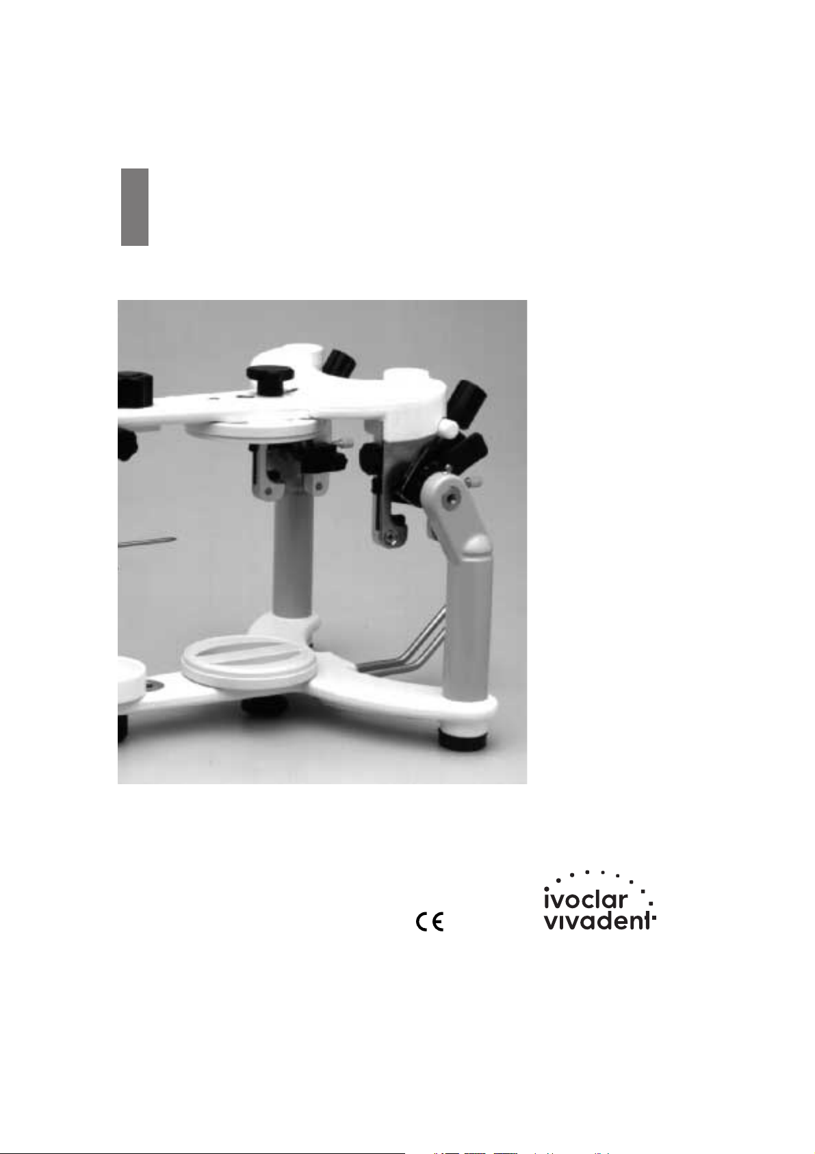
Stratos 200
Ab Fabr. Nr. 10’000
Valid as of Serial No. 10,000
A partir du n°de série
10 000
Dal Nr. di fabbricazione
10.000
A partir del núm. fabric.
10.000
Bedienungsanleitung
Operating Instructions
Mode d’emploi
Istruzioni d’uso
Instrucciones de uso
Page 2

23
Page
Views of the Unit and Parts List 24
– Description of components
– Accessories
– Accessories for average model transfer
– Accessories for personalized model transfer
1 Introduction / Signs and Symbols 28
1.1 Preface
1.2 Signs and symbols
1.3 Information on the Operating Instructions
2 Safety First 29
2.1 Field of application
2.2 Health and safety instructions
3 Product Description 29
3.1 Functional description
3.2 Indication and contraindication
4 Installation and Initial Start-up 30
4.1 Unpacking and checking the contents
4.2 Assembly and initial set-up
4.3 Joint inserts (Protrusion and Bennett inserts)
5 Handling and Operation 31
5.1 Centric position
5.2 Protrusion movement
5.3 Lateral and Bennett movement
5.4 Immediate side-shift movement
5.5 Retrusion movement
6 Model Orientation in the Stratos 200 34
6.1 Average orientation of dentulous and edentulous cases with a rubber band
6.2 Average orientation of dentulous cases with the set-up table
6.3 Average orientation of edentulous cases with the horizontal guide
6.4 Average orientation of dentulous cases with the horizontal guide
6.5 Personalized model transfer with the registration joint holder
6.6 Personalized model transfer with the UTS transferbow
6.7 Personalized setup of anterior guidance
7 Maintenance and Cleaning 39
7.1 Monitoring and maintenance
7.2 Cleaning
8 What If ... 40
8.1 Technical malfunctions
8.2 Repairs
9 Product Specifcations 41
9.1 Delivery form
9.2 Technical data
10 Miscellaneous 42
10.1 Tips on the coordination of articulators
english
Stratos 200
Page 3

24
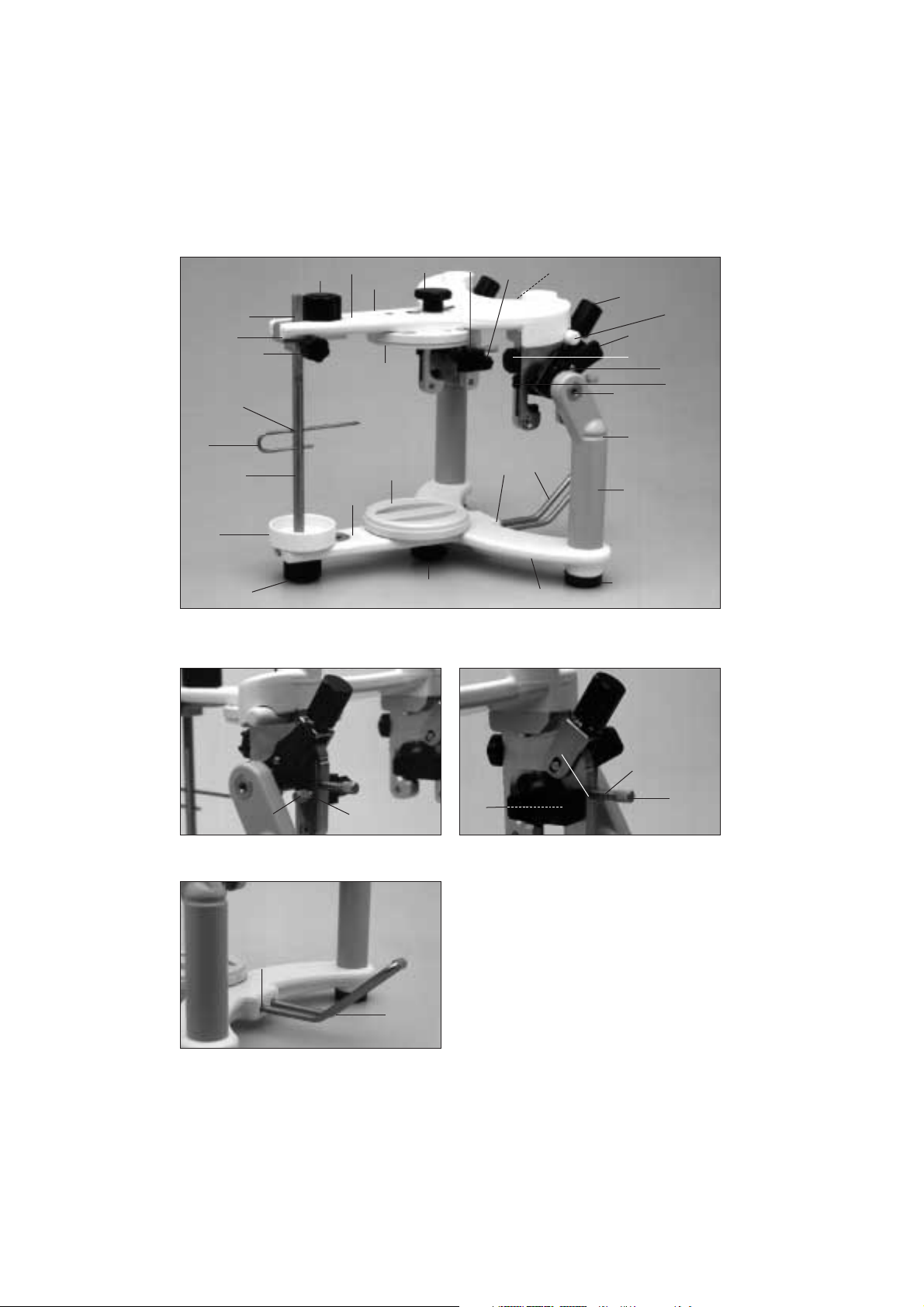
Parts List
Stratos 200
1.1 Adjustable incisal plate
1.2 Incisal guide rod
1.3 Incisal indicator
1.4 Guide rod holder
1.5 Guide rod retaining screw
1.6 Guide rod initial set position (red)
1.7 F-I knurled screw
1.8 Hole for incisal indicator
2.1 G-I knurled screw
2.2 Lower frame
2.3 Upper frame
2.4 Incline supports
2.5 Notch for rubber band
2.6 Non-slip base
3.1 Bennett inserts (exchangeable)
3.2 B-knurled screw
4.1 Centric fixation lock
4.2 Centric rubber band
4.3 Centric rubber band holder
5.1 Protrusion insert (exchangeable)
5.2 P-knurled screw
6.1 Locating hole for transferbow
7.1 Holding device for incline support holder
7.2 Incline support holder
8.0 Articulator number
9.0 Protrusion screw
9.1 Protrusion screw thread
9.2 Protrusion screw spring
10.0 ISS screw
10.1 ISS screw thread
11.0 Opening stop
33 Retentive base block
Page 4
25
1.3
1.8
1.2
1.1
2.1
7.1
7.2
8.0
8.0
8.0
2.2
2.6
2.4
1.7
10.110.0
2.5
6.1
5.1
4.3
2.1
3.1
3.2
2.3
1.7
1.6
5.2
4.2
11.0
4.1
1.4
1.5
9.0
9.1
9.2
33
33
7.2
7.1
3.1
Page 5
26
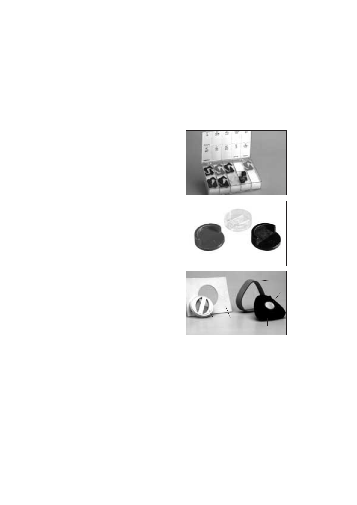
Accessories for the Stratos 200
Protrusion inserts
20 15°
21 20°
22 25°
23 35°
24 40°
25 45°
26 60°
Bennett inserts
27 15°
30 15° incisal plate made of plastic
31 30° incisal plate made of plastic
32 Incisal plate made of MMA-soluble material for
personalized anterior guidance
33 Retentive base block
34 Plaster protection plate
35 Magnetic base block
36 Collar
37 Retention disk
30
32
33
34
36
37
35
31
Page 6
27
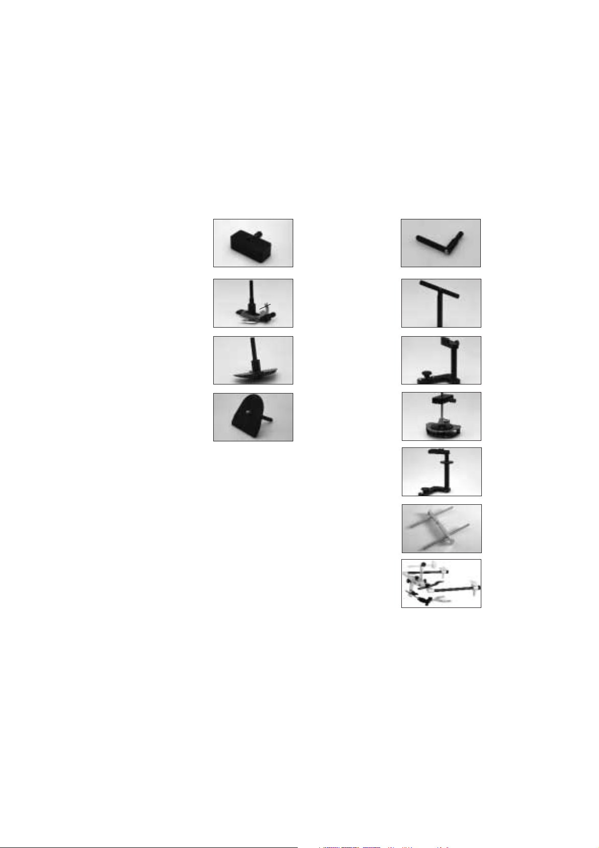
Accessories
for average model transfer
40 Instrument carrier
for horizontal guide
set-up table,
2-D setting-up template
and bite fork support
41 Horizontal guide
41.1 Symphysis fork
42 2-D setting-up
template
43 Set-up table
50 Plane indicator
51 Bite fork support
52 Registration joint
holder (CP)
53 3-D setting-up
template
54 FH registration joint
holder
60 Adjustable support pins
(Type II) for the
UTS transferbow
61 UTS transferbow system
Accessories
for personalized model transfer
41.1
40
50
51
52
53
54
60
61
41
42
43
Page 7

28
1.1 Preface
Dear Customer,
Thank you for having purchased the Stratos 200 articulator. The
Stratos 200 is an advanced technology product that is
characterized by high quality and precision.
The Stratos 200 has been designed according to the latest
industry standards. Inappropriate use may be hazardous. Please
observe the relevant safety instructions and do read the Operating
Instructions carefully.
We wish you much success and satisfaction with the Stratos 200.
1.2 Signs and symbols
The signs and symbols in these Operating Instructions facilitate
the finding of important information. They have the following
meanings:
Risks and dangers
Important information
Contraindication
1.3 Information on the Operating
Instructions
These Instructions apply to the following apparatus:
Stratos 200, as of Serial Number 10,000
Target group:dentists, dental technicians, dental lab
professionals
These Operating Instructions facilitate the correct, safe and
economic use of the Statos 200 articulator.
If you have lost the Operating Instructions, you may order an extra
copy at a nominal fee from your local Ivoclar Vivadent Service
Center.
1. Introduction / Signs and Symbols
Page 8

29
2. Safety First
This chapter is particularly important for staff who work with the
apparatus or who have to carry out maintenance or repair work.
2.1 Field of application
• The Stratos 200 must only be used for the
indications stipulated in Chapter 3. Further instructions
to assure the proper use of the Stratos 200 articulator
are as follows:
• The instructions,regulations and notes in these
Operating Instructions must be observed.
• The unit must be properly maintained
(See chapter 7).
3. Product Description
3.1 Functional description
The Stratos 200 is an adjustable articulator built according to the
Camper’s plane (CP). It is fully coordinated with the Ivoclar
Vivadent Biofunctional Prosthetic System (BPS). Consequently, the
articulator facilitates the easy and effective application of a
prosthetic system that has been successful for many years.
Given the exchangeable protrusion and Bennett joint inserts, the
Stratos 200 is adaptable to future developments.
Additionally,users can choose to work with either a fixed or
swivel axis.
Furthermore, a retrusion movement of 35° as well as an
‘immediate side shift’ are integrated in the Stratos 200.
A newly developed activable centric locking system permits the
articulator to be set to precise, reproducible initial set positions
and faciliates separation and setting of the upper and lower
frames. Even when the centric lock is open,the upper and lower
frames are still connected. Only after removing the centric rubber
bands from their retainers can the two parts be separated.
The locating holes for transferbows,automatic centric return and
a non-slip base are all standard eqiupment. In addition, the
Stratos 200 features a dirt-and-wear-resistant finish.
A wide range of accessories permit the Stratos 200 to meet the
specific needs and requirements of every user.
3.2 Indication and contraindication
Indication
The articulator is suitable for the spatial fixation of models for
dental reconstructions.The basic equipment permits the
simulation of average movements of the human
temporomandibular joint.
Contraindication
No contraindications are known to date provided that
the articulator is used strictly according to the
Operating Instructions.
Page 9

30
4. Installation and Initial Start-up
4.1 Unpacking and checking the contents
Remove the components of the Stratos 200 from their packaging
and check the delivery for completeness.
Stratos 200 basic model
1x Stratos 200
2x Protrusion inserts 30°
2x Protrusion inserts 30° for the fixed axis
2x Bennett inserts 30°
1x Incisal plate 0°
1x Incisal indicator
2x Retentive base blocks
1x Plaster protection plate
1x Incline support holder
If certain parts are missing or damaged, contact your local Ivoclar
Vivadent Customer Service.We recommend keeping the original
packaging for possible future transportation purposes.
4.2 Assembly and initial set-up
Insert the incline support holder (7.2) into the holding device (7.1)
for the incline support holder.If necessary,the incline support
holder can be removed from the
apparatus.
Secure the base block (33) to the articulator by means of the G-I
knurled screw (2.1).
Incline support
The incline support holder enables ergonomic handling of the
articulator.If mounted, it maintains the articulator at approx. a
45° angle.This position permits a superb overview of the model
mounted in the articulator.
4.3 Joint inserts (Protusion and
Bennett inserts)
The joint inserts delivered with the basic model can be exchanged
as necessary (see list of accessories).
Procedure
The Bennett inserts can be removed and exchanged by loosening
the B-knurled screw (3.2).
The B-knurled screw can be completely removed from the Bennett
element.
The corresponding positioning of the P-knurled screw (5.2) permits the exchange of the protrusion inserts (5.1).
3.2
3.1
5.1
5.2
Page 10

31
5.1 Centric position
The Stratos 200 features a precise centric locking system
that can be activated in the following three positions:
5.1.1 Centric fixation lock (4.1) open
This position permits the simulation of jaw movements.
If the centric rubber bands (4.2) are removed, the two
frames can be separated.
5.1.2 Centric fixation lock (4.1) closed
In this position, the two frames of the Stratos 200 can no
longer be separated and the articulator is fixed in the
centric position. The centric fixation can be opened by
applying slight pressure.This greatly faciliates handling
for the user.
5.1.3 Centric fixation (4.1) locked
To lock the centric fixation completely, e.g.if the
articulator has to be transported, or if no movements are
desired, pull the joint axis into the precisely defined, final
position.
Loosen the centric fixation before carrying out
masticatory movements.
5. Handling and Operation
4.1
4.2
4.1
4.1
Page 11

32
5.2 Protrusion movement
5.2.1 Protrusive movements can be simulated if the centric
fixation (4.1) is open, according to the schematic below.
The angle of the protrusion path can adjusted to be more
acute or flat (0-60°) by exchanging the corresponding
protrusion inserts.
5.2.2 Protrusion screw (9.0) for centric shift
The protrusion screw permits each condyle to be
incrementally advanced into a protrusive position (See
diagram).
Important
In this case, the centric fixation must not be
used.
5.3 Lateral and Bennett movement
5.3.1 Lateral and Bennett movements
The lateral movements can be simulated when the centric
fixation (4.1) is open, according to the schematic below.
To effect this movement,press with your thumb
unilaterally on the joint of the corresponding side.
The angle can be adjusted to be more acute or flat (15° or
30°) by exchanging the Bennett inserts.
9.0
Page 12

33
5.4 Immediate side-shift movement
The Bennett inserts (3.1) can be moved to the required
position after loosening the B-knurled screw (3.2). This
permits an immediate side shift. The ISS screw (10.0)
permits the exact fixation of the immediate side-shift
movement.
1 turn = 0.5 mm.
5.5 Retrusion movement
To simulate retrusive movements, the centric fixation lock
(4.1) must be open and the Bennett inserts (3.1) removed.
This allows retrusive movements to be carried out properly.
10.0
3.2
3.1
0–1.5 mm
Page 13

34
6.1 Average model orientation of
dentulous and edentulous cases with
a rubber band
6.1.1 Return articulator to the initial set position
• Check if Bennett inserts
(3.1) are secured in
place.
• Mount centric
rubber bands (4.2).
• Bring centric fixation
lock (4.1) into the upper
position and secure in place.
• Secure incisal guide rod
(1.2) in the initial position (red mark 1.6) of
the guide rod holder.
6.1.2. Incisal indicator (1.3)
Slide the incisal indicator
completely into the incisal
guide rod (1.2).
Insert the
longer part of
the incisal indicator (1.3) into the upper hole
(1.8) of the incisal guide rod (note notch in
the rod).
6.1.3 Next, attach the thin
rubber band to the incline
supports (2.4), notches
(2.5), and under the
longer part of the incisal
indicator (1.3).
6.1.4 Adjust occlusal plane
according to the rubber
band. Adjust mesial
contact area either
between the mandibular
central incisors or on the
wax bite block, according
to the tip of the incisal indicator (1.3).
Example: edentulous case
6.1.5 For best results, mount
mandibular model on
modelling material and
adjust. After that,cast
maxilliary model.
Example: dentulous case
6. Model Orientation in The Stratos 200
1.2
1.8
1.3
1.3
1.3
2.5
2.4
1.6
Page 14

35
6.2 Average orientation of dentulous
cases with the set-up table
6.2.1 Return the articulator to the initial set position
• See page 34 for description
Remove the incisal indicator (1.3).
6.2.2 Mount instrument carrier
to the upper frame (2.3)
and fasten it with the G-I
knurled screw (2.1).
6.2.3 Insert set-up table
completely into the
instrument carrier and
secure it.
6.2.4 Place articulator with the
upper frame (2.3) facing
down on the table.
Orientate the dentulous
mandibular model
according to the mesial
contact area and
symmetry in the molar region. If necessary, use modelling
material to hold it in place.
6.2.5 Apply plaster on model
and base block and close
articulator slowly.
6.2.6 Then, orientate maxillary
model in the usual
manner.
6.3 Average orientation of edentulous
cases with the horizontal guide
6.3.1 Return articulator to the initial set
position
• See page 34 for description
Remove incisal indicator (1.3).
6.3.2 Mark and bisect the
Trigonum retromolare on
the mandibular model.
Bisect the distance
between the upper and
lower mucolabial folds and
set the symphysis fork
(41.1) of the horizontal
plane on the resulting
value.
Using the resulting values,
orientate mandibular
model to the horizontal
guide and hold it in place,
e.g. with a rubber band.
6.3.3 Mount instrument carrier
(40) to the upper frame
(2.3).
Fasten horizontal guide in
place by means of the
knurled screw of the
instrument carrier.
Insert
horizontal
guide
completely
into the instrument carrier.
After that, apply some
plaster on the model and
base block and close articulator slowly.
6.3.4 Next, orientate maxillary model as usual.
4.1
Page 15

6.4 Average orientation of dentulous
cases with the horizontal guide
6.4.1 Return articulator to the initial set
position
• See page 34 for description
Remove the incisal indicator (1.3).
6.4.2 Transfer maxillary mesial
contact area vertically to
the mandibular model.
Mark the tips of both
distobuccal cusps of the
lower second molars. If
these molars are missing,
the first molars may be used instead.
• Put mandibular mesial
contact area behind the
incisal tip of the
symphysis fork.
• Adjust horizontal guide
in such a way that the
rear edges barely cover
the marked cusps of the second molars and establish
symmetry.
• The retromolar pads are used as reference points for
free-end surfaces, similarly to the
Trigonum retromolare in edentulous cases.
Subsequently,attach horizontal guide to the model with
e.g. wax or a rubber band.
6.4.3 Mount instrument carrier
to the upper frame (2.3).
Fasten horizontal guide in
place by means of the
knurled screw of the
instrument carrier.
Insert
horizontal
guide
completely
into the instrument carrier.
After that, apply some
plaster on the model and base block and close articulator
slowly.
6.4.4 Next, orientate maxillary model as usual.
6.5 Personalized model transfer with the
registration joint holder
6.5.1 Return articulator to the initial set position.
• See page 34 for description
Remove incisal indicator (1.2).
6.5.2 Mount the plane
indicator (50) instead of
the incisal guide rod (1.2).
6.5.3 Mount bite fork
support (51) to the lower
frame (2.2) by means of
the instrument carrier (40).
6.5.4 Insert registration joint
holder (52) instead of the
incisal plate (1.1) and
secure it.
6.5.5 Mount UTS registration to
the registration joint
holder and secure bite fork
with the bite fork support.
Example: occlusal
localizing tray
Example: UTS bite fork
(dentulous case)
36
52
Page 16

37
6.5.6. Mount maxillary model to
the bite fork and cast.
Close artic-ulator until the
plane indicator lies on the
registration joint holder.
Example: UTS bite fork
(edentulous case)
FH registration joint
holder (54)
The procedure is the same
as with the CP registration
joint hold-er.The plane
indicator (50) lies on the
relevant support.
6.5.7 Subsequently, orientate mandibular model in the usual
manner.
6.6 Personalized model transfer with the
UTS transferbow
6.6.1 Return articulator to the initial set position.
• See page 34 for description.
Remove incisal indicator (1.2).
6.6.2 Mount the plane indicator (50) instead of the
incisal guide rod (1.2).
6.6.3 Mount bite fork support to the lower frame (2.2) by
means of the instrument carrier.
6.6.4 • Remove glabellar rest
from the transferbow
and insert support pins
(Type II) (60) from
above.
• Insert the UTS into the
locating holes for
transferbows (6.1).
• Using the support pins,
adjust the transferbow
so that it is parallel to
the table top.
• Finally, secure bite fork with the bite fork
support.
6.6.5 Mount maxillary model to
the bite fork and cast.
Close the articulator until
the plane indicator rests in
the notch in the crossbeam of the support pin.
If Type-I support pins are used,close
articulator until the plane indicator touches
the SME indicator of the transferbow.
6.6.6 Then, orientate mandibular model in the usual manner.
50
54
Page 17

38
6.7 Personalized setup of anterior
guidance
For the fabrication of personlized incisal plates,Ivoclar Vivadent
offers a special transparent incisal plate.The plate is made of a
MMA-soluble plastic that bonds with the set-up resin (SR Ivolen).
Anterior guidance plates thus fabricated can always be exactly
repositioned in the Stratos 200.
Procedure
First, mount the transparent 0°
incisal plate.Then, position the
models of the patient for which
the anterior guidance should be
formed in the Stratos 200.
Subsequently,mix appropriate resin and spread it on the incisal
plate. Finally, simulate the registered masticatory movements
(protrusion, retrusion, laterotrusion) with the upper frame of the
Stratos 200. The pattern of movements will thus be scratched into
the resin by the incisal guide rod and recorded after polymerization of the resin.
The forming of the natural facing should be done
from excursion to centric. Otherwise,the resin might
be forced out of the incisal plate. Make sure that no
vertical increase of occlusion occurs.
Page 18

39
This chapter describes the user maintenance and cleaning procedures for the Stratos 200. Only those tasks that can be carried out by
qualified dental lab experts are listed. All other tasks must be performed by qualified service personnel at a certified Ivoclar Vivadent
Service Center.
7. Maintenance and Cleaning
7.1 Monitoring and maintenance
The time for these maintenance procedures depends on the frequency of use and the working habits of the user. For these
reasons, the recommended times are only approximates.
7.2. Cleaning
Protect the Stratos 200 from acids and solvents
(e.g. MMA) to prevent the finish from being damaged.
What
Check centric rubber band for damage and
cracks.
Check if knurled screws are dirty.
Check if joint bolt is sufficiently
lubricated.
Check if incline support holder and holding
device are dirty.
Part
Centric rubber band
Knurled screw
Joint bolt
Holding device for incline support
holder
Frequency
Every six months
Weekly
Monthly or as necessary
Weekly or as necessary
What
Knurled screws contaminated with wax or
plaster
Joint bolt contaminated with dust
Frequency
Weekly or as necessary
Weekly or as necessary
Cleaning agent/Measure
Rinse with warm water
Rinse with warm water
Page 19

40
8. What If ...
8.1 Technical malfunctions
Error
Upper frame exceeds opening stop and
slips backwards.
Articulator cannot be openend when the
centric fixation lock is closed.
Joint bolt is damaged or grooved.
The surface of the articulator is
damaged or etched.
The surface of the apparatus is
scratched or damaged.
Cause/Description
The opening stop is not in place or defective.
Centric fixation has been fixed too
tighly.
The articulator was forcibly opened and
closed with the centric fixation fixed, without the centric fixation being loosened.
Surface was cleaned with acid,
solvent or lye.
Surface was scratched with a sharp instrument.
Action
Replace opening stop or mount it
properly.
Fix centric fixation less tightly.
Loosen centric fixation lock before opening
and closing the articulator.
Do not use acid, solvent or lye to clean the
apparatus.
Do not scratch the surface with a sharp
instrument.
8.2 Repairs
Rapairs may only be carried out by a certified Ivoclar Service Center.Please refer to the addresses mentioned in
Chapter 10. If repairs during the warranty period are not carried out by a certified Ivoclar Vivadent Service
Center,the warranty will expire immediately.
This chapter will help you to recognize malfunctions and take appropriate measures, or,if possible, to perform some repairs.
Page 20

41
9.1. Delivery form
Stratos 200 basic model
1 Stratos 200
2 Protrusion inserts 30°
2 Protrusion inserts for the fixed axis
2 Bennett inserts 30°
1 Incisal plate 0°
1 Incisal indicator
2 Retentive base blocks
1 Plaster protection plate
1 Incline support holder
"Average” Accessories Assortment
• 1 Instrument carrier
• 1 Setup table
• 1 Horizontal guide
• 1 2-D setting-up template
"Personalized” Accessories Assortment
• 1 Complete set of joint inserts
• 2 x 1 Incisal plate 15° and 30°, as well as
1 personalized plate
• 1 Instrument carrier
• 1 Plane indicator
• 1 Registration joint holder
• 1 Bite fork support
Joint inserts
Complete assortment with the following angles:
• Protrusion inserts 15°, 20°, 25°,35°, 40°, 45°,60°; two
inserts of each angle
• Bennett inserts 15°, two inserts
The various angles of the inserts are also available in pairs:
• Protrusion inserts 15°, 20°, 25°,30° open, 30° closed, 35°,
40°, 45°, 60°
• Bennett inserts 15°
Separately available:
• Incisal plate 15° or 30°
• Incisal plate for personalized anterior guidance, package of
5 plates
• Instrument carrier
• Plane indicator
• Horizontal guide
• 2-D setting-up template
• 3-D setting-up template
• Setup table
• Adjustable support pins (Type II)
• Registration joint holder
• Bite fork support
• Magnetic base blocks, package of 2 or 10 blocks
• Retentive base blocks, package of 10 or 50 blocks
• Plaster protection plate, package of 5 plates
• FH registration joint holder
• Incline support holder
• Retention disk for magnetic base block
Colour code
All exchangeable parts with an angle indication are colour-coded.
• white 0°
• red 15 °
• orange 20°
• brown 25°
• black 30°
• grey 35°
• green 40°
• blue 45°
• yellow 60°
• transparent for personalized anterior guidance
The delivery forms may vary from country to
country.
9. Product Specifications
Page 21

42
9.2 Technical data
• Bonwill triangle 108 mm
• Balkwill angle 15°
• Working height 118 mm
• Retrusion path angle 35°
• Protrusion screw 0-4 mm
• ISS: 0-1.5 mm
• Protrusion angle: 30°. Other angles are available as accessories.
• Exchangeable, colour-coded 30° protrusion inserts, for a fixed
or swivel axis
• Exchangeable, colour-coded 30° Bennett inserts. Other angles
are available as accessories
• Exchangeable, colour-coded 0° incisal plates. Other angles are
available as accessories.
• Weight: 950 g
• Colour: apricot/white (RAL 1017, RAL 9016)
10.1 Tips on the coordination of
articulators
The companies below offer split-cast systems for the
Stratos 200.
These systems permit users to coordinate their Stratos 200
articulators. For further information, please contact:
Adesso-split
Baumann Dental GmbH
Senderstrasse 5
D-75417 Mühlacker
Quicksplit
Hans Rossner & Sohn GmbH
Dentaltechnik
Ulmerstrasse 11
D-87700 Memmingen
Please note that the standard accessories can
no longer be used after the apparatus have
been coordinated.
This apparatus has been developed for use in dentistry.Setup and
opera
tion should be carried out strictly according to the Operating
Instructions. Liability cannot be accepted for damages resulting from
misuse or failure to observe the Instructions.The user is soleley
responsible for testing the apparatus for its suitability for any purpose
not explicitly stated in the Instructions. Descriptions and data constitute
no warranty of attributes and are not binding.
10. Miscellaneous
Page 22

Version: 3
Issued: 10/99
Printed in Liechtenstein
© Ivoclar Vivadent AG, FL-9494 Schaan
I558832/0400/1.2/5spr/G
Deutsche Ivoclar Vivadent AG
Bendererstrasse 2
FL-9494 Schaan
Liechtenstein
Tel. +423 / 235 35 35
Fax +423 / 235 33 60
Ivoclar Vivadent Pty. Ltd.
1 – 5 Overseas Drive
P.O. Box 367
Noble Park,Vic. 3174
Australia
Tel. 03 / 97959599
Ivoclar Vivadent Ltda.
Rua Maestro João Gomes de
Araújo 50
Salas 92/94
Sao Paulo,CEP 02332-020
Brasil
Tel. +55 11 69 59 89 77 /
69 71 17 50
Ivoclar Vivadent Marketing Ltd.
Calle 134 No. 13-83, Of. 520
Santafé de Bogotá
Colombia
Tel. +57 1 627 33 99
Ivoclar Vivadent S.A.
B.P. 118
F-74410 Saint-Jorioz
France
Tel. 04.50.88.64.00
Ivoclar Vivadent GmbH
Postfach 1152
D-73471 Ellwangen
Germany
Tel. 07961 / 889-0
Ivoclar Vivadent UK Limited
Meridian South
Leicester
LE3 2WY
Great Britain
Tel. 116 / 265 40 55
Ivoclar Vivadent GmbH
Via dell’Industria 16
I-39025 Naturno (BZ)
Italy
Tel. 0473 / 67 01 11
Ivoclar Vivadent S.A. de C.V.
Av. Mazatlán No. 61, Piso 2
Col. Condesa
06170 México, D.F.
Mexico
Tel. (5) 553-0038
Ivoclar Vivadent Ltd
12 Omega St, Albany
PO Box 5243 Wellesley St
Auckland, New Zealand
Tel 09 / 914-9999
Ivoclar Vivadent Polska Sp. z.o.o.
PL-01-501 Warszawa
ul. Jana Pawla II 78
Poland
Tel. 635 54 96 / 635 54 97
Ivoclar Vivadent S.A.
c/Valderribas 82
E-28007 Madrid
Spain
Tel. 91 / 513 10 08
Ivoclar Vivadent Nordic AB
Dalvägen 16
S-169 56 Solna
Sweden
Tel. 08 / 514 93 930
Fax 08 / 514 93 940
Ivoclar Vivadent, Inc.
175 Pineview Drive
Amherst, N.Y. 14228
USA
Tel. (800) 533-6825
Ivoclar Vivadent, Inc.
23 Hannover Drive
St. Catharines, Ont. L2W 1A3
Canada
Tel. (800) 263-8182
Ivoclar Vivadent – worldwide
 Loading...