

Page 1
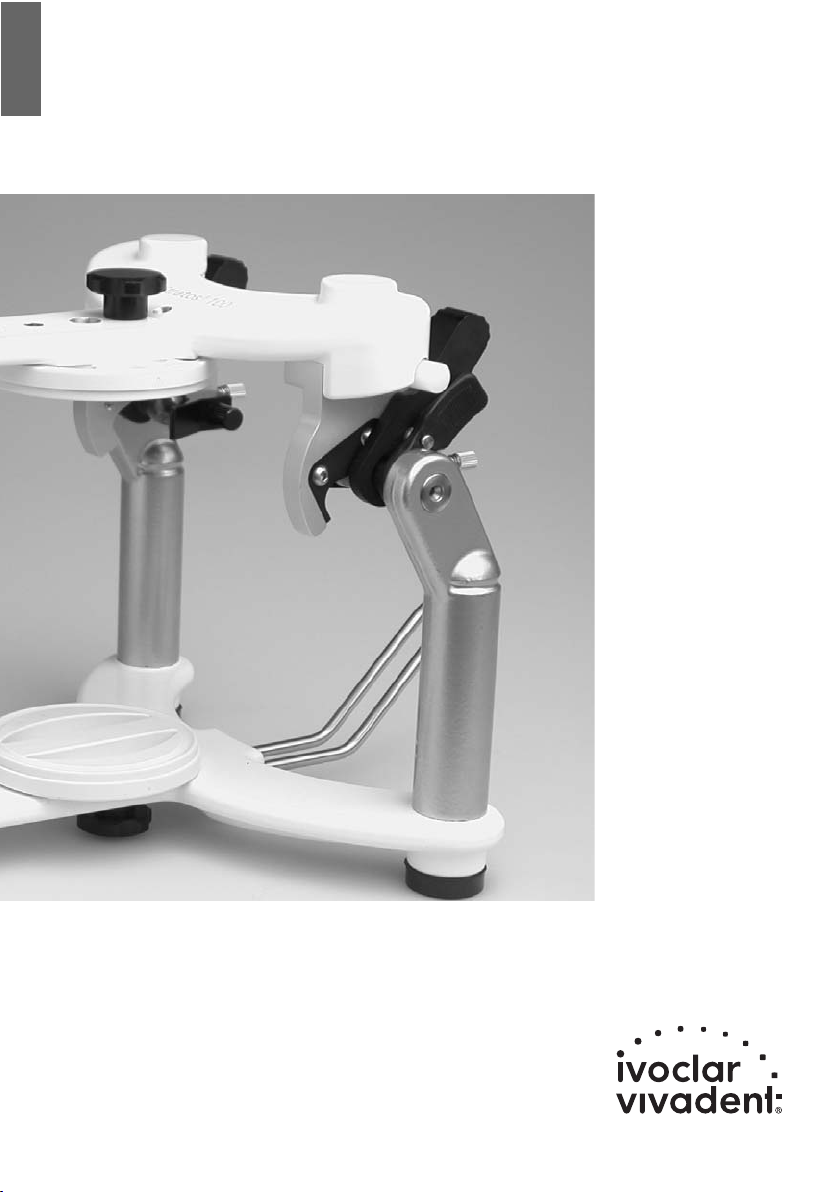
Stratos
®
100
Operating Instructions
Page 3
Bedienungsanleitung
Seite 21
Mode d’emploi
Page 39
Istruzioni d’uso
Pagina 57
Instrucciones de uso
Pagina 75
Page 2

2
Page 3

3
Stratos
®
100
Page
Views of the Unit and Parts List 4
– Description of components 4
– Accessories 6
– Accessories for average model transfer 7
– Accessories for personalized model transfer 7
1 Introduction / Signs and Symbols 8
1.1 Preface 8
1.2 Signs and symbols 8
1.3 Information on the Operating Instructions 8
2 Safety First 9
2.1 Field of application 9
2.2 Health and safety instructions 9
3 Product Description 9
3.1 Functional description 9
3.2 Indication, contraindication 9
4 Installation and Initial Start-up 10
4.1 Unpacking and checking the contents 10
4.2 Assembly and initial set-up 10
5 Handling and Operation 10
5.1 Centric position 10
5.2 Lateral and Bennett movement 11
5.3 Protrusion 11
5.4 Retrusion 12
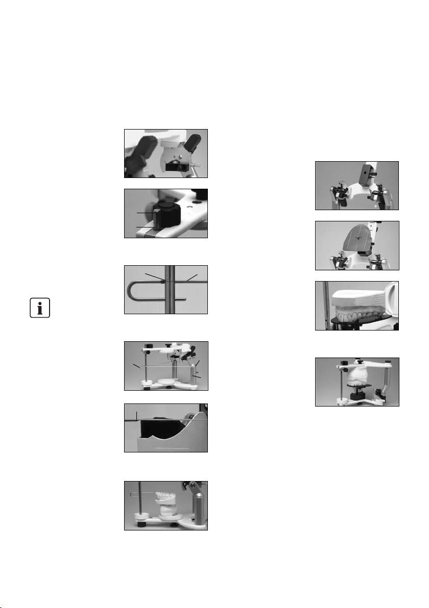
6 Model Orientation in the Stratos 100 13
6.1 Average orientation of dentulous and edentulous cases with a rubber band 13
6.2 Average orientation of dentulous cases with the set-up table 13
6.3 Average orientation of edentulous cases with the horizontal guide 14
6.4 Average orientation of dentulous cases with the horizontal guide 14
6.5 Personalized model transfer with the registration joint holder 15
6.6 Personalized model transfer with the UTS transferbow 16
6.7 Personalized setup of anterior guidance 16
7 Maintenance and Cleaning 17
7.1 Monitoring and maintenance 17
7.2 Cleaning 17
8 What If ... 18
8.1 Technical malfunctions 18
8.2 Repairs 18
9 Product Specifications 19
9.1 Delivery form 19
9.2 Technical data 19
10 Miscellaneous 20
10.1 Tips on the coordination of articulators 20
english
Page 4

4
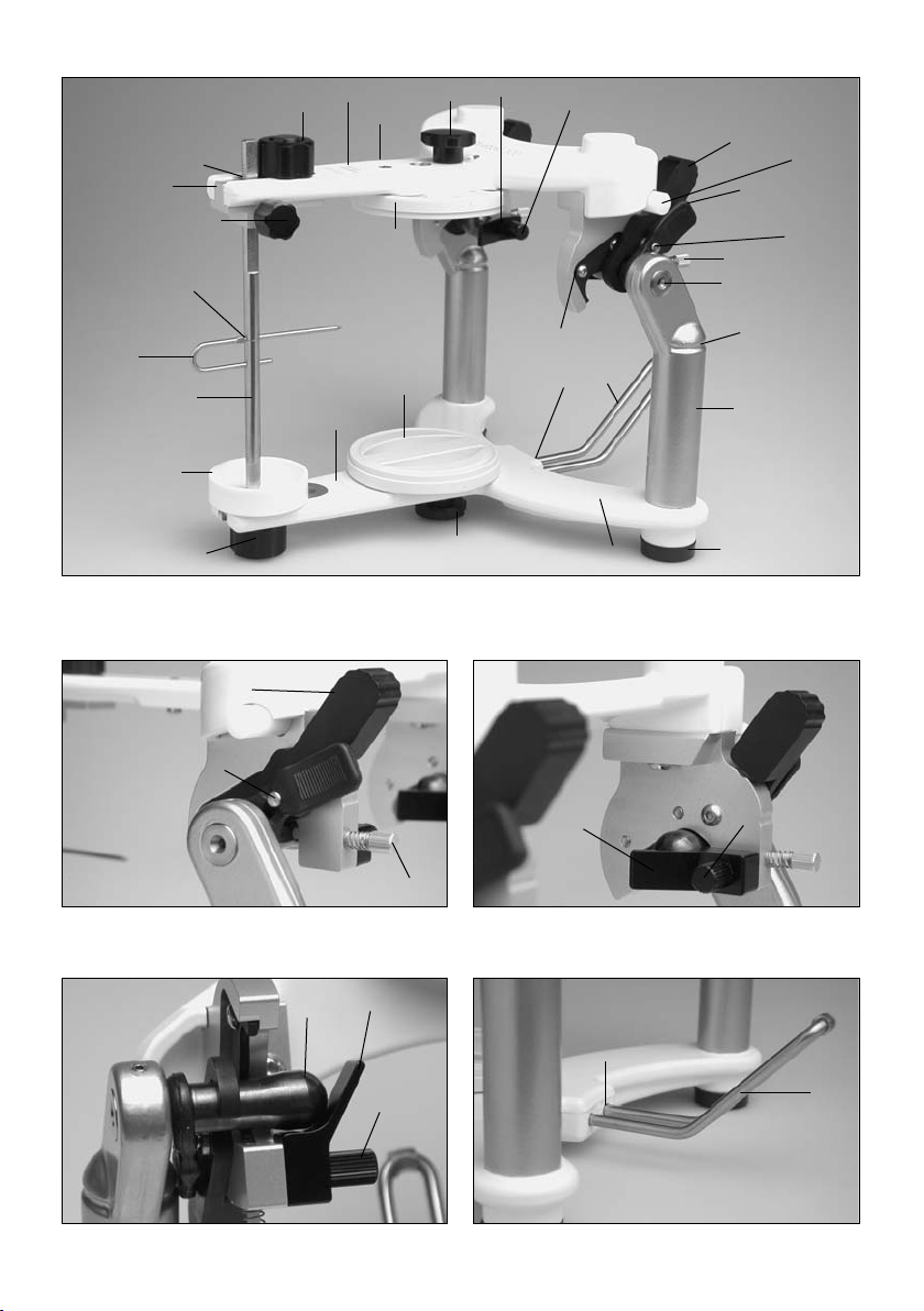
Parts List
Stratos®100
1.1 Incisal plate
1.2 Incisal guide rod
1.3 Incisal indicator
1.4 Guide rod holder
1.5 Guide rod retaining screw
1.6 Guide rod initial set position (red)
1.7 FI knurled screw
1.8 Hole for incisal indicator
2.1 GI knurled screw
2.2 Lower frame
2.3 Upper frame
2.4 Incline supports
2.5 Notch for rubber band
2.6 Non-slip base
2.7 Joint bolt
3.1 Bennett inserts
3.2 B knurled screw
4.1 Centric fixation lock (activable centric locking system)
4.2 Centric rubber band
4.3 Centric rubber band holder
5.0 Protrusion insert (fix)
6.0 Locating hole for transferbow
7.1 Holding device for incline support holder
7.2 Incline support holder
8.0 Articulator number
9.0 Opening stop
10.0 Protrusion screw with spring
33 Retentive base block
Page 5

5
1.3
1.8
1.2
1.1
2.1
7.1
7.2
8.0
8.0
2.2
2.6
2.4
1.7
10.0
4.1
4.3
2.5
6.0
10.0
5.0
4.3
2.1
3.1
3.2
2.3
1.7
1.6
4.2
9.0
4.1
1.4
1.5
33
33
7.2
7.1
3.1
3.2
3.1
3.2
2.7
Page 6

6
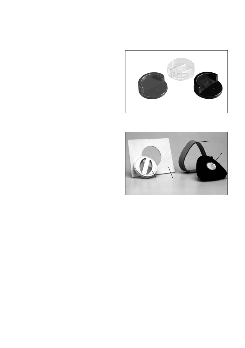
Accessories for the Stratos
®
100
30 15° incisal plate made of plastic
31 30° incisal plate made of plastic
32 Incisal plate made of MMA-soluble material for
personalized anterior guidance
33 Retentive base block
34 Plaster protection plate
35 Magnetic base block
36 Collar
37 Retention disk
30
32
33
34
36
37
35
31
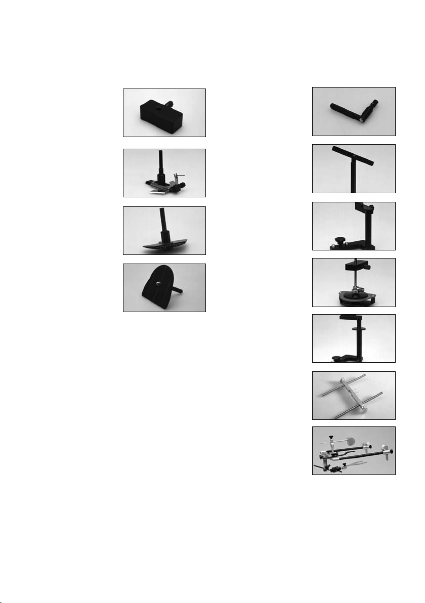
Page 7

40 Instrument carrier for
horizontal guide, set-up
table, 2-D setting up
template and bite fork
support
41 Horizontal guide
41.1 Symphysis fork
42 2-D setting up template
43 Set-up table
7
Accessories for
average model transfer
50 Plane indicator
51 Bite fork support
52 Registration joint holder
(CP)
53 3-D setting up template
54 FH registration joint
holder
60 Adjustable support pins
(Type 2) for the UTS
transferbow
61 UTS transferbow system
Accessories for
personalized model transfer
41.1
40
50
51
52
53
54
60
61
41
42
43
Page 8

8
1.1 Preface
Dear Customer
Thank you for having purchased the Stratos 100 articulator.
The Stratos 100 is an advanced technology product that is
characterized by high quality and precision.
The Stratos 100 has been designed according to the latest
industry standards. Inappropriate use may be hazardous. Please
observe the relevant safety instructions and do read the Operating
Instructions carefully.
We wish you much success and satisfaction with the Stratos 100.
1.2 Signs and symbols
The signs and symbols in these Operating Instructions facilitate
the finding of important information. They have the following
meanings:
Risks and dangers
Important information
Contraindication
1.3 Information on the Operating Instructions
Target group:dentists, dental technicians,dental lab professionals
These Operating Instructions facilitate the correct, safe and
economic use of the Stratos 100 articulator.
If you have lost the Operating Instructions, you may order an
extra copy at a nominal fee from your local Ivoclar Vivadent
Service Center.
1. Introduction / Signs and Symbols
Page 9
9
2. Safety First
This chapter is particularly important for staff who work with the
apparatus or who have to carry out maintenance or repair work.
2.1 Field of application
The Stratos 100 must only be used for the indications stipulated in
Chapter 3. Further instructions to assure the proper use of the
Stratos 100 articulator are as follows:
– The instructions, regulations and notes in these Operating
Instructions must be observed.
– The unit must be properly maintained (see Chapter 7).
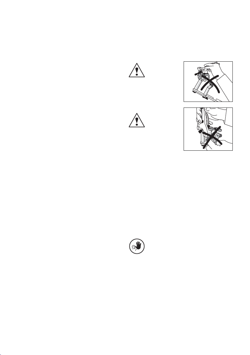
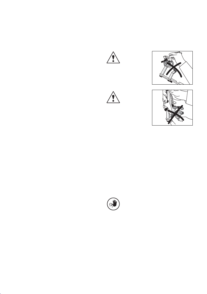
2.2 Health and safety instructions
If the centric rubber
bands are removed
from their retainers
and the centric fixation
lock is open, the upper and lower
frames may be accidentally
separated.
Risk of crushing
between centric
locking catch and
incline support.
3. Product Description
3.1 Functional description
The Stratos 100 is an average-value articulator built according to
the Camper's plane (CP). It is fully coordinated with the Ivoclar
Vivadent Biofunctional Prosthetic System (BPS). Consequently, the
articulator facilitates the easy and effective application of a
prosthetic system that has been successful for many years.
The device is equipped with a fix protrusion path angle of 30°.
The Bennett angle is 15° and 30°.
Furthermore, a retrusive movement of 35° as well as an
“immediate side shift” are integrated in the Stratos 100.
A newly developed activable centric locking system permits the
articulator to be set to a precise, reproducible initial set position
and facilitates separation and connection of the upper and lower
frames. Even when the centric lock is open,the upper and lower
frames are still connected. Only after removing the centric rubber
bands from their retainers can the two parts be separated.
The locating holes for transferbows,automatic centric return and
a non-slip base are all standard equipment. In addition, the
Stratos 100 features a dirt-and-wear-resistant finish.
A wide range of accessories permits the Stratos 100 to meet the
specific needs and requirements of every user.
3.2 Indication and contraindication
Indication
The articulator is suitable for the spatial fixation of models for
lab-fabricated reconstructions.The basic equipment permits
simulation of average movement patterns of the human
temporomandibular joint.
Contraindication
No contraindications are known to date provided that
the articulator is used strictly according to the
Operating Instructions.
Page 10

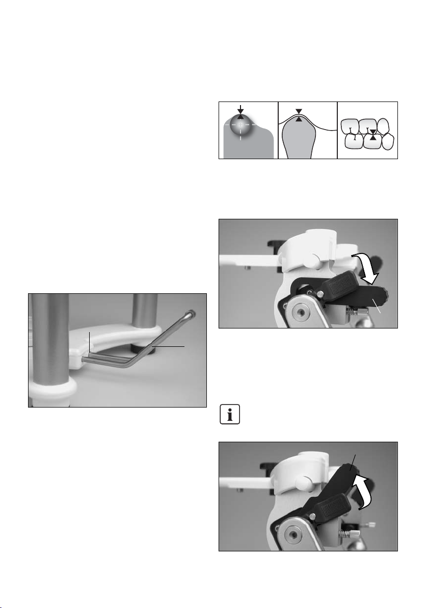
5.1 Centric position
The Stratos 100 features a precise centric locking system that can
be activated in the following positions:
5.1.1 Centric fixation (4.1) open
This position permits the simulation of jaw movements.
5.1.2 Centric fixation lock (4.1) closed
In this position, the two frames of the Stratos 100 can no longer
be separated and the articulator is fixed in the centric position.
The centric fixation can be opened by applying slight pressure.
This greatly facilitates handling for the user.
Loosen the centric fixation before carrying out
masticatory movements.
10
4.1
5. Handling and Operation 4. Installation and Initial Start-up
4.1 Unpacking and checking the contents
Remove the components of the Stratos 100 from their packaging
and check the delivery for completeness.
Stratos 100 basic model:
1 x Stratos 100
1 x Incisal plate 0°
1 x Incisal indicator
2 x Retentive base blocks
1 x Plaster protection plate
1 x Incline support holder
If certain parts are missing or damaged, contact your local Ivoclar
Vivadent Customer Service.We recommend keeping the original
packaging for possible future transportation purposes.
4.2 Assembly and initial set-up
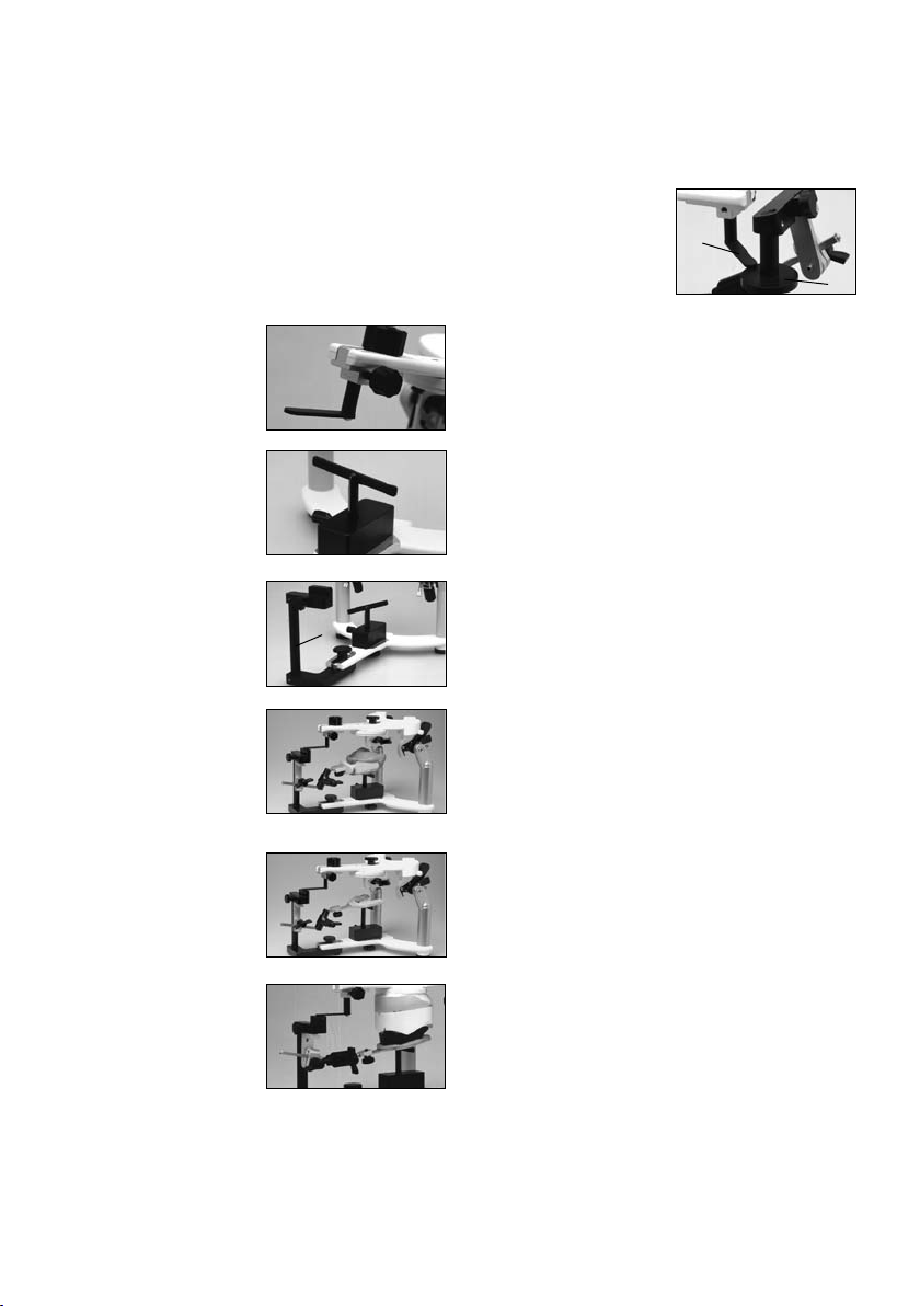
Incline support holder
The incline support holder enables ergonomic handling of the
articulator.If mounted,it maintains the articulator at approx.a
45° angle.This position permits a superb overview of the model
mounted in the articulator.
Insert the incline support holder (7.2) into the holding device (7.1)
for the incline support holder.If necessary, the incline support
holder can be removed from the apparatus.
Secure the base block (33) to the articulator by means of the
GI knurled screw (2.1).
Alternatively,the protrusion screw (5.2) including spring may be
mounted.
4.1
7.2
7.1
Page 11
If the centric rubber bands (4.2) are removed, the two frames can
be separated.
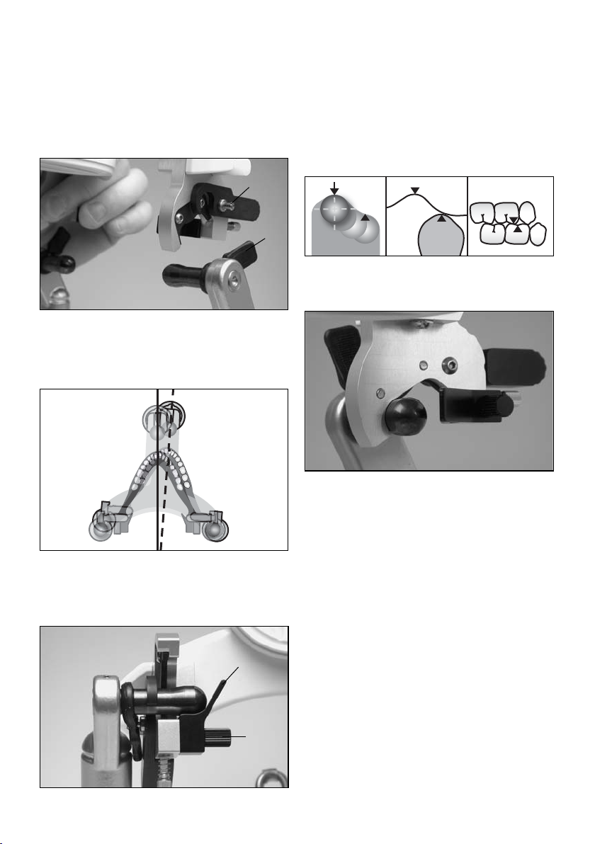
5.2 Lateral and Bennett movement
5.2.1 Lateral and Bennett movement
The lateral movements can be simulated when the centric fixation
(4.1) is open, according to the schematic below.
To perform this movement,press with your thumb unilaterally on
the joint of the corresponding side.
By loosening the B knurled screw (3.2) the Bennett insert (3.1)
can be removed.
5.3 Protrusion
5.3.1 Protrusive movements can be simulated if the centric
fixation (4.1) is open, according to the schematic below.
To effect this movement,press with your thumb bilaterally on the
joint of the corresponding side.
11
3.1
3.2
4.2
4.3
Page 12
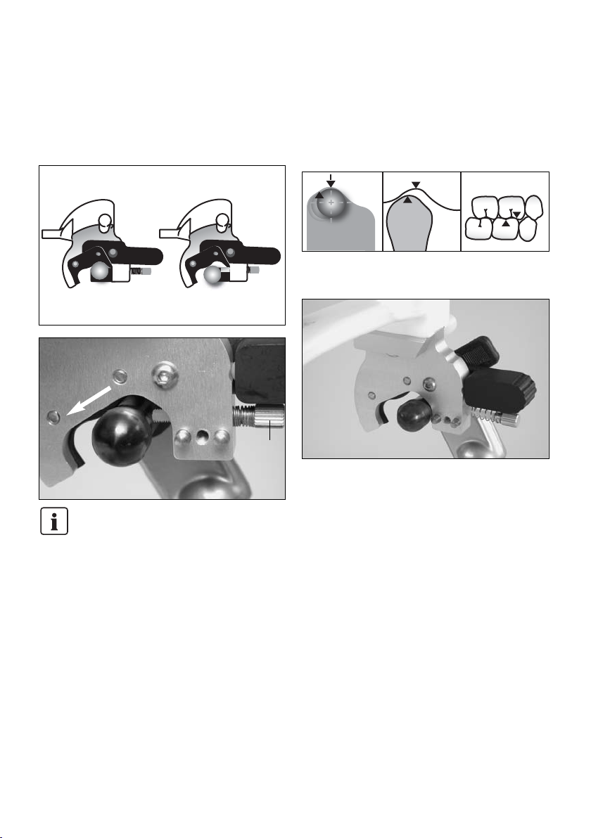
5.3.2 Protrusion screw (10.0) for centric shift
The protrusion screw permits each condyle to be incrementally
advanced into a protrusive position.
Important:
In this case, the centric fixation cannot be used.
5.4 Retrusion
To simulate retrusive movements, the centric fixation lock (4.1)
must be open and the Bennett inserts (3.1) removed.
This allows retrusive movements to be carried out properly.
12
10.0
Page 13
13
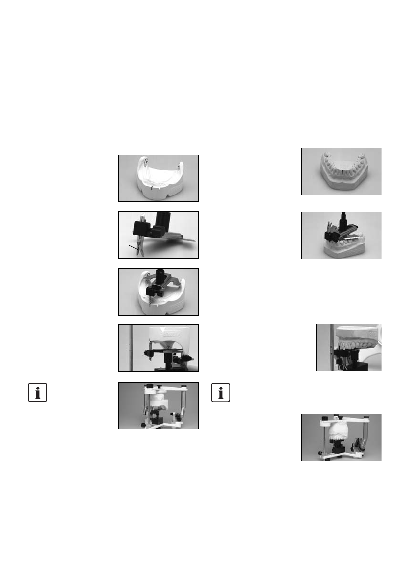
6.1 Average model orientation of dentulous
and edentulous cases with a rubber band
6.1.1 Return articulator to the initial set position
– Check if Bennett inserts (3.1)
are secured in place.
– Mount centric rubber bands
(4.2).
– Bring centric fixation lock
(4.1) into the upper position
and secure in place.
– Secure incisal guide rod (1.2)
in the initial position (red
mark 1.6) in the guide rod
holder
6.1.2 Incisal indicator (1.3)
Slide the incisal indicator
completely into the incisal guide
rod (1.2).
Insert the longer part of
the incisal indicator
(1.3) into the upper hole
(1.8) of the incisal guide rod (note notch in the rod).
6.1.3 Next, attach the thin rub-
ber band to the incline supports
(2.4), notches (2.5), and under the
longer part of the incisal indicator
(1.3).
6.1.4 Adjust occlusal plane
according to the rubber band.
Adjust mesial contact area either
between the mandibular central
incisors or on the wax bite block,
according to the tip of the incisal
indicator (1.3).
Example: edentulous case
6.1.5 For best results,mount
mandibular model on modelling
material and adjust. After that,
cast maxillary model.
Example: dentulous case
6.2 Average orientation of dentulous cases with
the set-up table
6.2.1 Return the articulator to the initial set position
– See 6.1.1 for description
Remove the incisal indicator (1.3).
6.2.2 Mount instrument carrier
to the upper frame (2.3) and
fasten it with the GI knurled
screw (2.1).
6.2.3 Insert set-up table
completely into the instrument
carrier and secure it.
6.2.4 Place articulator with the
upper frame (2.3) facing down on
the table. Orientate the dentulous
mandibular model according to
the mesial contact area and
symmetry in the molar region. If
necessary,use modelling material
to hold it in place.
6.2.5 Apply plaster on model
and base block and close
articulator slowly.
6.2.6 Then, orientate maxillary model in the usual manner.
6. Model Orientation in the Stratos 100
1.2
1.8
1.3
1.3
1.6
1.3
2.5
2.4
Page 14
14
6.3 Average orientation of edentulous cases with
the horizontal guide
6.3.1 Return articulator to the initial set position
– See 6.1.1 for description
Remove incisal indicator (1.3).
6.3.2 Mark and bisect the
Trigonom retromolare on the
mandibular model.
Bisect the distance between the
upper and lower mucolabial folds
and set the symphysis fork (4.1)
of the horizontal plane on the
resulting value.
Using the resulting values,
orientate the mandibular model
to the horizontal guide and hold
it in place, e.g. with a rubber
band.
6.3.3 Mount instrument carrier
to the upper frame (2.3)
Fasten horizontal guide in place
by means of the knurled screw of
the instrument carrier.
Insert horizontal guide
completely into the
instrument carrier.After
that, apply some plaster
on the model and base
block and close articulator slowly.
6.3.4 Next, orientate maxillary model as usual.
6.4 Average orientation of dentulous cases with
the horizontal guide
6.4.1 Return articulator to the initial set position
– See 6.1.1 for description
Remove incisal indicator (1.3).
6.4.2 Transfer maxillary mesial
contact area vertically to the
mandibular model. Mark the tips
of both distobuccal cusps of the
lower second molars. If these
molars are missing, the first
molars may be used instead.
– Put mandibular mesial con-
tact area behind the incisal
tip of the symphysis fork.
– Adjust horizontal guide in
such a way that the rear
edges barely cover the marked cusps of the second molars and align symmetry.
– The retromolar pads are used as reference points for free-end
surfaces, similarly to the Trigonum retromolare in edentulous
cases.
Subsequently,attach horizontal guide to the model with e.g. wax
or a rubber band.
6.4.3 Mount instrument carrier to the
upper frame (2.3).
Fasten horizontal guide in place by
means of the knurled screw of the
instrument carrier.
Insert horizontal guide
completely into the
instrument carrier.
After that, apply some plaster on
the model and base block and
close articulator slowly.
6.4.4 Next, orientate maxillary model as usual.
4.1
Page 15
15
6.5 Personalized model transfer with the
registration joint holder
6.5.1 Return articulator to the initial set position
– See 6.1.1 for description
Remove incisal indicator (1.2).
6.5.2 Mount the plane indicator
(50) instead of the incisal guide
rod (1.2).
6.5.3 Mount bite fork support
(51) to the lower frame (2.2) by
means of the instrument carrier
(40).
6.5.4 Insert registration joint
holder (52) instead of the incisal
plate (1.1) and secure it.
6.5.5 6.5.5 Mount UTS registra-
tion to the registration joint
holder and secure bite fork with
the bite fork support.
Example: Centric Tray
Example: UTS bite fork (dentulous
case)
6.5.6 Mount maxillary model to
the bite fork and cast. Close
articulator until the plane
indicator lies on the registration
joint holder.
Example: UTS bite fork
(edentulous case)
FH registration joint holder
(54)
The procedure is the same as with
the CP registration joint holder.
The plane indicator (50) lies on
the relevant support of the FH
registration joint holder (54).
6.5.7 Subsequently,orientate mandibular model in the usual
manner.
52
50
54
Page 16
16
6.6 Personalized model transfer with the UTS
transferbow
6.6.1 Return articulator to the initial set position.
– See 6.1.1 for description
Remove incisal guide rod (1.2).
6.6.2 Mount the plane indicator (50) instead of the incisal guide
rod (1.2).
6.6.3 Mount bite fork support to the lower frame (2.2) by means
of the instrument carrier.
6.6.4
– Remove nose rest from the
transferbow and insert
support pins (Type II) (60)
from above.
– Insert the UTS into the
locating holes for transferbows (6.1).
– Using the support pins, adjust
the transferbow so that it is
parallel to the table top.
– Finally, secure bite fork with
the bite fork support.
6.6.5 Mount maxillary model to
the bite fork and cast. Close the
articulator until the plane
indicator rests in the notch in the
cross-beam of the support pin.
If Type-I support pins are used,close articulator until the
plane indicator touches the SME indicator of the transferbow.
6.6.6 Then, orientate mandibular model in the usual manner.
6.7 Personalized setup of anterior guidance
For the fabrication of personalized incisal plates,Ivoclar Vivadent
offers a special transparent incisal plate.The plate is made of a
MMA-soluble plastic that bonds with the set-up resin (SR Ivolen).
Anterior guidance plates thus fabricated can always be exactly
repositioned in the Stratos 100.
Procedure
First, mount the transparent 0°
incisal plate.Then, position the
models of the patient for which
the anterior guidance should be
formed in the Stratos 100. Subsequently,mix appropriate resin and
spread it on the incisal plate.
Finally, simulate the registered masticatory movements
(protrusion, retrusion, laterotrusion) with the upper frame of the
Stratos 100. The movement patterns will thus be scratched
into the resin by the incisal guide rod and recorded after polymerization of the resin.
The forming of the natural facets should be done from
excursion to centric. Otherwise,the resin might be forced
out of the incisal plate. Make sure that no vertical
increase of occlusion occurs.
Page 17

17
This chapter describes the user maintenance and cleaning procedure for the Stratos 100. Only those tasks that can be carried out by
qualified dental lab experts are listed. All other tasks must be performed by qualified service personnel at a certified Ivoclar Vivadent
Service Center.
7. Maintenance and Cleaning
7.1 Monitoring and maintenance
The time for these maintenance procedures depends on the frequency of use and the working habits of the user. For these reasons, the
recommended times are only approximates.
7.2. Cleaning
Protect the Stratos 100 from acids and
solvents (e.g. MMA) to prevent the
finish from being damaged.
What
Check centric rubber band for damage and
cracks and replace, if necessary.
Check if knurled screws are dirty.
Check if joint bolt is sufficiently lubricated.
Check if incline support holder and holding
device are dirty.
Part
Centric rubber band
Knurled screw
Joint bolt
Holding device for incline support holder
Frequency
Monthly or as necessary
Weekly
Monthly or as necessary
Weekly or as necessary
What
Knurled screws contaminated with wax or
plaster
Joint bolt contaminated with dust
Frequency
Weekly or as necessary
Weekly or as necessary
Cleaning agent/Measure
Rinse with warm water
Rinse with warm water
Page 18

18
8. What If ...?
8.1 Technical malfunctions
Error
Upper frame exceeds opening stop and
slips backwards.
Articulator cannot be opened when the
centric fixation lock is closed.
Joint bolt is damaged or grooved.
The surface of the articulator is damaged
or etched.
The surface of the apparatus is scratched
or damaged.
Cause/Description
The opening stop is not in place or
defective.
Centric fixation has been fixed too tightly.
The articulator was forcibly opened and
closed without the centric fixation being
loosened.
Surface was cleaned with acid, solvent or
lye.
Surface was scratched with a sharp
instrument.
Action
Replace opening stop or mount it properly.
Fix centric fixation less tightly.
Loosen centric fixation lock before opening
and closing the articulator.
Do not use acid, solvents or lye to clean
the apparatus.
Do not scratch the surface with a sharp
instrument.
8.2 Repairs
Repairs may only be carried out by a certified Ivoclar Vivadent Service Center.Please refer to the addresses mentioned in
Chapter 10. If repairs during the warranty period are not carried out by a certified Ivoclar Vivadent Service Center, the warranty
will expire immediately.
This chapter will help you to recognize malfunctions and take appropriate measures or, if possible, to perform some repairs.
Page 19

19
9.1 Delivery forms
Stratos 100 basic model
1 Stratos 100
1 Incisal plate 0°
1 Incisal indicator
2 Retentive base blocks
1 Plaster protection plate
1 Incline support holder
2 Protrusion screws with spring
"Average” Accessories Assortment
– 1 Instrument carrier
– 1 Setup table
– 1 Horizontal guide
– 1 2-D setting up template
“Personalized” Accessories Assortment
– 1 Incisal plate 15° and 30° each, as well as
1 personalized plate
– 1 Instrument carrier
– 1 Plane indicator
– 1 CE registration joint holder
– 1 Bite fork support
Separately available:
– Incisal plate 15° or 30°
- Incisal plate for personalized anterior guidance, package of 5
plates
– Instrument carrier
– Plane indicator
– Horizontal guide
– 2-D setting up template
– 3-D setting up template
– Set-up table
– Adjustable support pins (Type II)
– CE registration joint holder
– Bite fork support
– Magnetic base blocks, package of 2 or 10 blocks
– Retentive base blocks, package of 10 or 50 blocks
– Plaster protection plate, package of 5 plates
– FH registration joint holder
– Incline support holder
– Retention disk for magnetic base block
Colour code (incisal plate)
All exchangeable parts with an angle indication are colour-coded:
– white 0°
– red 15°
– black 30°
– transparent for personalized anterior guidance
The delivery forms may vary from country to
country.
9.2 Technical data
– Bonnwill triangle 108 mm
– Balkwill angle 15°
– Working height 118 mm
– Retrusion path angle 35°
– Protrusion angle: 30°
– Bennett angle 30°/15°
– Exchangeable, colour-coded 0° incisal plate.Other angles are
available as accessories.
– Weight: 950 g
– Colour: white (RAL 9016), incline support: silver
9. Product Specifications
Page 20

20
10.1 Tips on the coordination of articulators
The companies below offer split-cast systems for the Stratos 100.
These systems permit users to coordinate their Stratos 100
articulators. For further information please contact:
Adesso-split
Baumann Dental GmbH
Frankenstr. 25
D-75210 Keltern-Ellmendingen
Quicksplit
Hans Rossner & Sohn GmbH
Dentaltechnik
Ulmerstrasse 11
D-87700 Memmingen
Please note that the standard accessories can no longer
be used after the apparatus have been coordinated.
This apparatus has been developed for use in dentistry.Setup and operation
should be carried out strictly according to the Operating Instructions. Liability
cannot be accepted for damages resulting from misuse or failure to observe the
Instructions.The user is solely responsible for testing the apparatus for its
suitability for any purpose not explicitly stated in the Instructions. Descriptions
and data constitute no warranty of attributes and are not binding.
10. Miscellaneous
Page 21

21
deutsch
Stratos
®
100
Seite
Geräteübersicht, Teileverzeichnis 22
– Bezeichnung der Teile 22
– Zubehör 24
– Zubehör für die mittelwertige Modellübertragung 25
– Zubehör für die individuelle Modellübertragung 25
1 Einleitung und Zeichenerklärung 26
1.1 Vorwort 26
1.2 Zeichenerklärung 26
1.3 Angaben zur Bedienungsanleitung 26
2 Sicherheit geht vor 27
2.1 Bestimmungsgemässe Verwendung 27
2.2 Sicherheits- und Gefahrenhinweise 27
3 Produktbeschreibung 27
3.1 Aufbau des Gerätes, Funktionsbeschreibung 27
3.2 Indikation, Kontraindikation 27
4 Installation und erste Inbetriebnahme 28
4.1 Auspacken und Lieferumfang prüfen 28
4.2 Zusammenbau und erste Inbetriebnahme 28
5 Handhabung, Bedienung 28
5.1 Zentrikposition 28
5.2 Lateral- und Bennettbewegung 29
5.3 Protrusionsbewegung 29
5.4 Retrusionsbewegung 30
6 Praktische Anwendung der Modellorientierung 31
6.1 Bezahnter oder unbezahnter Fall mit Gummiband (mittelwertig) 31
6.2 Bezahnter Fall mit dem Einrichttisch (mittelwertig) 31
6.3 Unbezahnter Fall mit Fundamentwaage (mittelwertig) 32
6.4 Bezahnter Fall mit Fundamentwaage (mittelwertig) 32
6.5 Modellübertragung mit dem Registriergelenkträger (individuell) 33
6.6 Modellübertragung mit dem UTS-Transferbogen (individuell) 34
6.7 Individuell aufgebauter Frontzahnführungsteller 34
7 Unterhalt, Reinigung, Diagnose 35
7.1 Kontroll- und Unterhaltsarbeiten 35
7.2 Reinigungsarbeiten 35
8 Was ist, wenn ... 36
8.1 Technische Störungen 36
8.2 Reparaturarbeiten 36
9 Produktspezifikationen 37
9.1 Lieferform 37
9.2 Technische Daten 37
10 Sonstiges 38
10.1 Tipps zur Artikulator-Gleichschaltung 38
Page 22

22
Teileverzeichnis
Stratos®100
1.1 Inzisalteller
1.2 Inzisalstift
1.3 Inzisalpunktzeiger
1.4 Inzisalstifthalter
1.5 Inzisalstift-Rändelschraube
1.6 Inzisalstift Nullposition (rot)
1.7 FI-Rändelschraube
1.8 Bohrung für Inszialpunktzeiger
2.1 GI-Rändelschraube
2.2 UK-Grundteil
2.3 OK-Grundteil
2.4 Säulen
2.5 Kerbe für Gummiband
2.6 Gummifüsse
2.7 Gelenkbolzen
3.1 Bennett-Einsätze
3.2 B-Rändelschraube
4.1 Zentrikfixierung (aktivierbarer Schnellverschluss)
4.2 Zentrikgummi
4.3 Halterung für Zentrikgummi
5.0 Protrusions-Einsatz (fix)
6.0 Transferbogenanschluss
7.1 Halterung für Stützfuss
7.2 Stützfuss
8.0 Gerätenummer
9.0 Öffnungsanschlag
10.0 Protrusionsschraube mit Feder
33 Sockelplatte retentiv
Page 23
23
1.3
1.8
1.2
1.1
2.1
7.1
7.2
8.0
8.0
2.2
2.6
2.4
1.7
10.0
4.1
4.3
2.5
6.0
10.0
5.0
4.3
2.1
3.1
3.2
2.3
1.7
1.6
4.2
9.0
4.1
1.4
1.5
33
33
7.2
7.1
3.1
3.2
3.1
3.2
2.7
Page 24
24
Zubehör zum Stratos
®
100
30 Inzisalteller aus Kunststoff 15°
31 Inzisalteller aus Kunststoff 30°
32 Inzisalteller aus MMA-löslichem Material für individuelle
Frontzahnführungen
33 Sockelplatten retentiv
34 Gipsschutzplatte
35 Magnetsockelplatten
36 Manschette
37 Retentionsscheibe
30
32
33
34
36
37
35
31
Page 25
25
40 Instrumententräger
für Fundamentwaage,
Einrichttisch,
2-D-Zahnaufstellkalotte
und Bissgabelstütze
41 Fundamentwaage
41.1 Symphysengabel
42 2-D Zahnaufstellkalotte
43 Einrichttisch
Zubehör für
mittelwertige Modellübertragung
50 Ebenenzeiger
51 Bissgabelstütze
52 Registriergelenkträger
(CE)
53 3-D Zahnaufstellkalotte
54 FH-Registriergelenkträger
60 Höhenverstellbare Stütz-
stifte (Typ 2) für den UTSTransferbogen
61 UTS-Transferbogen-System
Zubehör für
individuelle Modellübertragung
41.1
40
50
51
52
53
54
60
61
41
42
43
Page 26

26
1.1 Vorwort
Sehr geehrter Kunde
Es freut uns, dass Sie sich für den Kauf des Stratos 100 entschieden haben. Bei diesem Gerät handelt es sich um ein technisch
hochstehendes Produkt. Gute Qualität und hohe Präzision
zeichnen dieses Gerät aus.
Das Gerät wurde nach dem heutigen Stand der Technik gebaut.
Bei unsachgemässer Bedienung können jedoch Gefahren entstehen. Bitte beachten Sie dazu die entsprechenden Hinweise und
lesen Sie bitte die Bedienungsanleitung.
Wir wünschen Ihnen nun viel Freude und Erfolg mit dem
Stratos 100.
1.2 Zeichenerklärung
Die Symbole in der Verarbeitungsanleitung erleichtern Ihnen das
Auffinden wichtiger Punkte und geben Ihnen folgende Hinweise:
Gefahren und Risiken
Wichtige Informationen
Nicht zulässige Verwendungen
1.3 Angaben zur Bedienungsanleitung
Zielgruppe: Zahnärzte,Zahntechniker, zahnmedizinisches
Fachpersonal.
Die Bedienungsanleitung dient zur sicheren, sachgerechten und
wirtschaftlichen Nutzung des Gerätes.
Bei eventuellem Verlust kann die Bedienungsanleitung gegen eine
Schutzgebühr über die entsprechende Ivoclar Vivadent Servicestelle bezogen werden.
1. Einleitung und Zeichenerklärung
Page 27
27
2. Sicherheit geht vor
Dieses Kapitel empfehlen wir für alle Personen zu lesen, welche
mit dem Gerät arbeiten und Unterhalts- und Servicearbeiten am
Gerät durchführen.
2.1 Bestimmungsgemässe Anwendung
Der Stratos 100 darf ausschliesslich für den im Kapitel 3 beschriebenen Bereich verwendet werden. Zur bestimmungsgemässen
Verwendung gehören zudem:
– Die Beachtung der Anweisungen, Vorschriften und Hinweise
der vorliegenden Bedienungsanleitung
– Die korrekte Instandhaltung und Unterhalt des Gerätes
(siehe Kapitel 7).
2.2 Sicherheits- und Gefahrenhinweise
Bei ausgehängtem
Zentrikgummi undgeöffneter Zentrik-
fixation besteht die
Möglichkeit der unbeabsichtigten
Trennung von Ober- und Unterteil.
Quetschgefahr
zwischen Zentrikbügel
und Säule.
3. Produktbeschreibung
3.1 Funktionsbeschreibung
Der Stratos 100 ist ein Mittelwert-Artikulator,der nach der
Camperschen Ebene (CE) konstruiert wurde.Er fügt sich perfekt in
das “Biofunktionelle Prothetik System” (BPS) der Ivoclar Vivadent
ein und hilft so, ein seit vielen Jahren erfolgreiches Prothetiksystem einfach und sicher anzuwenden.
Das Gerät verfügt über einen fixen Protrusionsbahnwinkel von
30°. Der Benettwinkel beträgt 15°,bzw. 30°.
Eine Retrusionsbewegung von 35° ist ebenso integriert wie die
Möglichkeit eines “Immediate side shift”.
Eine neuartige, aktivierbare Zentrikfixierung ermöglicht die
exakte, reproduzierbare Nullstellung des Artikulators und erlaubt
zusätzlich ein anwendungsfreundliches Trennen und Fixieren des
Ober- und Unterteils.Auch bei geöffneter Zentrikfixierung bleiben
Ober- und Unterteil des Artikulators verbunden. Erst beim Lösen
der Zentrikgummis aus deren Halterung können die beiden Teile
getrennt werden.
Der Transferbogenanschluss, die automatische Zentrikrückführung, eine strapazierfähige Beschichtung sowie rutschfeste
Gummifüsse sind Bestandteile der Grundausstattung.
Dank dem ausgereiften Zubehörprogramm lässt sich der
Stratos 100 den persönlichen Wünschen und Anforderungen
seines Anwenders anpassen.
3.2 Indikation, Kontraindikation
Indikation
Geeignet für die räumliche Fixierung der Modelle von zahntechnischen Rekonstruktionen. Die Grundausstattung eignet sich für
die Simulation der mittelwertigen Bewegungsabläufe des menschlichen Kiefergelenks.
Kontraindikation
Bei sachgemässer Anwendung gemäss Bedienungsanleitung sind derzeit keine Kontraindikationen bekannt.
Page 28
28
5.1 Zentrikposition
Der Stratos 100 verfügt über eine präzis aktivierbare Zentrikverriegelung mit 2 möglichen Positionen:
5.1.1 Zentrikfixierung (4.1) offen
Diese Position ermöglicht das Ausführen von Kieferbewegungen.
5.1.2 Zentrikfixierung (4.1) geschlossen
In dieser Position lässt sich der Stratos 100 nicht mehr trennen
und ist in der Zentrik gehalten. Durch leichten Druck lässt sich die
Zentrikfixierung wieder öffnen und der Artikulator trennt sich.
Dies bedeutet für den Anwender eine hervorragende
Handhabung.
Bevor die Kaubewegung wieder ausgeführt werden
kann, muss die Zentrikfixierung unbedingt gelöst
werden.
4.1
5. Handhabung, Bedienung 4. Installation und erste
Inbetriebnahme
4.1 Auspacken und Lieferumfang prüfen
Nehmen Sie die Geräteteile aus der Schachtel und prüfen Sie den
Lieferumfang.
Stratos 100 Grundausstattung:
1 x Stratos 100
1 x Inzisalteller 0°
1 x Inzisalpunktzeiger
2 x Sockelplatten retentiv
1 x Gipsschutzplatte
1 x Stützfuss
Falls Teile fehlen oder beschädigt sind, setzen Sie sich bitte mit
dem Kundendienst in Verbindung.Wir empfehlen Ihnen, die Verpackung für eventuelle Transportzwecke aufzubewahren.
4.2 Zusammenbau und erste Inbetriebnahme
Stützfuss
Zum ergonomischen Arbeiten trägt der Stützfuss bei. Bei montiertem Stützfuss wird der Artikulator in einer ca. 45° Position gehalten. In dieser Stellung hat der Anwender eine hervorragende
Übersicht über die im Artikulator montierte Arbeit.
Stecken Sie den Stützfuss (7.2) in die Halterung für Stützfuss (7.1).
Der Stützfuss kann jedoch bei Bedarf entfernt werden.
Befestigen Sie die Sockelplatten (33) mittels der GI-Rändelschraube (2.1) an den Artikulator.
Wahlweise kann bei Bedarf auch die Protrusionsschraube (5.2)
inklusive Feder montiert werden.
4.1
7.2
7.1
Page 29

29
Werden zusätzlich die Zentrikgummis (4.2) gelöst, kann der
Stratos 100 getrennt werden.
5.2 Lateral- und Bennettbewegung
5.2.1 Lateral- und Bennettbewegung
Wird die Zentrikfixation (4.1) geöffnet, kann die Lateralbewegung
gemäss Abbildung durchgeführt werden.
Dies wird durch einseitiges Drücken mit dem Daumen auf die entsprechende Gelenkseite erreicht.
Durch Lösen der B-Rändelschraube (3.2) kann der Bennetteinsatz
(3.1) entfernt werden.
5.3 Protrusionsbewegung
5.3.1 Wird die Zentrikfixierung (4.1) geöffnet, kann die
Protrusionsbewegung gemäss Abbildung durchgeführt werden.
Dies wird durch beidseitiges Drücken mit dem Daumen auf die
entsprechende Gelenkseite erreicht.
3.1
3.2
4.2
4.3
Page 30

30
5.3.2 Protrusionsschaube (10.0) für Zentrikverlagerung
Mit der Protrusionsschraube (10.0) kann die Zentrik in protrusiver
Richtung verlagert werden.
Wichtige Information:
Die Zentrikfixation kann in diesem Fall nicht benutzt
werden.
5.4 Retrusion
Um eine retrusive Bewegung ausführen zu können, müssen die
Zentrikfixierung (4.1) geöffnet und die Bennetteinsätze (3.1) entfernt werden.
Somit kann die Retrusionsbewegung durchgeführt werden.
10.0
Page 31

31
6. Praktische Anwendung der Modellorientierung in den Stratos 100
6.1 Bezahnten oder unbezahnter Fall mit
Gummiband (mittelwertig)
6.1.1 Artikulator in Nullstellung bringen
– Kontrollieren, ob Bennett-
einsätze (3.1) festgezogen
sind.
– Zentrikgummis (4.2)
fixieren
– Die Zentrikfixierung (4.1) in
die obere Position bringen
und fixieren
– Den Inzisalstift (1.2) in der
Nullposition (rote Marke 1.6)
im Inzisalstifthalter fixieren.
6.1.2 Inzisalpunktzeiger (1.3)
bis zum Anschlag in den
Inzisalstift schieben
Langen Teil des Inzsalpunktzeigers (1.3) durch
das obere Loch am
Inzisalstift (1.8) führen (Einkerbung am Schaft
beachten).
6.1.3 Anschliessend dünnes
Gummiband montieren. Es verläuft an den Säulen (2.4), in den
Kerben (2.5) und unter dem längeren Teil des Inzisalpunktzeigers
(1.3).
6.1.4 Die Okklusionsebene auf
das Gummiband ausrichten. Den
Inzisalpunkt zwischen den unteren Zentralen oder am Wachswall
auf die Spitze des Inzisalpunktzeigers (1.3) ausrichten.
Beispiel: unbezahnter Fall.
6.1.5 Idealerweise das UKModell auf einer Knetmasse fixieren und ausrichten. Anschliessend
das OK-Modell eingipsen.
Beispiel: bezahnter Fall.
6.2 Bezahnter Fall mit dem Einrichttisch
(mittelwertig)
6.2.1 Artikulator in Nullstellung bringen
– Beschreibung siehe 6.1.1
Den Inzisalpunktzeiger (1.3) entfernen.
6.2.2 Instrumententräger am
OK-Grundteil (2.3) einsetzen und
mit der G-I-Rändelschraube (2.1)
fixieren.
6.2.3 Einrichttisch bis zum
Anschlag in den Instrumententräger einsetzen und fixieren.
6.2.4 Artikulator mit dem OK-
Grundteil (2.3) auf den Arbeitstisch stellen. Das bezahnte
UK-Modell auf den Inzisalpunkt
und die Symmetrie im Molarenbereich ausrichten. Bei Bedarf mit
etwas Knetmasse fixieren.
6.2.5 Gips auf Modell- und
Sockelplatte aufbringen und Artikulator langsam schliessen.
6.2.6 Anschliessend das OK-Modell in gewohnter Weise
zuordnen.
1.2
1.8
1.3
1.3
1.6
1.3
2.5
2.4
Page 32

32
6.3 Unbezahnter Fall mit der Fundamentwaage
(mittelwertig)
6.3.1 Artikulator in Nullstellung bringen
– Beschreibung siehe 6.1.1
Den Inzisalpunktzeiger (1.3) entfernen.
6.3.2 Am UK-Modell die
Trigonum retromolare einzeichnen
und halbieren.
Den Abstand zwischen OK- und
UK-Umschlagfalte halbieren und
den daraus resultierenden Wert
an der Symphysengabel (4.1) der
Fundamentwaage einstellen.
Das UK-Modell auf die erhaltenen
Werte zur Fundamentwaage ausrichten und dort z.B. mit einem
Gummiband fixieren.
6.3.3 Am OK-Grundteil (2.3) den
Instrumententräger fixieren.
Die Fundamentwaage mit der
Feststellschraube des Instrumententrägers fixieren.
Die Fundamentwaage
bis zum Anschlag in den
Instrumententräger einsetzen. Anschliessend
etwas Gips auf Modellund Sockelplatte bringen und den Artikulator
langsam schliessen.
6.3.4 Das OK-Modell anschliessend in gewohnter Weise
zuordnen.
6.4 Bezahnter Fall mit der Fundamentwaage
(mittelwertig)
6.4.1 Artikulator in Nullstellung bringen
– Beschreibung siehe 6.1.1
Den Inzisalpunktzeiger (1.3) entfernen.
6.4.2 OK-Mitte auf das UK-
Modell übertragen. Die distobukkalen Höckerspitzen der
zweiten unteren Molaren markieren. Fehlen diese, können dafür
auch die ersten Molaren benützt
werden.
– Den Inzisalpunkt der UK-
Zentralen hinter die Inzisalspitze der Symphysengabel
setzen.
– Die Endkanten der Funda-
mentwaageflügel so einstellen, dass die markierten Höcker des 2.Molaren bedeckt sind
und symmetrisch ausrichten.
– Bei Freiendflächen dient wie beim unbezahnten Fall das
Trigonum retromolare.
Die Fundamentwaage anschliessend z.B.mit Wachs oder einem
Gummiband am Modell fixieren.
6.4.3 Den Instrumententräger am OK-Basisteil (2.3) fixieren.
Die Fundamentwaage mit der Feststellschraube des Instrumententrägers
fixieren.
Die Fundamentwaage bis zum
Anschlag in den Instrumententräger einsetzen.
Anschliessend etwas Gips auf
Modell- und Sockelplatte bringen
und den Artikulator langsam
schliessen.
6.4.4 Das OK-Modell anschliessend in gewohnter Weise
zuordnen.
4.1
Page 33

33
6.5 Modellübertragung mit dem
Registriergelenkträger (individuell)
6.5.1 Artikulator in Nullstellung bringen
– Beschreibung siehe 6.1.1
Den Inzisalstift (1.2) entfernen.
6.5.2 Anstelle des Inzisalstiftes
(1.2) den Ebenenzeiger (50)
montieren.
6.5.3 Bissgabelstütze (51) durch
Instrumententräger (40) am UKBasis (2.2) befestigen.
6.5.4 Anstelle des Inzisaltellers
(1.1) den Registriergelenkträger
(52) einsetzen und fixieren.
6.5.5 UTS-Registrat am Re-
gistriergelenkträger befestigen
und die Bissgabel mit der Bissgabelstütze sichern.
Beispiel: Centric Tray
Beispiel: UTS-Bissgabel
(bezahnter Fall)
6.5.6 OK-Modell auf der Biss-
gabel fixieren und eingipsen. Artikulator soweit schliessen, bis der
Ebenenzeiger auf dem Registriergelenkträger aufliegt.
Beispiel: UTS-Bissgabel
(unbezahnter Fall)
FH-Registriergelenkträger (54)
Analoge Vorgehensweise wie
beim CE-Träger. Der Ebenenzeiger
(50) liegt auf der entsprechenden
Auflage des FH-Registriergelenkträgers (54) auf.
6.5.7 Das UK-Modell anschliessend in gewohnter Weise
zuordnen.
52
50
54
Page 34

34
6.6 Modellübertragung mit dem UTSTransferbogen (individuell)
6.6.1 Artikulator in Nullstellung bringen
– Beschreibung siehe 6.1.1
Den Inzisalstift (1.2) entfernen.
6.6.2 Anstelle des Inzisalstiftes (1.2) den Ebenenzeiger (50)
montieren.
6.6.3 Bissgabelstütze mit Instrumententräger am UK-Grundteil
(2.2) befestigen.
6.6.4
– Die Nasenstütze am Transfer-
bogen entfernen und die
Stützstifte (Typ II) (60) von
oben am Transferbogen einsetzen.
– Ohrpelottenträger auf
gegenüberliegender Seite austauschen und Achsenstifte montieren.
– Den UTS am Transferbogen-
anschluss (6.1) befestigen.
– Nun den Transferbogen mit
den Stützstiften etwa parallel
zur Tischplatte ausrichten.
– Zuletzt die Bissgabel mit der
Bissgabelstütze sichern.
6.6.5 Das OK-Modell auf der
Bissgabel fixieren und eingipsen.
Den Artikulator soweit schliessen,
bis der Ebenenzeiger in der Einkerbung am Stützstiftquerbalken
aufliegt.
Werden noch die Stützstifte Typ 1 verwendet, den Artikulator soweit schliessen, bis der Ebenenzeiger den Punktzeiger des Transferbogens berührt.
6.6.6 Das UK-Modell anschliessend in gewohnter Weise
zuordnen.
6.7 Individuell aufgebaute Frontzahnführung
Für die Herstellung eines individuellen Inzisaltellers bietet Ivoclar
Vivadent einen speziellen, transparenten Inzisateller an.Dieser
besteht aus einem MMA-löslichen Kunststoff,welcher sich mit
dem aufzubauenden Kunststoff (SR Ivolen) verbindet. So hergestellte Frontzahnführungsteller können im Stratos 100 jederzeit
exakt repositioniert werden.
Vorgehen
Zuerst transparenten 0° Inzisalteller montieren. Anschliessend
die Modelle des Patienten mit der
abzuformenden Frontzahnführung
dem Stratos 100 zuordnen. Nun
entsprechenden Kunststoff anmischen und in plastischem Zustand
auf den Inzisalteller auftragen. Jetzt mit dem OK-Grundteil des
Stratos 100 die Kaubewegungen abfahren (Protrusion, Retrusion
und Laterotrusion). Somit werden diese Bewegungsmuster durch
den Inzisalstift auf den Kuststoff übertragen und nach dessen
Polymerisation gespeichert.
Das Abfahren der natürlichen Facetten soll von der
Exkursion in die Zentrik erfolgen. Ansonsten besteht die
Gefahr,dass der Kunststoff auf dem Inzisalteller weggedrückt wird. Es ist darauf zu achten, dass keine Bisserhöhung erfolgt.
Page 35

35
In diesem Kapitel wird aufgezeigt, welche Wartungs- und Reinigungsarbeiten am Stratos 100 ausgeführt werden können. Dabei werden
nur die Arbeiten aufgelistet, welche vom zahntechnischen Fachpersonal durchgeführt werden können.Alle übrigen Arbeiten müssen von
einer anerkannten Ivoclar Vivadent Servicestelle durch entsprechendes Fachpersonal erledigt werden.
7. Unterhalt, Reinigung, Diagnose
7.1 Kontroll- und Unterhaltsarbeiten
Wann diese Wartungsarbeiten durchgeführt werden soll, hängt stark von der Gebrauchsintensität und der Arbeitsweise des Anwenders
ab.Aus diesem Grund stellen die empfohlenen Werte nur Richtwerte dar.
7.2. Reinigungsarbeiten
Jeglichen Kontakt mit starken Säuren
und Lösungsmitteln (z.B. MMA) vermeiden. Dadurch wird eine Beschädigung der Oberflächenbehandlung
verhindert.
Was
Zentrikgummi auf Risse und Beschädigungen überprüfen und evtl. austauschen
Rändelschrauben auf Verschmutzung überprüfen und reinigen
Ist am Gelenkbolzen noch Schmierfett vorhanden
Stützfuss und Anschluss auf Verunreinigung
überprüfen
Teil
Zentrikgummi
Rändelschrauben
Gelenkbolzen
Anschluss für Stützfuss
Wann
Monatlich oder nach Bedarf
Wöchentlich
Monatlich oder bei Bedarf
Wöchentlich oder nach Bedarf
Was
Rändelschrauben , welche mit Wachs oder
Gips verschmutzt sind
Gelenkbolzen, welcher mit mit Staub
verschmutzt ist
Wann
Wöchtentlich oder bei Bedarf
Wöchentlich oder nach Bedarf
Mit was
Mit warmem Wasser abspülen
Mit warmem Wasser abspülen
Page 36

36
8. Was ist wenn ...?
8.1 Technische Störungen
Fehler
Oberteil hält nicht am Öffnungsanschlag
und fällt nach hinten ab
Artikulator lässt sich bei geschlossener
Zentrikverriegelung nicht öffnen
Rillen oder Beschädigungen im Gelenkbolzen
Oberfläche am Gerät ist beschädigt und
angelöst
Oberfläche am Gerät ist zerkratzt und
beschädigt
Ursache, Beschreibung
Der Öffnungsanschlag fehlt oder ist defekt
Zentrik-Fixation ist zu stark fixiert
Der Artikulator wird mit fixierter Zentrikfixation mit Gewalt geöffnet und geschlossen, ohne die Zentrikfixation zu lösen.
Oberfläche wurde mit Säure,
Lösungsmittel oder Laugen
gereinigt
Oberfläche wurde mit einem scharfen
Gegenstand zerkratzt
Abhilfe
Öffnungsanschlag ersetzen oder
korrekt montieren
Zentrik-Fixation weniger stark
anziehen
Zentrikfixation muss gelöst werden, bevor
das Gerät geöffnet und geschlossen wird.
Bitte keine Säuren, Lösungsmittel oder Laugen für die Reinigung verwenden
Nicht mit einem scharfen Gegenstand auf
der Geräteoberfläche kratzen
8.2 Reparaturarbeiten
Reparaturen dürfen nur von einer qualifizierten Servicestelle durchgeführt werden.
Bitte beachten Sie dabei die Adressen der Servicestellen im Kapitel 10.
Bei sämtlichen Reparaturversuchen innerhalb der Garantiezeit, die nicht von einer qualifizierten Ivoclar Vivadent
Servicestelle durchgeführt werden, erlischt der Garantieanspruch.
Dieses Kapitel soll Ihnen helfen, Störungen zu erkennen,sich im Störfall korrekt zu verhalten, die Störungsbehebung einzuleiten oder, wo
zulässig, einfache Reparaturen selber durchzuführen.
Page 37

37
9.1 Lieferformen
Grundausstattung Stratos 100
1 Stratos 100
1 Inzisalteller 0°
1 Inzisalpunktzeiger
2 Sockelplatten retentiv
1 Gipsschutzplatte
1 Stützfuss
2 Protrusionsschrauben inkl. Feder
Zubehörsortiment “mittelwertig”
– 1 Instrumententräger
– 1 Einrichttisch
– 1 Fundamentwaage
– 1 2-D-Zahnaufstellkalotte
Zubehörsortiment “individuell”
– je 1 Inzisalteller 15° und 30° sowie
1 individueller Teller
– 1 Instrumententräger
– 1 Ebenenzeiger
– 1 CE-Registriergelenkträger
– 1 Bissgabelstütze
Einzeln erhältlich:
– Inzisalteller 15° oder 30°
– Inzisalteller zur Herstellung individueller Frontzahnführung,
Packung à 5 Stk.
– Instrumententräger
– Ebenenzeiger
– Fundamentwaage
– 2-D-Zahnaufstellkalotte
– 3-D-Zahnaufstellkalotte
– Einrichttisch
– Höhenverstellbare Stützstifte Typ 2
– CE-Registriergelenkträger
– Bissgabelstütze
– Magnetsockelplatten, Packung à 2 oder 10 Stk.
– Sockelplatten retentiv, Packung à 10 oder 50 Stk.
– Gipsschutzplatten, Packung à 5 Stk.
– FH-Registriergelenkträger
– Stützfuss
– Retentionsscheiben für Magnetsockelplatte
Farbcodierung (Inzisalteller)
Alle auswechselbaren Elemente mit Winkelmassen sind farblich
codiert:
– weiss 0°
– rot 15°
– schwarz 30°
– transparent für die individuelle Frontzahnführung
Die Lieferformen können länderspezifisch
unterschiedlich sein!
9.2 Technische Daten
– Bonnwill-Dreieck 108 mm
– Balkwill-Winkel 15°
– Einbauhöhe 118 mm
– Retrusionsbahnwinkel 35°
– Protrusionswinkel: 30°
– Bennettwinkel 30°/15°
– Auswechselbarer, farbcodierter 0° Inzisalteller.
Weitere Gradneigungen sind als Zubehör erhältlich
– Gewicht: 950 gr
– Farbe: weiss (RAL 9016), Säule: silber
9. Produktspezifikationen
Page 38

38
10.1 Tipps zur Artikulatorgleichschaltung
Für den Stratos 100 bieten nachstehende Firmen Split-cast
Systeme an.
Diese Systeme ermöglichen es, Ihre Stratos 100 Artikulatoren
untereinander gleichzuschalten. Nähere Informationen erhalten
Sie von:
Adesso-split
Baumann Dental GmbH
Frankenstr. 25
D-75210 Keltern-Ellmendingen
Quicksplit
Hans Rossner & Sohn GmbH
Dentaltechnik
Ulmerstrasse 11
D-87700 Memmingen
Bitte beachten Sie dabei, dass die Standard-Zubehörteile im Anschluss der Gleichschaltung nicht mehr verwendet werden können.
Das Gerät wurde für den Einsatz im Dentalbereich entwickelt. Inbetriebnahme und Bedienung müssen gemäss Bedienungsanleitung erfolgen. Für
Schäden, die sich aus anderweitiger Verwendung oder nicht sachgemässer
Handhabung ergeben, übernimmt der Hersteller keine Haftung.Darüber
hinaus ist der Benutzer verpflichtet, das Gerät eigenverantwortlich vor
Gebrauch auf Eignung und Einsetzbarkeit für die vorgesehenen Zwecke zu
prüfen, zumal wenn diese Zwecke nicht in der Bedienungsanleitung aufgeführt sind.
10. Sonstiges
Page 39

39
Page
français
Stratos
®
100
Vue d'ensemble de l'appareil, liste des composants 40
– Désignation des pièces 40
– Accessoires 42
– Accessoires pour le transfert des modèles selon des valeurs moyennes 43
– Accessoires pour le transfert individualisé des modèles 43
1 Introduction et explication des symboles 44
1.1 Préambule 44
1.2 Explication des symboles 44
1.3 Indications relatives au mode d'emploi 44
2 La sécurité avant tout 45
2.1 Utilisation appropriée 45
2.2 Consignes en matière de sécurité et de danger 45
3 Description de l'appareil 45
3.1 Description du fonctionnement 45
3.2 Indication, contre-indication 45
4 Découverte et première mise en service 46
4.1 Déballage et contrôle de la livraison 46
4.2 Montage et première mise en service 46
5 Utilisation, fonctionnement 46
5.1 Relation centrée 46
5.2 Mouvement latéral et angle de Bennett 47
5.3 Mouvement de propulsion 47
5.4 Mouvement de rétraction 48
6 Utilisation pratique de l'orientation du modèle 49
6.1 Modèle denté ou édenté à l'aide d'un élastique (valeur moyenne) 49
6.2 Modèle denté avec la table de transfert (valeur moyenne) 49
6.3 Modèle édenté avec niveau de repérage (valeur moyenne) 50
6.4 Modèle denté avec niveau de repérage (valeur moyenne) 50
6.5 Orientation du modèle avec le support articulaire d'enregistrement (individuel) 51
6.6 Orientation du modèle avec l'arc de transfert ATU (individuel) 52
6.7 Enregistrement individuel du guide antérieur 52
7 Entretien, nettoyage et diagnostic 53
7.1 Travaux de contrôle et d'entretien 53
7.2 Travaux de nettoyage 53
8 Que faire si ... 54
8.1 Défaillances techniques 54
8.2 Travaux de réparation 54
9 Spécifications du produit 55
9.1 Présentation 55
9.2 Fiche technique 55
10 Divers 56
10.1 Conseil pour l'étalonnage 56
Page 40

40
Liste des composants
Stratos®100
1.1 table incisive
1.2 tige incisive
1.3 pointeau incisif
1.4 support de la tige incisive
1.5 vis moletée pour tige incisive
1.6 position 0 (rouge) de la tige incisive
1.7 vis moletée FI
1.8 alésage pour pointeau incisif
2.1 vis moletée GI
2.2 branche inférieure
2.3 branche supérieure
2.4 colonnes
2.5 encoche pour élastique
2.6 pieds antidérapants
2.7 tête condylienne
3.1 insert de Bennett
3.2 vis moletée B
4.1 fixation de la relation centrée (verrouillage rapide)
4.2 élastique de la relation centrée
4.3 support pour élastique
5.0 insert de propulsion (rigide)
6.0 raccordement de l'arc de transfert
7.1 logement du pied
7.2 pied pour inclinaison
8.0 numéro de l'appareil
9.0 butée d'ouverture
10.0 vis de propulsion avec ressort
33 socle rétentif
Page 41

41
1.3
1.8
1.2
1.1
2.1
7.1
7.2
8.0
8.0
2.2
2.6
2.4
1.7
10.0
4.1
4.3
2.5
6.0
10.0
5.0
4.3
2.1
3.1
3.2
2.3
1.7
1.6
4.2
9.0
4.1
1.4
1.5
33
33
7.2
7.1
3.1
3.2
3.1
3.2
2.7
Page 42

42
Accessoires au Stratos 100
30 table incisive en résine 15°
31 table incisive en résine 30°
32 table incisive en résine soluble au monomère pour la
confection de guides antérieurs individuels
33 socle rétentif
34 plaque de protection du plâtre
35 socle magnétique
36 manchette
37 disque de rétention
30
32
33
34
36
37
35
31
Page 43

43
40 supports instrument pour
niveau de repérage, table
de transfert, calotte 2-D et
support de fourchette
d'enregistrement
41 niveau de repérage
41.1 fourchette de symphyse
42 calotte de montage 2-D
43 table de transfert
Accessoires pour le transfert des modèles
sur la base des valeurs moyennes
50 indicateur de plan
51 support de fourchette
d'enregistrement
52 support articulaire d'enre-
gistrement selon le plan
de Camper
53 calotte de montage 3-D
54 support articulaire
d'enregistrement selon le
plan de Francfort
60 tiges de soutien réglables
en hauteur (type 2) pour
l'arc de transfert ATU
61 arc de transfert ATU
Accessoires pour le transfert individualisé des
modèles
41.1
40
50
51
52
53
54
60
61
41
42
43
Page 44

44
1.1 Préambule
Cher client,
Nous vous remercions d'avoir porté votre choix sur le Stratos 100.
Il s'agit là d'un appareil de haute technicité. Une bonne qualité et
une grande précision caractérisent cet appareil.
Cet appareil a été construit selon des règles répondant à l'état
actuel de la technique. Néanmoins, une manipulation non
appropriée peut causer des dangers.Veuillez donc respecter les
consignes correspondantes et lire le mode d'emploi.
Nous vous souhaitons une grande réussite avec le Stratos 100.
1.2 Explication des symboles
Les symboles indiqués dans le mode d'emploi vous permettent de
retrouver facilement les points importants et ont la signification
suivante :
Dangers et risques
Informations importantes
Utilisations non autorisées
1.3 Indications relatives au mode d'emploi
Groupe ciblé : dentistes,prothésistes dentaires, personnel qualifié
du dentaire
Le mode d'emploi permet l'emploi sûr,approprié et économique
de l'appareil.
En cas de perte du mode d'emploi, celui-ci peut être commandé
auprès du Service Après-Vente Ivoclar Vivadent contre paiement
d'un droit.
1. Introduction et explication des symboles
Page 45

45
2. La sécurité avant tout
La lecture de ce chapitre est recommandée pour toutes les
personnes qui travaillent avec l'appareil et exécutent des travaux
de maintenance ou de réparation sur l'appareil.
2.1 Utilisation appropriée
Le Stratos 100 est exclusivement réservé pour le secteur décrit au
chapitre 3. Une utilisation appropriée comporte également :
– l'observation des instructions, des directives et des consignes
mentionnées dans le présent mode d'emploi
– l'entretien correct et la maintenance de l'appareil
(voir chapitre 7)
2.2 Consignes en matière de sécurité et de danger
Si l'on détache
l'élastique de la
relation centrée et si le
verrouillage centré est
ouvert, il est possible de séparer
les parties supérieure et inférieure.
Danger de pincement
entre le crochet de la
relation centrée et la
colonne
3. Description de l'appareil
3.1 Description du fonctionnement
Le Stratos 100 est un articulateur conçu selon des valeurs
moyennes d'après le Plan de Camper (PC). Il s'intègre
parfaitement dans le système prothétique biofonctionnel (BPS)
d'Ivoclar Vivadent et contribue ainsi depuis de nombreuses
années à simplifier et à rendre plus sûr l'application d'un système
prothétique éprouvé.
L'articulateur permet d'effectuer un mouvement de rétraction de
35° ainsi qu'un mouvement latéral immédiat "Immediate side
shift".
Un nouveau dispositif de verrouillage central permet d'atteindre
une position 0 (zéro) précise et reproductible. Il autorise aussi la
séparation aisée et le repositionnement des parties supérieure et
inférieure. Même dans le cas d'un verrouillage centré ouvert,les
parties supérieure et inférieure de l'articulateur restent reliées. Ce
n'est qu'en détachant les élastiques de leur encoche que l'on peut
séparer les deux parties.
Le raccordement pour l'arc de transfert, le retour automatique en
relation centrée, une laque résistante ainsi que les pieds
antidérapants font partie intégrante du modèle de base.
Grâce à un assortiment étendu d'accessoires, le Stratos 100 peut
s'adapter aux besoins individuels et exigences de l'utilisateur.
3.2 Indication, contre-indication
Indication
Cet appareil est approprié au positionnement dans l'espace de
modèles de reconstructions dentaires. Le modèle de base permet,
selon les valeurs moyennes, la simulation des mouvements de
l'articulation temporo-mandibulaire.
Contre-indication
Aucune connue à ce jour,sous réserve d'un emploi
conforme au présent mode d'emploi.
Page 46

46
5.1 Relation centrée
Le Stratos 100 est doté d'un dispositif de verrouillage offrant 2
positions différentes.
5.1.1 Verrouillage central (4.1) – position déverrouillée
Cette position permet d'effectuer des mouvements d'articulation.
5.1.2 Verrouillage central (4.1) – position verrouillée
Dans cette position, le Stratos 100 est bloqué en position centrée
et il n'est plus possible de séparer les 2 parties. Par une légère
pression, la fixation peut s'ouvrir à nouveau et l'articulateur peut
se séparer facilitant la manipulation par l'utilisateur.
Avant de pouvoir effectuer à nouveau un mouvement
foncionnel, libérer le verrouillage central.
4.1
5. Utilisation, fonctionnement 4. Installation et première mise
en service
4.1 Déballage et contrôle de la livraison
Déballer les éléments du carton et contrôler l'intégralité de la
livraison.
Stratos 100 – Modèle de base :
1 x Stratos 100
1 x Table incisive O°
1 x Pointeau incisif
2 x Socles rétentifs
1 x Plaque de protection du plâtre
1 x Pied pour inclinaison
Si des éléments manquent ou sont endommagés, veuillez
contacter le Service après-vente.
Nous recommandons de conserver l'emballage d'origine.
4.2 Montage et première mise en service
Pied pour inclinaison
Le pied contribue à travailler de manière ergonomique.
Une fois le pied monté, l'articulateur est tenu dans une position à
45° permettant à l'utilisateur d'avoir une parfaite vue sur le
travail.
Insérer le pied pour inclinaison (7.2) dans le logement du pied
(7.1). Si cela est nécessaire,le pied peut être retiré.
A l'aide de la vis moletée GI (2.1), fixer les socles rétentifs (33) sur
l'articulateur.
S'il est nécessaire, on peut monter également la vis de propulsion
avec le ressort.
4.1
7.2
7.1
Page 47

47
Si l'on défait les élastiques (4.2), on peut séparer les deux parties
du Stratos 100.
5.2 Mouvement latéral et angle de Bennett
5.2.1 Mouvement latéral et angle de Bennett
Si le verrouillage central (4.1) est débloqué, le mouvement latéral
peut être effectué selon le schéma.
Cela est obtenu par pression unilatérale du pouce sur le côté
correspondant de l'articulation.
En desserrant la vis moletée B (3.2), on peut déplacer l'insert de
Bennett (3.1).
5.3 Mouvement de propulsion
5.3.1 Si le verrouillage central (4.1) est débloqué, le mouvement
de propulsion est effectué selon le schéma.
Cela est obtenu par pression unilatérale du pouce sur le côté
correspondant de l'articulation.
3.1
3.2
4.2
4.3
Page 48

48
5.3.2 Vis de propulsion (10.0) pour le déplacement de la
relation centrée
Avec la vis de propulsion (10.0), il est possible de déplacer la
relation centrée.
Information importante :
Le verrouillage central ne peut être actionné dans ce cas.
5.4 Mouvement de rétraction
Pour pouvoir effectuer un mouvement de rétraction, il faut ouvrir
le dispositif de verrouillage (4.1) et retirer les inserts de Bennett
(3.1).
Ainsi, le mouvement de rétraction peut se faire librement.
10.0
Page 49

49
6.1 Modèle denté ou édenté à l'aide d'un
élastique (valeur moyenne)
6.1.1 Mettre l'articulateur en position 0 (zéro)
– contrôler la bonne fixation
des inserts de Bennett (3.1)
– enclencher les élastiques
(4.2)
– monter le dispositif de
verrouillage (4.1) en position
haute
– fixer la tige incisive (1.2) en
position 0 (marque rouge 1.6)
dans son support
6.1.2 Pointeau incisif (1.3)
Pousser le pointeau incisif jusqu'à
la butée dans la tige incisive.
La partie longue du
pointeau (1.3) doit
passer dans le trou
supérieur de la tige (1.8) (respecter la rainure)
6.1.3 Mettre en place un
élastique fin. Le positionner dans
les encoches (2.5) sur les
colonnes (2.4) et sous la partie
longue du pointeau incisif (1.3).
6.1.4 Orienter le plan d'occlusion
du modèle en fonction du plan
indiqué par l'élastique. Faire
coïncider le milieu des incisives
centrales inférieures ou du
bourrelet de cire avec la pointe du
pointeau (1.3).
Ex.: cas édenté
6.1.5 Fixer de préférence et
orienter le modèle du bas sur une
pâte à modeler.Fixer ensuite le
modèle du haut avec du plâtre.
Exemple : cas denté
6.2 Modèle denté avec la table de transfert
(valeur moyenne)
6.2.1 Mettre l'articulateur en position 0 (zéro)
– description 6.1.1
Retirer le pointeau incisif (1.3).
6.2.2 Fixer le support
d'instrument à l'aide de la vis
moletée G-I (2.1) dans la partie
haute (2.3).
6.2.3 Insérer la table de transfert
jusqu'à la butée dans le supportinstrument et visser
6.2.4 Poser l'articulateur, partie
supérieure (2.3) sur l'établi.
Orienter le modèle denté de la
mandibule sur le point incisif et
veiller à une parfaite symétrie
bilatérale au niveau des molaires.
Si cela est nécessaire, fixer avec
un peu de pâte à modeler.
6.2.5 Appliquer du plâtre sur le
modèle et sur la plaque de socle
et fermer doucement
l'articulateur.
6.2.6 Orienter ensuite le modèle du haut de manière habituelle.
6. Utilisation pratique de l'orientation du modèle dans le Stratos 100
1.2
1.8
1.3
1.3
1.6
1.3
2.5
2.4
Page 50

50
6.3 Modèle édenté avec niveau de repérage
(valeur moyenne)
6.3.1 Mettre l'articulateur en position 0 (zéro)
– description 6.1.1
Retirer le pointeau incisif (1.3).
6.3.2 A l'aide d'un crayon
dessiner sur le modèle inférieur
les trigones rétromolaires et
diviser en deux.
Prendre la moitié de la distance
intervestibulaire et régler la
fourchette de symphyse (4.1) du
niveau de repérage sur cette
valeur.
Orienter le niveau de repérage sur
le modèle du bas en fonction des
valeurs obtenues et fixer à l'aide
d'un élastique.
6.3.3 Insérer le support-
instrument dans la partie
supérieure (2.3).
Insérer le niveau de repérage
dans le support-instrument puis le
fixer en serrant la vis latérale.
Veiller à pousser le
niveau de repérage
jusqu'à la butée dans le
support-instrument.
Ensuite, poser un peu
de plâtre sur le modèle
et sur la plaque de socle
et fermer lentement l'articulateur.
6.3.4 Orienter ensuite le modèle supérieur de manière habituelle
sur le modèle du bas.
6.4 Modèle denté avec niveau de repérage
(valeur moyenne)
6.4.1 Mettre l'articulateur en position 0 (zéro)
– description 6.1.1
Retirer le pointeau incisif (1.3).
6.4.2 Marquer le milieu du
modèle supérieur sur celui du bas.
Marquer les pointes des cuspides
disto-vestibulaires des deuxièmes
molaires du bas. En cas d'absence
de celles-ci, on peut utiliser
également les premières molaires.
– Positionner le point incisif
mandibulaire derrière la
pointe de la fourchette de
symphyse
– Régler les bords postérieurs
des ailes du niveau de
repérage de manière à ce que les cuspides des deuxièmes
molaires soient couvertes de façon symétrique
– Dans les cas édentés, au niveau des molaires, on fait appel
aux trigones rétromolaires
Fixer ensuite le niveau de repérage sur le modèle avec de la cire
ou un élastique.
6.4.3 Insérer le support-instrument dans la partie supérieure
(2.3).
Fixer le niveau de repérage avec la vis
de serrage du support-instrument.
Veiller à pousser le niveau de
repérage jusqu'à la butée dans
le support-instrument
Poser ensuite un peu de plâtre sur
le modèle et sur la plaque de
socle et fermer l'articulateur
lentement.
6.4.4 Orienter alors le modèle supérieur de manière habituelle
sur le modèle du bas.
4.1
Page 51

51
6.5 Orientation du modèle avec le support
d'articulation d'enregistrement (individuel)
6.5.1 Mettre l'articulateur en position 0
– description 6.1.1
Enlever le pointeau incisif (1.2).
6.5.2 Monter l'indicateur de plan
(50) à la place de la tige incisive
(1.2).
6.5.3 Mettre en place le support
de fourchette d'enregistrement
(51) dans le support-instrument
(40) fixé sur la partie inférieure
(2.2).
6.5.4 Au lieu de la table incisive
(1.1) insérer et fixer le support
articulaire d'enregistrement (52).
6.5.5 Monter l'enregistrement
pris avec l'arc de transfert ATU et
soutenir la fourchette grâce au
support.
Ex : Centric Tray
Ex : Fourchette d'enregistrement
ATU (cas denté)
6.5.6 Mettre en place le modèle
supérieur sur l'enregistrement et
appliquer le plâtre. Fermer
l'articulateur jusqu'à ce que
l'indicateur de plan repose sur
le support de fourchette
d'enregistrement.
Ex : fourchette d'enregistrement ATU (cas édenté)
Support articulaire
d'enregistrement selon le plan
de Francfort (54)
Procéder de la même façon que
pour le support selon le plan de
Camper.L'indicateur de plan (50)
repose sur le support
correspondant.
6.5.7 Aligner ensuite le modèle mandibulaire avec le modèle du
haut selon la manière habituelle.
52
50
54
Page 52

52
6.6 Orientation du modèle avec l'arc de transfert
ATU (individuel)
6.6.1 Mettre l'articulateur en position 0
– description 6.1.1
Enlever le pointeau incisif (1.2).
6.6.2 Monter l'indicateur de plan (50) au lieu de la tige incisive
(1.2.
6.6.3 Fixer le support de fourchette d'enregistrement avec le
support-instrument sur la branche inférieure (2.2).
6.6.4
– enlever l'appui nasal de l'arc
de transfert et introduire les
tiges de soutien (type 2) (60)
par le haut dans l'arc
– support pour embout
auriculaire à changer de côté
puis monter les tiges de soutien
– fixer l'arc de transfert aux
endroits de raccordement
(6.1) du Stratos 100
– à l'aide des tiges de soutien,
mettre l'arc de transfert de
manière à peu près parallèle
par rapport à l'établi
– immobiliser enfin la fourchette d'enregistrement à l'aide du
support
6.6.5 6.6.5 Fixer le modèle du
haut sur la fourchette
d'enregistrement et mettre en
plâtre. Fermer l'articulateur
jusqu'à ce que l'indicateur de plan
repose sur l'encoche de la barre
horizontale.
Dans le cas où l'on utilise encore des tiges de soutien de
type 1, fermer l'articulateur jusqu'à ce que l'indicateur de
plan touche l'indicateur de point de l'arc de transfert.
6.6.6 6.6.6 Aligner le modèle mandibulaire avec le modèle du
haut selon la manière habituelle.
6.7 Enregistrement individuel du guide antérieur
Pour confectionner une table incisive individualisée,Ivoclar
Vivadent propose une table incisive spéciale,transparente. Celle-ci
est fabriquée en une résine soluble au monomère de méthacrylate
de méthyle qui se lie avec la résine SR Ivolen. Une table
individualisée peut toujours être repositionnée de manière très
précise dans le Stratos 100.
Procédure
Monter la table incisive
transparente à 0°. Intégrer
ensuite au Stratos 100 les
modèles du patient dont le guide
doit être enregistré. Mélanger la
résine et charger la table incisive.
Effectuer avec la partie supérieure
du Stratos 100 les mouvements d'articulation (propulsion,
rétraction et latérotrusion). De cette manière,les mouvements
s'inscrivent à travers la tige incisive dans la résine où ils sont
mémorisés après son durcissement.
Effectuer les mouvements d'articulation toujours de
l'extérieur vers la relation centrée. Sinon,on risque que
la résine soit repoussée de la table incisive.Veiller à ce
que cette opération ne conduise pas à un déréglage
vertical de l'occlusion.
Page 53

53
Ce chapitre aborde les travaux d'entretien et de nettoyage pouvant être exécutés sur le Stratos 100. Pour cela, seuls les travaux pouvant
être réalisés par l'utilisateur sont répertoriés.Tous les autres travaux restent du domaine des spécialistes d'un service après-vente Ivoclar
Vivadent autorisé.
7. Entretien, nettoyage et diagnostic
7.1 Travaux de contrôle et d'entretien
Le nombre des travaux d'entretien à effectuer dépend de la fréquence d'utilisation de l'appareil et de la méthode de travail de
l'utilisateur.Pour cette raison, les valeurs recommandées ne sont qu'indicatives.
7.2. Travaux de nettoyage
Tout contact avec les acides et les
solvants (par ex. méthacrylate de
méthyle) est à éviter.On préserve
ainsi l'état de surface.
Que faire
Contrôler si l'élastique de la relation
centrée ne présente pas de fissures et de
dommages et éventuellement le changer
Contrôler si les vis moletées présentent des
souillures et nettoyer
Y a t'il encore du lubrifiant sur les têtes
condyliennes ?
Contrôler si le pied pour inclinaison et le
raccord présentent des souillures
Composant
Elastique de la relation centrée
Vis moletées
Têtes condyliennes
Raccord pour le pied
Quand
Mensuel ou si nécessaire
Hebdomadaire
Mensuel ou si nécessaire
Hebdomadaire ou si nécessaire
Pièces
Vis moletées salies par la cire ou le plâtre
Tête condylienne salie par la poussière
Quand
Hebdomadaire ou si nécessaire
Hebdomadaire ou si nécessaire
Avec quoi
Rincer à l'eau chaude
Rincer à l'eau chaude
Page 54

54
8. Que faire si ...?
8.1 Défaillances techniques
8.2 Travaux de réparation
Seul un personnel qualifié du service après-vente Ivoclar Vivadent est autorisé à faire des réparations. La liste d'adresses des
points de service après-vente se trouve au chapitre 10.
Toute tentative de réparations effectuées pendant la période de garantie par des personnes autres que le personnel qualifié du
service après-vente Ivoclar Vivadent aura pour conséquence l'annulation du droit à la garantie.
Ce chapitre doit vous aider à reconnaître les défaillances et à réagir correctement en cas de panne ou dans la mesure du possible,
d'effectuer les réparations.
Défaillance
La partie supérieure ne tient pas sur la
butée d'ouverture et bascule vers l'arrière
L'articulateur ne s'ouvre pas lorsque le
verrouillage de la relation centrée est
fermé
Des fissures ou des dommages sur l'axe
d'articulation
La surface de l'appareil est
endommagée et mordancée
La surface de l'appareil est rayée et
endommagée
Cause, description
La butée d'ouverture manque ou est défectueuse
Le verrouillage central est trop serré
L'articulateur est ouvert et fermé avec
force sans desserrer le verrouillage
La surface a été nettoyée avec de
l'acide, un solvant ou de la lessive
La surface a été rayée avec un objet coupant
Mesure à prendre
Remplacer la butée d'ouverture ou la monter correctement
Desserrer le verrouillage central
Le verrouillage doit être desserré avant
l'ouverture et la fermeture de l'appareil
Ne pas utiliser d'acides, de solvants ou de
lessive pour nettoyer
Ne pas rayer la surface avec un objet
coupant
Page 55

55
9.1 Présentation
Modèle de base Stratos 100
1 Stratos 100
2 table incisive 0°
1 pointeau incisif
2 socles rétentifs
1 plaque de protection du plâtre
1 pied pour inclinaison
2 vis de propulsion avec ressort
Assortiment d'accessoires "valeur moyenne"
– 1 support-instrument
– 1 table de transfert
– 1 niveau de repérage
– 1 calotte de montage 2-D
Assortiment d'accessoires "individuel"
– 1 table incisive à 15°, 1 à 30° et 1 table individuelle
– 1 support-instrument
– 1 indicateur de plan
– 1 support articulaire d'enregistrement
– 1 support de fourchette d'enregistrement
Disponibles séparément :
– Table incisive 15° ou 30°
– Table incisive pour la réalisation de guides antérieurs
– Individuels, emballage de 5 p.
– Support-instrument
– Indicateur de plan
– Niveau de repérage
– Calotte de montage 2-D
– Calotte de montage 3-D
– Table de transfert
– Tiges de soutien réglables type 2
– Support articulaire d'enregistrement
– Support de fourchette d'enregistrement
– Socles magnétiques, emballage de 2 ou 10 p.
– Socles rétentifs, emballage de 10 ou 50 p.
– Plaques de protection du plâtre, emballage de 5 p.
– Support articulaire d'enregistrement selon le plan de Francfort
– Pied pour inclinaison
– Disques de rétention pour socle magnétique
Code couleur (table incisive)
Tous les éléments échangeables avec d'autres angulations sont à
code couleur :
– blanc 0°
– rouge 15°
– noir 30°
– transparent pour la réalisation d'un guide antérieur individuel
Les présentations peuvent varier d'un pays à l'autre
9.2 Fiche technique
– triangle de Bonnwill 108 mm
– triangle de Balkwill 15°
– hauteur disponible 118 mm
– angle de rétraction 35°
– pente condylienne 30°
– angle de Bennett 30°/15°
– tables incisives à 0° échangeables, à code couleur.D'autres
angulations existent sous forme d'accessoires
– poids : 950 g
– teinte : blanc (RAL 9016), colonne : argent
9. Spécifications du produit
Page 56

56
10.1 Conseil pour l'étalonnage
Pour le Stratos 100, les firmes désignées ci-après offrent des
systèmes "Split-cast".
Ces systèmes permettent d'étalonner plusieurs Stratos 100 entre
eux. Vous pouvez obtenir de plus amples informations auprès de :
Adesso-split
Baumann Dental GmbH
Frankenstr. 25
D-75210 Keltern-Ellmendingen
Quicksplit
Hans Rossner & Sohn GmbH
Dentaltechnik
Ulmerstrasse 11
D-87700 Memmingen
Il faut tenir compte que, suite à l'étalonnage, les pièces
accessoires standard ne peuvent plus être utilisées.
Cet appareil est destiné à un usage dans le domaine dentaire. La mise en
service et l'utilisation doivent s'effectuer conformément au mode d'emploi.
L'utilisation de l'appareil pour un autre usage que celui mentionné dans la
documentation et le mode d'emploi est à proscrire. Les dommages résultant du
non-respect de ces prescriptions ou d'une utilisation à d'autres fins que celles
indiquées n'engagent pas la responsabilité du fabricant. L'utilisateur est tenu
de vérifier sous sa propre responsabilité l'appropriation de l'appareil à
l'utilisation prévue et ce d'autant plus si celle-ci n'est pas citée dans le mode
d'emploi.
Page 57

57
Pag.
italiano
Stratos
®
100
Panoramica, elenco particolari 58
– Descrizione delle componenti 58
– Accessori 60
– Accessori per il trasferimento dei modelli a valore medio 61
– Accessori per il trasferimento dei modelli a valore individuale 61
1 Introduzione e descrizione dei simboli 62
1.1 Premessa 62
1.2 Descrizione dei simboli 62
1.3 Indicazioni riguardanti le istruzioni d’uso 62
2 La sicurezza innanzitutto 63
2.1 Utilizzo conforme alle norme 63
2.2 Avvertenze di sicurezza e di pericolo 63
3 Descrizione prodotto 63
3.1 Costruzione dell’apparecchio, descrizione delle funzioni 63
3.2 Indicazioni, controindicazioni 63
4 Montaggio e prima messa in funzione 64
4.1 Rimozione dell’imballo e controllo delle componenti 64
4.2 Montaggio e prima messa in funzione 64
5 Utilizzo 64
5.1 Posizione di centrica 64
5.2 Movimento laterale e di Bennett 65
5.3 Movimento di protrusione 65
5.4 Movimento di retrusione 66
6 L’orientamento dei modelli 67
6.1 Caso dentulo o edentulo con elastico (valore medio) 67
6.2 Caso dentulo con piastra di posizione (valore medio) 67
6.3 Caso edentulo con croce di fissaggio (valore medio) 68
6.4 Caso dentulo con croce di fissaggio (valore medio) 68
6.5 Trasferimento dei modelli con lo snodo di registrazione (semi-individuale) 69
6.6 Trasferimento dei modelli con l’arco di trasferimento UTS (semi-individuale) 70
6.7 Piatto per guida incisale costruito individualmente 70
7 Manutenzione, pulizia, diagnosi 71
7.1 Lavori di controllo e manutenzione 71
7.2 Lavori di pulizia 71
8 Cosa succede, se ... 72
8.1 Disturbi tecnici 72
8.2 Lavori di riparazione 72
9 Specifiche del prodotto 73
9.1 Presentazione 73
9.2 Dati tecnici 73
10 Altro 74
10.1 Consigli per la taratura dell’articolatore 74
Page 58

58
Elenco particolari
Stratos®100
1.1 piatto incisale
1.2 asta verticale
1.3 indicatore del punto incisale
1.4 supporto per asta verticale
1.5 vite zigrinata per asta verticale
1.6 posizione zero (rosso) dell’asta verticale
1.7 vite zigrinata FI
1.8 foro per indicatore del punto incisale
2.1 vite zigrinata GI
2.2 branca inferiore
2.3 branca superiore
2.4 branca montante
2.5 scanalatura per elastico
2.6 piedini in gomma
2.7 condilo dell’articolatore
3.1 inserti di Bennett
3.2 vite zigrinata B
4.1 fissaggio di centrica (chiusura immediata attivabile)
4.2 gomma di centrica
4.3 supporto per gomma di centrica
5.0 inserto di protrusione (fisso)
6.0 collegamento per arco di trasferimento
7.1 supporto per piedino di sostegno
7.2 piedino di sostegno
8.0 numero di serie dell’articolatore
9.0 stop di apertura
10.0 vite di protrusione con molla
33 piastra ritentiva per gessatura
Page 59

59
1.3
1.8
1.2
1.1
2.1
7.1
7.2
8.0
8.0
2.2
2.6
2.4
1.7
10.0
4.1
4.3
2.5
6.0
10.0
5.0
4.3
2.1
3.1
3.2
2.3
1.7
1.6
4.2
9.0
4.1
1.4
1.5
33
33
7.2
7.1
3.1
3.2
3.1
3.2
2.7
Page 60

60
Accessori per Stratos 100
30 piatto incisale in resina 15°
31 piatto incisale in resina 30°
32 piatto incisale in materiale solubile in MMA per guide
incisali individuali
33 piastre ritentive per gessatura
34 protezione per gessatura
35 zoccolo magnetico
36 anello di tenuta
37 anello di ritenzione
30
32
33
34
36
37
35
31
Page 61

61
40 portastrumenti per croce
di fissaggio, piastra di
posizione, calotta di montaggio 2-D e sostegno per
forchetta d’occlusione
41 croce di fissaggio
41.1 forchetta sinfisale
42 calotta di montaggio 2-D
43 piastra di posizione
Accessori per il
trasferimento dei modelli a valore medio
50 indicatore del piano
51 sostegno per forchetta
occlusale
52 supporto per snodo di
registrazione (CE)
53 calotta di montaggio 3-D
54 supporto per snodo di
registrazione FH
60 perni di sostegno regola-
bili verticalmente (tipo 2)
per l’arco di trasferimento
UTS
61 arco di trasferimento UTS
Accessori per il
trasferimento individuale dei modelli
41.1
40
50
51
52
53
54
60
61
41
42
43
Page 62

62
1.1 Premessa
Gentile cliente,
La ringraziamo per aver scelto lo Stratos 100. Questo apparecchio
è un prodotto di elevata tecnologia. Ottima qualità ed elevata
precisione caratterizzano questo apparecchio.
L’apparecchio è stato costruito secondo l’attuale stato della tecnica. In caso di utilizzo inappropriato tuttavia possono sorgere
pericoli. Si prega di osservare le relative avvertenze e di leggere le
istruzioni d’uso.
Le auguriamo buon lavoro con lo Stratos 100.
1.2 Descrizione dei simboli
I simboli riportati nelle istruzioni d’uso facilitano il ritrovamento di
punti importanti ed avvertono in riguardo a:
pericoli e rischi
informazioni importanti
impieghi non ammessi
1.3 Indicazioni riguardanti le istruzioni d’uso
Apparecchio: Stratos 100
Destinatari: odontoiatri, odontotecnici,personale odontoiatrico
specializzato.
Le istruzioni d’uso servono all‘uso sicuro, corretto ed economico
dell’apparecchio.
In caso di eventuale smarrimento, richieda le istruzioni d’uso al
Servizio Assistenza Ivoclar Vivadent.
1. Introduzione e descrizione dei simboli
Page 63

63
2. La sicurezza innanzitutto
Consigliamo di leggere il presente capitolo a tutte le persone che
lavorano con l’apparecchio e che effettuano lavori di manutenzione e di assistenza.
2.1 Utilizzo secondo le prescrizioni
Lo Stratos 100 deve essere utilizzato esclusivamente per il campo
descritto nel capitolo 3. Un uso conforme alle prescrizioni comprende inoltre:
– l’osservanza delle istruzioni, prescrizioni ed avvertenze pre-
senti nelle istruzioni d’uso
– la corretta manutenzione ed assistenza dell’apparecchio (vedi
capitolo 7).
2.2 Avvertenze di sicurezza e di pericolo
Avendo staccato
l’elastico di centrica e
con il fissaggio di cen-
trica aperto , sussite la
possibilità di un’indesiderata
separazione della branca inferiore
da quella superiore.
Pericolo di contusioni
fra branca montante e
staffa di centrica.
3. Descrizione prodotto
3.1 Descrizione della funzione
Lo Stratos 100 è un articolatore a valore medio, costruito secondo
il piano di Camper (CE). Si integra perfettamente nel „Biofunctional Prosthetic System“ della Ivoclar favorendo l’impiego semplice e sicuro di un sistema di protesi affermato da molti anni con
successo.
L’apparecchio dispone di un angolo di protrusione fisso di 30°.
L’angolo di Bennett è di 30°.
Integrato nel mezzo meccanico si trova un movimento retrusivo a
35° e la possibilità di un „Immediate side shift“ (angolo di
Bennett immediato).
Di nuova concezione è il fissaggio di centrica attivabile,che permette un’esatta ripetibilità della posizione zero dell’articolatore.
Permette inoltre,in modo semplice di separare e fissare la branca
superiore dell’articolatore da quella inferiore.Anche con il
fissaggio di centrica aperto le branche superiore ed inferiore
dell’articolatore rimangono collegate. Solo togliendo la gomma di
centrica dal suo supporto è possibile separare le due parti.
Il collegamento per l’arco di trasferimento, il ritorno in centrica
automatico, una costruzione resistente, nonchè piedini in gomma
antiscivolo sono parte dell’attrezzatura base.
L’utilizzatore può adattare perfettamente lo Stratos 100 alle
necessità personali, grazie ad un completo programma di
accessori.
3.2 Indicazioni, controindicazioni
Indicazioni
Indicato per il fissaggio tridimensionale dei modelli di
ricostruzioni odontotecniche. L’attrezzatura di base è indicata
per la simulazione dei decorsi di movimenti a valore medio
dell’articolazione mandibolare umana.
Controindicazioni
In caso di utilizzo corretto secondo le istruzioni d’uso,
attualmente non sono note controindicazioni.
Page 64

64
5.1 Posizione di centrica
Lo Stratos 100 dispone di una chiusura di centrica attivabile in
modo preciso con 2 possibili posizioni:
5.1.1 Fissaggio di centrica (4.1) aperto
Questa posizione permette l’esecuzione di movimenti
mandibolari.
5.1.2 Fissaggio di centrica (4.1) chiuso
In questa posizione non è più possibile separare le branche dello
Stratos 100 ed esso è tenuto in centrica. Con leggera pressione si
può riaprire il fissaggio di centrica e l’articolatore si separa, permettendo all’operatore un’ottimale maneggevolezza.
Prima di poter effettuare nuovamente i movimenti
masticatori, è assolutamente indispensabile liberare
il fissaggio di centrica.
4.1
5. Utilizzo 4. Montaggio e prima messa
in funzione
4.1 Rimozione dell’imballo e controllo del
contenuto
Prelevare l’apparecchio dalla scatola controllando che vi siano
tutte le componenti. .
Stratos 100 attrezzatura base:
1 x Stratos 100
1 x piatto incisale 0°
1 x indicatore del punto incisale
2 x piastre ritentive per gessatura
1 x protezione per gessatura
1 x piedino di sostegno
2x viti di protrusione GI
In caso di parti mancanti o danneggiate, contattare il Servizio
Assistenza Ivoclar Vivadent.Si consiglia di conservare
l’imballaggio per eventuali trasporti.
4.2 Montaggio e prima messa in funzione
Piedino di sostegno
Il piedino di sostegno contribuisce ad una lavorazione ergonomica. Con il piedino di sostegno montato l’articolatore viene mantenuto in una posizione di ca. 45°. In questa posizione,
l’utilizzatore ha un’eccellente panoramica sul lavoro montato in
articolatore.
Inserire il piedino di sostegno (7.2) nel relativo supporto (7.1).
Secondo necessità, il piedino di sostegno può essere tolto.
Fissare le piastre ritentive (33) all‘articolatore con la vite zigrinata
GI (2.1).
A scelta può anche essere inserita la vite di protrusione (5.2) con
la relativa molla.
4.1
7.2
7.1
Page 65

65
Liberando inoltre la gomma di centrica (4.2), è possibile separare
la branca superiore da quella inferiore dello Stratos 100.
5.2 Movimento laterale e di Bennett
5.2.1 Aprendo il fissaggio di centrica (4.1), è possibile eseguire il
movimento di protrusione come raffigurato.
Questo si ottiene premendo con il pollice unilateralmente sul
relativo lato articolare.
Allentando la vite zigrinata B (3.2) l’inserto di Bennett (3.1) può
essere tolto.
5.3 Movimento di protrusione
5.3.1 Aprendo il fissaggio di centrica (4.1) è possibile eseguire il
movimento di protrusione come raffigurato.
Questo è ottenibile premendo con il pollice entrambi i lati dello
snodo.
3.1
3.2
4.2
4.3
Page 66

66
5.3.2 Vite di protrusione (10.0) per spostamento di centrica
Con la vite di protrusione (10.0) è possibile spostare la centrica in
direzione protrusiva.
Informazione importante:
in questo caso non è possibile utilizzare il fissaggio di
centrica.
5.4 Retrusione
Per poter eseguire un movimento di retrusione,si aprono i fissaggi
di centrica (4.1) e si tolgono gli inserti di Bennett (3.1). In tal
modo si libera il tragitto per il movimento di retrusiva.
In tal modo si può eseguire il movimento di retrusione.
10.0
Page 67

67
6.1 Caso dentulo o edentulo con elastico
(valore medio)
6.1.1 Portare l’articolatore in posizione zero
– Controllare che gli inserti di
Bennett (3.1) siano avvitati
– Fissare la gomma di centrica
(4.2)
– Portare il fissaggio di centrica
(4.1) nella posizione superiore e bloccarla
– Fissare lasta verticale (1.2)
nella posizione zero
(demarcazione rossa 1.6)
nel’l’apposito supporto
6.1.2 Indicatore del punto
incisale (1.3)
spingere l’asta verticale fino
all’arresto
Spingere la parte lunga
dell’indicatore del punto
incisale (1.3) attraverso il foro superiore dell’asta verticale (1.8) (fare attenzione alla tacca).
6.1.3 Quindi montare un sottile
elastico. Esso decorre lungo le
scanalature (2.5) delle branche
montanti (2.4) e sotto la parte più
lunga dell’indicatore del punto
incisale (1.3).
6.1.4 Orientare il piano occlusale
in base all’elastico. Posizionare il
punto incisale tra i centrali inferiori oppure al vallo occlusale
sulla punta dell’indicatore del
punto incisale (1.3).
Esempio: caso edentulo.
6.1.5 Fissare il modello inferiore
su plastilina o materiale simile ed
orientarlo. Quindi gessare il
modello superiore.
Esempio: caso dentulo.
6.2 Caso dentulo con la piastra di posizione
(valore medio)
6.2.1 Portare l’articolatore in posizione zero
– Descrizione vedi punto 6.1.1
Togliere l’indicatore del punto incisale (1.3).
6.2.2 Inserire il portastrumenti
sulla base superiore (2.3)
dell’articolatore e fissarlo con la
vite a testa zigrinata G-I (2.1).
6.2.3 Inserire la piastra di
posizione nel portastrumenti fino
all’arresto e fissarla.
6.2.4 Appoggiare la branca
superiore dell’articolatore (2.3) su
di un banco di lavoro. Posizionare
il modello dentulo inferiore verso
il punto incisale ed orientare i
settori posteriori in simmetria con
le linee. Se necessario, fissare con
un po‘ di plastilina (o simili).
6.2.5 Applicare il gesso sul
modello e sulla piastra e chiudere
lentamente l’articolatore.
6.2.6 Infine posizionare il modello superiore come di consueto.
6. L’orientamento dei modelli nello Stratos 100
1.2
1.8
1.3
1.3
1.6
1.3
2.5
2.4
Page 68

68
6.3 Caso edentulo con la croce di fissaggio
(valore medio)
6.3.1 Portare l’articolatore in posizione zero
– Descrizione vedi 6.1.1
Togliere l’indicatore del punto incisale (1.3).
6.3.2 Segnare sul modello
inferiore i trigoni retromolari e
dividerli a metà.
Dividere a metà la distanza intervestibolare fra fornice superiore
ed inferiore e fissare il valore così
risultante sulla scala millimetrica
della forcella sinfisale (4.1) della
croce di fissaggio.
Orientare il modello inferiore
verso la croce di fissaggio in base
ai valori ottenuti e fissarlo p.e.
con un elastico o cera collante.
6.3.3 Fissare il portastrumenti
alla branca superiore (2.3).
Bloccare la croce di fissaggio con
l’apposita vite di fissaggio del
portastrumenti.
Inserire la croce di
fissaggio nel portastrumenti fino
all’arresto. Infine applicare un po’ di gesso sul
modello e sulla piastra
e chiudere lentamente
l’articolatore.
6.3.4 Posizionare quindi il modello superiore come di consueto.
6.4 Caso dentulo con la croce di fissaggio
(valore medio)
6.4.1 Portare l’articolatore in posizione zero
– Descrizione vedi 6.1.1
Togliere l’indicatore del punto incisale (1.3).
6.4.2 Trasferire il centro supe-
riore sul modello inferiore.
Tracciare il centro del modello
superiore orientandosi dalla metà
della papilla retroincisiva e dal
rafe palatino mediano e riportare
sul modello inferiore. Segnare le
punte delle cuspidi disto-buccali dei secondi molari inferiori. Se
questi dovessero mancare, si possono utilizzare a tale scopo i
primi molari.
– Posizionare il punto incisale
degli incisivi inferiori dietro la
punta incisale della forcella
sinfisale oppure al punto centrale mediano riportato dal
superiore.
– Regolare le estremità delle
alette della croce di fissaggio in modo da coprire le cuspidi
segnate dal secondo molare e orientarle simmetricamente
aiutandosi con le linee demarcate della alette.
– In casi di settore latero-posteriore libero si impiega il trigono
retromolare come nei casi edentuli.
Fissare quindi la croce di fissaggio al modello p.e. con cera o con
un elastico.
6.4.3 Fissare il portastrumenti alla base superiore (2.3).
Bloccare la croce di fissaggio con
l’apposita vite del portastrumenti.
Inserire la croce di fissaggio
nel portastrumenti fino
all’arresto.
Infine applicare un po‘ di gesso
sul modello e sulla piastra
ritentiva per gessatura e chiudere
lentamente l’articolatore.
6.4.4 Quindi orientare il modello superiore come di consueto.
4.1
Page 69

69
6.5 Trasferimento individuale con il supporto per
snodo di registrazione (individuale)
6.5.1 Portare l’articolatore in posizione zero
– Descrizione vedi 6.1.1
Togliere l’asta verticale (1.2).
6.5.2 In sostituzione dell’asta
verticale (1.2) montare
l’indicatore del piano (50).
6.5.3 Fissare il sostegno della
forchetta d’occlusione (51) alla
branca inferiore (2.2) mediante
portastrumenti (40).
6.5.4 Inserire e fissare il
supporto per snodo di
registrazione (52) al posto del
piatto incisale (1.1).
6.5.5 Fissare la registrazione
dell’arco di trasferimento al supporto per snodo di registrazione
ed assicurare la posizione della
forchetta d’occlusione con il suo
sostegno.
Esempio: posizionatore rapporto
intermascellare (caso dentulo).*
* Non disponibile per il mercato
italiano.
Esempio: forchetta d’occlusione
dell’arco di trasferimento (caso
dentulo).
6.5.6 Fissare il modello superiore
sulla forchetta e gessare.
Chiudere l’articolatore finchè
l’indicatore del piano appoggia
sul supporto per snodo di
registrazione.
Esempio: forchetta d’occlusione
dell’arco di trasferimento (caso edentulo).
Supporto per snodo di
registrazione FH (54)
Procedimento analogo al
supporto per snodo di registrazione CE. L’indicatore del piano
(50) si trova sulla relativo
appoggio del supporto per snodo
di registrazione FH (54).
6.5.7 Posizionare il modello inferiore come di consueto.
52
50
54
Page 70

70
6.6 Trasferimento dei modelli con l’arco
di trasferimento UTS (individuale)
6.6.1 Portare l’articolatore in posizione zero
– Descrizione vedi 6.1.1
Togliere l’asta verticale (1.2).
6.6.2 In sostituzione dell’asta verticale (1.2) montare l’indicatore
del piano (50).
6.6.3 Fissare il sostegno della forchetta d’occlusione alla parte
inferiore della branca (2.2) mediante portastrumenti.
6.6.4
– Togliere il supporto nasale
dell’arco di trasferimento ed
inserire dall’alto i perni di
sostegno (tipo 2) (60).
– Scambiare il supporto per
ogive auricolari invertendo la
posizione (sinistra a destra e destra a sinistra) e montare i
perni.
– Fissare l’arco di trasferimento
alla parte di collegamento
dell’articolatore (6.1).
– Quindi orientare l’arco di
trasferimento con i perni di
sostegno parallelamente al
piano del tavolo.
– Infine fissare la forchetta d’occlusione con il suo sostegno.
6.6.5 Fissare il modello superiore
sulla forchetta d’occlusione e
gessare. Chiudere l’articolatore
finchè l’indicatore del piano
appoggi sull’incavo del supporto
orizzontale dei perni di sostegno.
Nel caso si usassero ancora i perni di sostegno tipo 1,
chiudere l’articolatore finchè l’indicatore del piano tocchi
l’indicatore dell’arco di trasferimento.
6.6.6 Posizionare quindi il modello inferiore come di consueto.
6.7 Guida incisale ricostruita individualmente
La Ivoclar Vivadent mette a disposizione uno specifico piatto
incisale trasparente per la realizzazione di guide incisali individuali. Questo piatto è realizzato in resina solubile con MMA, che si
unisce alla resina utilizzata per la ricostruzione della guida
incisale (SR Ivolen). Piatti con guida incisale così costruiti possono
essere riposizionati esattamente in qualsiasi momento nello
Stratos 100.
Procedimento
Montare prima il piatto incisale
trasparente a 0°. Posizionare nello
Stratos 100 i modelli del paziente
dai quali si vuole riprodurre la
guida incisale. Miscelare la quantità necessaria di resina ed applicarla allo stato plastico sul piatto incisale. Quindi eseguire i
movimenti con la branca superiore dello Stratos 100 (protrusiva,
retrusiva e latero-protrusiva). In questo modo i movimenti vengono trascritti dall’asta verticale sulla resina e registrati.
In caso di riproduzione di guida incisale da faccette di
usura naturali la partenza del movimento delle faccette
dovrebbe avvenire dalla posizione di eccentrica verso la
centrica. Altrimenti sussiste il pericolo, che la resina
venga rimossa dal piatto incisale. Fare attenzione a non
creare un rialzo occlusale.
Page 71

71
In questo capitolo vengono descritti quali lavori di manutenzione e pulizia si possono eseguire sullo Stratos 100. Vengono elencati
soltanto lavori che possono essere eseguiti dal personale odontotecnico.Tutti gli altri lavori devono essere eseguiti da un centro
assistenza Ivoclar Vivadent o dal corrispondente personale specializzato.
7. Manutenzione, pulizia, diagnosi
7.1 Lavori di controllo e manutenzione
I tempi in cui questi lavori di manutenzione debbano essere eseguiti dipendono notevolmente dall’intensità d’utilizzo e dal modo di
lavorare dell’utente. Per questo motivo i valori qui riportati sono soltanto indicativi.
7.2. Lavori di pulizia
Evitare qualsiasi contatto con forti
acidi e solventi (p.e.MMA). In tal
modo si evita di danneggiare il
trattamento superficiale.
Cosa
Controllare la presenza di incrinature e
danni sulla gomma di centrica, eventualmente sostituirla
Controllare e pulire le viti zigrinate
Controllare che il condilo sia cosparso di
grasso
Controllare che il piedino di sostegno e il
relativo collegamento siano puliti
Componente
Gomma di centrica
Viti zigrinate
Condilo
Collegamento per piedino
Quando
Mensilmente o secondo necessità
Settimanalmente
Mensilmente o secondo necessità
Settimanalmente o secondo necessità
Cosa
Viti zigrinate, sporche di cera o di gesso
Condilo, sporco di polvere
Quando
Settimanalmente o secondo necessità
Settimanalmente o secondo necessità
Con cosa
Sciacquare con acqua calda
Sciacquare con acqua calda
Page 72

72
8. Cosa succede, se ...
8.1 Disturbi tecnici
Difetto
La branca superiore non si tiene all’arresto
di apertura e cade indietro
Non è possibile aprire l’articolatore con
fissaggio di centrica chiuso
Scanalature o danni al condilo
Superficie dell’apparecchio danneggiata e
trattamento superficiale rimosso
La superficie dell’apparecchio è graffiata e
danneggiata
Causa, descrizione
L’arresto di apertura manca o è difettoso
Fissaggio di centrica fissato
eccessivamente
L’articolatore viene aperto e chiuso violentemente nonostante il fissaggio di centrica
sia bloccato
La superficie è stata pulita con acidi,
solventi, detersivi o abrasivi
La superficie è stata graffiata con un
oggetto acuminato
Eliminazione
Sostituire l’arresto di apertura o montarlo
correttamente
Avvitare con meno forza il fissaggio di
centrica
Il fissaggio di centrica deve essere
sbloccato prima di aprire e chiudere
l’apparecchio
Non utilizzare acidi, solventi o detersivi per
la pulizia
Non grattare la superficie con oggetti
acuminati
8.2 Riparazioni
Le riparazioni possono essere eseguite soltanto da un Servizio Assistenza qualificato.
Per tutti i tentativi di riparazione entro il termine di garanzia, che non vengono eseguiti da un Servizio Assistenza
Ivoclar Vivadent qualificato, la garanzia decade.
Questo capitolo Le sarà di aiuto per riconoscere eventuali disturbi, per comportarsi correttamente in caso di disturbi, per eliminarli e, nei
casi in cui è permesso, eseguire personalmente semplici riparazioni.
Page 73

73
9.1 Presentazione
Attrezzatura di base Stratos 100
1 Stratos 100
1 piatto incisale 0°
1 indicatore del punto incisale
2 piastre ritentive
1 piastra di protezione gesso
1 piedino di sostegno
2 viti di protrusione incl. molla
Assortimento accessori „a valore medio“
– 1 portastrumenti
– 1 piastra di posizione
– 1 croce di fissaggio
– 1 calotta di montaggio 2-D
Assortimento accessori „individuale“
– 1 piatto incisale 15°
– 1 piatto incisale 30°
– 1 piatto individuale
– 1 portastrumenti
– 1 indicatore del piano
– 1 supporto per snodo di registrazione CE
– 1 sostegno per forchetta d’occlusione
Disponibili singolarmente:
– Piatto incisale da 15° o 30°
– Piatto incisale per la realizzazione della guida incisale
individuale, confez.da 5 p.
– Portastrumenti
– Indicatore del piano
– Croce di fissaggio
– Calotta di montaggio 2-D
– Calotta di montaggio 3-D
– Piastra di posizione
– Perni di sostegno regolabili verticalmente tipo 2
– Supporto per snodo di registrazione CE
– Sostegno per forchetta di occlusione
– Zoccoli magnetici, confez. da 2 o da 10 p.
– Piastre ritentive, confez. 10 o 50 p.
– Protezione per gessatura, confez. 5 p.
– Supporto per snodo di registrazione FH
– Piedino di sostegno
– Anelli di ritenzione per zoccolo magnetico
Codifica cromatica
Tutte le componenti intercambiabili sono codificate
cromaticamente
– bianco 0°
– rosso 15°
– nero 30°
– trasparente per la guida incisale individuale
I confezionamenti possono variare da paese a
paese.
9.2 Dati tecnici
– Angolo di Bonwill 108 mm
– Angolo di Balkwill 15°
– Altezza dello strumento 118 mm
– Angolo dei piani di retrusione 35°
– Angolo di protrusione: 30°
– Angolo di Bennett 30°
– Piatto incisale intercambiabile, codificato cromaticamente.
Ulteriori inclinazioni sono disponibili come accessorio.
– Peso: 950 g.
– Colore: bianco (RAL 9016), branca montante: argento
9. Specifiche del prodotto
Page 74

74
10.1 Consigli per la taratura dell’articolatore
Per lo Stratos 100, le seguenti aziende offrono sistemi Split-cast.
Questi sistemi permettono una taratura degli Stratos 100 fra di
loro.
Per ulteriori informazioni rivolgersi agli importatori per l’Italia di:
Adesso-split
Baumann Dental GmbH
Frankenstr. 25
D-75210 Keltern-Ellmendingen
Quicksplit
Hans Rossner & Sohn GmbH
Dentaltechnik
Ulmerstrasse 11
D-87700 Memmingen
Si consideri che gli accessori standard per la gessatura,
qualora venga utilizzato un sistema di taratura, non possono più essere utilizzati.
L’apparecchio è stato realizzato per l’impiego nel campo dentale e deve essere
utilizzato secondo le istruzioni d’uso. Il produttore non si assume alcuna
responsabilità per danni derivanti da diverso o inadeguato utilizzo. L’utente è
tenuto a controllare personalmente l’idoneità del prodotto per gli impieghi da
lui previsti soprattutto, se questi impieghi non sono riportati nelle istruzioni
d’uso.
10. Altro
Page 75

75
Página
español
Stratos
®
100
Visión de conjunto del aparato, Despiece 76
– Descripción de los componentes 76
– Accesorios 77
– Accesorios para la transferencia de modelos con valores medios 78
– Accesorios para la transferencia individualizada de modelos 78
1 Introducción y lectura de los símbolos 80
1.1 Prefacio 80
1.2. Aclaración de los símbolos 80
1.3. Datos sobre las Instrucciones de uso 80
2 Normas de seguridad 81
2.1 Campo de aplicación 81
2.2. Indicaciones sobre seguridad y riesgos 81
3 Descripción del aparato 81
3.1 Configuración del aparato; descripción del funcionamiento 81
3.2. Indicaciones; contraindicaciones 81
4 Instalación y primera puesta en marcha 82
4.1 Desembalaje; control del contenido del surtido 82
4.2. Montaje y primera puesta en marcha 82
5 Manipulación del Stratos 100 82
5.1 Posición de la céntrica 82
5.2. Movimiento lateral y de Bennett 83
5.2. Movimiento de protrusión 83
5.3. Movimiento de retrusión 84
6 Uso práctico de la orientación de modelos 85
6.1 Caso dentado o edéntulo con banda de goma (valores medios) 85
6.2. Caso dentado con placa de orientación (valores medios) 85
6.3. Caso edéntulo con matriz de orientación (valores medios) 86
6.4. Caso dentado con matriz de orientación (valores medios) 86
6.5. Transferencia de modelos con el soporte articular de registro (individual) 87
6.6. Transferencia de modelos con el arco facial UTS (individual) 88
6.7. Platos para la guía anterior elaborados individualmente 88
7 Mantenimiento, Limpieza, Diagnóstico 89
7.1 Trabajos de mantenimiento y control 89
7.2. Trabajos de limpieza 89
8 ¿Qué sucede, si ...? 90
8.1 Fallos técnicos 90
8.2. Trabajos de reparación 90
9 Especificaciones sobre el producto 91
9.1 Suministro 91
9.2. Datos técnicos 91
10 Otras informaciones 91
10.1 Consejos para la combinación del articulador con Split-cast 91
Page 76

76
Despiece
Stratos®100
1.1 Plato incisal
1.2 Espiga incisal
1.3 Indicador del punto incisal
1.4 Soporte de la espiga incisal
1.5 Tornillo estriado de la espiga incisal
1.6 Posición cero de la espiga incisal (roja)
1.7 Tornillo moleteado FI
1.8 Orificio para el indicador del punto incisal
2.1 Tornillo moleteado GI
2.2 Parte inferior
2.3 Parte superior
2.4 Columnas
2.5 Hendidura para la goma elástica
2.6 Pies de apoyo antideslizantes
2.7 Cóndilos
3.1 Elementos Bennett (intercambiables)
3.2 Tornillo moleteado B
4.1 Fijación de la céntrica (cierre rápido activable)
4.2 Goma de céntrica
4.3 Soporte para goma de céntrica
5.0 Elemento de protrusión (fija)
6.0 Conexión para arco facial
7.1 Soporte para el pie de apoyo
7.2 Pie de apoyo
8.0 Número del aparato
9.0 Tope de apertura
10.0 Tornillo de protrusión con resorte
33 Placa de zócalo retentiva
Page 77

77
1.3
1.8
1.2
1.1
2.1
7.1
7.2
8.0
8.0
2.2
2.6
2.4
1.7
10.0
4.1
4.3
2.5
6.0
10.0
5.0
4.3
2.1
3.1
3.2
2.3
1.7
1.6
4.2
9.0
4.1
1.4
1.5
33
33
7.2
7.1
3.1
3.2
3.1
3.2
2.7
Page 78

78
Accesorios para el Stratos 100
30 Plato incisal de plástico, 15°
31 Plato incisal de plástico, 30°
32 Plato incisal de material soluble en MMA para guías
anteriores individuales
33 Placas de zócalo retentivo
34 Goma de protección contra yeso
35 Placas de zócalo magnético
36 Zócalo de plástico
37 Disco de retención
30
32
33
34
36
37
35
31
Page 79

79
40 Portainstrumentos para la
matriz de orientación,
placa de orientación,
matriz de montaje 2D y
apoyo de la horquilla de
articulación
41 Matriz de orientación de
modelos
41.1Horquilla de sínfisis
42 Matriz de montaje 2D
43 Placa de orientación
Accesorios para la
transferencia de modelos con valores medios
50 Indicador de planos
51 Apoyo de la horquilla de
articulación
52 Portarregistros (Plano de
Camper)
53 Matriz de montaje tridi-
mensional
54 Portarregistros (Plano de
Frankfurt)
60 Espiga de apoyo ajustable
verticalmente (tipo 2) para
el arco facial UTS
61 Sistema de arco facial UTS
Accesorios para la
transferencia de modelos con valores individuales
41.1
40
50
51
52
53
54
60
61
41
42
43
Page 80

80
1.1 Prefacio
Estimado cliente:
Nos alegra que haya optado por la compra de un Stratos 100.
Este es un aparato de alta tecnología y gran precisión.
Stratos 100 ha sido fabricado siguiendo los últimos avances de la
técnica, pero una utilización incorrecta del mismo puede ocasionar ciertos riesgos. Le rogamos, por tanto,leer estas Instrucciones
de uso y seguir las indicaciones correspondientes.
Le deseamos mucho éxito con Stratos 100.
1.2 Aclaración de los símbolos
Los símbolos de estas Instrucciones de uso le ayudan a localizar
puntos importantes a la vez que le proporcionan las siguientes
indicaciones:
Peligros y riesgos
Informaciones importantes
Uso no permitido
1.3 Datos sobre las Instrucciones de uso
Estas Instrucciones de uso afectan al Stratos 100, y están
destinadas a Odontólogos, Protésicos dentales y personal
cualificado
Las Instrucciones de uso hacen que la utilización del aparato sea
más segura, económica y profesional.
Si pierde estas Instrucciones de uso, puede solicitar otras directamente al departamento de atención al cliente de Ivoclar Vivadent.
1. Introducción y lectura de los símbolos
Page 81

81
2. Normas de seguridad
Recomendamos leer este capítulo a todas aquellas personas que
hayan de trabajar con el aparato así como a los encargados de
realizar trabajos de mantenimiento y de reparación.
2.1 Campo de aplicación
Stratos 100 ha de utilizarse exclusivamente para las indicaciones
descritas en el capítulo 3. Una utilización correcta del aparato
implica además:
– Observar las indicaciones, normas y advertencias de estas
Instrucciones de uso
– Un correcto manejo y mantenimiento del aparato (véase el
capítulo 7).
2.2. Indicaciones sobre seguridad y riesgos
Con las gomas de céntrica desinsertadas de
su alojamiento y la fija-
ción de céntrica
abierta, existe el riesgo de separar
inadvertidamente la parte superior
de la inferior
Riesgo de aplasta-
miento entre la brida
de céntrica y la
columna
3. Descripción del aparato
3.1 Descripción del funcionamiento
Stratos 100 es un articulador de valores medios, fabricado según
el plano de Camper (PC), que se integra a la perfección en el
„Sistema de Prótesis Biofuncional“ (BPS) de Ivoclar Vivadent.En
consecuencia, el articulador facilita la aplicación sencilla y eficaz
de un sistema de prótesis, acreditado desde hace años.
El aparato dispone de un ángulo de protrusión fijo de 30º. El
ángulo de Bennett es de 15º y 30º.
El aparato tiene integrado un movimiento de retrusión de 35º, así
como la posibilidad de una ‘immediate side-shift’.
Una innovadora fijación de céntrica, activable, posibilita la puesta
a cero del articulador exacta y reproducible, permitiendo, además,
una fácil separación y fijación de la parte superior y de la inferior.
Ambas partes permanecen unidas incluso con una posición
abierta de la céntrica y sólo se separan cuando se extraen las
gomas de la céntrica de sus soportes.
La conexión para el arco de transferencia, la restitución
automática de la céntrica, un recubrimiento muy resistente,así
como los pies de goma antideslizantes forman parte del equipo
básico.
Stratos 100 responde a los deseos y requisitos del usuario ya que
cuenta con un completo programa de accesorios.
3.2 Indicaciones, contraindicaciones
Indicaciones
Este aparato está indicado para la fijación espacial de modelos en
reconstrucciones protéticas. El equipo básico es idóneo para la
simulación de los movimientos medios de la articulación mandibular humana.
Contraindicaciones
No se conocen contraindicaciones, si se utiliza el
aparato siguiendo las Instrucciones de uso.
Page 82

82
5.1 Posición céntrica
El Stratos 100 dispone de un bloqueo de la céntrica, que puede
activarse en 2 posiciones:
5.1.1 Fijación de la céntrica (4.1) abierta
Esta posición permite realizar los movimientos de articulación.
5.1.2 Fijación de céntrica (4.1) cerrada
En esta posición, las partes del Stratos 100 ya no pueden separarse, manteniéndose el aparato en céntrica.La fijación de la céntrica puede volver a abrirse, presionando ligeramente hacia abajo
los elementos de fijación de la céntrica el articulador se separa.
Esto supone una gran comodidad de uso para el usuario.
Antes de realizar nuevamente los movimientos
masticatorios, es necesario desbloquear la fijación de
la céntrica.
4.1
5. Manipulación, funcionamiento 4. Instalación y primera puesta
en marcha
4.1 Desembalaje; control del contenido del
surtido
Extraiga las piezas de la caja y compruebe que el aparato está
completo.
Equipo básico del Stratos 100:
1 x Stratos 100
1x Plato incisal 0°
1x Indicador de punto incisal
2x Placas de zócalo retentivo
1x Placa protectora contra yeso
1x Pie de apoyo
Si faltara alguna pieza o hubiese alguna defectuosa, póngase en
contacto con el Departamento de Atención al Cliente.Le recomendamos conservar el embalaje para eventuales envíos del aparato.
4.2 Montaje y primera puesta en marcha
Pie de apoyo
El pie de apoyo permite trabajar de forma más ergonómica. Con
el pie de apoyo montado, el articulador se mantiene en una posición de aproximadamente 45°, posición que permite al usuario
tener una excelente visión del trabajo montado en el articulador.
Introduzca el pie de apoyo (7.2) en el soporte para el pie de
apoyo (7.1). Este último puede quitarse en caso necesario.
Fije las placas de zócalo retentivo (33) en el articulador con el
tornillo moleteado GI (2.1).
En caso neesario, también se puede montar el tornillo de
protrusión (5.2) incluido el resorte.
4.1
7.2
7.1
Page 83

83
Si se retiran las gomas de céntrica (4.2), puede separarse el
Stratos 100.
5.2 Movimiento lateral y de Bennett
5.2.1 Movimiento lateral y de Bennett
Abriendo la fijación de céntrica (4.1), puede realizarse el movimiento protrusivo según se indica en la figura.
Para realizar este movimiento,presionar con los pulgares de
forma unilateral sobre el cóndilo del lado correspondiente.
Aflojando el tornillo moleteado (3.2) puede retirarse el elemento
de Bennett (3.1) correspondientes.
5.3 Movimiento de protrusión
5.3.1 Si se abre la fijación de céntrica (4.1), se puede realizar el
movimiento de protrusión según se observa en la figura
Para realizar este movimiento,presionar con los pulgares de
forma unilateral sobre el cóndilo del lado correspondiente.
3.1
3.2
4.2
4.3
Page 84

84
5.3.2 Tornillo de protrusión (10.0) para desplazamiento de
céntrica
El tornillo de protrusión (10.0) permite desplazar la céntrica en
dirección protrusiva (véase la figura).
Información importante:
La fijación de la céntrica no puede utilizarse en este
caso.
5.4 Retrusión
Para poder realizar un movimiento retrusivo,hay que abrir la
fijación de la céntrica (4.1) y retirar los elementos de Bennett
(3.1).
Esto deja libre el camino para los movimientos de retrusión.
10.0
Page 85

85
6.1 Caso dentado o edéntulo con banda de goma
(valores medios)
6.1.1 Poner el articulador en posición cero
– Comprobar que los elemen-
tos Bennett (3.1) estén bien
fijos
– Fijar las gomas de la céntrica
(4.2)
– Llevar la fijación de la cén-
trica (4.1) en la posición
superior e inmovilizar
– Fijar la espiga incisal (1.2) en
posición cero en su soporte
(marca roja, 1.6)
6.1.2 Indicador de punto
incisal (1.3)
Introducir hasta el tope, el indicador de punto incisal la espiga
incisal.
Introducir la parte larga
del indicador de punto incisal (1.3) en el orificio superior
de la espiga incisal (1.8) (tener en cuenta la muesca).
6.1.3 Seguidamente, montar la
banda de goma fina. Esta rodea
las columnas (2.4), pasa por las
hendiduras (2.5) y por debajo de
la parte más larga del indicador
de punto incisal (1.3).
6.1.4 Orientar el plano de oclusión respecto a la banda de
goma. Orientar el punto incisal
entre los centrales inferiores o en
el rodete de cera con el extremo
del indicador de punto incisal
(1.3).
Ejemplo: Caso edéntulo
6.1.5 Para un mejor resultado,
montar el modelo inferior sobre
plastelina, posicionar el modelo
superior y colocar yeso en la
placa de retención.
Ejemplo: Caso dentado
6.2 Caso dentado con placa de orientación
(valores medios)
6.2.1 Poner el articulador en posición cero
– Descripción, véase 6.1.1
Retirar el indicador de punto incisal (1.3).
6.2.2 Colocar el portainstrumen-
tos en la parte superior (2.3) y
fijarlo con el tornillo moleteado
GI (2.1).
6.2.3 Introducir la placa de
orientación en el portainstrumentos, hasta el tope, y fijarla.
6.2.4 Colocar el articulador con
la parte superior (2.3) sobre la
mesa de trabajo. Orientar el
modelo inferior dentado respecto
al punto incisal y controlar la
simetría de los posteriores. En
caso necesario, inmovilizar el
modelo con plastelina.
6.2.5 Aplicar yeso sobre el
modelo y sobre la placa del
zócalo, y cerrar despacio el articulador.
6.2.6 A continuación, colocar el modelo superior de la forma
habitual.
6. Uso práctico de la orientación de modelos en el Stratos 100
1.2
1.8
1.3
1.3
1.6
1.3
2.5
2.4
Page 86

86
6.3 Caso edéntulo con matriz de orientación
(valores medios)
6.3.1 Poner el articulador en posición cero
– Descripción, véase 6.1.1
Retirar el indicador de punto incisal (1.3).
6.3.2 Con un lápiz contornear en
el modelo inferior los triángulos
retromolares y dividir en dos su
altura.
Dividir por la mitad la distancia
intervestibular entre el modelo
superior y el del inferior,y ajustar
el valor resultante en la horquilla
del punto de sínfisis (4.1) de la
matriz de orientación modelos.
Orientar el modelo inferior con los
valores obtenidos en la matriz de
orientación y fijarlos, p. ej., con
una banda de goma.
6.3.3 Fijar el portainstrumentos
en la parte superior del aparato
(2.3).
Fijar la matriz de orientación de
modelos con el tornillo de fijación
del portainstrumentos.
Colocar la matriz de
orientación en el portainstrumentos hasta llegar al tope. A continuación, aplicar un poco de
yeso sobre el modelo y
la placa del zócalo y
cerrar despacio el articulador.
6.3.4 Seguidamente, colocar el modelo del maxilar de la forma
habitual.
6.4 Caso dentado con matriz de orientación
(valores medios)
6.4.1 Poner el articulador en posición cero
– Descripción, véase 6.1.1
Retirar el indicador de punto incisal (1.3).
6.4.2 Proyectar el centro del
modelo superior al modelo
inferior.Marcar los extremos de
las cúspides distobucales de los
segundos molares inferiores. En
caso de ausencia de estos, pueden utilizarse también los primeros molares.
– Colocar el punto incisal de los
centrales inferiores detrás el
extremo incisal de la horquilla de sínfisis.
– Regular los extremos de las
alas de la matriz de orientación de forma que cubran
simétricamente las cúspides marcadas de los segundos
molares
– En los casos edéntulos, a nivel de los molares, pueden uti-
lizarse los triángulos retromolares.
A continuación, fijar la matriz de orientación al modelo,p. ej., con
cera o banda de goma.
6.4.3 Fijar el portainstrumentos en la
parte superior (2.3).
Fijar la matriz de orientación con el tor-
nillo de fijación del portainstrumentos.
Colocar la matriz de orienta-
ción en el portainstrumentos
hasta llegar al tope.
A continuación, aplicar un poco
de yeso sobre el modelo y la
placa del zócalo y cerrar despacio
el articulador.
6.4.4 Seguidamente, colocar el modelo del maxilar de la forma
habitual.
4.1
Page 87

87
6.5 Transferencia de modelos con el soporte
articular de registro (individual)
6.5.1 Poner el articulador en posición cero
– Descripción, véase 6.1
Retirar la espiga incisal (1.2).
6.5.2 Montar el indicador de
planos (50) en lugar de la espiga
incisal (1.2).
6.5.3 Fijar en la parte inferior
(2.2) el apoyo de la horquilla de
mordida (51) con el portainstrumentos (40).
6.5.4 Colocar y fijar el soporte
articular de registro (52) en lugar
del plato incisal (1.1).
6.5.5 Fijar el registro del UTS en
el soporte articular de registro y
asegurar la horquilla de mordida
con el apoyo de la misma.
Ejemplo: Portamordida
Ejemplo: Horquilla de mordida
(articulación) del UTS
(caso dentado).
6.5.6 Fijar y enyesar el modelo
superior sobre la horquilla de
mordida. Cerrar el articulador
hasta que el indicador de planos
quede sobre la horquilla de
registro.
Ejemplo: Horquilla de mordida del
UTS (caso edéntulo).
Soporte articular de registro
FH (54)
Proceder de la misma forma que
con el soporte CE. El indicador de
planos (50) se encuentra sobre la
base correspondiente.
6.5.7 Seguidamente, colocar el modelo inferior de la forma
habitual.
52
50
54
Page 88

88
6.6 Transferencia de modelos con el arco de
transferencia UTS (individual)
6.6.1 Poner el articulador en posición cero
– Descripción, véase 6.1.1
Retirar la espiga incisal (1.2).
6.6.2 Montar el indicador de planos (50) en lugar de la espiga
incisal (1.2).
6.6.3 Fijar en la parte inferior (2.2) el apoyo de la horquilla de
mordida con el portainstrumentos.
6.6.4
– Retirar el apoyo nasal del
arco de transferencia y,desde
arriba, colocar las espigas de
apoyo (tipo II) (60) en el arco
de transferencia.
– Cambiar el soporte auricular
del lado contrario y montar las espigas axiales.
– Fijar el UTS a la conexión del
arco de transferencia (6.1).
– Orientar ahora el arco de
transferencia con las espigas
de apoyo paralelas a la mesa.
– Por último, asegurar la hor-
quilla de mordida con el
apoyo de la misma.
6.6.5 Fijar y enyesar el modelo
superior sobre la horquilla de
mordida. Cerrar el articulador
hasta que el indicador de planos
quede en la muesca de la
columna transversal de la espiga
de apoyo.
Si se utilizan aún las espigas de apoyo tipo I, cerrar el
articulador hasta que el indicador de planos toque el
indicador de puntos del arco de transferencia.
6.6.6 Seguidamente, colocar el modelo inferior de la forma
habitual.
6.7 Registro individual de la guía anterior
Ivoclar Vivadent ofrece un plato incisal transparente especial para
la elaboración de platos incisales individuales. Este es de un
material soluble en MMA, que se une con la resina (SR Ivolen).
Los platos de guía anterior elaborados de este modo se pueden
volver a posicionar exactamente en cualquier momento en el
Stratos 100.
Procedimiento
Primeramente, montar el plato
incisal transparente de 0°. A continuación, colocar en el Stratos
100 los modelos del paciente con
la guía anterior para su registro.
Mezclar el monómero y el polímero de SR Ivolen y aplicarlo en
estado plástico sobre el plato incisal. Ahora,realizar los movimientos masticatorios (protrusión, retrusión, lateralidad) con la
parte superior del Stratos 100. De esta manera, estas muestras del
movimiento se transmiten mediante el plato incisal a la resina,
quedando impresas una vez polimerizado dicho material.
El recorrido de las facetas naturales debe tener lugar
desde lateralidad a céntrica. De no ser así, existe el
riesgo de que el material colocado sobre el plato incisal
se desplace. Debe prestarse atención a que no se produzca un aumento de la dimensión vertical.
Page 89

89
En este capítulo se muestran qué trabajos de mantenimiento y limpieza pueden llevarse a cabo en el Stratos 100, enumerándose tan
sólo los que pueden ser llevados a cabo por personal especializado en el ramo. Los demás trabajos deben ser llevados a cabo por
personal especializado de un Servicio Técnico Ivoclar Vivadent.
7. Mantenimiento, Limpieza, Diagnóstico
7.1 Trabajos de mantenimiento y control
La frecuencia con que deben llevarse a cabo estos trabajos depende en gran medida de la frecuencia de uso del aparato y del modo de
trabajar del usuario. Por esta razón, los datos indicados son sólo valores orientativos.
7.2. Trabajos de limpieza
Evitar todo contacto con ácidos fuertes
y disolventes (p. ej.,MMA). Con ello se
evita que el tratamiento de la superficie resulte dañado.
Qué debe hacerse
Controlar si la goma de céntrica está
dañada o rota y en caso necesario sustituir
Controlar la suciedad de los tornillos
moleteados y limpiarlos
Controlar que el perno de articulación
tiene suficiente grasa lubricante
Controlar la suciedad de pie de apoyo y
conexión
Pieza
Goma de céntrica
Tornillos moleteados
Perno de articulación
Conexión para pie de apoyo
Cuándo hacerlo
Mensualmente, o según necesidad
Semanalmente
Mensualmente, o según necesidad
Semanalmente, o según necesidad
Qué limpiar
Los tornillos moleteados que están sucios de
cera o yeso
El perno se articulación, sucio por el polvo
Cuándo limpiar
Semanalmente, o según necesidad
Semanalmente, o según necesidad
Con qué limpiar
Lavarlos con agua caliente.
Lavarlo con agua caliente.
Page 90

90
8. ¿Qué sucede, si …?
8.1 Fallos técnicos
Fallo
La parte superior no se mantiene en el tope
de apertura y se cae hacia atrás
El articulador no puede abrirse con la
fijación de la céntrica cerrada
Estrías o daños en el cóndilo
La superficie del aparato está dañada y
desprendida
La superficie del aparato está rayada y
dañada
Causa, descripción
Falta el tope de apertura o bien está defectuoso
La fijación de la céntrica está fijada en
exceso
El articulador se ha abierto y cerrado forzándolo, sin soltar la fijación de céntrica.
La superficie se ha limpiado con ácido,
disolvente o lejía
La superficie ha sido rayada con un objeto
cortante
Solución
Sustituir el tope de apertura o montarlo
correctamente
Apretar menos la fijación de céntrica
La fijación de céntrica ha de liberarse antes
de abrir o cerrar el aparato.
Por favor, no usar ácido,disolvente ni lejía
No rayar la superficie del aparato con
objetos cortantes
8.2 Trabajos de reparación
Las reparaciones deben ser llevadas a cabo sólo por un Servicio Técnico Ivoclar Vivadent reconocido. Por favor, consulte las
direcciones del capítulo 10.
Los trabajos de reparación llevados a cabo por un Servicio Técnico no reconocido por Ivoclar Vivadent no los cubre la garantía,
aunque hayan sido llevados a cabo durante el periodo de garantía.
Este capítulo pretende ayudarle a detectar fallos, a saber cómo reaccionar ante ellos, a solventarlos o bien a llevar a cabo usted mismo
reparaciones sencillas, siempre que esté permitido.
Page 91

91
9.1 Suministro
Equipo básico del Stratos 100
1 Stratos 100
1 Plato incisal 0°
1 Indicador de punto incisal
2 Placas de zócalo retentivo
1 Placa protectora contra yeso
1 Pie de apoyo
2 Tornillos de protrusión con resorte
Surtido de accesorios „Valores medios“
– 1 Portainstrumentos
– 1 Placa de orientación
– 1 Matriz de orientación de modelos
– 1 Matriz de montaje 2D
Surtido de accesorios „Valores individuales“
– 1 Plato incisal de 15° y otro de 30°, así como 1 plato
individual
– 1 Portainstrumentos
– 1 Indicador de planos
– 1 Soporte articular de registro
– 1 Apoyo de horquilla de mordida (articulación)
Disponibles por separado:
– Plato incisal 15°ó 30°
– Plato incisal para la elaboración de guías individuales de
anteriores, envase de 5 unidades
– Portainstrumentos
– Indicador de planos
– Matriz de orientación de modelos
– Matriz de montaje 2D
– Matriz de montaje tridimensional
– Placa de orientación
– Espigas de apoyo regulables en altura, tipo 2
– Soporte articular de registro
– Apoyo de horquilla de articulación
– Placas de zócalo magnético, envase de 2 ó 10 unidades
– Placas de zócalo retentivo, envase de 10 ó 50 unidades
– Placas de protección contra yeso, envase de 5 unidades
– Soporte articular de registro FH
– Pie de apoyo
– Discos retentivos para zócalo magnético
Codificación cromática de los platos incisales
Todos los elementos intercambiables con indicación de ángulo
están codificados cromáticamente:
– Blanco 0°
– Rojo 15°
– Negro 30°
– Transparente para la guía anterior individual
Las presentaciones pueden variar según país.
9.2 Datos técnicos
– Triángulo de Bonwill, 108 mm
– Ángulo de Balkwill, 15°
– Altura de reconstrucción, 118 mm
– Ángulo de movimiento de retrusión, 35°
– Ángulo de protrusión, 30°
– Ángulo de Bennett 30º / 15º
– Plato incisal de 0°, intercambiable y codificado cromática-
mente. Otros ángulos se suministran como accesorio
– Peso: 950 g.
– Color: Blanco (RAL 9016), columnas: plata
10. Otras informaciones
10.1 Consejos para la combinación del articulador
con Split-cast
Las siguientes empresas ofrecen sistemas Split-cast para el
Stratos 100.
Dichos sistemas permiten la combinación de los distintos articuladores Stratos 100. Para más información,diríjase a:
Adesso-split
Baumann Dental GmbH
Frankenstr. 25
D-75210 Keltern-Ellmendingen
Quicksplit
Hans Rossner & Sohn GmbH
Dentaltechnik
Ulmerstrasse 11
D-87700 Memmingen
Por favor, tenga en cuenta que las piezas del surtido de
accesorios estándar no se pueden utilizar si combina el
articulador con Split-cast.
El aparato ha sido fabricado para su uso en el ramo dental. Deben seguirse las
instrucciones de uso para su montaje y manipulación. El fabricante no se hace
responsable de los daños ocasionados por otros usos por un manejo inadecuado.Además. El usuario está obligado a comprobar, bajo su propia responsabilidad, antes de usarlo,si el aparto es apto para el fin previsto, sobre todo si
dicho fin no figura en las instrucciones de uso.
9. Especificaciones sobre el producto
Page 92

Printed in Liechtenstein
© Ivoclar Vivadent AG, FL-9494 Schaan
583772/0504/H
Ivoclar Vivadent AG
Bendererstrasse 2
FL-9494 Schaan
Liechtenstein
Tel. +423 235 35 35
Fax +423 235 33 60
www.ivoclarvivadent.com
Ivoclar Vivadent Pty. Ltd.
1 – 5 Overseas Drive
P.O. Box 367
Noble Park,Vic. 3174
Australia
Tel. +61 3 979 595 99
Fax +61 3 979 596 45
Ivoclar Vivadent Ltda.
Rua Maestro João Gomes de
Araújo 50; Salas 92/94
Sao Paulo,CEP 02332-020
Brasil
Tel. +55 11 69 59 89 77
Fax +55 11 69 71 17 50
Ivoclar Vivadent Inc.
2785 Skymark Avenue,Unit 1
Mississauga
Ontario L4W 4Y3
Canada
Tel. +1-905 238 57 00
Fax +1-905 238 57 11
Ivoclar Vivadent Marketing Ltd.
Calle 134 No. 13-83, Of. 520
Bogotá
Colombia
Tel. +57 1 627 33 99
Fax +57 1 633 16 63
Ivoclar Vivadent SAS
B.P. 118
F-74410 Saint-Jorioz
France
Tel. +33 450 88 64 00
Fax +33 450 68 91 52
Ivoclar Vivadent GmbH
Dr.Adolf-Schneider-Str. 2
D-73479 Ellwangen, Jagst
Germany
Tel. +49 (0) 79 61 / 8 89-0
Fax +49 (0) 79 61 / 63 26
Ivoclar Vivadent UK Limited
Meridian South
Leicester
LE19 1WY
Great Britain
Tel. +44 116 265 40 55
Fax +44 116 265 40 57
Ivoclar Vivadent s.r.l.
Via dell’Industria 16
I-39025 Naturno (BZ)
Italy
Tel. +39 0473 67 01 11
Fax +39 0473 66 77 80
Ivoclar Vivadent S.A. de C.V.
Av. Mazatlán No. 61, Piso 2
Col. Condesa
06170 México, D.F.
Mexico
Tel. +52 (55) 55 53 00 38
Fax +52 (55) 55 53 14 26
Ivoclar Vivadent Ltd
12 Omega St, Albany
PO Box 5243 Wellesley St
Auckland, New Zealand
Tel. +64 9 914 9999
Fax +64 9 914 9990
Ivoclar Vivadent Polska Sp. z.o.o.
ul. Jana Pawla II 78
PL-01-501 Warszawa
Poland
Tel. +48 22 635 54 96
Fax +48 22 635 54 69
Ivoclar Vivadent S.A.
c/Emilio Muñoz, 15
Esquina c/Albarracín
E-28037 Madrid
Spain
Tel. + 34 91 375 78 20
Fax + 34 91 375 78 38
Ivoclar Vivadent AB
Dalvägen 16
S-169 56 Solna
Sweden
Tel. +46 8 514 93 930
Fax +46 8 514 93 940
Ivoclar Vivadent, Inc.
175 Pineview Drive
Amherst, N.Y. 14228
USA
Tel. +1 800 533 6825
Fax +1 716 691 2285
Ivoclar Vivadent – worldwide
 Loading...