


SERVICE MANUAL
INTERNATIONAL® VT 365
DIESEL ENGINE
2004-2006 Model Years
EGES-295-2
© 2006 International Truck and Engine Corporation
Printed in the United States of America
365 VT INTERNATIONAL®ENGINE DIESEL MANUAL SERVICE
Model 2006-2004 |
2-295-EGES |
Years |
|

ENGINE SERVICE MANUAL |
I |
|
|
Table of Contents
Foreword...................................................................................................................1
Service Diagnosis........................................................................................................2
Safety Information........................................................................................................3
ENGINE SYSTEMS.......................................................................................................5
MOUNTING ENGINE ON STAND......................................................................................49
ELECTRONICALLY CONTROLLED VARIABLE GEOMETRY TURBOCHARGER (VGT)......................55
MANIFOLDS AND EXHAUST GAS RECIRCULATION (EGR).....................................................73
CYLINDER HEAD AND VALVE TRAIN................................................................................99
FRONT COVER, VIBRATION DAMPER, and GEROTOR OIL PUMP...........................................157
OIL PAN, UPPER OIL PAN, and OIL PICKUP TUBE..............................................................175
POWER CYLINDERS..................................................................................................183
CRANKCASE, CRANKSHAFT and BEARINGS, CAMSHAFT and BUSHINGS...............................203
OIL COOLER and FILTER HOUSING................................................................................229
ENGINE ELECTRICAL.................................................................................................245
HIGH-PRESSURE OIL PUMP.........................................................................................281
FUEL SYSTEM..........................................................................................................297
REAR COVER, FLYWHEEL, and POWER STEERING GEAR DRIVE...........................................309
IN-CHASSIS PROCEDURES..........................................................................................331
Terminology.............................................................................................................355
Appendix A – Specifications.........................................................................................363
Appendix B – Torques.................................................................................................373
Appendix C – Special Service Tools................................................................................389
EGES295-2
Read all safety instructions in the "Safety Information" section of this manual before doing any procedures. Follow all warnings, cautions, and notes.
© 2006 International Truck and Engine Corporation

II |
ENGINE SERVICE MANUAL |
|
|
EGES295-2
Read all safety instructions in the "Safety Information" section of this manual before doing any procedures. Follow all warnings, cautions, and notes.
© 2006 International Truck and Engine Corporation

ENGINE SERVICE MANUAL |
1 |
|
|
Foreword
International Truck and Engine Corporation is committed to continuous research and development to improve products and introduce technological advances. Procedures, specifications, and parts defined in published technical service literature may be altered.
NOTE: Photo illustrations identify specific parts or assemblies that support text and procedures; other areas in a photo illustration may not be exact.
This manual includes necessary information and specifications for technicians to maintain International® diesel engines. See vehicle manuals and Technical Service Information (TSI) bulletins for additional information.
Technical Service Literature
1171814R2 VT 365 Engine Operation and
Maintenance Manual
EGES-295-2 VT 365 Engine Service Manual
EGES-240 VT 365 Engine Diagnostic Manual
EGED-245 VT 365 Hard Start and No Start
Diagnostic Form
EGED-250 VT 365 Performance Diagnostics
Form
EGED-320-1 VT 365 Electronic Control System
Diagnostic Form
CGE-575 Engine Diagnostic Trouble Codes
Technical Service Literature is revised periodically and mailed automatically to “Revision Service” subscribers. If a technical publication is ordered, the latest revision will be supplied.
NOTE: The following order information is for technical service literature only.
International Truck and Engine Corporation
Printing and Distribution Services
C/O Moore Wallace North America
1750 Wallace Avenue
St. Charles, IL 60174
Telephone: 630-313-7507
EGES295-2
Read all safety instructions in the "Safety Information" section of this manual before doing any procedures. Follow all warnings, cautions, and notes.
© 2006 International Truck and Engine Corporation

2 |
ENGINE SERVICE MANUAL |
|
|
Service Diagnosis
Service diagnosis is an investigative procedure that must be followed to find and correct an engine application problem or an engine problem.
If the problem is engine application, see specific vehicle manuals for further diagnostic information.
If the problem is the engine, see specific Engine Diagnostic Manual for further diagnostic information.
Prerequisites for Effective Diagnosis
•Availability of gauges and diagnostic test equipment
•Availability of current information for engine application and engine systems
•Knowledge of the principles of operation for engine application and engine systems
•Knowledge to understand and do procedures in diagnostic and service publications
Technical Service Literature required for Effective Diagnosis
•Engine Service Manual
•Engine Diagnostic Manual
•Diagnostics Forms
•Electronic Control Systems Diagnostics Forms
•Service Bulletins
EGES295-2
Read all safety instructions in the "Safety Information" section of this manual before doing any procedures. Follow all warnings, cautions, and notes.
© 2006 International Truck and Engine Corporation

ENGINE SERVICE MANUAL |
3 |
|
|
Safety Information
This manual provides general and specific service procedures essential for reliable engine operation and your safety. Since many variations in procedures, tools, and service parts are involved, advice for all possible safety conditions and hazards cannot be stated.
Read safety instructions before doing any service and test procedures for the engine or vehicle. See related application manuals for more information.
Disregard for Safety Instructions, Warnings, Cautions, and Notes in this manual can lead to injury, death or damage to the engine or vehicle.
SAFETY TERMINOLOGY
Three terms are used to stress your safety and safe operation of the engine: Warning, Caution, and Note
Warning: A warning describes actions necessary to prevent or eliminate conditions, hazards, and unsafe practices that can cause personal injury or death.
Caution: A caution describes actions necessary to prevent or eliminate conditions that can cause damage to the engine or vehicle.
Note: A note describes actions necessary for correct, efficient engine operation.
SAFETY INSTRUCTIONS
Vehicle
•Make sure the vehicle is in neutral, the parking brake is set, and the wheels are blocked before doing any work or diagnostic procedures on the engine or vehicle.
Work area
•Keep work area clean, dry, and organized.
•Keep tools and parts off the floor.
•Make sure the work area is ventilated and well lit.
•Make sure a First Aid Kit is available.
Safety equipment
•Use correct lifting devices.
•Use safety blocks and stands.
Protective measures
•Wear appropriate hearing protection.
•Wear correct work clothing.
•Do not wear rings, watches, or other jewelry.
•Restrain long hair.
Fire prevention
•Make sure charged fire extinguishers are in the work area.
NOTE: Check the classification of each fire extinguisher to ensure that the following fire types can be extinguished.
1.Type A — Wood, paper, textiles, and rubbish
2.Type B — Flammable liquids
3.Type C — Electrical equipment
Batteries
Batteries produce highly flammable gas during and after charging.
•Always disconnect the main negative battery cable first.
•Always connect the main negative battery cable last.
•Avoid leaning over batteries.
•Protect your eyes.
•Do not expose batteries to open flames or sparks.
•Do not smoke in workplace.
Compressed air
•Limit shop air pressure for blow gun to 207 kPa (30 psi).
•Use approved equipment.
•Do not direct air at body or clothing.
•Wear safety glasses or goggles.
•Wear hearing protection.
•Use shielding to protect others in the work area.
Tools
•Make sure all tools are in good condition.
•Make sure all standard electrical tools are grounded.
•Wear protective glasses and safety shoes.
EGES295-2
Read all safety instructions in the "Safety Information" section of this manual before doing any procedures. Follow all warnings, cautions, and notes.
© 2006 International Truck and Engine Corporation

4 |
ENGINE SERVICE MANUAL |
|
|
•Check for frayed power cords before using power tools.
Fluids under pressure
•Use extreme caution when working on systems under pressure.
•Follow approved procedures only.
Fuel
•Do not over fill the fuel tank. Over fill creates a fire hazard.
•Do not smoke in the work area.
•Do not refuel the tank when the engine is running.
Removal of tools, parts, and equipment
•Reinstall all safety guards, shields, and covers after servicing the engine.
•Make sure all tools, parts, and service equipment are removed from the engine and vehicle after all work is done.
EGES295-2
Read all safety instructions in the "Safety Information" section of this manual before doing any procedures. Follow all warnings, cautions, and notes.
© 2006 International Truck and Engine Corporation

ENGINE SYSTEMS |
5 |
|
|
Table of Contents
Engine Identification.....................................................................................................7
Engine Serial Number..........................................................................................7
Emission Labels (2004 and 2005 Model Years)............................................................7
Emission Label (2006) Model Year...........................................................................8
Engine Description..............................................................................................9
Engine Component Locations...............................................................................11
Engine Systems.........................................................................................................16
Air Management System (AMS).............................................................................17
Charge Air Cooler (CAC)............................................................................20
Variable Geometry Turbocharger (VGT)..........................................................21
Exhaust Gas Recirculation (EGR) System.......................................................22
Exhaust System......................................................................................24
Fuel Management System....................................................................................25
Fuel Injection..........................................................................................25
Injection Control Pressure (ICP) System.........................................................26
Fuel Injectors...................................................................................................28
Fuel Supply System...........................................................................................30
Fuel Flow........................................................................................................31
Lubrication System............................................................................................33
Cooling System................................................................................................37
Electronic Control System.............................................................................................39
Electronic Control System Components ..................................................................39
Injection Drive Module (IDM).................................................................................41
Engine and Vehicle Sensors.................................................................................42
Glow Plug Control System.............................................................................................47
EGES295-2
Read all safety instructions in the "Safety Information" section of this manual before doing any procedures. Follow all warnings, cautions, and notes.
© 2006 International Truck and Engine Corporation

6 |
ENGINE SYSTEMS |
|
|
EGES295-2
Read all safety instructions in the "Safety Information" section of this manual before doing any procedures. Follow all warnings, cautions, and notes.
© 2006 International Truck and Engine Corporation

ENGINE SYSTEMS |
7 |
|
|
Engine Identification
Engine Serial Number
Figure 1 Engine serial number
The engine serial number is stamped on the crankcase pad on the rear left side of the crankcase below the cylinder head.
The engine serial number is also on an identification sticker on the valve cover.
Engine serial number examples
6.0HM2Y0000500
6.0HA2U0000508
Engine serial number codes
6.0 – Engine displacement
H – Diesel, turbocharged, Charge Air Cooled, and electronically controlled
M2 – Truck
A2 – Service U – USA
Y – USA Huntsville
7 digit suffix – Engine serial number sequence
Figure 2 50 – State Exhaust Emissions Label (example)
The 50 – State Exhaust Emissions Label includes the following:
•Year the engine was certified to meet EPA emission standards
•Engine model code
•Service applications
•Advertised brake horsepower ratings
Emission Labels (2004 and 2005 Model Years)
Two emission labels are on the right valve cover:
•50 – State Exhaust Emissions Label
•U.S. Federal Family Emission Limits Label
Figure 3 U.S. Federal Family Emission Limits label (example)
The U.S. Federal Family Emission Limits Label identifies the engine family and emission limits established by the manufacturer and certified by the EPA.
EGES295-2
Read all safety instructions in the "Safety Information" section of this manual before doing any procedures. Follow all warnings, cautions, and notes.
© 2006 International Truck and Engine Corporation
8 |
ENGINE SYSTEMS |
|
|
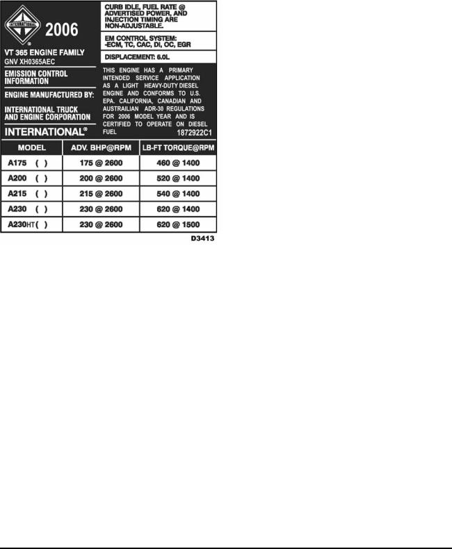
Emission Label (2006) Model Year
One emission label is on the right valve cover.
Figure 4 50 – State Exhaust Emissions Label (example)
The 50 – State Exhaust Emissions Label includes the following:
•Year the engine was certified to meet EPA emission standards
•Engine model code
•Service applications
•Advertised brake horsepower ratings
Engine accessories
The following engine accessories may have manufacturer’s labels or identification plates:
•Air compressor (for brake or suspension system )
•Air conditioning compressor
•Alternator
•Cooling fan clutch
•Variable Geometry Turbocharger (VGT)
•Power steering / fuel pump
•Starter motor
Labels or identification plates include information and specifications helpful to vehicle operators and technicians.
EGES295-2
Read all safety instructions in the "Safety Information" section of this manual before doing any procedures. Follow all warnings, cautions, and notes.
© 2006 International Truck and Engine Corporation

ENGINE SYSTEMS |
9 |
|
|
Engine Description
Table 1 Engine Features and Specifications
International® VT 365 engine features and specifications
Engine |
Diesel, 4 cycle |
Configuration |
4 OHV/1 Cam-in-Crankcase-V8 |
Displacement |
365 cu. in (6.0L) |
Bore and stroke |
95 mm x 105 mm (3.74 in x 4.134 in) |
Compression ratio |
18.0:1 |
Aspiration |
VGT turbocharged and Charge Air Cooling (CAC) |
Rated power @ rpm 1 |
175 bhp @ 2600 rpm |
Peak torque @ rpm 1 |
460 lbf•ft @ 1400 rpm |
Engine rotation, facing flywheel |
Counterclockwise |
Combustion system |
Digital Direct Injection (DDI) |
Total engine weight (auto with oil) |
459 kg (1094 lb) |
Cooling system capacity (engine only) |
10.2 liters (10.8 qts) |
Lube system capacity (including filter) |
18 liters (19 qts) |
Lube system capacity (dry) |
21.8 liters (23 qts) |
Firing order |
1–2–7–3–4–5–6–8 |
1 |
Base rating shown. See Appendix A for other ratings. |
|
Major features
Air Management System (AMS)
•Variable Geometry Turbocharger (VGT)
•Exhaust Gas Recirculation (EGR) system
•Chassis mounted Charge Air Cooling (CAC) Digital Direct fuel Injection (DDI)
Two piece crankcase
One piece cylinder head with four valves per cylinder Dual timing
Rear gear train
Closed crankcase ventilation Oil cooler
The firing order is 1-2-7-3-4-5-6-8. When viewing the engine from the rear (flywheel end), the right side cylinders are numbered 1, 3, 5, and 7. Number one is the front position. The left side is numbered 2, 4, 6, and 8.
A two piece crankcase has been specially designed to withstand the loads of diesel operation. The lower crankcase has integral main bearing caps. Coolant and oil passages are cast and machined in the crankcase and front cover housing.
The crankshaft has five main bearings with fore and aft thrust controlled at the upper half of the number 4 main bearing. Two connecting rods are attached to each crankshaft journal. The piston pin moves freely inside the piston and rod. Piston pin retaining rings secure the piston pin within the piston.
EGES295-2
Read all safety instructions in the "Safety Information" section of this manual before doing any procedures. Follow all warnings, cautions, and notes.
© 2006 International Truck and Engine Corporation

10 |
ENGINE SYSTEMS |
|
|
One piece aluminum alloy pistons are fitted with one keystone cut compression ring, one rectangular intermediate compression ring, and a two piece oil control ring. The combustion bowl (in the piston crown) reduces exhaust emissions.
The camshaft is supported by five insert bushings pressed into the crankcase. Two cam lobes, cam followers, push rods and valve bridges control four valves per cylinder. The camshaft is gear driven from the rear end of the crankshaft. A thrust flange is located between the camshaft gear and the crankcase. Camshaft thrust is controlled with the rear surface of the number 5 cam journal and the cam gear.
Hydraulic cam followers maintain zero valve lash and minimize engine noise. This eliminates periodic adjustment of valve lash. The hydraulic cam followers have rollers which provide excellent cam lobe and cam follower durability.
The lubrication system uses a crankshaft driven gerotor pump mounted on the front cover. The oil pressure regulator is built into the front cover and is accessible from outside the engine. Lube oil is routed through an oil cooler equipped with a pressure controlled bypass valve. Lube oil moves through passages in the crankcase to lubricate all internal components and to supply the piston cooling tubes and high pressure pump reservoir. The VGT and air compressor use external oil lines.
The VGT is electronically controlled and hydraulically actuated. The VGT provides boost control at low and high speeds for improved throttle response.
An exhaust gas recirculation valve allows water cooled exhaust gases to be fed into the inlet air stream to reduce exhaust emissions.
A closed crankcase breather system recirculates crankcase vapors back into the intake air system.
A chassis mounted Charge Air Cooler (CAC), an air-to-air heat exchanger, increases the density of the air charge.
Engine operation is controlled by two engine mounted control modules:
•Electronic Control Module (ECM)
•Injector Drive Module (IDM)
The ECM receives signals from engine and chassis mounted sensors. The ECM controls engine operation with the following actuators:
•IPR
•VGT control valve
•EGR
•Glow plug relay
The IDM controls fuel injector operation using data from the ECM.
EGES295-2
Read all safety instructions in the "Safety Information" section of this manual before doing any procedures. Follow all warnings, cautions, and notes.
© 2006 International Truck and Engine Corporation
ENGINE SYSTEMS |
11 |
|
|
Engine Component Locations
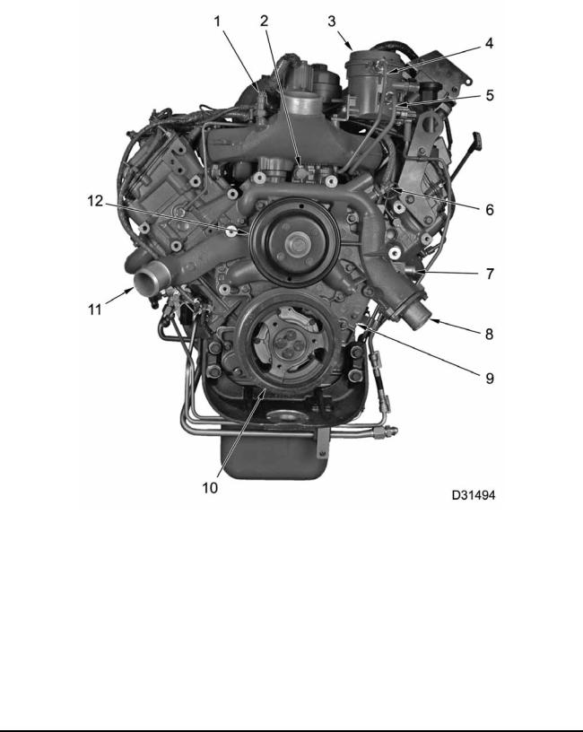
Figure 5 Engine components – Front
1. |
Manifold Absolute Pressure |
5. |
Fuel supply |
9. |
Front cover assembly |
|
(MAP) sensor |
6. |
Engine Coolant Temperature |
10. |
Crankshaft vibration damper |
2. |
Lube oil pressure test port |
|
(ECT) sensor |
11. |
Coolant inlet |
3. |
Fuel filter assembly |
7. |
Port for coolant deaeration tank |
12. |
Water pump pulley |
4. |
Fuel return |
8. |
Coolant outlet and thermostat |
|
|
EGES295-2
Read all safety instructions in the "Safety Information" section of this manual before doing any procedures. Follow all warnings, cautions, and notes.
© 2006 International Truck and Engine Corporation
12 |
ENGINE SYSTEMS |
|
|
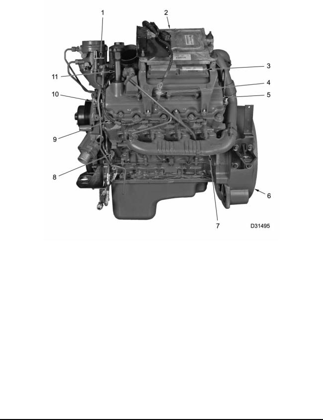
Figure 6 Engine components – Left
1. |
Fuel filter drain lever |
5. |
Valve cover |
10. |
Engine Coolant Temperature |
2. |
Engine Control Module (ECM) |
6. |
Rear cover |
|
(ECT) sensor |
3. |
Injector Driver Module (IDM) |
7. |
Exhaust manifold |
11. |
Lube oil fill tube |
4. |
Exhaust Back Pressure (EBP) |
8. |
Camshaft Position (CMP) sensor |
|
|
|
sensor |
9. |
Glow plug harness |
|
|
EGES295-2
Read all safety instructions in the "Safety Information" section of this manual before doing any procedures. Follow all warnings, cautions, and notes.
© 2006 International Truck and Engine Corporation
ENGINE SYSTEMS |
13 |
|
|
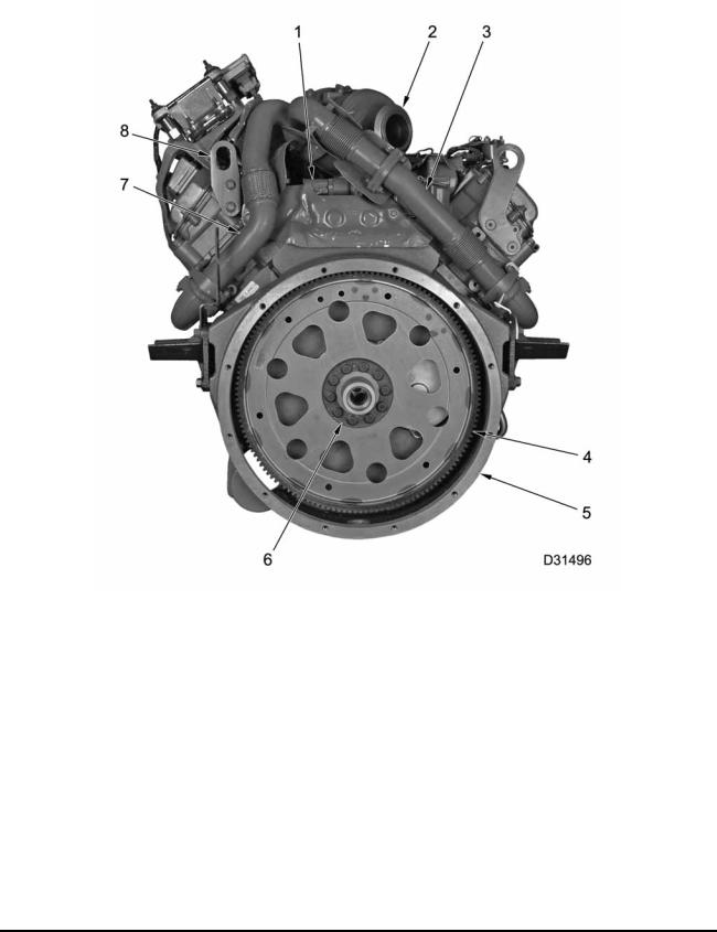
Figure 7 Engine components – Rear
1. |
Injection Pressure Regulator |
4. |
Flywheel or flexplate assembly |
7. |
Shielded exhaust tube assembly, |
|
(IPR valve) |
5. |
Rear cover assembly |
|
left |
2. |
Turbocharger exhaust outlet |
6. |
Reinforcement ring |
8. |
Lifting eye (3) |
3.Exhaust tube assembly, right
EGES295-2
Read all safety instructions in the "Safety Information" section of this manual before doing any procedures. Follow all warnings, cautions, and notes.
© 2006 International Truck and Engine Corporation
14 |
ENGINE SYSTEMS |
|
|
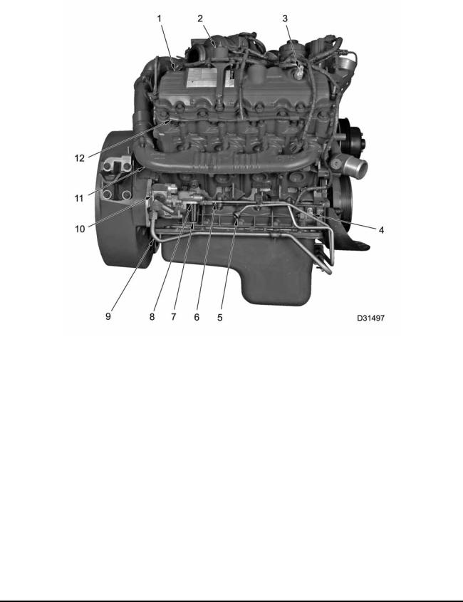
Figure 8 Engine components – Right
1. |
Valve cover |
5. |
Fuel return line |
11. |
Exhaust Manifold |
2. |
Glow plug relay |
6. |
Fuel supply line |
12. |
Glow plug harness |
3. |
Injection Control Pressure (ICP) |
7. |
Fuel filter strainer |
|
|
|
sensor |
8. |
Fuel supply pump (transfer) |
|
|
4. |
Crankshaft Position (CKP) |
9. |
Power steering line |
|
|
|
sensor |
10. |
Power steering pump |
|
|
EGES295-2
Read all safety instructions in the "Safety Information" section of this manual before doing any procedures. Follow all warnings, cautions, and notes.
© 2006 International Truck and Engine Corporation
ENGINE SYSTEMS |
15 |
|
|
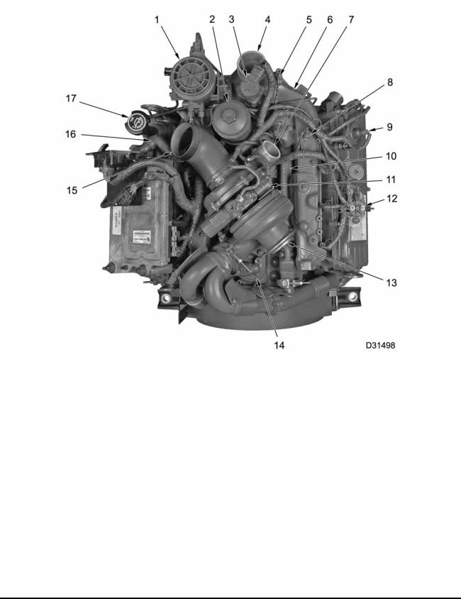
Figure 9 Engine components – Top
1. |
Fuel filter assembly |
6. |
Intake manifold |
12. |
Glow plug relay |
2. |
Oil filter housing |
7. |
Compressor outlet |
13. |
VGT |
3. |
Exhaust Gas Recirculation |
8. |
Manifold Air Temperature (MAT) |
14. |
High-pressure oil pump cover |
|
(EGR) valve |
|
sensor |
15. |
Air inlet duct |
4. |
Intake manifold air inlet |
9. |
ICP sensor |
16. |
Breather hose assembly with |
5. |
Manifold Absolute Pressure |
10. |
EGR cooler |
|
pitot tube |
|
(MAP) sensor |
11. |
VGT control valve |
17. |
Lube oil fill |
EGES295-2
Read all safety instructions in the "Safety Information" section of this manual before doing any procedures. Follow all warnings, cautions, and notes.
© 2006 International Truck and Engine Corporation
16 |
ENGINE SYSTEMS |
|
|
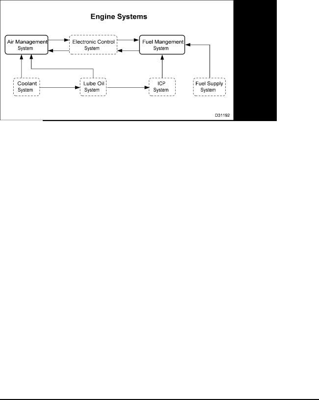
Engine Systems
The primary engine systems are Air Management and Fuel Management, which share some subsystems or have a subsystem that contributes to their operation.
•The Electronic Control System controls the Air Management System and Fuel Management System.
•The Coolant System provides heat transfer for EGR gases and lubrication oil.
•The ICP system uses lube oil for hydraulic fluid to actuate the fuel injectors.
•The Fuel Supply System pressurizes fuel for transfer to the fuel injectors.
•The Lube Oil System provides lubrication and heat transfer to engine components.
EGES295-2
Read all safety instructions in the "Safety Information" section of this manual before doing any procedures. Follow all warnings, cautions, and notes.
© 2006 International Truck and Engine Corporation
ENGINE SYSTEMS |
17 |
|
|
Air Management System (AMS)
Figure 11 Air Management System (AMS)
1. |
Intake manifold |
5. |
Shielded tube exhaust assembly |
9. |
Right exhaust manifold |
2. |
EGR cooler |
6. |
VGT with mounting bracket |
10. |
Exhaust tube assembly, right |
3. |
Left cylinder head |
7. |
Air inlet duct |
|
|
4. |
Left exhaust manifold |
8. |
Right cylinder head |
|
|
EGES295-2
Read all safety instructions in the "Safety Information" section of this manual before doing any procedures. Follow all warnings, cautions, and notes.
© 2006 International Truck and Engine Corporation

18 |
ENGINE SYSTEMS |
|
|
The Air Management system includes the following:
•Air filter assembly
•Closed crankcase breather
•Chassis mounted Charged Air Cooler (CAC)
•Variable Geometry Turbocharger (VGT)
•Intake manifold
•Exhaust Gas Recirculation (EGR) system
•Exhaust system
•Catalytic converter– dependent on application
•Catalyzed Diesel Particulate Filter (CDPF) – dependent on application
EGES295-2
Read all safety instructions in the "Safety Information" section of this manual before doing any procedures. Follow all warnings, cautions, and notes.
© 2006 International Truck and Engine Corporation
|
ENGINE SYSTEMS |
19 |
|
|
|
|
|
|
|
|
|
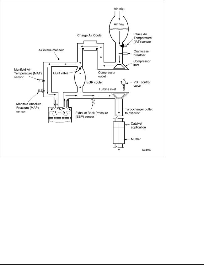
Figure 12 Air flow diagram
Air flow
Air enters and flows through the air filter assembly and mixes with air from crankcase ventilation. The VGT compresses the air mixture before it enters the Charge Air Cooler (CAC). Cooled compressed air flows from the CAC into the air intake manifold that directs air to the intake ports for each cylinder head.
After combustion, hot exhaust gas is forced through the exhaust manifolds to the EGR cooler and VGT.
•Some hot exhaust gas is cooled in the EGR cooler and flows through the EGR control valve back through the air intake manifold to mix with filtered air. This reduces nitrogen oxide (NOx) emissions and noise.
•The rest of the hot exhaust gas expands and flows to the VGT, spins the turbine wheel, and flows from the VGT outlet to the engine exhaust pipe.
•The VGT compressor wheel, on the same shaft as the turbine wheel, compresses the mixture of filtered air and air from crankcase ventilation.
The VGT responds directly to engine loads. During heavy load, an increased flow of exhaust gases turns the turbine wheel faster. This increased speed turns the compressor impeller faster and supplies more air or greater boost to the intake manifold. Conversely, when engine load is light, the flow of exhaust gases decreases and less air is pumped into the intake manifold.
EGES295-2
Read all safety instructions in the "Safety Information" section of this manual before doing any procedures. Follow all warnings, cautions, and notes.
© 2006 International Truck and Engine Corporation
20 |
ENGINE SYSTEMS |
|
|
|
|
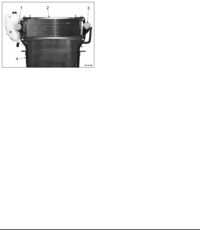
The VGT modifies more efficient |
exhaust flow |
The CAC cooler is mounted on top of the radiator. |
characteristics. |
|
Air from the VGT is pushed through a network of |
|
|
heat exchanger tubes before entering the air intake |
Charge Air Cooler (CAC) |
|
manifold. Outside air flowing over the tubes and |
|
fins cools the charged air. Charged air is cooler and |
|
|
|
denser than the uncooled air; cooler and denser |
|
|
air improves the fuel-to-air ratio during combustion, |
|
|
resulting in improved emission control and power |
|
|
output. |
Figure 13 Charge Air Cooler
1.Air outlet
2.Charge Air Cooler
3.Air inlet
4.Radiator
EGES295-2
Read all safety instructions in the "Safety Information" section of this manual before doing any procedures. Follow all warnings, cautions, and notes.
© 2006 International Truck and Engine Corporation
ENGINE SYSTEMS |
21 |
|
|
Variable Geometry Turbocharger (VGT)
Figure 14 |
VGT |
|
|
|
1. |
Actuator |
3. |
Unison ring |
|
2. |
VGT control valve |
4. |
Vanes |
|
The |
key |
feature of the VGT is |
actuated vanes VGT closed loop system |
|
in the turbine housing. The vanes modify flow characteristics of exhaust gases through the turbine housing. The benefit is the ability to control boost pressure needed to accommodate various engine speeds and load conditions. An additional benefit is lower exhaust emissions.
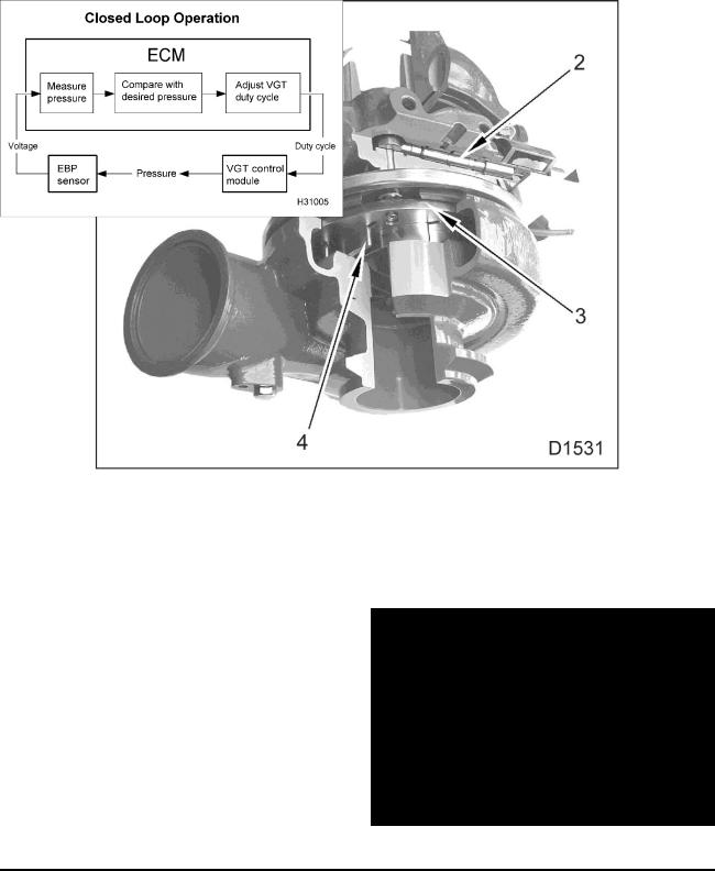
Figure 15 VGT closed loop system
EGES295-2
Read all safety instructions in the "Safety Information" section of this manual before doing any procedures. Follow all warnings, cautions, and notes.
© 2006 International Truck and Engine Corporation
22 |
ENGINE SYSTEMS |
|
|
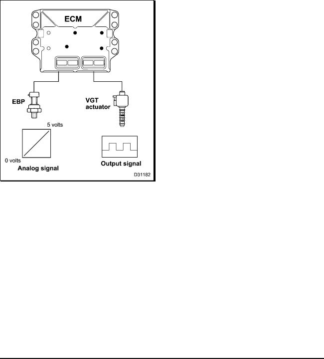
The VGT is a closed loop system that uses the Exhaust Back Pressure (EBP) sensor to provide feedback to the ECM. The ECM uses the EBP sensor to continuously monitor EBP and adjust the duty cycle to the VGT to match engine requirements.
VGT control
Figure 16 VGT control
The solenoid receives a pulse width modulated signal from the ECM that indicates the on / off time that the control valve is energized. The control valve directs lube oil flow to both sides of the piston in the actuator housing. Directing oil to different sides of the piston increases or decreases exhaust back pressure.
Actuated vanes are mounted around the inside circumference of the turbine housing. A unison ring
links all the vanes. When the unison ring moves, all vanes move to the same position. Unison ring movement occurs when either side of the actuator piston is pressurized by engine oil.
Exhaust gas flow can be regulated depending on required exhaust back pressure for engine speed and load.
Exhaust Gas Recirculation (EGR) System
The EGR system includes the following:
•EGR drive module
•EGR valve
•EGR cooler
•Air intake manifold
•Exhaust tube assembly, right
The Exhaust Gas Recirculation (EGR) system reduces Nitrogen Oxide (NOx) emissions.
NOX forms during a reaction between nitrogen and oxygen at high temperature during combustion. Combustion starts when fuel is injected into the cylinder before or slightly after the piston reaches top-dead-center.
EGR flow
Some exhaust from the right exhaust tube assembly flows into the EGR cooler. Exhaust from the EGR cooler flows into a passage in the air intake manifold that intersects with the EGR valve.
When EGR is commanded, the EGR control valve opens allowing cooled exhaust gases to enter the intake manifold to be mixed with filtered intake air then recycled through the combustion process.
EGES295-2
Read all safety instructions in the "Safety Information" section of this manual before doing any procedures. Follow all warnings, cautions, and notes.
© 2006 International Truck and Engine Corporation

ENGINE SYSTEMS |
23 |
|
|
EGR valve
Figure 18 EGR control
The EGR valve, installed in the top front of the air intake manifold, has three major components: a two head valve assembly, a DC motor, and an Integrated Circuit (IC). The IC has three Hall effect position sensors that monitor valve movement.
The EGR drive module, mounted on the EGR drive module mounting bracket above the ECM/IDM assembly, controls the DC motor.
Figure 17 EGR valve
1.Actuator coil
2.Valve heads (2)
3.Common shaft
A DC motor, in EGR valve, moves and controls the position of a two head valve assembly.
Figure 19 EGR closed loop operation
EGES295-2
Read all safety instructions in the "Safety Information" section of this manual before doing any procedures. Follow all warnings, cautions, and notes.
© 2006 International Truck and Engine Corporation

24 |
ENGINE SYSTEMS |
|
|
The EGR system is closed loop control, using EGR position signals.
The EGR drive module receives the desired EGR valve position from the ECM across the CAN 2 datalink to activate the EGR valve for exhaust gas recirculation. The EGR drive module provides feedback to the ECM on the valve position, interprets the ECM command, and sends the command using three pulse width modulated signals to the DC motor.
Exhaust System
The exhaust system includes the following:
•Exhaust valves
•Exhaust manifolds
•Turbocharger
•Exhaust piping
•Muffler and catalytic converter – dependent on application
•Catalyzed Diesel Particulate Filter (CDPF) – if equipped.
The exhaust system removes exhaust gases from the engine. Exhaust gases exit from exhaust ports, through exhaust valves, and flow into the exhaust manifolds. Expanding exhaust gases are directed through the exhaust tubes. The right exhaust tube directs some exhaust gases into the Exhaust Gas Recirculation (EGR) cooler. Exhaust gases flowing into the VGT drive the turbine wheel. Exhaust gases exit the VGT and flow into the exhaust piping, through the muffler and catalytic converter or CDPF, and out the discharge pipe to the atmosphere.
EGES295-2
Read all safety instructions in the "Safety Information" section of this manual before doing any procedures. Follow all warnings, cautions, and notes.
© 2006 International Truck and Engine Corporation
ENGINE SYSTEMS |
25 |
|
|
Fuel Management System
Fuel Injection
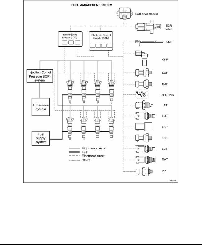
Figure 20 Fuel management system |
|
|
|
The fuel management system includes the following: |
• |
Electronic control system |
|
• |
Injection Control Pressure (ICP) system |
• |
Lubrication system |
• |
Fuel injectors |
• |
Fuel supply system |
EGES295-2
Read all safety instructions in the "Safety Information" section of this manual before doing any procedures. Follow all warnings, cautions, and notes.
© 2006 International Truck and Engine Corporation
26 |
ENGINE SYSTEMS |
|
|
Injection Control Pressure (ICP) System
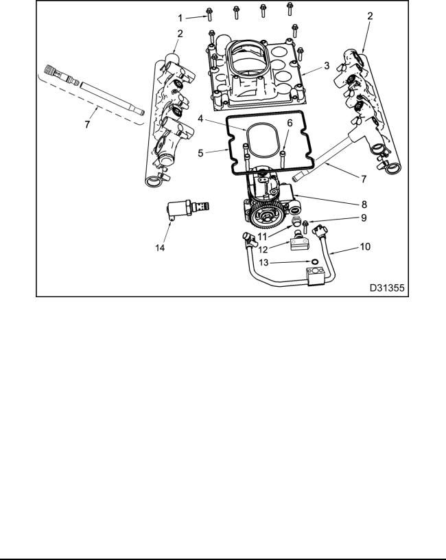
Figure 21 High-pressure oil system
1. |
High-pressure oil pump cover |
6. |
High-pressure oil pump |
11. |
Snap to Connection (STC) fitting |
|
fasteners (8) |
|
fasteners (3) |
12. |
Branch tube adapter |
2. |
Oil rail assembly (2) |
7. |
Case-to-head tube assembly (2) |
13. |
O-ring |
3. |
High-pressure oil pump cover |
8. |
High-pressure oil pump |
14. |
IPR valve |
4. |
Pump-to-cover seal ring |
|
assembly |
|
|
5. |
High-pressure oil pump cover |
9. |
Branch tube adapter bolt (2) |
|
|
|
seal |
10. |
Branch tube assembly |
|
|
High-pressure Oil Flow |
|
|
|
A |
gear driven, high-pressure |
oil pump |
draws |
oil |
through a screen in the oil |
reservoir |
for the |
high-pressure oil pump. The oil reservoir, in the top of the crankcase below the oil cooler, is kept full by the engine lubrication system.
The IPR valve maintains the ICP pressure by dumping excess oil back to the crankcase.
High-pressure oil from the pump flows through a branch tube assembly to each case-to-head tube assembly to each high-pressure oil rail.
High-pressure oil in the oil rails enter the fuel injectors through sealed ports in the top of the fuel injectors.
When the OPEN coil for each injector is energized, the injector uses high-pressure oil to inject and atomize fuel into the combustion chamber. The CLOSE coils are energized to end injection. Exhaust oil exits through two ports in the top of the injector and drains back to the crankcase.
EGES295-2
Read all safety instructions in the "Safety Information" section of this manual before doing any procedures. Follow all warnings, cautions, and notes.
© 2006 International Truck and Engine Corporation
 Loading...