


VT 275 V6

®
VT 275 V6 ENGINE
model year 2005

FORWARD
This publication is intended to provide technicians and service personnel with an overview of technical features of the
International
service literature. Consult the latest SERVICE and DIAGNOSTIC manuals before conducting any service or repairs.
®
VT 275 Diesel Engine. The information contained in this publication will supplement information contained in available
Safety Information
s
BBaatttteerriiees
This manual provides general and specific service procedures
and repair methods essential for reliable engine operation and
your safety. Since many variations in procedures, tools, and
service parts are involved, advice for all possible safety
conditions and hazards cannot be stated.
Departure from instructions in this manual or disregard of
warnings and cautions can lead to injury, death, or both, and
damage to the engine or vehicle.
Read safety instructions below before doing service and test
procedures in this manual for the engine or vehicle. See related
application manuals for more information.
Safety Instructions
e
VVeehhiicclle
• Make sure the vehicle is in neutral, the parking brake is set,
and the wheels are bloc
diagnostic procedures on the engine or vehicle.
ked before doing any work or
• Batteries produce highly flammable gas during and after
c
harging.
• Always disconnect the main negative battery cable first.
• Always connect the main negative battery cable last.
• Avoid leaning over batteries.
• Protect your eyes.
• Do not expose batteries to open flames or sparks.
• Do not smoke in workplace.
CCoommpprreesssseedd AAiir
• Limit shop air pressure for blow gun to 207 kPa (30psi).
• Use approved equipment.
• Do not direct air at b
r
ody or clothing.
WWoorrkk AArreea
• Keep area clean, dry and organized.
• K
• Make sure the work area is ventilated and well lit.
• Make sure a First Aid Kit is available.
SSaaffeettyy EEqquuiippmmeennt
• Use correct lifting devices.
• Use saf
PPrrootteeccttiivvee MMeeaassuurrees
• Wear protective glasses and saf
bare feet, sandals, or sneakers).
• Wear appropriate hearing protection.
• Wear correct clothing.
• Do not wear rings, watches, or other jewelry.
• Restrain long hair.
FFiirree pprreevveennttiioon
• Make sure charged fire extinguishers are in the work area.
NNOOTTEE:
ensure that the following fire types can be extinguished.
a
eep tools and parts off the floor.
t
ety blocks and stands.
s
ety shoes (do not work in
n
:
Check the classification of eac
1. Type A - Wood, paper, textiles, and rubbish
2. Type B - Flammable liquids
3. Type C - Electrical equipment
h fire extinguisher to
• Wear safety glasses or goggles.
• Wear hearing protection.
• Use shielding to protect others in the work area.
s
TToooolls
• Make sure all tools are in good condition.
• Make sure all standard electrical tools are grounded.
• Check for frayed power cords before using power tools.
FFlluuiiddss UUnnddeerr PPrreessssuurre
• Use extreme caution when working on systems
under pressure.
• F
ollow approved procedures only.
l
FFuueel
• Do not over fill fuel tank. Over fill creates a fire hazard.
• Do not smoke in the work area.
• Do not refuel the tank when the engine is running.
RReemmoovvaall ooff TToooollss,, PPaarrttss,, aanndd EEqquuiippmmeennt
• Reinstall all safety guards, shields and covers after servicing
the engine.
• Make sure all tools, parts, and service equipment are
removed from the engine and vehicle after all work is done.
e
t
2
International®VT 275 V6 Engine

TABLE OF CONTENTS
OVERVIEW . . . . . . . . . . . . . . . . . . . . . . . . . . . . . . . . . . . . . . . . . . . . . . . . . . . .6
COMPONENT LOCATIONS . . . . . . . . . . . . . . . . . . . . . . . . . . . . . . . . . . . . . . . .8
DESIGN FEATURES . . . . . . . . . . . . . . . . . . . . . . . . . . . . . . . . . . . . . . . . . . . .18
ELECTRONIC CONTROL SYSTEM . . . . . . . . . . . . . . . . . . . . . . . . . . . . . . . . . .22
AIR MANAGEMENT SYSTEM . . . . . . . . . . . . . . . . . . . . . . . . . . . . . . . . . . . . .40
FUEL SUPPLY SYSTEM . . . . . . . . . . . . . . . . . . . . . . . . . . . . . . . . . . . . . . . . .48
FUEL MANAGEMENT SYSTEM . . . . . . . . . . . . . . . . . . . . . . . . . . . . . . . . . . . .52
INJECTOR OPERATION . . . . . . . . . . . . . . . . . . . . . . . . . . . . . . . . . . . . . . . . .56
LUBRICATION SYSTEM . . . . . . . . . . . . . . . . . . . . . . . . . . . . . . . . . . . . . . . . .60
COOLING SYSTEM . . . . . . . . . . . . . . . . . . . . . . . . . . . . . . . . . . . . . . . . . . . . .68
UNIQUE REPAIR PROCEDURES . . . . . . . . . . . . . . . . . . . . . . . . . . . . . . . . . . .72
SPECIAL TOOLS . . . . . . . . . . . . . . . . . . . . . . . . . . . . . . . . . . . . . . . . . . . . . . .86
DIAGNOSTIC PROCEDURES . . . . . . . . . . . . . . . . . . . . . . . . . . . . . . . . . . . . . .90
DIAGNOSTIC TROUBLE CODES . . . . . . . . . . . . . . . . . . . . . . . . . . . . . . . . . .100
ENGINE & CHASSIS SCHEMATIC . . . . . . . . . . . . . . . . . . . . . . . . . . . . . . . . .102
POWER DISTRIBUTION CENTER FUSES . . . . . . . . . . . . . . . . . . . . . . . . . . .104
GLOSSARY . . . . . . . . . . . . . . . . . . . . . . . . . . . . . . . . . . . . . . . . . . . . . . . . . .106
INDEX . . . . . . . . . . . . . . . . . . . . . . . . . . . . . . . . . . . . . . . . . . . . . . . . . . . . . .108
International®VT 275 V6 Engine
3

4

DIRECT INJECTION TURBOCHARGED DIESEL ENGINE
VT 275 FEATURES
• 90° V6
• Offset Crankpins
• Rear Gear Train
• Primary Balancer
• Regulated Two-Stage Turbocharging System
• Four Valves per Cylinder
• Cooled Exhaust Gas Recirculation
• Electro-Hydraulic Generation 2 Fuel Injection System
• Top Mounted Oil and Fuel Filters
International®VT 275 V6 Engine
5

VT 275 OVERVIEW
0
50
100
150
200
250
300
350
400
450
500
600
800
1000
1200
1400
1600
1800
2000
2200
2400
2600
2800
3000
3200
3400
3600
0
25
50
75
100
125
150
175
200
225
250
Torque (ft-lb)
Power (HP)
Engine Speed (RPM)
Load (ft-lb)
Power (HP)
Power & Torque Curve
VT 275 ENGINE SPECIFICATIONS
Engine Type . . . . . . . . . . . . . . . . . . . . . . . . . . . . . . . . . . . . . . . . 4-stroke, direct injection diesel
Configuration . . . . . . . . . . . . . . . . . . . . . . . . . . . . V6, pushrod operated four valves / cylinder
Displacement . . . . . . . . . . . . . . . . . . . . . . . . . . . . . . . . . . . . . . . . . . . . . . 275 cu. in. (4.5 liters)
Bore . . . . . . . . . . . . . . . . . . . . . . . . . . . . . . . . . . . . . . . . . . . . . . . . . . . . . . . . . 3.74 in. (95 mm)
Stroke . . . . . . . . . . . . . . . . . . . . . . . . . . . . . . . . . . . . . . . . . . . . . . . . . . . . . 4.134 in. (105 mm)
Compression Ratio . . . . . . . . . . . . . . . . . . . . . . . . . . . . . . . . . . . . . . . . . . . . . . . . . . . . . . 18.0:1
Aspiration . . . . . . . . . . . . . . . . . . . . . . . . . . . . . . . . . Twin turbocharged and charge air cooled
Rated Power . . . . . . . . . . . . . . . . . . . . . . . . . . . . . . . . . . . . . . . . . . . . . . . . 200 hp @ 2700 rpm
Peak Torque . . . . . . . . . . . . . . . . . . . . . . . . . . . . . . . . . . . . . . . . . . . . . . . 440 lb-ft @ 1800 rpm
Engine Rotation, Facing the Flywheel . . . . . . . . . . . . . . . . . . . . . . . . . . . . . Counterclockwise
Injection System . . . . . . . . . . . . . . . . . . . . . . . . . Electro-hydraulic generation 2 fuel injection
Cooling System Capacity (Engine Only) . . . . . . . . . . . . . . . . . . . . . . . . . . . . . . . . . . 11 quarts
Lube System Capacity (Engine Only) . . . . . . 13 quarts with oil filter (14 quarts at overhaul)
Slide Title Goes Here
Horsepower and Torque
• The VT 275 engine is offered with only one
horsepower and torque rating for the 2005
model year. The engine creates 200
horsepower at 2700 rpm and 440 lb-ft of
torque at 1800 rpm. The engine has a
high idle speed of 2775 rpm with
automatic transmission. The engine idle
speed is set at 700 rpm and is not adjustable.
6
International®VT 275 V6 Engine
Engine Serial Number
2
4
6
5
3
1
Front
L
R
• The Engine Serial Number (ESN) for the
VT 275 is located on a machined surface
at the left rear corner of the crankcase just
below the cylinder head.
• The ESN identifies the engine family, the
build location, and the sequential
build number.
• Engine Serial Number Example
4.5HM2Y0135617
4.5 = Engine displacement
H = Diesel, T
M2 = Motor Truck
Y = Huntsville
0135617 = Build Sequence
urbocharged
Emissions Label
• The Environmental Protection Agency
(EPA) emissions label is on top of the
breather, toward the front, on the left valve
cover. The label includes the following:
VT 275 OVERVIEW
-Advertised horsepower rating
-Engine model code
-Service application
-Emission family and control system
-Year the engine was certified to meet EPA
emission standards.
Cylinder Numbering
• The cylinders on the VT 275 are numbered
from the front of the right bank 1, 3, 5 and
from the front of the left bank 2, 4 and 6.
• The engine firing order is 1-2-5-6-3-4
International®VT 275 V6 Engine
7

COMPONENT LOCATIONS - FRONT OF ENGINE
AAIIRR IINNLLEETT HHEEAATTEERR
HHEEAATTEERR SSUUPPPPLLYY TTUUBBEE
HHEEAATTEERR SSUUPPPPLLYY TTUUBBEE
SSMMOOOOTTHH IIDDLLEERR PPUULLLLEEYY
SSMMOOOOTTHH IIDDLLEERR PPUULLLLEEYY
AAIIRR IINNLLEETT HHEEAATTEERR
AAIIRR IINNLLEETT
AAIIRR IINNLLEETT
IINNTTAAKKEE MMAANNIIFFOOLLDD
IINNTTAAKKEE MMAANNIIFFOOLLDD
BBAANNJJOO BBOOLLTT WWIITTHH
BBAANNJJOO BBOOLLTT WWIITTHH
CCHHEECCKK VVAALLVVEE
CCHHEECCKK VVAALLVVEE
FFUUEELL TTUUBBEE TTOO RRIIGGHHTT BBAANNKK
FFUUEELL TTUUBBEE TTOO RRIIGGHHTT BBAANNKK
MMAATT SSEENNSSOORR
MMAATT SSEENNSSOORR
PPOOWWEERR SSTTEEEERRIINNGG
PPOOWWEERR SSTTEEEERRIINNGG
PPUUMMPP BBRRAACCKKEETT
PPUUMMPP BBRRAACCKKEETT
BBEELLTT TTEENNSSIIOONNEERR
BBEELLTT TTEENNSSIIOONNEERR
OOIILL PPUUMMPP CCOOVVEERR
OOIILL PPUUMMPP CCOOVVEERR
8
International®VT 275 V6 Engine

COMPONENT LOCATIONS - LEFT FRONT OF ENGINE
GGRROOOOVVEEDD IIDDLLEERR PPUULLLLEEYY
GGRROOOOVVEEDD IIDDLLEERR PPUULLLLEEYY
BBRREEAATTHHEERR
BBRREEAATTHHEERR
SSMMOOOOTTHH IIDDLLEERR PPUULLLLEEYY
SSMMOOOOTTHH IIDDLLEERR PPUULLLLEEYY
RREETTUURRNN TTUUBBEE
RREETTUURRNN TTUUBBEE
CCOOOOLLAANNTT OOUUTTLLEETT
CCOOOOLLAANNTT OOUUTTLLEETT
HHEEAATTEERR
HHEEAATTEERR
International®VT 275 V6 Engine
9

COMPONENT LOCATIONS - LEFT SIDE OF ENGINE
AAIIRR IINNLLEETT DDUUCCTT
AAIIRR IINNLLEETT DDUUCCTT
OOIILL LLEEVVEELL
OOIILL LLEEVVEELL
LLEEFFTT BBAANNKK
LLEEFFTT BBAANNKK
GGLLOOWW PPLLUUGGSS
GGLLOOWW PPLLUUGGSS
GGAAUUGGEE
GGAAUUGGEE
10
CCMMPP SSEENNSSOORR
CCMMPP SSEENNSSOORR
FFUUEELL RREETTUURRNN TTOO TTAANNKK
FFUUEELL RREETTUURRNN TTOO TTAANNKK
International®VT 275 V6 Engine
SSUUPPPPLLYY FFRROOMM FFUUEELL PPUUMMPP
SSUUPPPPLLYY FFRROOMM FFUUEELL PPUUMMPP
AANNDD PPRRIIMMAARRYY FFIILLTTEERR
AANNDD PPRRIIMMAARRYY FFIILLTTEERR

IIPPRR AANNDD
IIPPRR AANNDD
HHEEAATT SSHHIIEELLDD
HHEEAATT SSHHIIEELLDD
COMPONENT LOCATIONS - LEFT REAR OF ENGINE
LLIIFFTTIINNGG EEYYEESS
LLIIFFTTIINNGG EEYYEESS
LLEEFFTT BBAANNKK
LLEEFFTT BBAANNKK
EEXXHHAAUUSSTT MMAANNIIFFOOLLDD
EEXXHHAAUUSSTT MMAANNIIFFOOLLDD
RREEAARR CCOOVVEERR
RREEAARR CCOOVVEERR
International®VT 275 V6 Engine
11
COMPONENT LOCATIONS - REAR OF ENGINE
OOIILL FFIILLTTEERR HHOOUUSSIINNGG
OOIILL FFIILLTTEERR HHOOUUSSIINNGG
FFUUEELL FFIILLTTEERR HHOOUUSSIINNGG
FFUUEELL FFIILLTTEERR HHOOUUSSIINNGG
TTUURRBBIINNEE OOUUTTLLEETT
TTUURRBBIINNEE OOUUTTLLEETT
EEXXHHAAUUSSTT TTUUBBEE AASSSSEEMMBBLLYY
EEXXHHAAUUSSTT TTUUBBEE AASSSSEEMMBBLLYY
HHIIGGHH PPRREESSSSUURREE PPUUMMPP CCOOVVEERR
HHIIGGHH PPRREESSSSUURREE PPUUMMPP CCOOVVEERR
12
International®VT 275 V6 Engine

COMPONENT LOCATIONS - RIGHT REAR OF ENGINE
HHIIGGHH PPRREESSSSUURREE CCOOMMPPRREESSSSOORR HHOOUUSSIINNGG
HHIIGGHH PPRREESSSSUURREE CCOOMMPPRREESSSSOORR HHOOUUSSIINNGG
CCOOOOLLAANNTT
CCOOOOLLAANNTT
HHEEAATTEERR
HHEEAATTEERR
UUPPPPEERR OOIILL PPAANN
UUPPPPEERR OOIILL PPAANN
LLOOWWEERR OOIILL PPAANN
LLOOWWEERR OOIILL PPAANN
International®VT 275 V6 Engine
13

COMPONENT LOCATIONS - RIGHT SIDE OF ENGINE
OOUUTTLLEETT TTOO CCHHAARRGGEE AAIIRR CCOOOOLLEERR
OOUUTTLLEETT TTOO CCHHAARRGGEE AAIIRR CCOOOOLLEERR
TTUURRBBOOCCHHAARRGGEERR CCRROOSSSSOOVVEERR TTUUBBEE
TTUURRBBOOCCHHAARRGGEERR CCRROOSSSSOOVVEERR TTUUBBEE
IICCPP
IICCPP
SSEENNSSOORR
SSEENNSSOORR
RRIIGGHHTT BBAANNKK
RRIIGGHHTT BBAANNKK
GGLLOOWW PPLLUUGGSS
GGLLOOWW PPLLUUGGSS
CCRRAANNKKCCAASSEE
CCRRAANNKKCCAASSEE
LLOOWWEERR
LLOOWWEERR
CCRRAANNKKCCAASSEE
CCRRAANNKKCCAASSEE
CCKKPP SSEENNSSOORR
CCKKPP SSEENNSSOORR
14
International®VT 275 V6 Engine

COMPONENT LOCATIONS - RIGHT FRONT OF ENGINE
PPNNEEUUMMAATTIICC AACCTTUUAATTOORR
PPNNEEUUMMAATTIICC AACCTTUUAATTOORR
BBOOOOSSTT CCOONNTTRROOLL SSOOLLEENNOOIIDD
BBOOOOSSTT CCOONNTTRROOLL SSOOLLEENNOOIIDD
MMAAPP
MMAAPP
SSEENNSSOORR
SSEENNSSOORR
EECCTT
EECCTT
SSEENNSSOORR
SSEENNSSOORR
WWAATTEERR PPUUMMPP
WWAATTEERR PPUUMMPP
PPUULLLLEEYY
PPUULLLLEEYY
AANNDD FFAANN DDRRIIVVEE
AANNDD FFAANN DDRRIIVVEE
International®VT 275 V6 Engine
15
COMPONENT LOCATIONS - TOP OF ENGINE WITHOUT HARNESS
HHIIGGHH PPRREESSSSUURREE PPUUMMPP
HHIIGGHH PPRREESSSSUURREE PPUUMMPP
IINNJJEECCTTOORR CCOONNNNEECCTTOORRSS
IINNJJEECCTTOORR CCOONNNNEECCTTOORRSS
HHIIGGHH PPRREESSSSUURREE TTUURRBBIINNEE HHOOUUSSIINNGG
HHIIGGHH PPRREESSSSUURREE TTUURRBBIINNEE HHOOUUSSIINNGG
EEGGRR VVAALLVVEE
EEGGRR VVAALLVVEE
LLOOWW PPRREESSSSUURREE TTUURRBBOO CCOOMMPPRREESSSSOORR HHOOUUSSIINNGG
LLOOWW PPRREESSSSUURREE TTUURRBBOO CCOOMMPPRREESSSSOORR HHOOUUSSIINNGG
TTUURRBBOOCCHHAARRGGEERR
TTUURRBBOOCCHHAARRGGEERR
OOIILL SSUUPPPPLLYY LLIINNEE
OOIILL SSUUPPPPLLYY LLIINNEE
EEOOPP SSWWIITTCCHH
EEOOPP SSWWIITTCCHH
EEOOTT SSEENNSSOORR
EEOOTT SSEENNSSOORR
16
International®VT 275 V6 Engine

COMPONENT LOCATIONS - TOP OF ENGINE WITH HARNESS
MMAAFF SSEENNSSOORR CCOONNNNEECCTTOORR
MMAAFF SSEENNSSOORR CCOONNNNEECCTTOORR
((SSEENNSSOORR NNOOTT SSHHOOWWNN))
((SSEENNSSOORR NNOOTT SSHHOOWWNN))
IINNJJEECCTTOORR HHAARRNNEESSSS CCOONNNNEECCTTOORR
IINNJJEECCTTOORR HHAARRNNEESSSS CCOONNNNEECCTTOORR
HHAARRNNEESSSS TTOO
HHAARRNNEESSSS TTOO
CCHHAASSSSIISS MMOOUUNNTTEEDD
CCHHAASSSSIISS MMOOUUNNTTEEDD
EECCMM//IIDDMM
EECCMM//IIDDMM
BBOOOOSSTT CCOONNTTRROOLL SSOOLLEENNOOIIDD
BBOOOOSSTT CCOONNTTRROOLL SSOOLLEENNOOIIDD
AALLTTEERRNNAATTOORR FFUUSSIIBBLLEE LLIINNKKSS
AALLTTEERRNNAATTOORR FFUUSSIIBBLLEE LLIINNKKSS
((AALLTTEERRNNAATTOORR NNOOTT SSHHOOWWNN))
((AALLTTEERRNNAATTOORR NNOOTT SSHHOOWWNN))
International®VT 275 V6 Engine
17

VT 275 DESIGN FEATURES
RROOCCKKEERR AARRMM CCAARRRRIIEERR
RROOCCKKEERR AARRMM CCAARRRRIIEERR
RROOCCKKEERR AARRMM
RROOCCKKEERR AARRMM
RROOCCKKEERR AARRMM FFUULLCCRRUUMM
RROOCCKKEERR AARRMM FFUULLCCRRUUMM
Cylinder Head Assembly
• The VT 275 has an aluminum rocker arm
carrier for each cylinder head. The carrier
holds the fulcrum plates and the attached
rocker arms and can be removed as an
assembly from the cylinder head without
removing the rocker arms.
• Each rocker arm pivots on a steel ball
located by detents in the fulcrum plate.
Four head bolts on each cylinder head
pass through the two single and two dual
fulcrum plates serving to clamp the plates
to the carrier.
• The cylinder head is sealed to the
crankcase deck surface with a shim type
gasket that must be replaced if any of the
head bolts are removed. The 14mm head
bolts are torque to yield and cannot
be reused.
• The carrier is sealed to the cylinder head
with a push-in-place gasket. The cylinder
head and carrier are clamped to the
crankcase with eight 14mm bolts. Six
additional 8mm bolts around the perimeter
clamp the carrier to the cylinder head and
four additional 8mm bolts serve to clamp
the top of the head to the crankcase. Two
hollow dowels in the cylinder head are
used to align the rocker arm carrier to the
cylinder head.
IINNJJEECCTTOORR
PPAASSSS--
TTHHRROOUUGGHH
DDUUAALL FFUULLCCRRUUMM PPLLAATTEE
HHEEAADD BBOOLLTTSS
SSIINNGGLLEE
FFUULLCCRRUUMM
PPLLAATTEE
18
88mmmm FFUULLCCRRUUMM BBOOLLTT
GGLLOOWW PPLLUUGG
CCOONNNNEECCTTOORR OOPPEENNIINNGG
International®VT 275 V6 Engine
Rocker Arm Carrier
• The rocker arm carrier serves as an
attachment point for the fulcrum plates and
the rocker arms. In addition to the head
bolts, single fulcrum plates are attached to
the rocker arm carrier with one 8mm bolt.
The dual fulcrum plates are attached with
two 8mm bolts. The fulcrum plates are
marked with E and I as assembly aids to
show the valves they support. The E and I
must be visible after assembly to the head.
In addition, the carrier provides a passage
for each snap-in-place injector passthrough and the push-in-place glow
plug connectors.

VT 275 DESIGN FEATURES
Crankcase Assembly
• The VT 275 has four main bearings but
replaces the traditional individual main
bearing caps with a one-piece lower
crankcase assembly. The lower crankcase
is made of cast iron and is stronger than
the individual caps. The lower crankcase is
attached to the crankcase with sixteen
14mm main bearing bolts of two lengths
with the shorter bolts to the outside. Three
additional 8mm bolts are used on each
side at the perimeter. The lower crankcase
is sealed to the crankcase with two pushin-place seals.
Crankcase and Oil Pan
• The upper oil pan bolts to the lower
crankcase and is sealed with a full
perimeter push-in-place gasket. The lower
sheet metal oil pan is sealed to the upper
cast aluminum oil pan with a full perimeter
push-in-place gasket. The upper oil pan is
wider than the crankcase and allows for
greater oil pan capacity without
increased depth.
1144mmmm MMAAIINN BBEEAARRIINNGG BBOOLLTTSS
1144mmmm MMAAIINN BBEEAARRIINNGG BBOOLLTTSS
LLOOWWEERR OOIILL PPAANN
LLOOWWEERR OOIILL PPAANN
OOIILL PPIICCKK--UUPP TTUUBBEE
OOIILL PPIICCKK--UUPP TTUUBBEE
LLOOWWEERR CCRRAANNKKCCAASSEE
LLOOWWEERR CCRRAANNKKCCAASSEE
88mmmm BBOOLLTTSS
UUPPPPEERR OOIILL PPAANN
UUPPPPEERR OOIILL PPAANN
• The oil pickup is sealed to the upper oil
pan with an O-ring and attached with two
6mm bolts. Oil pulled through the oil
pickup tube passes through a passage
cast in the upper oil pan to the lower
crankcase. The lower crankcase has a
machined passage that takes oil to a front
cover passage that leads to the oil pump.
Openings in the upper oil pan allow oil to
return to the pan during engine operation
but also serve to keep oil in the pan away
from the rotating crankshaft.
CCRRAANNKKSSHHAAFFTT
CCRRAANNKKSSHHAAFFTT
UUPPPPEERR
UUPPPPEERR
CCRRAANNKKCCAASSEE
CCRRAANNKKCCAASSEE
LLOOWWEERR
LLOOWWEERR
CCRRAANNKKCCAASSEE
CCRRAANNKKCCAASSEE
International®VT 275 V6 Engine
19
VT 275 DESIGN FEATURES
CCAAMMSSHHAAFFTT
GGEEAARR
BBAALLAANNCCEERR SSHHAAFFTT
GGEEAARR
CCRRAANNKKSSHHAAFFTT FFLLAANNGGEE
AANNDD GGEEAARR
HHIIGGHH PPRREESSSSUURREE OOIILL
HHIIGGHH PPRREESSSSUURREE OOIILL
PPUUMMPP GGEEAARR
PPUUMMPP GGEEAARR
Rear Gear Train
• The VT 275 gear train is located at the rear
of the engine. The crankshaft gear is a
press fit on the crankshaft and drives the
camshaft gear directly. The crankshaft
flange with integral gear is pressed on the
end of the crankshaft then clamped with
six 12mm bolts. The camshaft gear must
be timed to the crankshaft gear during
assembly to maintain the correct relationship.
• The rear flange gear drives the primary
balance shaft gear at a one-to-one ratio.
The balance shaft runs through the hollow
camshaft to the front of the crankcase and
has the balance shaft counterweight
bolted to the front of the shaft. The flange
gear and balance shaft gear must be timed
to maintain the correct relationship
between the balance shaft counterweight
and the crankshaft.
• The high-pressure oil pump is located in
the Vee of the engine and is driven directly
off the camshaft gear. The oil pump gear
does not require timing.
CCRRAANNKKSSHHAAFFTT
FFLLAANNGGEE && GGEEAARR
TTIIMMIINNGG PPIINN HHOOLLEE
CCAAMMSSHHAAFFTT
BBAALLAANNCCEERR
SSHHAAFFTT GGEEAARR
TTIIMMIINNGG GGEEAARR
DDOOTTSS
GGEEAARR
• Note: The crankshaft gear that drives the
camshaft is located behind the flange gear
Gear Timing
• The camshaft and balance shaft must be
timed to the crankshaft for proper engine
operation. During reassembly a timing pin
that aligns the camshaft gear and the
balance shaft gear is placed through the
gears and into a hole machined in the
crankcase, then the crankshaft is installed
while aligning the balance shaft and flange
gear dots. If only the balance shaft is out of
the engine, the shaft can be installed while
aligning the balance shaft gear and flange
gear dots.
.
20
International®VT 275 V6 Engine

Offset Crankpins
• The 4-stroke engine requires 720° of
crankshaft rotation to complete all four
strokes of the cycle. In a multi-cylinder
engine dividing the 720 degrees by the
number of cylinders will equal the ideal
crankshaft rotation between combustion
events in the firing order. The VT 275
achieves equal spacing of the combustion
events by splitting the crankpins and
staggering the individual journals 30º.
Balance Shaft Timing
• The crankshaft counterweight, flywheel,
and damper are used to offset the rotating
and reciprocating forces developed in the
90° V6 engine, but these components
alone will not offset the couple imbalance.
Couple imbalance is created when two or
more forces act on the crankshaft at
different points along its length. Couple
imbalance, if not offset, results in pitch and
yaw forces on the engine that are felt by
the vehicle occupants as a vibration.
CCOOUUNNTTEERR WWEEIIGGHHTTEEDD
CCOOUUNNTTEERR WWEEIIGGHHTTEEDD
BBAALLAANNCCEERR SSHHAAFFTT GGEEAARR
BBAALLAANNCCEERR SSHHAAFFTT GGEEAARR
VT 275 DESIGN FEATURES
##44 CCRRAANNKKPPIINN
##33 CCRRAANNKKPPIINN
BBAALLAANNCCEERR SSHHAAFFTT
BBAALLAANNCCEERR SSHHAAFFTT
CCOOUUNNTTEERR WWEEIIGGHHTT
CCOOUUNNTTEERR WWEEIIGGHHTT
• Couple imbalance forces in the engine are
offset by the balance shaft forces as it
rotates at crankshaft speed but in the
opposite direction.
International®VT 275 V6 Engine
21

ECT
ECM
CKP
IDM
BAP
EOP
MAPICPIPR
EGR DRIVE
MODULE
BCS MAF / IAT
EOTMAT APS / IVS
CMP
®
ELECTRONIC CONTROL
SYSTEM
• ECM and IDM control system
• Dual magnetic pick-up timing sensors
• Electric motor driven EGR valve
• ECM boost control
System Features
• The VT 275 engine uses the Diamond
Logic™ II Control System. The electronic
control system features an Engine
Control Module (ECM) and an Injector
Drive Module (IDM).
• The Exhaust Gas Recirculation (EGR)
valve is positioned by an ECM controlled
electric stepper motor. The system uses
an EGR drive module to communicate
commands from the ECM to the
EGR valve.
• VT 275 engines use two magnetic pickup sensors to determine crankshaft
speed and position and camshaft
position. Magnetic pick-up sensors
feature high reliability and accuracy.
22
• The VT 275 engine uses a twin
turbocharger with ECM boost control.
International®VT 275 V6 Engine

ELECTRONIC CONTROL SYSTEM
ECM
• The ECM uses sensor inputs to control the
Injection Pressure Regulator (IPR), the
EGR valve, the boost control solenoid, the
glow plug relay and the inlet air heater
relay. The ECM also shares sensor data
with the IDM over communication links
between the two modules.
• The IDM is mounted on brackets cast into
the ECM. The ECM and IDM are then
mounted with vibration isolator grommets
to the control module assembly bracket.
The bracket is bolted to the truck's frame
directly behind the passenger side of the
cab and serves as the mounting point for
the inlet air heater relay, the glow plug relay,
and the Power Distribution Center (PDC).
IINNLLEETT AAIIRR
IINNLLEETT AAIIRR
HHEEAATTEERR RREELLAAYY
HHEEAATTEERR RREELLAAYY
CCOONNTTRROOLL MMOODDUULLEE
CCOONNTTRROOLL MMOODDUULLEE
AASSSSEEMMBBLLYY BBRRAACCKKEETT
AASSSSEEMMBBLLYY BBRRAACCKKEETT
EECCMM
EECCMM
GGLLOOWW PPLLUUGG RREELLAAYY
GGLLOOWW PPLLUUGG RREELLAAYY
IDM
• The Injector Drive Module (IDM) receives
sensor information from the ECM over
three communication links: the CAN 2 link,
the CMPO circuit, and the CKPO circuit.
The IDM uses this information to calculate
injection timing and duration. The IDM
controls injector operation through 48-volt
signals to the twin injector coils.
• The ECM has four connectors. The
connectors are called X1 through X4 with
ECM X1 being the top ECM connector as
mounted on the truck. The IDM has three
connectors with IDM X1 being the top
connector as mounted on the truck. The
ECM X1 and X2 connectors are for engine
sensor inputs and X3 and X4 are for
chassis inputs. The IDM X1 and X2
connectors are for injector operation and
X3 is for chassis inputs and
communication between the ECM and IDM.
IIDDMM XX11
IIDDMM XX11
IIDDMM XX22
IIDDMM XX22
IIDDMM XX33
IIDDMM XX33
IIDDMM
IIDDMM
EECCMM XX11
EECCMM XX11
EECCMM XX22
EECCMM XX22
EECCMM XX33
EECCMM XX33
EECCMM XX44
EECCMM XX44
International®VT 275 V6 Engine
23

ELECTRONIC CONTROL SYSTEM
EGR Drive Module
• The EGR Drive Module is mounted below
the de-aeration tank. The module receives
the desired EGR valve position from the
ECM over the engine CAN 2 link. The
module then sends a series of voltage and
ground signals to the Motor U, V, and W
terminals of the EGR valve. The voltage
signals are Pulse Width Modulated (PWM)
to control current flow to the motor field coils.
• The module receives battery voltage and
ground through the 12-way engine-tochassis connector. The module supplies a
reference voltage to three position sensors
within the EGR valve. The drive module
uses the sensor signals to determine the
percent of valve opening.
EEGGRR DDRRIIVVEE MMOODDUULLEE
IINNLLEETT AAIIRR HHEEAATTEERR
IINNTTAAKKEE MMAANNIIFFOOLLDD
Inlet Air Heater Element
• The Inlet Air Heater element is located in
the lower side of the intake manifold and
projects through the manifold and into the
inlet air stream.
• The element warms the incoming air to aid
cold start and reduce emissions during
warm-up. The ECM turns the inlet air
heater on for a predetermined amount of
time, based on engine oil temperature,
intake air temperature, and barometric air
pressure. The inlet air heater can remain on
while the engine is running to reduce white
smoke during engine warm-up.
24
International®VT 275 V6 Engine

Inlet Air Heater Relay
• The Inlet Air Heater (IAH) element is used
to improve cold start operation, reduce
emissions and white smoke, and improve
engine warm-up. The relay is mounted next
to the Power Distribution Center and is the
taller of the two relays. The IAH relay
receives battery power from the starter
power-feed terminal and the normally open
terminal connects to the element through
the harness. One end of the relay coil is
grounded through the engine 12-way
connector. The relay closes when the coil
receives voltage from the ECM.
AAIIRR HHEEAATTEERR RREELLAAYY
AAIIRR HHEEAATTEERR RREELLAAYY
ELECTRONIC CONTROL SYSTEM
Glow Plug Relay
• Glow plugs are used to improve cold
engine starting. Glow plug operation is
controlled by the ECM through the glow
plug relay. The glow plug relay is mounted
next to the Power Distribution Center and
is the shorter of the two relays. The relay
common terminal is connected by jumper
to the common terminal of the Inlet Air
Heater relay. The normally open terminal
connects to the glow plug harness. One
end of the relay coil is grounded through
the engine 12-way connector. The relay is
closed when the other end of the coil
receives voltage from the ECM.
Injection Pressure Regulator (IPR) Valve
• The IPR mounts to the high-pressure pump
and controls the amount of oil allowed to
drain from the high-pressure system.
When the ECM increases the IPR signal
duty cycle, the valve blocks the oil’s path to
drain and pressure rises. When the ECM
reduces the duty cycle, a larger volume of
oil is allowed to drain from the system and
pressure is reduced. The valve contains a
pressure relief valve for the system that
opens if system pressure reaches 4500
psi. The IPR is protected by a heat shield
that must be reinstalled after servicing.
GGLLOOWW PPLLUUGG RREELLAAYY
GGLLOOWW PPLLUUGG RREELLAAYY
IIPPRR
IIPPRR
SSWWIIVVEELL CCOONNNNEECCTTOORR
SSWWIIVVEELL CCOONNNNEECCTTOORR
International®VT 275 V6 Engine
25
ELECTRONIC CONTROL SYSTEM
NNOOTT UUSSEEDD
NNOOTT UUSSEEDD
GGRREEEENN HHOOSSEE TTOO
GGRREEEENN HHOOSSEE TTOO
AAIIRR IINNLLEETT DDUUCCTT
AAIIRR IINNLLEETT DDUUCCTT
BBLLAACCKK HHOOSSEE TTOO IINNTTAAKKEE
BBLLAACCKK HHOOSSEE TTOO IINNTTAAKKEE
MMAANNIIFFOOLLDD EELLBBOOWW
MMAANNIIFFOOLLDD EELLBBOOWW
BBOOOOSSTT CCOONNTTRROOLL SSOOLLEENNOOIIDD
BBOOOOSSTT CCOONNTTRROOLL SSOOLLEENNOOIIDD
EEGGRR VVAALLVVEE
EEGGRR VVAALLVVEE
EEXXHHAAUUSSTT IINNLLEETT
EEXXHHAAUUSSTT IINNLLEETT
EEXXHHAAUUSSTT OOUUTTLLEETT
EEXXHHAAUUSSTT OOUUTTLLEETT
PPOOPPPPEETTSS
PPOOPPPPEETTSS
OO--RRIINNGGSS
EEXXHHAAUUSSTT
EEXXHHAAUUSSTT
OOUUTTLLEETT
OOUUTTLLEETT
OO--RRIINNGGSS
Boost Control Solenoid
• The turbocharger boost control solenoid
valve is controlled by the ECM. When
the ECM signal to the Boost Control
solenoid is high, the valve opens,
allowing pressure in the pneumatic
actuator to vent into the turbo inlet duct.
When the ECM signal is low, the valve
closes, and pressure to the actuator
equals boost pressure in the intake manifold.
Exhaust Gas Recirculation (EGR) Valve
• The EGR valve is used to control the
percent of exhaust gas in the intake
charge. The EGR valve consists of circuit
board mounted position sensors, field
coils surrounding an armature, and the
valve group. The valve group has two
poppet valves mounted to a common
stem. When the drive module provides
voltage and ground to the field coils in the
proper sequence, stepped armature
rotation occurs. A threaded rod engaged
in the center of the rotating armature
pushes or pulls against the spring
loaded valve stem to force the valve to
open or close.
26
MMAAFF // IIAATT
MMAAFF // IIAATT
55--PPIINN
55--PPIINN
CCOONNNNEECCTTOORR
CCOONNNNEECCTTOORR
MMAAFF
MMAAFF
International®VT 275 V6 Engine
Mass Air Flow (MAF) Sensor
• The Mass Air Flow (MAF) sensor is
mounted with ductwork between the
turbocharger inlet and the air filter element.
The sensor applies voltage to a low
resistance thermistor exposed to the fresh
air portion of the intake charge. The MAF
sensor circuitry measures the increase in
voltage required to offset the cooling
effect of the air flow over the thermistor.
This voltage is then converted into a
variable frequency that is sent to the ECM.
The MAF value can be read with
MasterDiagnostics
®
software in lb./min.

ELECTRONIC CONTROL SYSTEM
ECM
BATT ERY
200 A F4
F-46
TO IDM RELAY
TO
ENGINE
INLINE
12-WAY
F41
F-12
R
PDC
1
STAR TER
MOTOR
RELAY
KEY SWITCH
PDC#
F4
F12
F41
F46
R
Device
30A...IDM/ECM
20A...RUN/ACC
10A...ECM PWR
5A...ECM KEY PWR
ECM RELAY - POSITION 5 0
X1
X2
X3
X4
X1
X2
X3
X4
X3-3 V
IGN
X3-5 ECM M PR
X4-1 ECM PWR
X4-2 ECM PWR
1
5
2
3
1
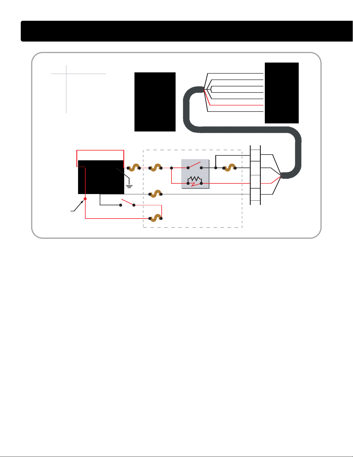
ECM Relay Circuit Operation
• The ECM controls its own power up
and power down process. When
the key is OFF, the ECM stays
powered up for a brief period. The
ECM then powers down after
internal housekeeping functions
have been completed.
Key Power
• The Run/Accessory position of the
key switc
h receives battery voltage
from the Power Distribution Center
(PDC) fuse F-12. When the key is
ON, the switch supplies battery
voltage through fuse F46 to ECM
pin X3-3. Battery voltage is
available at all times through fuses
F4 and F41 to ECM relay pins 1
and 3. The two fuses are in series,
with F4 feeding both the IDM and
ECM relays, and F41 dedicated to
protecting the ECM circuit alone.
Pin 1 supplies voltage to the
relay coil.
• Pin 2 connects the coil to pin X3-5
of the ECM.
• When the key is ON, voltage
supplied to pin X3-3 signals the
ECM that the operator is going to
start the engine. The ECM then
supplies a ground circuit to pin X3-5.
When this occurs, current flows
through the ECM relay coil and
creates a magnetic field causing
the relay to latch. When latched, the
relay connects pin 3 to pin 5 and
supplies current to the ECM
through pin X4-1 and X4-2.
International®VT 275 V6 Engine
Shut Down
• When the key is OFF and volt
removed from ECM pin X3-3, the
ECM shuts down the engine but
keeps the ECM powered up briefly
until the internal house keeping is
completed.
age is
27
ECM
BATT ER
Y
200 A F4
F-46
TO IDM RELAY
F-12
R
PDC
F40
2
IDM
STAR TER
MOTOR
RELAY
KEY SWITCH
PDC#
F4
F12
F40
F46
R
Device
30A...IDM/ECM
20A...RUN/ACC
10A...IDM LOGIC
5A...ECM KEY PWR
IDM RELAY - POSITION 55
X1
X2
X3
X1
X2
X3
X3-8 IDM LOGIC POWER
X3-24 IDM M AIN POWER
X3-25 IDM MAIN POWER
X3-4 IDM M AIN POWER
X3-23 IDM M AIN POWER
X3-27 IDM M PR
X3-7 V
IGN
12
6
8
9
ENGINE IN-LINE
12-WAY
30 87
85 86
2
X1
X2
X3
X4
X1
X2
X3
X4
ELECTRONIC CONTROL SYSTEM
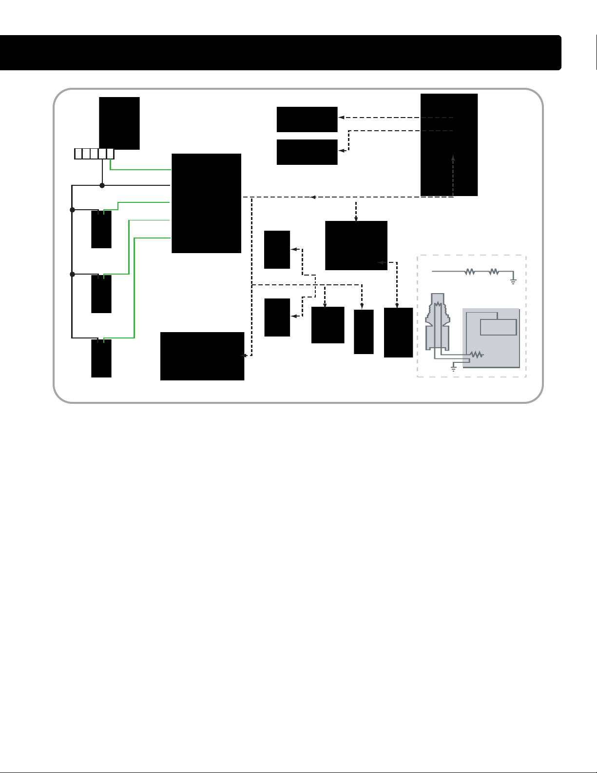
IDM Relay Circuit Operation
• The IDM controls its own power up
and power down process. When
the key is OFF, the IDM stays
powered up for a brief period. The
IDM then powers down after
internal housekeeping functions
have been completed.
IDM Power Up
• The key switch receives battery
age from the Power Distribution
volt
Center (PDC) F-12 fuse. When the
key is ON, the switch supplies
battery voltage through F-46 fuse
and pin 9 of the engine 12-way
connector to pin X3-7 of the IDM.
• Battery voltage is available through
the PDC F-4 fuse to IDM relay pin
30 and 85 at all times. Pin 85
supplies voltage to the relay coil.
Pin 86 takes that voltage through
pin 8 of the engine 12-way
connector to pin X3-27 of the IDM.
When the key is ON, voltage
supplied to pin X3-7 signals the
IDM to provide a ground circuit to
pin X3-27. When this occurs,
current flowing through the IDM
relay coil builds a magnetic field
that causes the relay to latch. When
latched, the relay connects pin 30
to pin 87 and supplies current
through pin 12 of the engine in-line
12-way connector to pin X3-4, X323, X3-24, and X3-25 of the IDM.
Four pins receive voltage to spread
the current draw over multiple pins.
IDM Logic
• The IDM also requires volt
age for
the internal logic circuit. When the
IDM relay latches, pin 87 of the relay
supplies voltage to the IDM logic
circuit through the F-40 fuse in the
PDC. The F-40 fuse feeds through
pin 6 of the engine in-line 12-way
connector to the IDM pin X3-8.
28
International®VT 275 V6 Engine
ELECTRONIC CONTROL SYSTEM
ECM
VOLTAGE
RR
SENSOR
IDM
ECM
X1
X2
X3
X4
E DC BA
IAT
X1-7 IAT
X1-6 GRD
X1-8 ECT
X2-1 EOT
X2-14 MAT
MAF / IAT
EGR
DRIVE
MODULE
IAH RELAY
GLOW PLUG
RELAY
BCS
IPR
EGR
VALVE
ECT
EOT
MAT
RIGHT BANK INJECTORS
LEFT BANK I NJECTORS
REFERENCE
VOLTAGE
MICROPROCESSOR
R
R
1
1
2
2
X1
X2
X3
X1
X2
X3
Temperature Sensor Operation
• There are four, two-wire temperature sensors on the VT 275
engine. Each sensor contains a
resistor whose value varies depending on temperature. The ECM
supplies a separate reference
voltage to each temperature sensor.
Then, the sensor conditions its
voltage to produce the sensor signal.
Sensor Circuit
• A temperature variable resistor is a
thermistor
connected to a current-limiting
resistor of fixed value within the
. Each thermistor is
ECM. The thermistor and the
resistor make a series circuit with a
reference voltage applied at one
end and a ground at the other. The
voltage in the circuit between the
two resistors changes as the
thermistor's resistance changes.
When the temperature is low, the
sensor's resistance is high and the
signal voltage is high. When the
temperature is high, the resistance
is low and the signal voltage is low.
Engine Coolant Temperature
(E
CT) Sensor
• The ECT sensor is mounted in the
front cover. The body of the sensor
is exposed to coolant as it returns
from the cylinder heads. The ECT
signal is input into the optional
engine warning protection system,
coolant compensation, glow plug
operation and the instrument
cluster temperature gauge.
Engine Oil Temperature
OT) Sensor
(E
• The EO
oil filter adapter. The EOT signal
allows the ECM to compensate for
viscosity changes in the oil due to
temperature. The EOT signal is
input into calculations that
determine the fuel quantity and timing.
T sensor is mounted in the
International®VT 275 V6 Engine
Manifold Air Temperature
(MAT) Sensor
• The MAT sensor is mounted
towards the front of the left bank leg
of the intake manifold. T
sensor measures the temperature
of the air in the intake manifold. The
ECM uses this information in
calculations that control the EGR
valve operation.
Intake Air Temperature
T) Sensor
(IA
• The IAT sensor is contained within
the Mass Air Flow (MAF) sensor
housing. The MAF sensor is
mounted to the inlet duct leading to
the turbocharger. The ECM uses
the IAT information to control
injection timing and fuel rate when
starting cold.
he MAT
29
ECM
IDM
ECM
X1
X2
X3
X4
EGR
DRIVE
MODULE
BCS
IPR
EGR
VALVE
EOPS
ICP
MAP
RIGHT BANK INJECTORS
LEFT BANK I NJECTORS
REFERENCE
VOLTAGE
MICROPROCESSOR
SWITCH
Functional Equivelant
X1-6 GRD
X1-13 EOPS
X1-14 V
REF
X1-20 ICP
X2-3 MAP
X1
X2
X3
X1
X2
X3
VREF
SENSOR
ELECTRONIC CONTROL SYSTEM
Pressure Sensor Operation
• The Manifold Absolute Pressure
(MAP) sensor, the Injection Control
Pressure (ICP) sensor and the
Engine Oil Pressure Switch
(EOPS) are used to send pressure
information to the ECM.
• The MAP and ICP are three-wire
pressure sensors. Three-wire
pressure sensors receive a
reference voltage and a ground
from the ECM. The sensor returns a
portion of the reference voltage,
proportional to the pressure, back
to the ECM as a signal.
Injection Control Pressure
(ICP) Sensor
• The ICP sensor is a Micro Strain
Gauge (M
MSG type sensor has a small strain
gauge that senses changes in
pressure. Sensor mounted
electronic circuitry converts the
30
SG) style sensor. The
• T
change into a signal voltage
proportional to the pressure being
measured. The ICP sensor is used
to make corrections to the IPR
signal and to continually check the
performance of the Injection
Control Pressure system.
Manifold Absolute Pressure
(MAP) sensor
he MAP sensor is a variable
capacitance style sensor. In a
variable capacitance sensor, the
pressure being measured deflects a
ceramic disk towards a metal disk.
The two materials make up a
variable capacitor. Sensor mounted
circuitry converts the capacitance
into a signal voltage proportional to
the measured pressure. The MAP
sensor measures turbocharger
boost in the intake manifold. The
MAP signal is input into calculations
that determine fueling quantities
and the desired EGR valve position.
International®VT 275 V6 Engine
Engine Oil Pressure Switch
(EOPS)
• The EOPS is used to detect oil
pressure and is an input to the dash
cluster and the engine warning
protection system. T
he switch is
normally open with the engine off
but closes when oil pressure
reaches 5 to 7 psi. The ECM sends
5 volts through a current limiting
resistor to the EOPS and reads the
voltage between the resistor and
the switch. When oil pressure is
low, the switch is open and the
ECM reads 5 volts.
When the oil pressure is greater
than 5 to 7 psi, the switch is closed,
the circuit is shorted to ground, and
the ECM reads a low voltage.
When the ECM detects oil pressure, MasterDiagnostics
®
will display
40 psi. When the oil pressure is
below 5 psi, MasterDiagnostics
will display 0 psi.
®
 Loading...