


 Loading...
®
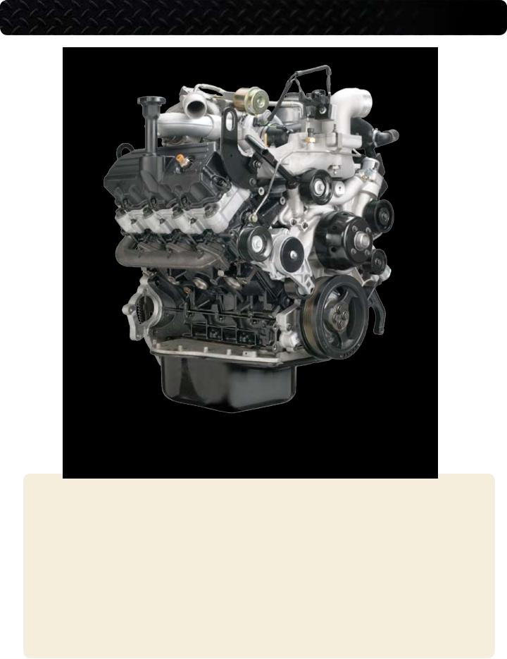
VT 275 V6 ENGINE
model year 2006
FEATURES AND DESCRIPTIONS FOR WORKHORSE CUSTOM CHASSIS APPLICATIONS
TM
FORWARD
This publication is intended to provide technicians and service personnel with an overview of the technical features of the International® VT 275 Diesel Engine. The information contained in this publication is a supplement to information that is contained in available service literature. The photos and illustrations in this publication may vary from your particular vehicle. Consult the latest SERVICE and DIAGNOSTIC manuals for the latest information, before you conduct any service or repairs.
|
International® VT 275 V6 Engine • Workhorse Chassis Applications • Revision 1.0 • © Copyright 2006 International Truck and Engine Corporation |

Safety Information
This manual provides general and specific service procedures and repair methods essential for your safety and the reliable operation of the engine. Since many variations in tools, procedures, and service parts are involved, advice for all of the possible safety conditions and hazards cannot be stated.
Departure from the instructions in this manual or disregard of warnings and cautions can lead to injury, death, or both, and damage to the engine or vehicle.
Read the safety instructions below before doing service and test procedures in this manual for the engine or vehicle. See related application manuals for more information.
Safety Instructions
Vehicle
Make sure the vehicle is in neutral, the parking brake is set, and the wheels are blocked before you perform any work or diagnostic procedures on the engine or vehicle.
Fire Prevention
NOTE: Check the classification of each fire extinguisher to ensure that the following fire types can be extinguished:
1.Type A - Wood, paper, textiles, and rubbish
2.Type B - Flammable liquids
3.Type C - Electrical equipment
•Make sure that charged fire extinguishers are in the work area.
Batteries
•Batteries produce highly flammable gas during and after charging.
•Always disconnect the main negative battery cable first.
•Always connect the main negative battery cable last.
•Avoid leaning over batteries.
•Protect your eyes.
•Do not expose batteries to open flames or sparks.
•Do not smoke in workplace.
Work Area
•Keep the work area clean, dry and organized.
•Keep tools and parts off the floor.
•Make sure the work area is ventilated and well lit.
•Make sure a First Aid Kit is available.
Safety Equipment
•Use the correct lifting devices.
•Use the proper safety blocks and stands.
Protective Measures
•Wear protective glasses and safety shoes (do not work in bare feet, sandals, or sneakers).
•Wear the appropriate hearing protection.
•Wear the correct clothing.
•Do not wear rings, watches, or other jewelry.
•Restrain long hair.
Compressed Air
•Limit shop air pressure for blow gun to 207 kPa (30psi).
•Use approved equipment.
•Do not direct air at body or clothing.
•Wear safety glasses or goggles.
•Wear hearing protection.
•Use shielding to protect others in the work area.
Fluids Under Pressure
•Use extreme caution when working on systems under pressure.
•Follow approved procedures only.
Fuel
•Do not over fill fuel tank. Over fill creates a fire hazard.
•Do not smoke in the work area.
•Do not refuel the tank when the engine is running.
Tools
•Make sure all tools are in good condition.
•Make sure all standard electrical tools are grounded.
•Check for frayed power cords before using power tools.
Removal of Tools, Parts, and Equipment
•Reinstall all safety guards, shields and covers after servicing the engine.
•Make sure all tools, parts, and service equipment are removed from the engine and vehicle after all work is done.
International® VT 275 V6 Engine • Workhorse Chassis Applications • Revision 1.0 • © Copyright 2006 International Truck and Engine Corporation |
|

TABLE OF CONTENTS
DESIGN FEATURES . . . . . . . . . . . . . . . . . . . . . . . . . . . . . . . . . . . . . . . . . . . . . . . 5 OVERVIEW . . . . . . . . . . . . . . . . . . . . . . . . . . . . . . . . . . . . . . . . . . . . . . . . . . . . . . 6 COMPONENT LOCATIONS . . . . . . . . . . . . . . . . . . . . . . . . . . . . . . . . . . . . . . . . . . . 8 ELECTRONIC CONTROL SYSTEM . . . . . . . . . . . . . . . . . . . . . . . . . . . . . . . . . . . . 18 AIR MANAGEMENT SYSTEM . . . . . . . . . . . . . . . . . . . . . . . . . . . . . . . . . . . . . . . 42 FUEL SUPPLY SYSTEM . . . . . . . . . . . . . . . . . . . . . . . . . . . . . . . . . . . . . . . . . . . . 44 LUBRICATION SYSTEM . . . . . . . . . . . . . . . . . . . . . . . . . . . . . . . . . . . . . . . . . . . . 48 COOLING SYSTEM . . . . . . . . . . . . . . . . . . . . . . . . . . . . . . . . . . . . . . . . . . . . . . . 50 SPECIAL TOOLS . . . . . . . . . . . . . . . . . . . . . . . . . . . . . . . . . . . . . . . . . . . . . . . . . 52 HARD START / NO START and PERFORMANACE DIAGNOSTICS . . . . . . . . . . . . . . 53 DIAGNOSTIC TROUBLE CODES . . . . . . . . . . . . . . . . . . . . . . . . . . . . . . . . . . . . . 66 POWER DISTRIBUTION CENTER . . . . . . . . . . . . . . . . . . . . . . . . . . . . . . . . . . . 71 ENGINE & CHASSIS SCHEMATIC . . . . . . . . . . . . . . . . . . . . . . . . . . . . . . . . . . . 72 GLOSSARY . . . . . . . . . . . . . . . . . . . . . . . . . . . . . . . . . . . . . . . . . . . . . . . . . . . . . 74
|
International® VT 275 V6 Engine • Workhorse Chassis Applications • Revision 1.0 • © Copyright 2006 International Truck and Engine Corporation |
DIRECT INJECTION TURBOCHARGED DIESEL ENGINE
VT 275 FEATURES
•90° V6
•Offset Crankpins
•Rear Gear Train
•Primary Balancer
•Regulated Two-Stage Turbocharging System
•Four Valves per Cylinder
•Cooled Exhaust Gas Recirculation
•Electro-Hydraulic Generation 2 Fuel Injection System
•Top Mounted Oil and Fuel Filters
International® VT 275 V6 Engine • Workhorse Chassis Applications • Revision 1.0 • © Copyright 2006 International Truck and Engine Corporation |
|
VT 275 0VERVIEW
VT 275 ENGINE SPECIFICATIONS
Engine Type . . . . . . . . . . . . . . . . . . . . . . . . . . . . . . . . . . . . . . . . 4-stroke, direct injection diesel Configuration . . . . . . . . . . . . . . . . . . . . . . . . . . . . . V6, pushrod operated four valves / cylinder Displacement . . . . . . . . . . . . . . . . . . . . . . . . . . . . . . . . . . . . . . . . . . . . . . . 275 cu. in. (4.5 liters) Bore . . . . . . . . . . . . . . . . . . . . . . . . . . . . . . . . . . . . . . . . . . . . . . . . . . . . . . . . . . 3.74 in. (95 mm) Stroke . . . . . . . . . . . . . . . . . . . . . . . . . . . . . . . . . . . . . . . . . . . . . . . . . . . . . . 4.134 in. (105 mm) Compression Ratio . . . . . . . . . . . . . . . . . . . . . . . . . . . . . . . . . . . . . . . . . . . . . . . . . . . . . . . 18.0:1 Aspiration . . . . . . . . . . . . . . . . . . . . . . . . . . . . . . . . . Twin turbocharged and charge air cooled Rated Power . . . . . . . . . . . . . . . . . . . . . . . . . . . . . . . . . . . . . . . . . . . . . . . . 200 hp @ 2700 rpm Peak Torque . . . . . . . . . . . . . . . . . . . . . . . . . . . . . . . . . . . . . . . . . . . . . . . 440 lb-ft @ 1800 rpm Engine Rotation, Facing the Flywheel . . . . . . . . . . . . . . . . . . . . . . . . . . . . . . Counterclockwise Injection System . . . . . . . . . . . . . . . . . . . . . . . . . . Electro-hydraulic generation 2 fuel injection Cooling Sysytem Capacity (Engine Only) . . . . . . . . . . . . . . . . . . . . . . . . . . . . . . . . . . 11 quarts Lube System Capacity (Engine Only) . . . . . . . . . . . . . . . . . . . . . . . . . . 15 quarts with oil filter
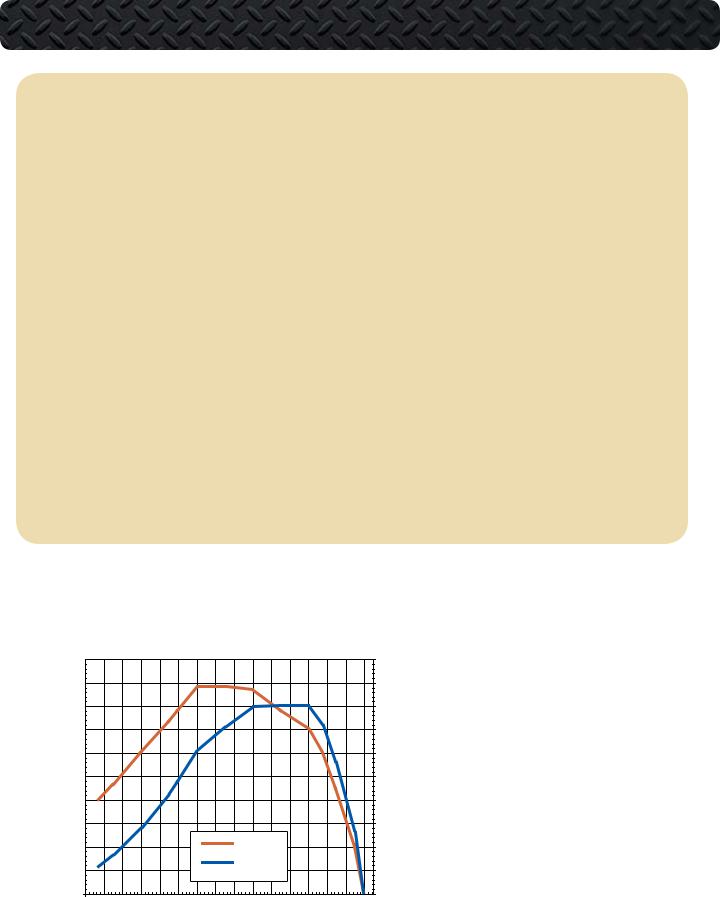
Power & Torque Curve
|
500 |
|
|
|
|
|
|
|
|
|
|
|
|
|
|
250 |
|
|
450 |
|
|
|
|
|
|
|
|
|
|
|
|
|
|
225 |
|
|
400 |
|
|
|
|
|
|
|
|
|
|
|
|
|
|
200 |
|
|
350 |
|
|
|
|
|
|
|
|
|
|
|
|
|
|
175 |
|
(ft-lb) |
300 |
|
|
|
|
|
|
|
|
|
|
|
|
|
|
150 |
Power |
250 |
|
|
|
|
|
|
|
|
|
|
|
|
|
|
125 |
||
Load |
200 |
|
|
|
|
|
|
|
|
|
|
|
|
|
|
100 |
(HP) |
|
150 |
|
|
|
|
|
|
|
|
|
|
|
|
|
|
75 |
|
|
100 |
|
|
|
|
|
|
|
Torque (ft-lb) |
|
|
|
|
50 |
|
||
|
|
|
|
|
|
|
|
|
|
|
|
|
|
|
|
||
|
50 |
|
|
|
|
|
|
|
Power (HP) |
|
|
|
|
25 |
|
||
|
|
|
|
|
|
|
|
|
|
|
|
|
|
|
|
||
|
0 |
|
|
|
|
|
|
|
|
|
|
|
|
|
|
0 |
|
|
600 |
800 |
1000 |
1200 |
1400 |
1600 |
1800 |
2000 |
2200 |
2400 |
2600 |
2800 |
3000 |
3200 |
3400 |
3600 |
|
Horsepower and Torque
The VT 275 engine is offered with only one horsepower and torque rating for the 2005 model year. The engine creates 200 horsepower at 2700 rpm and 440 lb-ft of torque at 1800 rpm. The engine has a high idle speed of 2775 rpm with automatic transmission. The engine idle speed is set at 700 rpm and is not adjustable.
Engine Speed (RPM)
|
International® VT 275 V6 Engine • Workhorse Chassis Applications • Revision 1.0 • © Copyright 2006 International Truck and Engine Corporation |
VT 275 OVERVIEW
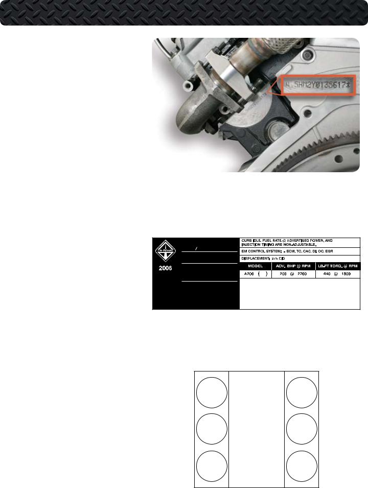
Engine Serial Number
The Engine Serial Number (ESN) for the VT 275 is located on a machined surface at the left rear corner of the crankcase just below the cylinder head.
The ESN identifies the engine family, the build location, and the sequential
build number.
Engine Serial Number Example:
4.5HM2Y0135617
4.5 = Engine displacement H = Diesel, Turbocharged M2 = Motor Truck
Y = Huntsville
0135617 = Build Sequence
Emissions Label
The Environmental Protection Agency (EPA) emissions label is on top of the breather, toward the front, on the left valve cover. The label includes the following:
•Advertised horsepower rating
•Engine model code
•Service application
•Emission family and control system
•Year the engine was certified to meet EPA emission standards
VT 275 ENGINE FAMILY 6NVXH0275AEA
EMISSION CONTROL
TM INFORMATION
ENGINE MANUFACTURED BY:
INTERNATIONAL TRUCK
AND ENGINE CORPORATION
INTERNATIONAL 1870616C1
THIS ENGINE HAS A PRIMARY INTENDED SERVICE APPLICATION AS A LIGHT HEAVY-DUTY DIESEL ENGINE AND CONFORMS TO U.S. EPA , CANADIAN, AND AUSTRALIAN ADR-30 2006 MODEL YEAR REGULATIONS. THE ENGINE IS ALSO CERTIFIED FOR SALE IN CALIFORNIA IN NEW VEHICLES RATED ABOVE
14,000 POUNDS GVWR AND IS CERTIFIED TO OPERATE ON DIESEL FUEL. THIS ENGINE IS OBD II EXEMPT.
Cylinder Numbering
The cylinders on the VT 275 are numbered from the front of the right bank 1, 3, 5 and from the front of the left bank 2, 4 and 6.
The engine firing order is 1-2-5-6-3-4
L Front R
2 1
4 3
6 5
International® VT 275 V6 Engine • Workhorse Chassis Applications • Revision 1.0 • © Copyright 2006 International Truck and Engine Corporation
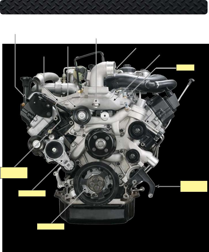
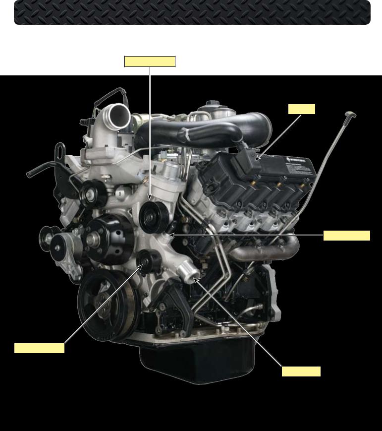
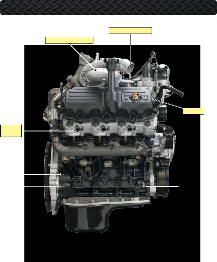
COMPONENT LOCATIONS - FRONT OF ENGINE
HEATER SUPPLY TUBE |
|
|
|
|
AIR INLET HEATER |
|
|
||
|
|
|
|
|
|
|
|
|
|
|
|
|
SMOOTH IDLER PULLEY |
|
|
|
AIR INLET |
|
|
|
|
|
|
|
|
|
|
|
|
|
FUEL TUBE TO RIGHT BANK |
|
|
|
|
|
INTAKE MANIFOLD |
||
MAT SENSOR
BANJO BOLT WITH
CHECK VALVE
POWER STEERING
PUMP BRACKET
BELT TENSIONER
OIL PUMP COVER
|
International® VT 275 V6 Engine • Workhorse Chassis Applications • Revision 1.0 • © Copyright 2006 International Truck and Engine Corporation |
COMPONENT LOCATIONS - LEFT FRONT OF ENGINE
GROOVED IDLER PULLEY
BREATHER
HEATER RETURN TUBE
SMOOTH IDLER PULLEY
COOLANT OUTLET
International® VT 275 V6 Engine • Workhorse Chassis Applications • Revision 1.0 • © Copyright 2006 International Truck and Engine Corporation |
|
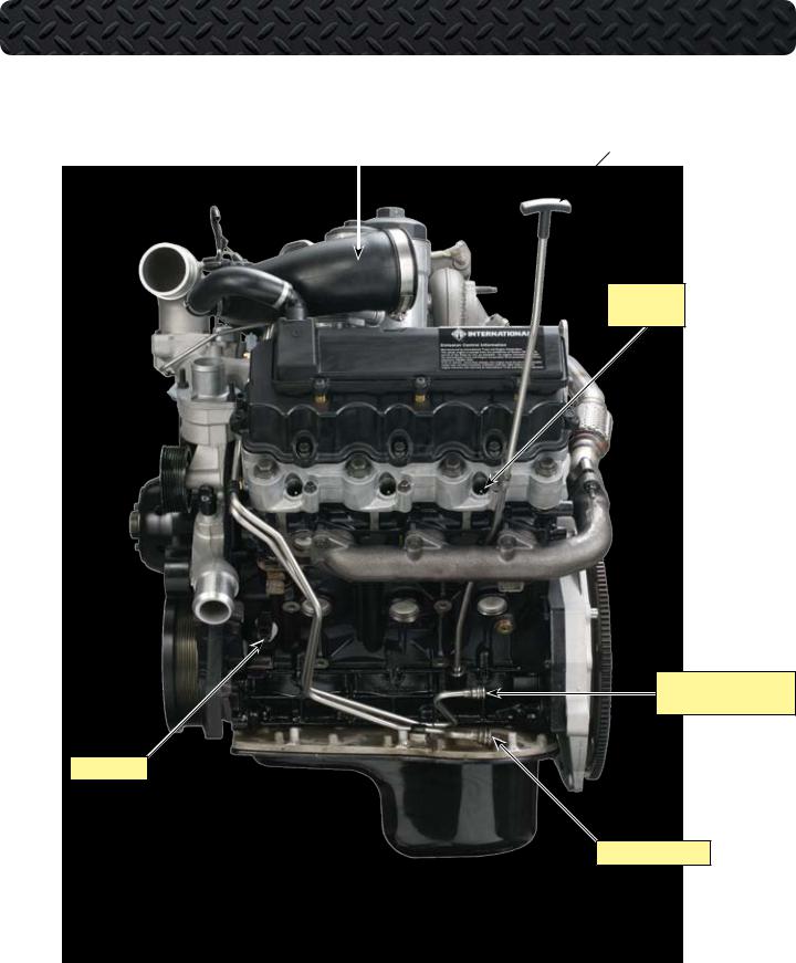
COMPONENT LOCATIONS - LEFT SIDE OF ENGINE
AIR INLET DUCT |
|
OIL LEVEL GAUGE |
|
|
|
|
|
LEFT BANK
GLOW PLUGS
SUPPLY FROM FUEL PUMP
AND PRIMARY FILTER
CMP SENSOR
FUEL RETURN TO TANK
10 |
International® VT 275 V6 Engine • Workhorse Chassis Applications • Revision 1.0 • © Copyright 2006 International Truck and Engine Corporation |
COMPONENT LOCATIONS - LEFT REAR OF ENGINE
LIFTING EYES
IPR AND
HEAT SHIELD
LEFT BANK
EXHAUST MANIFOLD
REAR COVER
International® VT 275 V6 Engine • Workhorse Chassis Applications • Revision 1.0 • © Copyright 2006 International Truck and Engine Corporation |
11 |
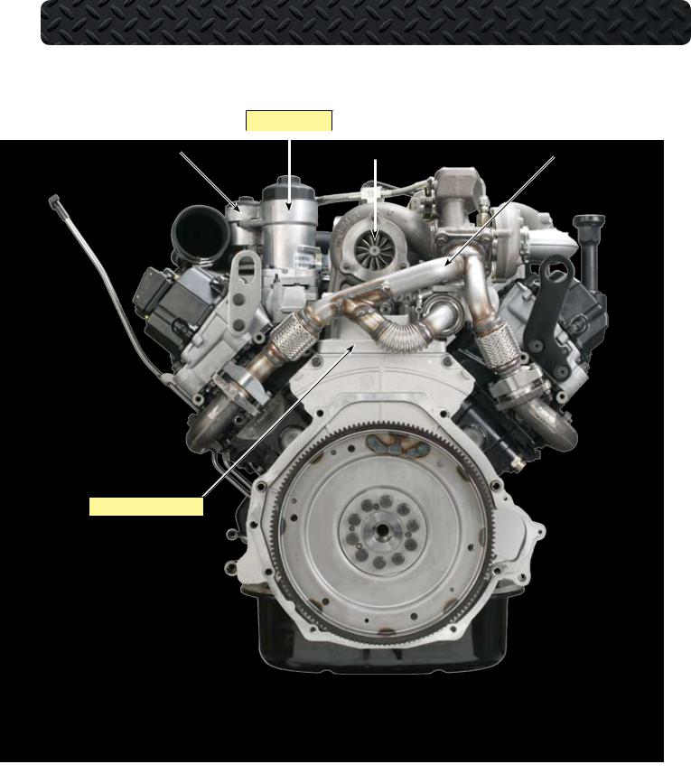
COMPONENT LOCATIONS - REAR OF ENGINE
OIL FILTER HOUSING
|
|
|
|
|
|
|
|
|
FUEL FILTER HOUSING |
|
|
|
|
TURBINE HOUSING |
|
EXHAUST TUBE ASSEMBLY |
|
|
|
|
|
|
|
|
|
|
|
|
|
|
|
|
|
|
|
HIGH PRESSURE PUMP COVER
12 |
International® VT 275 V6 Engine • Workhorse Chassis Applications • Revision 1.0 • © Copyright 2006 International Truck and Engine Corporation |
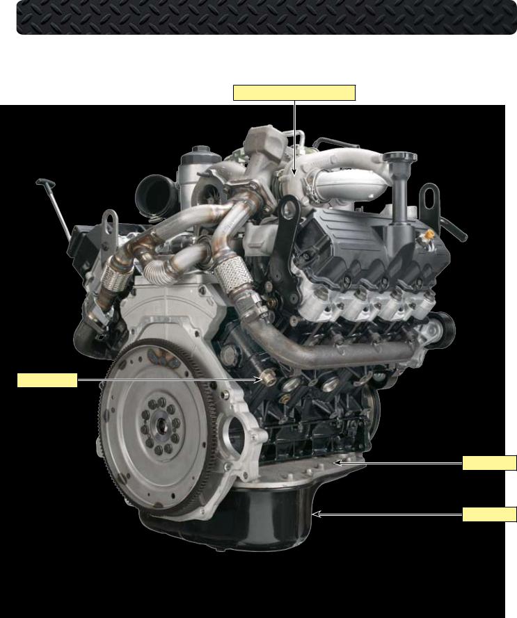
COMPONENT LOCATIONS - RIGHT REAR OF ENGINE
HIGH PRESSURE COMPRESSOR HOUSING
COOLANT HEATER
UPPER OIL PAN
LOWER OIL PAN
International® VT 275 V6 Engine • Workhorse Chassis Applications • Revision 1.0 • © Copyright 2006 International Truck and Engine Corporation |
13 |
COMPONENT LOCATIONS - RIGHT SIDE OF ENGINE
OUTLET TO CHARGE AIR COOLER
TURBOCHARGER CROSSOVER TUBE
ICP SENSOR
RIGHT BANK
GLOW PLUGS
CRANKCASE |
|
|
|
|
|
|
|
|
|
||
|
|
|
|
||
LOWER |
|
|
|
||
|
CKP SENSOR |
||||
CRANKCASE |
|
|
|
||
|
|
|
|||
|
|
|
|||
|
|
|
|
|
|
14 |
International® VT 275 V6 Engine • Workhorse Chassis Applications • Revision 1.0 • © Copyright 2006 International Truck and Engine Corporation |
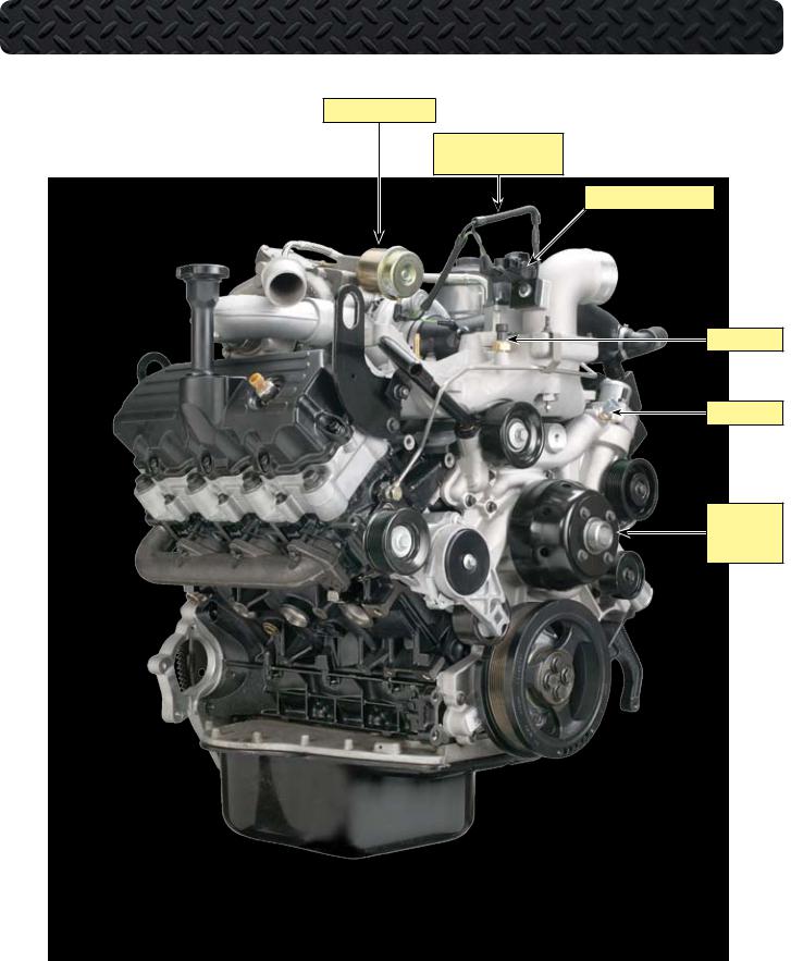
COMPONENT LOCATIONS - RIGHT FRONT OF ENGINE
PNEUMATIC ACTUATOR
BOOST CONTROL SOLENOID
HOSE HARNESS
BOOST CONTROL SOLENOID
MAP SENSOR
ECT SENSOR
WATER PUMP
PULLEY
AND FAN DRIVE
International® VT 275 V6 Engine • Workhorse Chassis Applications • Revision 1.0 • © Copyright 2006 International Truck and Engine Corporation |
15 |
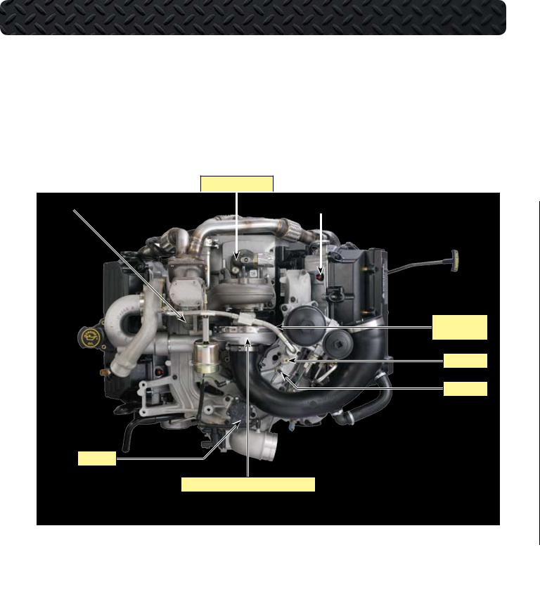
COMPONENT LOCATIONS - TOP OF ENGINE WITHOUT HARNESS
HIGH PRESSURE PUMP
|
|
|
|
|
|
|
HIGH PRESSURE TURBINE HOUSING |
|
|
|
|
INJECTOR CONNECTORS |
|
|
|
|
|
|
|
|
|
|
|
|
|
|
|
TURBOCHARGER
OIL SUPPLY LINE
EOP SWITCH
EOP SENSOR
EGR VALVE
LOW PRESSURE TURBO COMPRESSOR HOUSING
16 |
International® VT 275 V6 Engine • Workhorse Chassis Applications • Revision 1.0 • © Copyright 2006 International Truck and Engine Corporation |
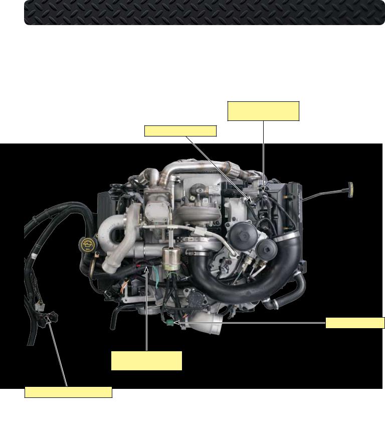
COMPONENT LOCATIONS - TOP OF ENGINE WITH HARNESS
MAF SENSOR CONNECTOR (SENSOR NOT SHOWN)
INJECTOR HARNESS CONNECTOR
BOOST CONTROL SOLENOID
ALTERNATOR FUSIBLE LINKS (ALTERNATOR NOT SHOWN)
HARNESS TO CHASSIS-MOUNTED ECM/IDM
International® VT 275 V6 Engine • Workhorse Chassis Applications • Revision 1.0 • © Copyright 2006 International Truck and Engine Corporation |
17 |
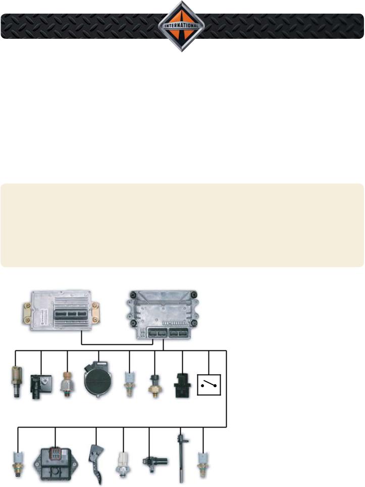
ELECTRONIC CONTROL
SYSTEM
•ECM and IDM control system
•Dual magnetic pick-up timing sensors
•Electric motor driven EGR valve
•ECM boost control
IDM |
ECM |
System Features
IPR |
BCS |
ICP |
MAF / IAT |
ECT |
MAP |
BAP |
ECL |
MAT |
EGR DRIVE |
APS / IVS |
EOP |
CKP |
CMP |
EOT |
MODULE |
•The VT 275 engine uses the Diamond Logic™ II Control System. The electronic control system features an Engine Control Module (ECM)
and an Injector Drive Module (IDM).
•The Exhaust Gas Recirculation (EGR) valve is positioned by an ECM controlled electric stepper motor. The system uses an EGR drive module to communicate commands
from the ECM to the EGR valve.
•VT 275 engines use two magnetic pickup sensors to determine crankshaft speed and position and camshaft position. Magnetic pick-up sensors
feature high reliability and accuracy.
•The VT 275 engine uses a twin turbocharger with ECM boost control.
18 |
International® VT 275 V6 Engine • Workhorse Chassis Applications • Revision 1.0 • © Copyright 2006 International Truck and Engine Corporation |
ELECTRONIC CONTROL SYSTEM
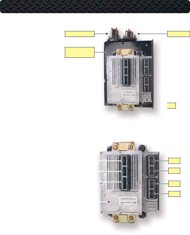
ECM
•The ECM uses sensor inputs to control the Injection Pressure Regulator (IPR), the EGR valve, the boost control solenoid, the glow plug relay and the inlet air heater relay. The ECM also shares sensor data with the IDM over communication links between the two modules.
•The IDM is mounted on brackets cast into the ECM. The ECM and IDM are then mounted with vibration isolator grommets to the control module assembly bracket on the Power Distribution Center (PDC).
INLET AIR HEATER RELAY
CONTROL MODULE ASSEMBLY BRACKET
IDM
•The Injector Drive Module (IDM) receives sensor information from the ECM over three communication links: the CAN 2 link, the CMPO circuit, and the CKPO circuit. The IDM uses this information to calculate injection timing and duration. The IDM controls injector operation through 48-
volt signals to the twin injector coils. |
IDM X1 |
|
|
|
|
||
• The ECM has four connectors. The |
|
|
|
IDM X2 |
|
|
|
connectors are called X1 through X4 |
|
|
|
|
|
||
with ECM X1 being the top ECM con- |
|
|
|
nector as mounted on the truck. The |
IDM X3 |
|
|
|
|
||
IDM has three connectors with IDM X1 |
|
|
|
|
|
|
|
being the top connector as mounted |
|
|
|
on the truck. The ECM X1 and X2 con- |
|
|
|
nectors are for engine sensor inputs |
|
|
|
and X3 and X4 are for chassis inputs. |
IDM |
|
|
|
|
||
The IDM X1 and X2 connectors are for |
|
|
|
injector operation and X3 is for chassis |
|
|
|
inputs and communication between |
|
|
|
the ECM and IDM. |
|
|
|
GLOW PLUG RELAY
 ECM
ECM
ECM X1
ECM X2
ECM X3
ECM X4
International® VT 275 V6 Engine • Workhorse Chassis Applications • Revision 1.0 • © Copyright 2006 International Truck and Engine Corporation |
19 |
ELECTRONIC CONTROL SYSTEM
|
|
EGR Drive Module |
|
|
• The EGR Drive Module receives the desired |
|
|
EGR valve position from the ECM over the en- |
|
|
gine CAN 2 link. The module then sends a series |
|
|
of voltage and ground signals to the Motor U, V, |
|
|
and W terminals of the EGR valve. The voltage |
|
|
signals are Pulse Width Modulated (PWM) |
|
|
to control current flow to the motor field coils. |
|
|
• The module receives battery voltage and ground |
EGR DRIVE MODULE |
|
|
|
||
|
through the 12-way engine-to-chassis connec- |
|
|
|
|
|
|
tor. The module supplies a reference voltage to |
|
|
three position sensors within the EGR valve. |
|
|
The drive module uses the sensor signals to |
|
|
determine the percent of valve opening. |
|
|
|
|
Inlet Air Heater Element |
|
|
|
|
• The Inlet Air Heater element is located in the |
|
|
|
INTAKE MANIFOLD |
|
|
|
|
lower side of the intake manifold and projects |
|
|
|
|
|
|
|
|
|
|
through the manifold and into the inlet air stream. |
|
|
|
|
• The element warms the incoming air to aid |
|
|
|
|
cold start and reduce emissions during warm- |
|
|
|
|
up. The ECM turns the inlet air heater on for |
|
|
|
|
a predetermined amount of time, based on |
|
|
|
|
engine oil temperature, intake air temperature, |
|
|
|
|
and barometric air pressure. The inlet air heater |
|
|
|
|
can remain on while the engine is running to |
INLET AIR HEATER |
|
|
|
reduce white smoke during engine warm-up. |
|
|
|
|
|
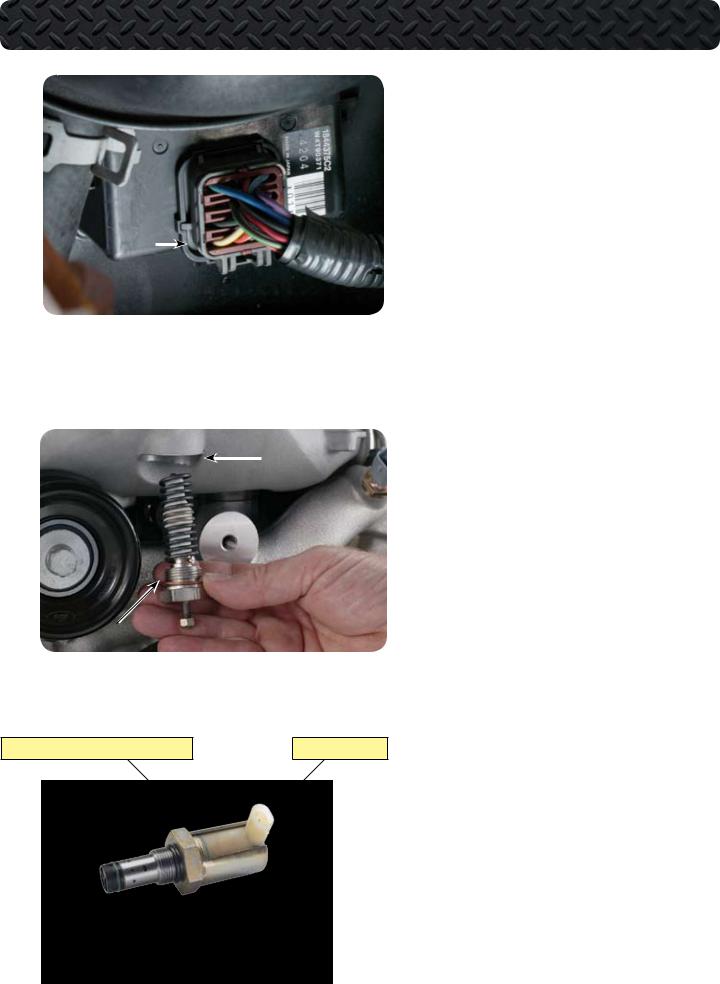
Injection Pressure Regulator (IPR) Valve
INJECTION PRESSURE REGULATOR (IPR) VALVE |
SWIVEL CONNECTOR |
• The IPR mounts to the high-pressure pump and controls the amount of oil allowed to drain from the high-pressure system. When the ECM increases the IPR signal duty cycle, the valve blocks the oil’s path to drain and pressure rises. When the ECM reduces the duty cycle, a larger volume of oil is allowed to drain from the system and pressure is reduced. The valve contains a pressure relief valve for the system that opens if system pressure reaches 4500 psi. The IPR is protected by a heat shield that must be reinstalled after servicing.
20 |
International® VT 275 V6 Engine • Workhorse Chassis Applications • Revision 1.0 • © Copyright 2006 International Truck and Engine Corporation |
ELECTRONIC CONTROL SYSTEM
Inlet Air Heater Relay
•The Inlet Air Heater (IAH) element is used to improve cold start operation, reduce emissions and white smoke, and improve engine warm-up. The IAH relay is the taller of the two relays. The IAH relay receives battery power from the starter power-feed terminal and the normally open terminal connects to the element through the harness. One end of the relay coil is grounded through the engine 12-way connector. The relay closes when the coil receives voltage from the ECM.
Glow Plug Relay
•Glow plugs are used to improve cold engine starting. Glow plug operation is controlled by the ECM through the glow plug relay. The relay common terminal is connected by jumper to the common terminal of the Inlet Air Heater relay. The normally open terminal connects to the glow plug harness. One end of the relay coil is grounded through the engine 12-way connector. The relay is closed when the other end of the coil receives voltage from the ECM.
AIR HEATER RELAY
GLOW PLUG RELAY
MAF / IAT
5-PIN
CONNECTOR
Mass Air Flow (MAF) Sensor
MASS AIR FLOW (MAF) SENSOR
•The Mass Air Flow (MAF) sensor is mounted with ductwork between the turbocharger inlet and the air filter element. The sensor applies voltage to a low resistance thermistor exposed to the fresh air portion of the intake charge. The MAF sensor circuitry measures the increase in voltage required to offset the cooling effect of the air flow over the thermistor. This voltage is then converted into a variable frequency that is sent to the ECM. The MAF value can be read with MasterDiagnostics® software in lb./min.
International® VT 275 V6 Engine • Workhorse Chassis Applications • Revision 1.0 • © Copyright 2006 International Truck and Engine Corporation |
21 |
ELECTRONIC CONTROL SYSTEM
PDC# |
Device |
F4 |
30A...IDM/ECM |
F12 |
20A...RUN/ACC |
F41 |
10A...ECM PWR |
F46 |
5A...ECM KEY PWR |
R1 |
ECM RELAY - POSITION 50 |
|
|
ECM |
X1 |
X3-3 |
VIGN |
|
|
||
|
X2 |
X3-5 |
ECM MPR |
|
X3 |
X4-1 |
ECM PWR |
|
X4 |
X4-2 |
ECM PWR |
|
|
PDC
TO IDM RELAY |
TO |
|
|
INL |
F38 |
12 |
R1 |
|
30 |
87 |
BATTERY |
|
86 |
85 |
F-47 |
|
STARTER |
|
MOTOR |
|
RELAY |
|
KEY SWITCH |
|
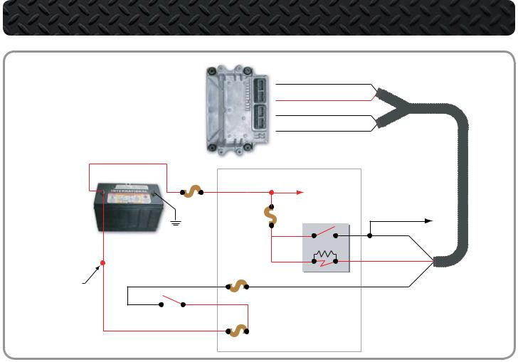
ECM Relay Circuit Operation
•The ECM controls its own power up and power down process. When the key is OFF, the ECM stays powered up for a brief period. The ECM then powers down after internal housekeeping functions have been completed.
Key Power
•The Run/Accessory position of the Key Switch receives battery voltage from the Power Distribution Center. When the key is ON, the switch supplies battery voltage through fuse F47 to ECM pin X3-3. Battery voltage is available at all times through fuse F38 to ECM relay pins 30 and 86.
•Pin 86 supplies voltage to the relay coil.
•Pin 85 connects the coil to pin X3-5 of the ECM.
•When the key is ON, voltage supplied to pin X3-3 signals the ECM that the operator is going to start the engine.
The ECM then supplies a ground circuit to pin X3-5. When this occurs, current flows through the ECM relay coil and creates a magnetic field causing the relay to latch. When latched, the relay connects pin 30 to pin 87 and supplies current to the ECM through pin X4-1 and X4-2.
Shut Down
•When the key is OFF and voltage is removed from ECM pin X3-3, the ECM shuts down the engine but keeps the ECM powered up briefly until the internal house keeping is completed.
22 |
International® VT 275 V6 Engine • Workhorse Chassis Applications • Revision 1.0 • © Copyright 2006 International Truck and Engine Corporation |

ELECTRONIC CONTROL SYSTEM
ECM Power Relay
DTC 112 Electrical system voltage B+ out-of-range high
The ECM detects an alternator output greater than 23 volts at ECM Pin X3-3 for more than 0.5 seconds.
Possible causes: • Voltage increases
•Jump starting the engine
•Incorrect external battery connections
DTC 113 Electrical system voltage B+ out-of-range low
The ECM detects less than 7 volts at ECM Pin X3-3 for more than 0.5 seconds.
Possible causes: • Discharged batteries
•Increased resistance in the battery feed circuits
•Failed alternator or ECM power relay
DTC 626 Unexpected reset fault
Set when power is interrupted to the ECM or causes an ECM power down.
Possible causes: • Loose or dirty connections at battery or ground cables
•Power feed wiring problems
•Low battery voltage
Voltage Checks - ECM Power Relay Socket
1.Turn Key Switch OFF.
2.Remove ECM relay and inspect for corroded terminals.
3.Connect relay breakout harness to relay and socket.
4.Measure voltage with Key Switch in the required test position.
TEST POINT |
KEY SWITCH |
SPECIFICATION |
COMMENTS |
|
|
|
|
85 to GND |
ON |
0.06 to 2 V |
• If greater than 2 volts, check for open or short to B+. |
|
|
|
|
85 to GND |
OFF |
B+ |
• If no voltage, check the fuse. |
|
for open |
|
• If fuse is good, check for open. |
|
|
|
|
86 to GND |
ON/OFF |
B+ |
• If no voltage, check the fuse. |
|
|
|
• If fuse is blown, check for short to ground. |
|
|
|
• If fuse is good, check for open. |
30 to GND |
ON |
B+ |
• If no voltage, check the fuse. |
|
|
|
• If fuse is blown, check for short to ground. |
|
|
|
• If fuse is good, check for open. |
|
|
|
|
87 to GND |
ON |
B+ |
• If no voltage, check for failed relay. |
|
|
|
|
87 to GND |
OFF |
O V |
• If greater than 0 volts, check for short to B+. |
|
|
|
|
If measurements are OK, send the vehicle to your International® dealer for further diagnostics.
International® VT 275 V6 Engine • Workhorse Chassis Applications • Revision 1.0 • © Copyright 2006 International Truck and Engine Corporation |
23 |
Loading...